Loading ...
Loading ...
Loading ...
e
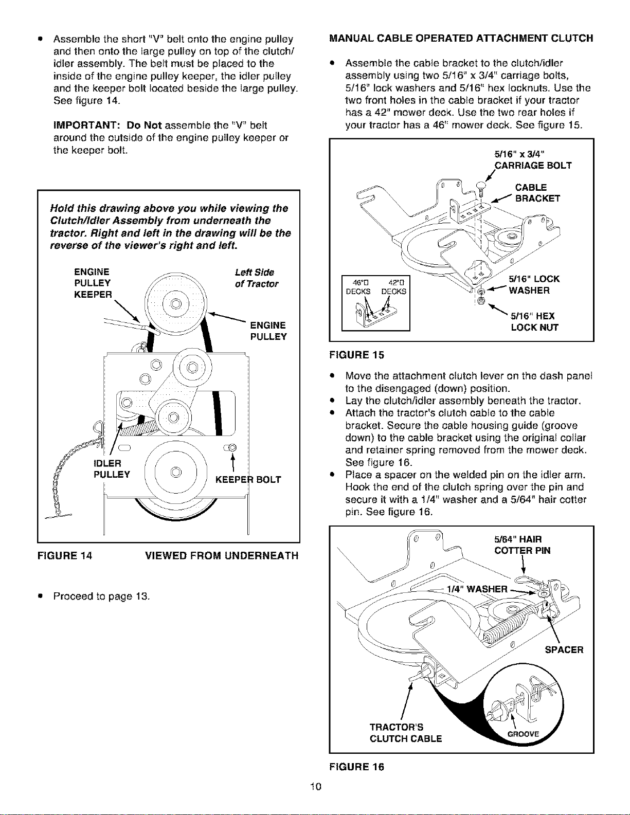
Assemble the short "V" belt onto the engine pulley
and then onto the large pulley on top of the clutch/
idler assembly. The belt must be placed to the
inside of the engine pulley keeper, the idler pulley
and the keeper bolt located beside the large pulley.
See figure 14.
IMPORTANT: Do Not assemble the "V" belt
around the outside of the engine pulley keeper or
the keeper bolt.
Hold this drawing above you while viewing the
Clutch/Idler Assembly from underneath the
tractor. Right and left in the drawing will be the
reverse of the viewer's right and left.
ENGINE Left Side
PULLEY of Tractor
KEEPER
ENGINE
PULLEY
IDLER
PULLEY
=tBOLT
FIGURE 14 VIEWED FROM UNDERNEATH
• Proceed to page 13.
MANUAL CABLE OPERATED ATTACHMENT CLUTCH
Assembte the cable bracket to the cIutchiidler
assembly using two 5/16" x 3/4" carriage boIts,
5/16" lock washers and 5/16" hex lecknuts. Use the
two front holes in the cabte bracket if your tractor
has a 42" mower deck. Use the two rear holes if
your tractor has a 46" mower deck. See figure 15.
_16"x 3/4"
CARRIAGE BOLT
CABLE
BRACKET
5/16" LOCK
WASHER
LOCKNUT
FIGURE 15
• Move the attachment clutch lever on the dash panel
to the disengaged (down) position.
• Lay the clutch/idler assembly beneath the tractor.
• Attach the tractor's clutch cable to the cable
bracket. Secure the cable housing guide (groove
down) to the cable bracket using the original collar
and retainer spring removed from the mower deck.
See figure 16.
• Place a spacer on the welded pin on the idler arm.
Hook the end of the clutch spring over the pin and
secure it with a 1/4" washer and a 5/64" hair cotter
pin. See figure 16.
5/64" HAIR
COTTER PIN
SPACER
!
TRACTOR'S
CLUTCH CABLE
FIGURE 16
lO
Loading ...
Loading ...
Loading ...