OWNER'S
MANUAL
MODEL NO.
917.299852
Caution:
Read and follow
all Safety Rules
and Instructions
Before Operating
This Eqmpment
£RRFTSMRN
5.0 HP
17INCH TINE WIDTH
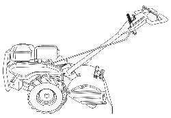
REAR TINE TILLER WITH
COUNTER ROTATING TINES
• Assembly
• Operation
• Customer Responsibilities
• Service and Adjustment
• Repair Parts
ii iii ii ill|m
Sears, Roebuck and Co., Hoffman Estates, IL. 60179 U.S.A.
i iii IIIIIHIr i iiiiiiiiii i h i ii i fflHrnlllln I1[I IIII
SAFETY RULES
Safe Operation Practices for Walk-Behind Powered Rotary Tillers
TRAINING
. Read the Owner's Manual carefully. Be thoroughly
familiar with the controls and the proper use of the
equipment. Know how to stop the unit and disengage
the controls quickly.
• Never allow children to operate the equipment. Never
allow adults to operate the equipment without proper
instruction.
• Keep the area ofoperation clear of all persons, particu-
:: lady small children, and pets.
PREPARATION
• Thoroughlyinspectthearea where theequipmentisto
be used and remove all foreignobjects.
• Disengage all clutches and shift into neutral before
starting the engine (motor).
• Do not operate the equipment without wearing ad-
equate outer garments. Wear footwear that will im-
prove footing on slippery surfaces.
• Handle fuel with care; it is highly flammable.
• Use an approved fuel container.
• Never add fuel to a running engine or hot engine.
• Fill fuel tank outdoors with extreme care. Never fill
fuel tank indoors.
° Replace gasoline cap securely and clean up spilled
fuel before restarting.
• Use extension cords and receptacles as specified by
the manufacturer for all units with electric drive motors
or electric starting motors.
• Never attempt to make any adjustments while the
engine (motor) is running (except where specifically
recommended by manufacturer).
OPERATION
, Do not put hands or feet near or under rotatingparts.
* Exercise extremecautionwhen operatingon orcross-
inggravel drives, walks, or roads.Stay alert for hidden
hazards or traffic.Do not carry passengers.
• After striking a foreign object,stop the engine (motor),
remove the wire from the spark plug, thoroughly in-
spect thetillerfor anydamage, and repairthe damage
before restartingand operatingthe tiller.
° Exercise cautionto avoid slipping or falling.
• If the unitshouldstart to vibrate abnormally,stop the
engine (motor) and check immediately for the cause.
Vibration is generally a warning of trouble.
• Stop the engine (motor) when leaving the operating
position.
• Take all possible precautions when leaving the ma-
chine unattended. Disengage the tines, shift into
neutral, and stop the engine.
= Before cleaning, repairing, or inspecting, shut off the
engineand make certain all moving partshavestopped.
Disconnect the spark plug wire, and keep the wire
away from the plug to prevent accidental starting.
Disconnect the cord on electric motors,
• Do not run the engine indoors; exhaust fumes are
dangerous.
° Never operate the tiller without proper guards, plates,
or other safety protective devices in place.
° Keep children and pets away.
• Do not overload the machine capacity byattempting to
tilt too deep at too fast a rate.
= Never operate the machine at high speeds on slippery
surfaces. Look behind and use care when backing.
• Never allow bystanders near the unit.
• Use only attachments and accessories approved by
the manufacturer of the tiller (such as wheel weights,
counterweights, cabs, and the like).
• Never operate the tiller without good visibility or light.
• Be careful when tilling in hard ground. The tines may
catch in the ground and propel the tiller forward. If this
occurs, letgo ofthe handlebars and do not restrain the
machine.
MAINTENANCE AND STORAGE
• Keep machine, attachments, and accessories insafe
wo_ing condition.
• Check shear pins, engine mounting bolts, and other
boltsat frequent intervals for propertightness to be
sure the equipment isin safe workingcondition.
• Never store themachine withfuel inthe fueltank inside
a building where ignition sources are present, such as
hot water and space heaters, clothesdryers, and the
like. Allow the engine to cool before storing in any
enclosure.
• Always refer to the operator's guide instructionsfor
important details if the tiller is to be stored for an
extended period.
: : -IMPORTANT- :
CAUTION, IMPORTANTS, AND NOTES ARE A MEANS OF ATTRACTING ATTENTION TO IMPORTANT OR CRITI-
CAL INFORMATION IN THIS MANUAL: ........
CAUTION: Look for this symbol to point
out important safety precautions. It
means--Attention! Become Alert! Your
.... safety is involved.
III
IMPORTANT: USED TO ALERT YOU THAT THERE IS A
POSSIBILITY OF DAMAGING THiS EQU[PMENT.
NOTE: Gives essential information that will aid you to better
understand, incorporate, or execute a particular set of instruc-
tions. ................................................
CONGRATULATIONS on your purchaseofa SearsTiller.
It has been designed, engineered and manufacturedto
giveyou the best possibledependabilityand performance.
Should you experience any problems you cannot easily
remedy, please contact your nearest authorized Sears
Service Center/Department. They have competent,well-
trained techniciansand the propertootstoserviceor repair
this unit. ....
Please read and retain this manual. The instructions will
enable you to assemble and maintain your tiller properly,
Always observe the "SAFETY RULES",
MODEL
NUMBER 917.299852
SERIAL
NUMBER
DATE OF
PURCHASE
THE MODEL AND SERIAL NUMBERS WILL BE
FOUND ON THE MODEL PLATE ATTACHED TO
THE TOP OF THE TRANSMISSION.
YOU SHOULD RECORD BOTH SERIAL NUMBER
AND DATE OF PURCHASE AND KEEP IN A SAFE
PLACE FOR FUTURE REFERENCE.
PRODUCT SPECIRCATIONS
HORSEPOWER,5.0,P
DISPLACEMENT: 12.57cu.in.
GASOLINECAPACITY: 3 Quarts :
UnleadedRegular
OIL: SAE 30W (Above32°F)
(CAPACITY:20oz.) SAE5W-30(Below32°F)
SPARKPLUG: Champion
(GAP: .030") RJ19LM
MAINTENANCE AGREEMENT
A SearsMaintenanceAgreement isavailable on thisprod-
uct. Contactyour nearest Sears store for details.
CUSTOMER RESPONSIBILITIES
• Read and observethe safety rules.
° Followaregularscheduleinmaintaining, caringfor and
usingyourtiller.
° Follow the instructions under the "Customer
Responsibilities"and "Storage" sections ofthisOwner's
Manual.
i i i II,H,H,,,HH,,,,III ,lUUlII III I I IIIII IIII
LIMITED TWO YEAR WARRANTY ON CRAFTSMAN TILLER
Fortwo yearsfrom date ofpurchase, when thisCraftsman Tillerismaintained,lubricated,and tuned up accordingto
the operating and maintenance instructions in the owner's manual, Sears will repair free of charge any defect in
materialor workmanship.
This Warranty does not cover:
• Expendableitemswhichbecome wornduring normal use,such as tines,spark plugs, air cleanersand belts.
• Repairs necessary because of operator abuse or negligence, includingbent crankshafts and the failure to
maintain the equipmentaccordingto the instructionscontainedinthe owner'smanual.
• If this Craftsman Tilleris usedfor commercialor rentalpurposes,this Warrantyapplies for only30 days from the
date of purchase.
WARRANTY SERVICE tS AVAILABLE BY RETURNING THE CRAFTSMAN TILLER TO THE NEAREST SEARS
SERVICE CENTER/DEPARTMENT IN THE UNITED STATES. THIS WARRANTY APPLIES ONLY WHILE THiS
PRODUCT IS IN USEIN THE UNITED STATES.
This Warranty givesyouspecific legalrights,and you may also haveotherrightswhichvaryfrom state to state.
SEARS, ROEBUCK AND CO., D/817 WA, HOFFMAN ESTATES, CHICAGO, ILLINOIS 60179
i
ilu ifll i i ill
- IMPORTANT-
This unitisequippedwithaninternalcombustionengine and shouldnotbe used onor near any unimprovedforest-covered,
brush-covered or grass covered land unlessthe engine's exhaust system is equipped with a spark arrester meeting
applicable localor state taws(ifany). ifa spark attester is used, itshouldbe maintained in effectiveworkingorder by the
operator. : i :
In the state ofCaliforniathe above isrequired bylaw (Section4442 ofthe CaliforniaPublicResources Code). Other states
may have similarlaws. Federal lawsapplyon federal lands. See yourSears AuthorizedService Center for sparkarrester.
Refer to the Repair Partssectionofthis manual for part number.
3
ill iiii ii iiii ii
LIiiiiiilll,ll,,l••;•• • ••• _ illii
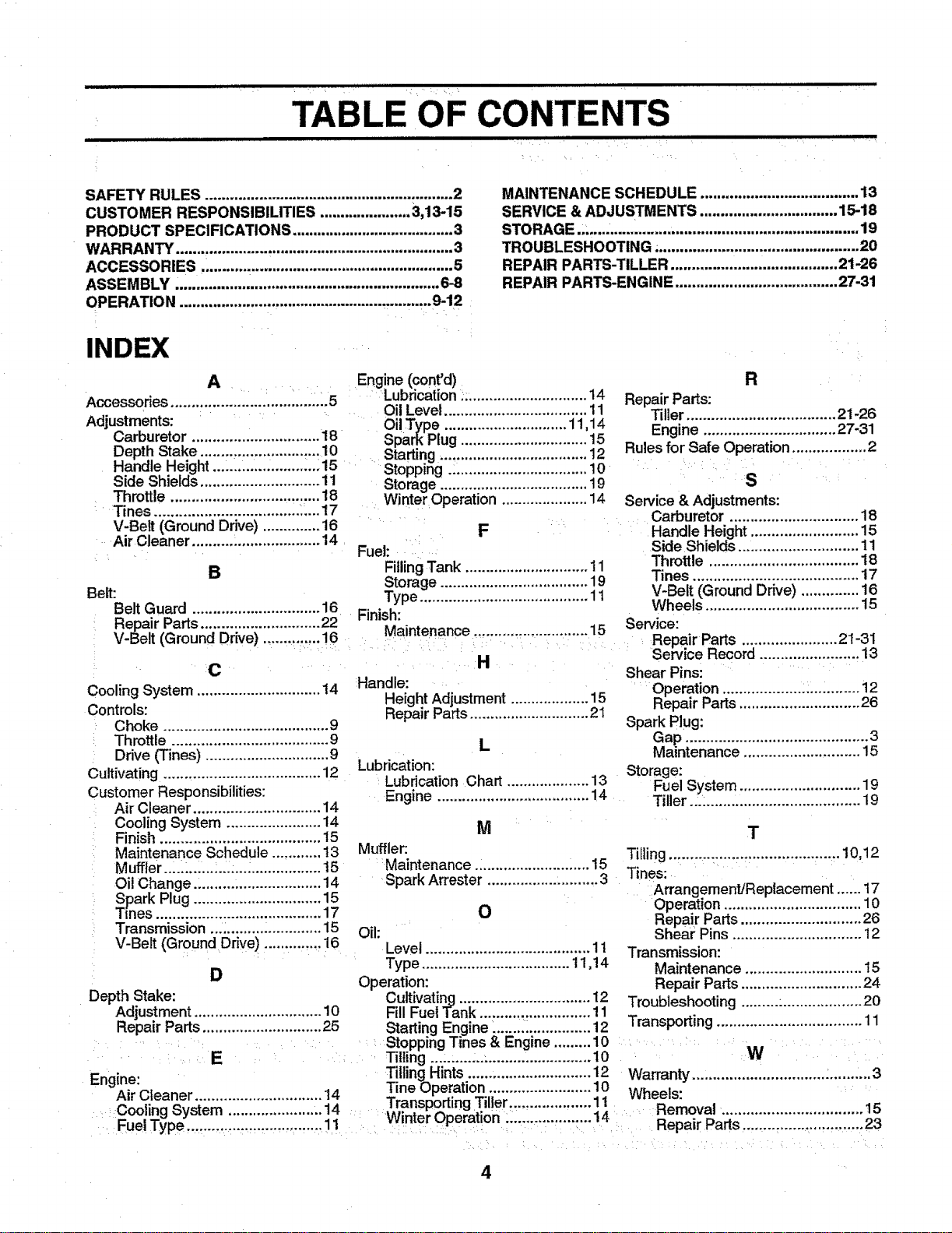
TABLE OF CONTENTS
ill iiilll iiiill,,i i iiiilll,llllll
SAFETY RULES ............................................................ 2
CUSTOMER RESPONSIBILITIES ...................... 3,13-15
PRODUCT SPECIFICATIONS ....................................... 3
WARRANT'/ ................................................................... 3
ACCESSORIES, ........................................................... 5
ASSEMBLY ................................................................ 6-8
OPERATION .......................................................... ..9-12
INDEX
MAINTENANCE SCHEDULE ...................................... 13
SERVICE & ADJUSTMENTS ................................. 15-18
STORAGE ..,................................................................. 19
TROUBLESHOOTING ;................................................ 20
REPAIR PARTS-TILLER ........................................ 21-26
REPAIR PARTS-ENGINE ....................................... 27-31
A Engine (cont'd)
.... _ Lubrication _.............................. 14
Accessories ....................... ............... 5
..... Oil Level ................................... 11
Adjustments: Oil Type .............................. 11 14
Carburetor ............................... 18 Spark Plug ............................... 15
Depth Stake .............................. 10 Starting. ................................... 12
Handle Height ...:.........: ........:..:15 .... Stopping .i................................ 10
Side Shields ............................. 11 Storage :................................... 19
Throttle .................................... 18 Winter Operation ..................... 14
:Tines ................................... _:_...17 .....
V-Belt (Ground Drive) .............. 16 .....
Air Cleaner .........._.................... 14 _ F
Fuel: .....
B FillingTank .............................. 11
Storage .................................... 19
Belt: Type ......................................... 11
R
Repair Parts:
Tiller .................................... 21-26
Engine ................................ 27-31
Rules for Safe Operation .................. 2
:S
Service & Adjustments:
Carburetor ............................... 18
Handle Height .......................... 15
Side Shields ............................. 11
Throttle .................................... 18
Tines ........................................ 17
V-Belt (Ground Drive) .............. 16
Wheels ..................................... 15
Belt Guard ............................... 16
Repair Parts ............................. 22
V-Be t (Ground Drive) ..............16
Cooling System .............................. 14
Controls:
Choke ........................................ 9
Throttle ...................................... 9
Drive (Tines) .............................. 9
Cultivating. ..................................... 12
Customer Responsibilities:
Air Cleaner ............................... 14
Cooling System ....................... 14
Finish ....................................... 15
Maintenance Schedule ............ t3
Muffler .,..L.,..:..I:..._ ................. 15
Oil Change ..........:.................... 14
Spark Plug ............................... 15
TEnes........................................ 17
Transmission...; ....................... 15
V-Belt (Ground Drive) .............. 16
D
Finish: ^ .
- _ervlce"
Ma ntenance ............................ 15 - .
:: _ : ..... Repair Parts ....................... 21-31
.......... _, ........ Sei_ice Record ........................ 13
n
Handle:
Height Adjustment.................. 115
Repair Parts ............................. 21
Shear Pins:
Operation .................... i............ 12
Repair Parts ............................. 26
Spark Plug:
L Gap ............................................ 3
Lubrication: Maintenance ............................ 15
Storage:
Lubrication Chart .................... 13 Fuel System ............................. 19
Engine .................................. 14 Tiller._: ..................................... 19
M T
Muffler:
Tilling ......................................... 10,12
Maintenance 15 Tines: i
Spark Arrester ........................... 3 Arrangement/Replacement ...... 17
Operation ................................. 10
Repair Parts ............................. 26
Shiraz:Pins ............................... 12
Transmission:
Maintenance ............................ 15
Repair Parts ............................. 24
O
Oil:
Level ........................................ 11
Type .................................... t1,14
Operation:
Depth Stake: Cultivatin_l ................................ 12 Troubleshooting .........:................... 20
Adjustment ............................... 10 Fill Fuel "l_'ank........................... 11
Repair Parts ............................. 25 Starting Engine _....................... 12 Transporting ................................... 11
: : _:_Stopping Tines & Engine ......... 10
• : E _ ..... Tilling ...:.,...:..: ......................... 10 i :: .... i: W :
En;'ine" Tilling Hints .............................. 12 Warranty ............ ""i ............... :....""..3
_-" "-' 14 Tine Operation ............. 10
AsrL;teaner................................. "........... 1 Wheels: :
Coolinn System 14 Transporting T,Iler.................... 1
" ....................... 11 : Winter Operation .... 14 Removal. ................................. 15
FueIType ............,.,,... .......... ........ : i :ii: ..... : T"!'=,'",":"" ..... Repair Parts............................. 23
: i
4
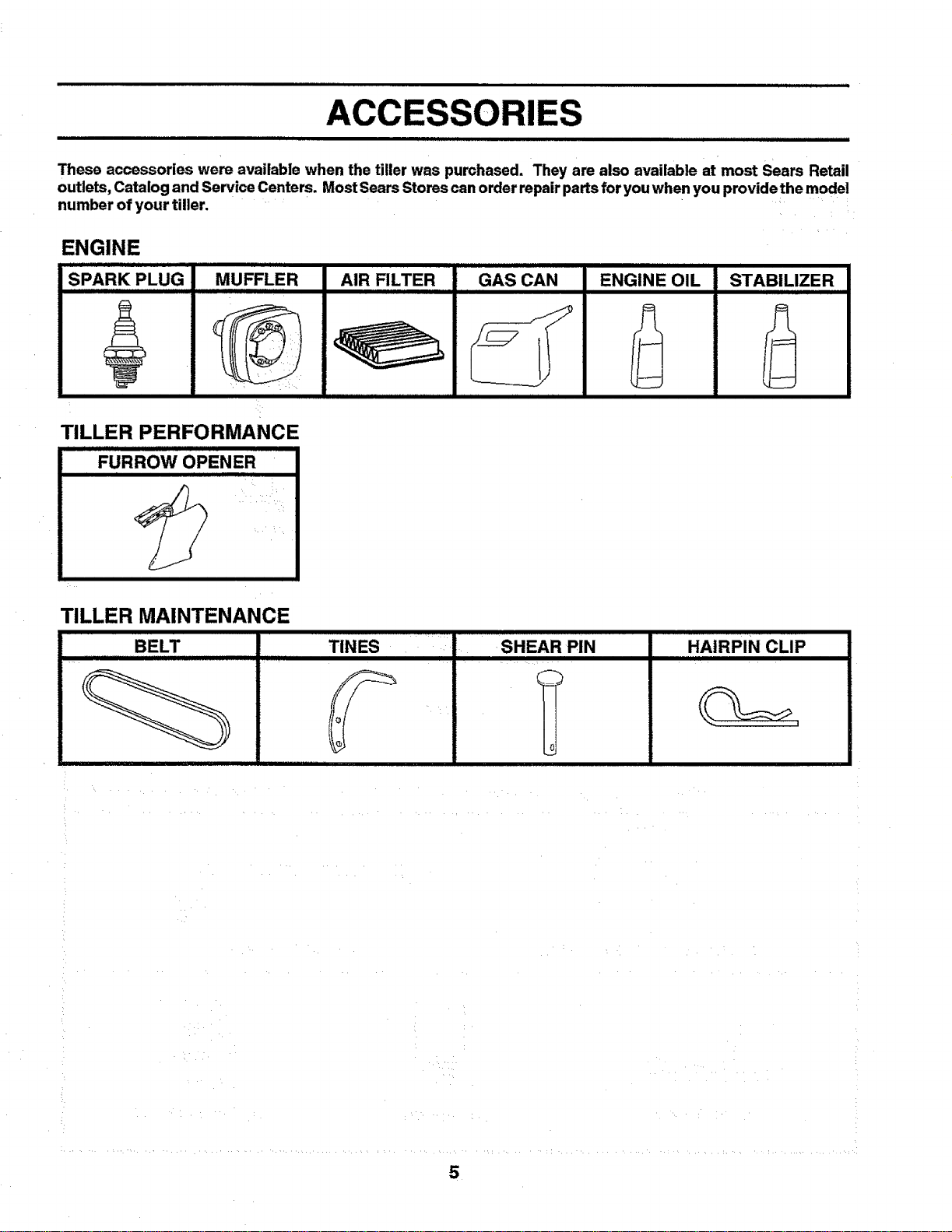
A RIES
These accessories were available when the tiller was purchased. They are also available at most Sears Retail
outlets, Catalog and Service Centers. Most Sears Stores can order repair parts for you when you providethe model
number of your tiller.
ENGINE
SPARK PLUG MUFFLER AIR FILTER
IIIIII I
GAS CAN
ii iii
ENGINE OIL
TILLER PERFORMANCE
FURROW OPENER
STABILIZER
TILLER MAINTENANCE
BELT
TINES iSHEAR PIN
_c
HAIRPIN CLIP
IIIIIII II IIIII
5
ASSEMBLY
(1) Utility knife
(1) Wire cutter
(1) Screwdriver
(1) Tire pressure gauge
(1) Pair of pliers
(1) 9/16" wrench (or 9/16" socket, ratchet, and exten-
sion;or adjustable wrench)
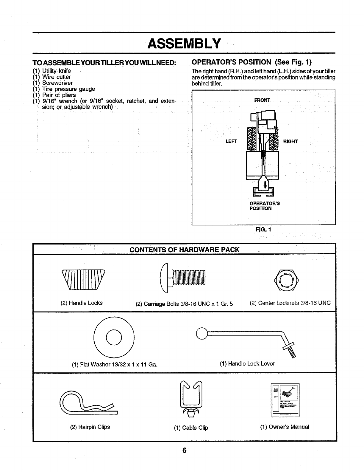
OPERATOR'S POSITION (See Fig, 1)
The righthand(R.H.) and left hand(L.H.) sides ofyourtiller
are determinedfromthe operator'spositionwhilestanding
behind tiller.
LEFT
FRONT
RIGHT
OPERATOR'S
POSITION
FIG. 1
i i rIIIIII
CONTENTS OF HARDWARE PACK
/IIIHIIIY
(2) Handle Locks
(2) Carriage Bolts 3/8-16 UNC x I Gr. 5 (2) Center Locknuts 3/8-16 UNC
(1) Fiat Washer 13/32 x 1 x 11 Ga.
i
©
U
(1) Cable Clip
(1) Handle Lock Lever
(2) HairpinClips (1) Owners Manual
IIII IL II illl I I I I IIIII II I IIIIII
6:
ASSEMBLY
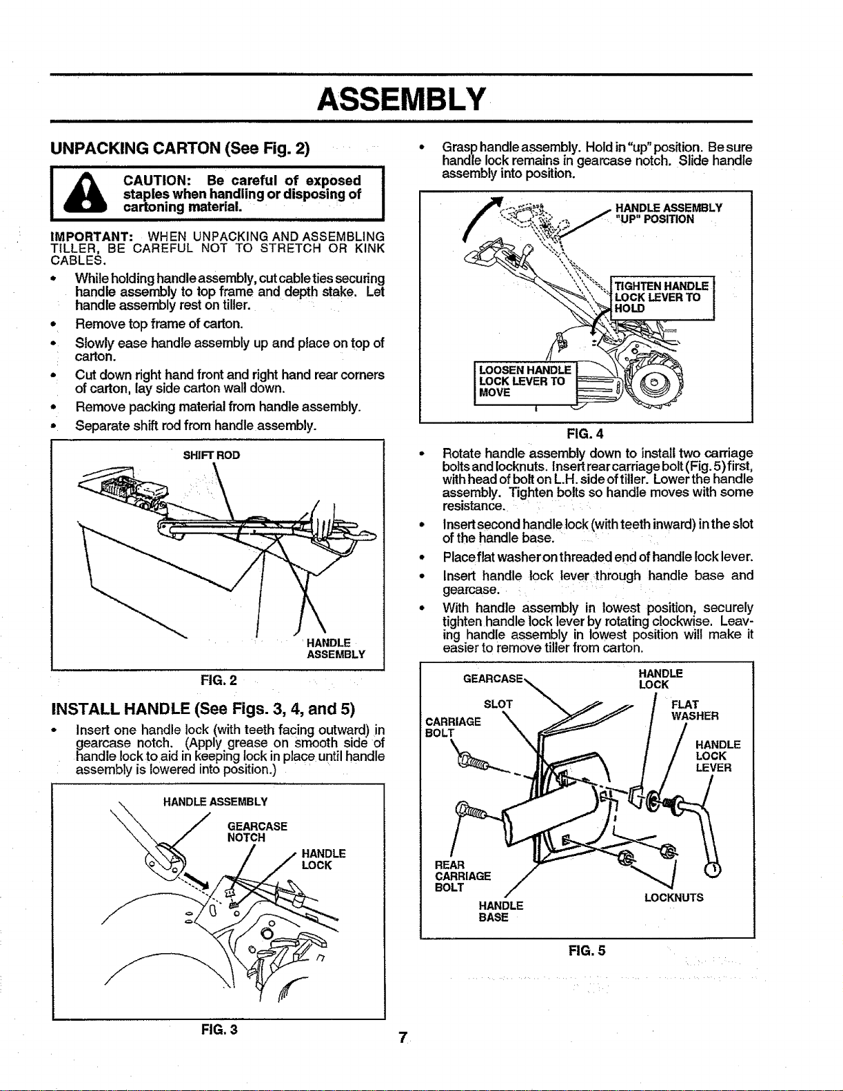
UNPACKING CARTON (See Fig. 2)
I_ CAUTION: Be careful of exposed
I
staples when handling or disposing of I
cartoning material.
IMPORTANT: WHEN UNPACKING AND ASSEMBLING
TILLER, BE CAREFUL NOT TO STRETCH OR KINK
CABLES.
* While holding handle assembly, cut cableties securing
handle assembly to top frame and depth stake. Let
handle assembly rest on tiller.
Remove top frame of carton.
Slowly ease handle assembly up and place on top of
carton.
Cut down right handfront and righthand rear corners
of carton, lay side carton wall down.
Remove packing material from handle assembly.
Separate shift rod from handle assembly.
SHIFT ROD
.... HANDLE
ASSEMBLY
FIG. 2
INSTALL HANDLE (See Figs. 3, 4, and 5)
- Insert one handle lock (with teeth facing outward)in
gearcase notch. (Apply grease on smooth side of
handle lock toaid in keeping lock in place untilhandle
assembly is lowered into position.)
HANDLE ASSEMBLY
Grasp handle assembly. Holdin "up" position. Be sure
handle lockremains in geamase notch. Slide handle
assembly into position.
HANDLE ASSEMBLY
"UP" POSITION
TIGHTEN HANDLE
LOCKLEVERTO
iHOLO
FIG. 4
• Rotate handle assembly down to install two carriage
boltsand Iocknuts,Insert rear carriage bolt(Fig.5) first,
withhead ofbolton L.H.sideoftiller. Lowerthe handle
assembly. Tighten bolts so handle moves with some
resistance.
• Insertsecond handle]ock (with teethinward) in the slot
of the handle base.
° Placeflat washeron threaded end of handle Iocklever.
• Insert handle lock lever through handle base and
gearcase.
° With handle assembly in lowest position, securely
tighten handle lock lever by rotating clockwise. Leav-
ing handle assembly in lowest position will make it
easier to remove tiller from carton.
HANDLE
LOCK
SLOT FLAT
CARRIAGE WASHER
:BOLT
HANDLE
LOCK
LEVER
REAR
CARRIAGE
BOLT
HANDLE
BASE
LOCKNUTS
FIG. 5
FIG, 3 7
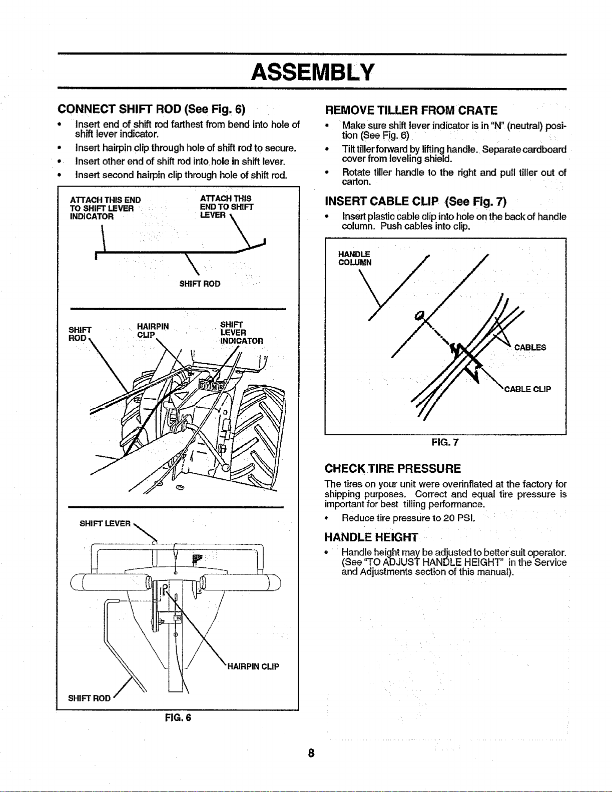
CONNECT SHIFT ROD (See Fig. 6)
. Insert end of shift rodfarthest from bend intohole of
shift lever indicator,
• Insert hairpinclip through hole of shift rodto secure.
° insert otherend of shift rod into hole in shift lever.
° Insert second hairpinclipthroughholeof shift rod.
ATTACHTHISEND
TO SHIFT LEVER :
INDICATOR
I
ATTACH THIS
END TO SHIFT
LEVER .\_,_
SHIFT ROD
illliH ii j ii ii llll i ii ...............
SHIFT : _ HAIRPIN SHIFT
CLIP _ LEVER
INDICATOR
SHIFT LEVER
HAIRPINCLIP
SHIFT ROD
FIG. 6
REMOVE TILLER FROM CRATE
g
Make sure shift lever indicator isin "N" (neutral) posi-
tion (See Fig. 6)
Tilt tiller forward by lifting handle. Separate cardboard
cover from leveling shield.
Rotate tiller handle to the right and pull tiller out of
carton.
INSERT CABLE CLIP (See Fig. 7)
• Insert plastic cable clip intohole on the back of handle
column. Pushcables intoclip.
CABLECLIP
FIG. 7
CHECK TIRE PRESSURE
The tires on your unit were overinflated at the factory for
shipping purposes. Correct and equal tire pressure is
important for best tilling performance.
• Reduce tire pressure to 20 PSI.
HANDLE HEIGHT
• Hand!e height may be adjusted to better suit operator.
(See q'O ADJUST HANDLE HEIGHT' inthe Service
and Adjustments section of this manual).
8
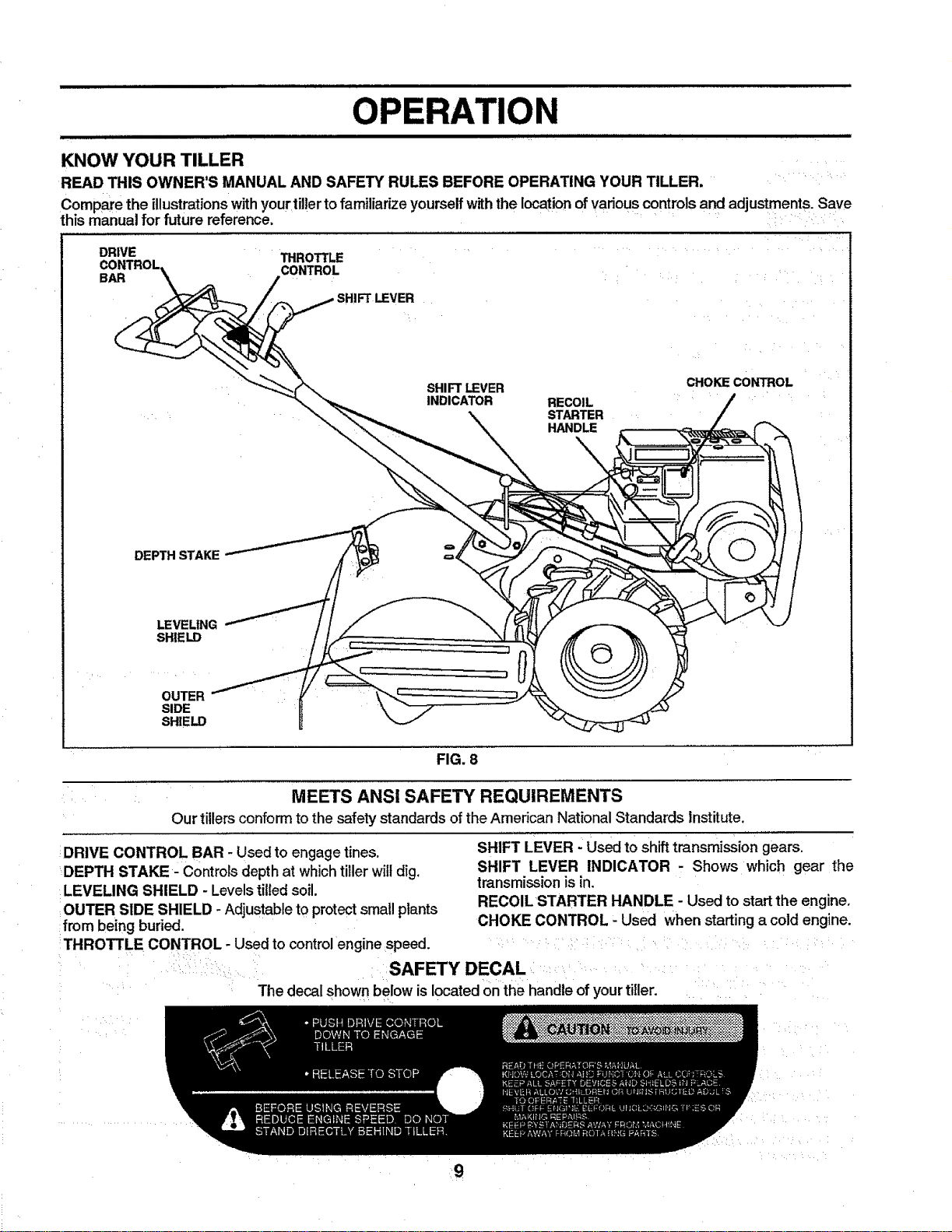
KNOW YOUR TILLER
READ THIS OWNER'S MANUAL AND SAFETY RULES BEFORE OPERATING YOUR TILLER.
Compare the illustrationswithyour til!ertofamiliarize yourselfwiththe location ofvarious controlsand adjustments.Save
this manual for future reference. ......
DRIVE THROTTLE
CONTROL
BAR
r LEVER
SHIFT LEVER
INDICATOR
RECOIL
STARTER
HANDLE
CHOKE CONTROL
DEPTH STAKE
LEVELING
SHIELD
OUTER
SIDE
SHIELD
FIG. 8
MEETS ANSI SAFETY REQUIREMENTS
Our tillers conform to the safety standards of the American National Standards Institute.
DRIVE CONTROL BAR - Used to engage tines.
DEPTH STAKE- Controls depthat whichtillerwilldig.
LEVELING SHIELD - Levelstilled soil.
OUTER SIDE SHIELD - Adjustable tOprotectsmall plants
from being buried.
THROTTLE CONTROL - Used to controlengine speed.
SHIFT LEVER - Used to shift transmission gears.
SHIFT LEVER INDICATOR - Shows which gear the
transmission is in.
RECOIL STARTER HANDLE - Used to start the engine.
CHOKE CONTROL - Used when starting a cold engine.
SAFETY DECAL
The decal shown below is located on the handle ofyour tiller.
q I qlm Ill IIIIIJl I J IIIlllJ/JJ_lJ/gll/;ll JJJII II/IIqlIIIIHJHIH I I II III IIIIIIIIIII III II II
OPERATION
The operation of any tiller can result in foreign objects thrown into the eyes, which can
result in severe eye damage. Always wear safety glasses or eye shields before starting
your tiller and while tilling. We recommend wide vision safety mask for over the spec-
tacles or standard safety glasses.
HOW TO USE YOUR TILLER
Know how to operate all controlsbefore adding fuel and
oil or attemptingto start engine.
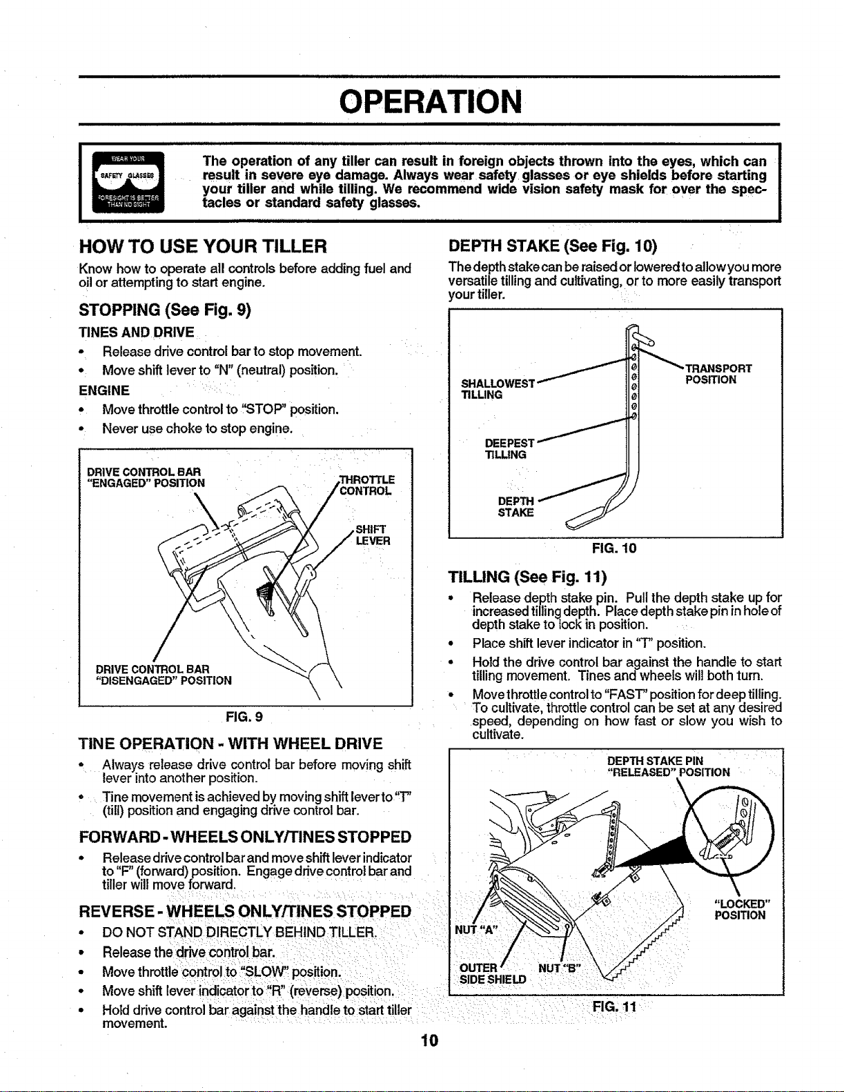
STOPPING (See Fig. 9)
TINES AND DRIVE
• Release drive controlbar to stop movement.
• Move shiftlever to "N" (neutral) position.
ENGINE _ :
• Move throttlecontrolto "STOP" position.
• Never use choke to stop engine.
DRIVE CONTROL BAR
"ENGAGED" POSITION
,SHIFT
LEVER
FIG. 9
DRIVECONTROLBAR
"DISENGAGED" POSITION
TINE OPERATION - WITH WHEEL DRIVE
* Always release drive control bar before moving shift
lever intoanother position.
• Tine movement is achieved by moving shift leverto"T"
(till) position and engaging drive controlbar.
FORWARD-WHEELS ONLY/TINES STOPPED
• Release drivecontrol bar and move shift lever indicator
to"F" (forward) position. Engage drive control bar and
tiller will move forward.
REVERSE- WHEELS ONLY/TINES STOPPED
• DO NOT STAND DIRECTLY BEHIND TILLER.
• Release thedrive controlbar.
• Move throttlecontrolto "SLOW' position.
• Move shift lever indicatorto:,R" (reverse) position.
• Hold drivecontrolbar against the handle to starttiller
movement.
i iiiii iiiiiiiiiii iii
DEPTH STAKE (See Fig. 10)
The depthstakecanbe raisedorloweredtoallowyou more
versatiletillingand cultivating,or to more easily transport
,ourtiller.
SHALLOWES1
TILLING
TILLING
POSITION
FIG. 10
TILLING (See Fig. 11)
• Release depth stake pin. Pull the depth stake up for
increased tilling depth. Place depth stake pin in hole of
depth stake to lock in position.
• Place shift lever indicator in '3" position.
• Hold the drive control bar against the handle to start
tilling movement. Tines and wheels wil! both turn.
• Move throtttecontrol to "FAST" position for deep tilling.
To cultivate, throttle control can be set at any desired
speed, depending on how fast or slow you wish to
cultivate.
DEPTHSTAKEPIN
"RELEASED"POSITION
\
NUT "A"
"LOCKED"
POSITION
NUT"B"
SIDE SHIELD
FIG, 11
10
TURNING
Release the ddve control bar.
Move throttlecontrol to "SLOW" position.
Place shift lever indicator in "F, (forward)position.
Tines will not turn.
Lift handle to raise tines out of ground.
Swingthe handle inthe opposite directionyou wish to
turn, being careful to keep feet and legs away from
tines. ..... ....
When you have completed your turn-around, release
thedr'P#econtrol barand Iowerhandle. Ptaceshift lever
in 'T' (till) position and move throttle control to desired
speed. To begin tilling, hold drive control bar against
the handle.
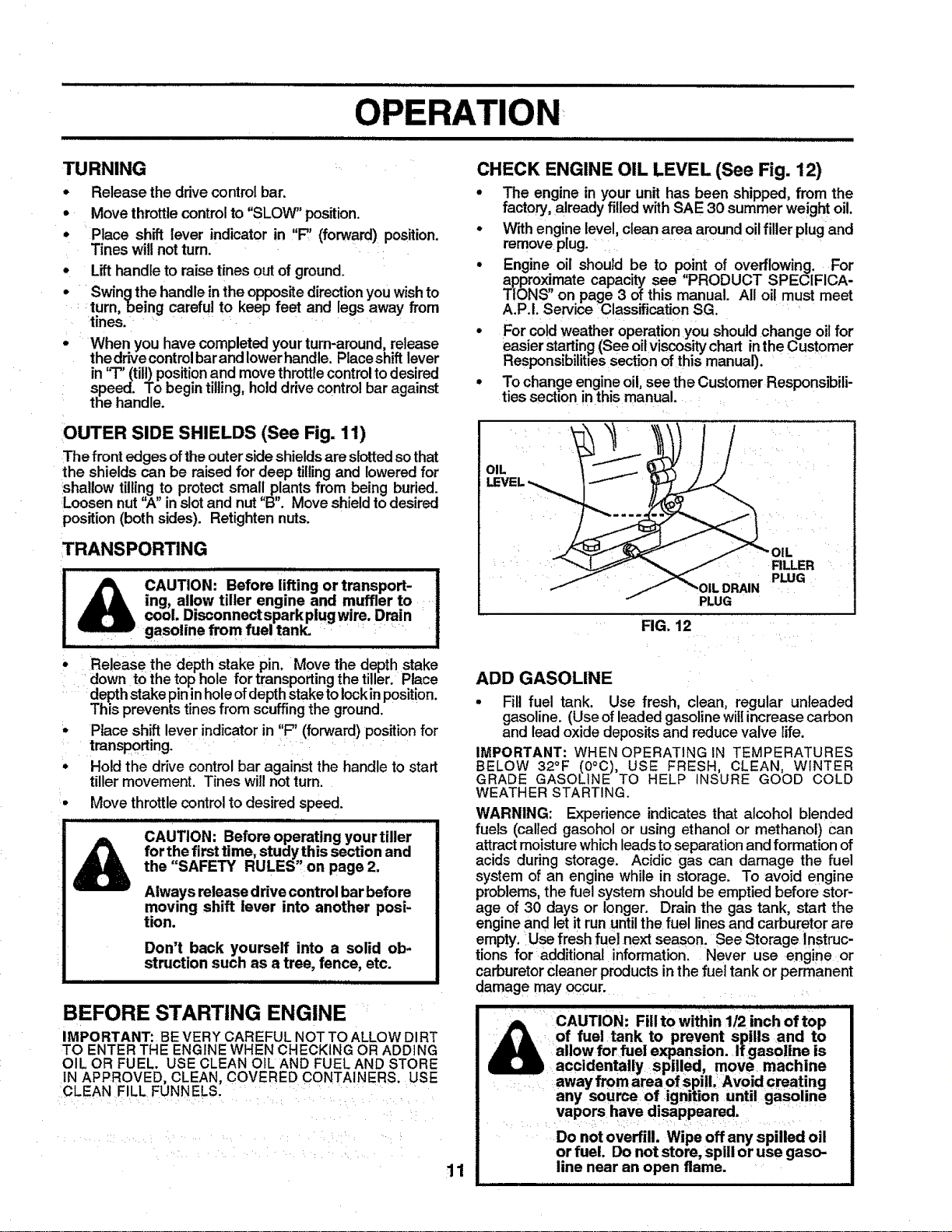
OUTER SIDE SHIELDS (See Fig. 11)
The front edges of the outer side shields are slotted so that
the shields can be raised for deep tilling and lowered for
:shallow tilling to protect small plants from being buried.
Loosen nut "A" in slot and nut "B". Move shield to desired
position (both sides). Retighten nuts.
TRANSPORTING
& cAUT;0.: 0.tro...o.-!
ing, allow tiller engine and muffler to !
cool. Disconnectsparkplugwire. Drain !
gasoline from fuel tank. : !
• Releasethe depth stake pin. Move the depth stake
down to the top hole for transporting the tiller. Place
depth stake pin in hole ofdepth stake to lock in position.
This prevents tines from scuffing the ground.
, Place shift lever indicator in "F" (forward) position for
transporting. ....
• Hold the drive control bar against the handle to start
tiller movement. Tines will not turn.
• Move throttlecontrol to desired speed.
CAUTION: Before operating your tiller
for the first time, studythis section and
the "SAFETY RULES',on page 2.
Always release drive control bar before
moving shift lever into another posi-
tion.
Don't back yourself into a solid ob*
struction such as a tree, fence, etc.
BEFORE STARTING ENGINE
IMPORTANT: BEVERY CAREFUL NOT TO ALLOW DIRT
TO ENTER THE ENGINEWHEN CHECKING OR ADDING
OIL OR FUEL. USE CLEAN OIL AND FUEL AND STORE
IN APPROVED, CLEAN, COVERED CONTA NERS. USE
CLEAN FILL FUNNELS. .... :
CHECK ENGINE OIL LEVEL (See Fig. 12)
• The engine in your unit has been shipped, from the
factory, already filledwith SAE 30 summer weight oil.
• With engine level, clean area aroundoilfillerplug and
remove plug. .......
° Engine oil should be to point of overflowing. For
approximate capacity see "PRODUCT SPECIFICA-
TIONS" on page 3 of this manual. All oil must meet
A.P.I. Service Classification SG.
° For co!d weather operation you should change oil for
easier startin_ (See oil viscositychart in the Customer
Responsibilities section of this manual).
° To change engine oil,see the Customer Responsibili-
ties section inthis manual.
OIL
PLUG
FIG. 12
FILLER
PLUG
11
ADD GASOLINE
• Fill fuel tank. Use fresh, clean, regular unleaded
gasoline. (Use of leaded gasoline will increase carbon
and lead oxide deposits and reduce valve life.
IMPORTANT: WHEN OPERATING IN TEMPERATURES
BELOW 32°F (O°C), USE FRESH, CLEAN, WINTER
GRADE GASOLINE TO HELP INSURE GOOD COLD
WEATHER STARTING.
WARNING: Experience indicates that alcohol blended
fuels (called gasohol or using ethanol or methanol) can
attract moisture which leads to separation and formation of
acids during storage. Acidic gas can damage the fuel
system of an engine while in storage. To avoid engine
problems,the fuel system should be emptied before stor-
age of 30 days or longer. Drain the gas tank, start the
engine and let it run until the fuel lines and carburetor are
empty. Use fresh fuel next season. See Storage Instruc-
tions for additional information. Never use engine or
carburetor cleaner products in the fuel tank or permanent
damage may occur.
CAUTION: Fill to within 1/2 inch of top
JIlL of fuel tank to prevent spills and to
allow for fuel expansion. Ifgasoline is
U accidentally spilled, move machine
away from area of spill: Avoid creating
any source of ignition until gasoline
vapors have disappeared.
Do not overfill. Wipe off any spilled oil
or fuel. Do not store, spill or use gaso-
line near an open flame.
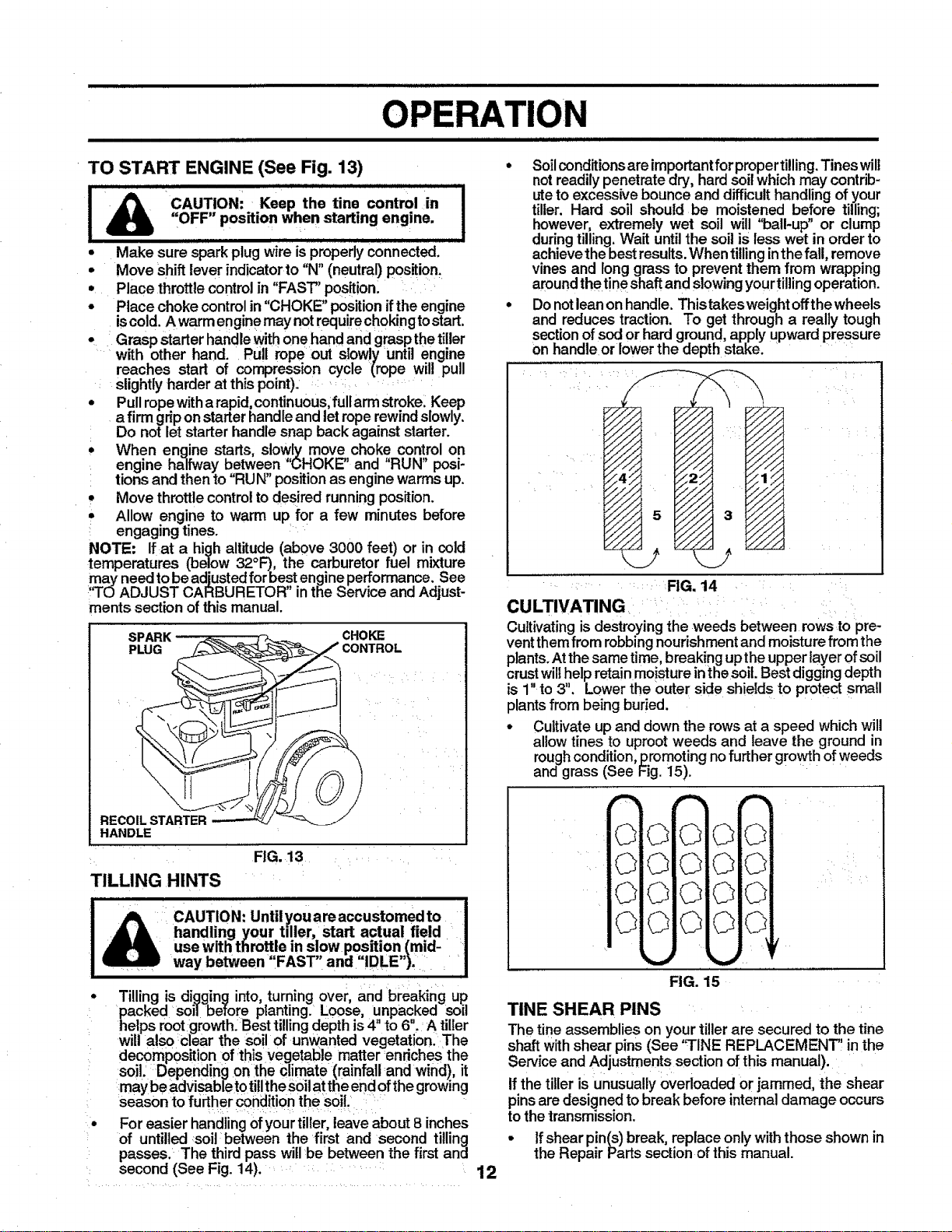
TO START ENGINE (See Fig. 13)
CAUTION= Keep the tine control in !
411
"OFF" position when starting engine. !
• Make sure spark plug wire isproperly connected.
- Move shift lever indicatorto "N" (neutral) position_
• Place throttle control in "FAST" position:
• Place choke controlin "CHOKE" position if the engine
iscold. A warm engine may not require choking tostart.
, Grasp starter handle withone hand and graspthe tiller
.....with other hand. Pull rope out slowly until engine
reaches start of compression cycle (rope will pull
: slightly harder at this point). :: ': .....
• Pull rope with a rapid, continuous, fullarm stroke: Keep
a firm grip on starter handle and let rope rewind slowly.
Do not let starter handle snap back against starter.
• When engine starts, slowi_ move,choke con!rol on
engine halfway between CHOKE' and RUN posi-
tions and then to "RUN" position as engine warms up.
• Move throttle control to desired running position.
• Allow engine to warm up for a few minutes before
engaging tines.
_IOTE: Ifat a high altitude (above 3000 feet) or in cold
temperatures (below 32°F), the carburetor fuel mixture
may need to beadjusted for best engine performance. See
:"TOADJUST CARBURETOR" in the Service and Adjust-
ments section of this manual.
SPARK - :_. _ CHOKE
PLUG __ CONTROL
O
REC -------'-
HANDLE
FIG. 13
TILLING HINTS
CAUTION: Until you areaccustomed to
handling your tiller, start actual field
usewiththro eins!owpositto_.,pid-
way between FAST and IDLE
Tilling is digging into, turning over, and breaking up
packed soil before planting. Loose, unpacked soil
helps rootgrowth.Besttillingdepth is4 to 6. A tiller
will also clear the soil of unwanted vegetation. The
decomposition of thisvegetable matter :enrichesthe
soil. Depending on :theclimate (rainfall:andwind), it
may be aldvisableto tilltheSoilat theendofthegrowing
season tofurther condition thesoil.
Foreasier handlingofyourtiller,leave about8 inches
of untilled soil between the first and second tilling
passes. The third pass willbe between the first and
second (See Fig. 14).
iii iiiii iiiii
o
12
Soilconditions are importantfor propertilling. Tines will
not readily penetrate dry, hard soil which may contrib-
uteto excessive bounce and difficult handling of your
tiller. Hard soil should be moistened before tilling;
however, extremely wet soil will "ball-up" or clump
during tilling. Wait until the soil is less wet in order to
achieve the best results. When tillinginthe fall, remove
vines and long grass to prevent them from wrapping
around the tine shaft and slowing your tillingoperation.
Donot lean on handle. This takes ,weightoff the wheels
and reduces traction. To get through a really tough
section of sod or hard ground, apply upward pressure
on handle or lower the depth stake. .....
........ FIG. 14 : ::
CULTIVATING ....:: i
Cultivating is destroying the weeds between rows to pre-
vent them from robbing nourishment and moisture from the
plants. At the same time, breaking upthe upper layer ofsoil
crust wi thelp retain moisture in the soil. Best digging depth
is 1" to 3". Lower the outer side shields to protectsmall
plants from being buried.
• Cultivate up and down the rows at a speed which will
allow tines to uproot weeds and leave the ground in
rough condition,promoting no further growth of weeds
and grass (See Fig. 15). ....
f-,_j
L.._l
_.r_l
FIG. 15
TINE SHEAR PINS
The tine assemblies on yourtiller are secured to the tine
shaftwithshear pins (See 'q-INE REPLACEMENT, in the
Service and Adjustmentssectionofthis manual).
If the tiller isunusually ovedoaded or jammed, the shear
pinsare designed tobreak before internaldamage occurs
tothe transmission.
• If shear pin(s) break, replace onlywiththose shown in
the Repair Partssection ofthis manual.
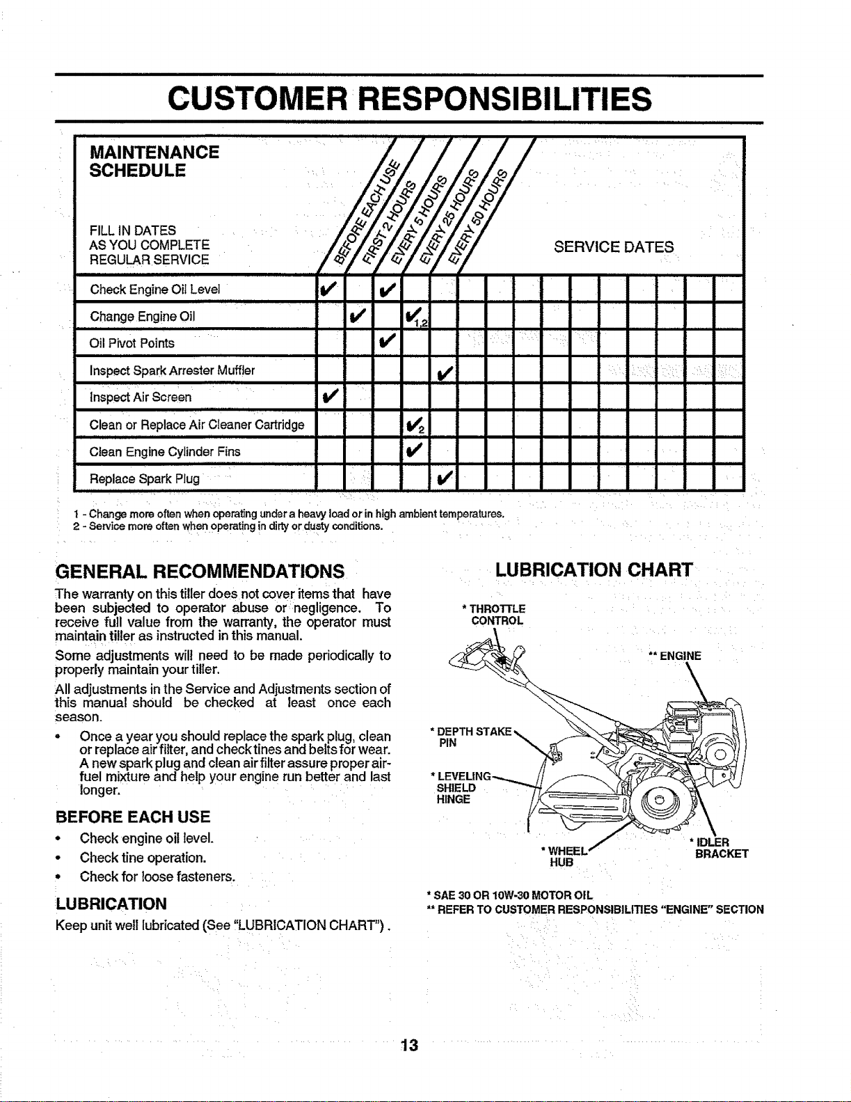
...........................RES PoNSI BILITI ES.......
J_H_II2_UUlIIIIIIIIIIIIIIIIIIIIIIIIIIIIIIIIIII II I III III I I ................................
MAINTENANCE __
SCHEDULE
FILLINDATES _ /__-q_/._,
YOOLEREGULAR SERVICE t_?
Check Engine Oil Level 1_ I_
Change Engine Oil _ " If K2
Oil Pivot Points ......
SERVICE
nnllllllilll i IL I I
•i
,,,,,,,,,,.,,, ,,,,,,. ,,,, ,,,,.,,,, ,,,,,
i:: I : i¸¸ii•
nspectSparkArrester Muffler .!_
Inspect Air Screen
Clean Engine Cylinder Fins b4' -
q
Replace Spark Plug .... t_
t - Change more often when operating undera heavy load or in highambient temperatures. _
2 - Service more often whet10Perat!ng in difiy or dustyconditions. ..........
GENERAL RECOMMENDATIONS
The warrantyon this tillerdoes not cover itemsthat have
been subjected to operator abuse or negligence. To
receive full value from the warranty, the operator must
maintain tiller as instructed in this manual.
Some adjustments wilt need to be made periodically to
properly maintain your tiller.
All adjustments in the Service and Adjustments section of
this manual should be checked at least once each
season.
Once a year you should replace the spark plug, clean
or replace air filter, and check tines and belts for wear.
A new spark plug and clean air filter assure proper air-
fuel mixture and help your engine run better and last
longer.
BEFORE EACH USE
• Check engine oil level.
• Check tine operation.
• Check for loose fasteners.
LUBRICATION
Keep unit well lubricated (See "LUBRICATION CHART").
LUBRICATION CHART
* THROTI'LE
CONTROL
* DEPTH STAKE _. _--__\_--&_) ..._-_
.PIN "_ :_
LEVEL|NG_ // _ _'L/Y__ !
SHIELD _"'.__ ,,,_._. _%J k.j
...... _ _ .pcE__
* WHEEL" BRACKET
HUB
* 8AE 30 OR 10W-30 MOTOR OIL
** REFER TO CUSTOMER RESPONSIBILITIES "ENGINE" SECTION
13
i ii
CU
iiiiij/llll ii 1/11iiiii iiiiii i i
Disconnect spark plugwire beforeperformingany maintenance (exceptcarburetor adjustment)to prevent I
accidental startingofengine.
!
Preventfires! Keeptheenginefreeofgrass,leaves,spilledoil, orfuel. Removefuelfrom tankbeforetipping
unitfor maintenance. Cleanmufflerareaof altgrass,dirt, anddebris.
Do nottouch hot muffleror cylinderfinsas contact maycauseburns.
ENGINE
LUBRICATION
Use only: high quality detergent oil rated withAPI service
c assific;_tion SG. Select the oil's SAE viscosity grade
according to your expected temperature.
i
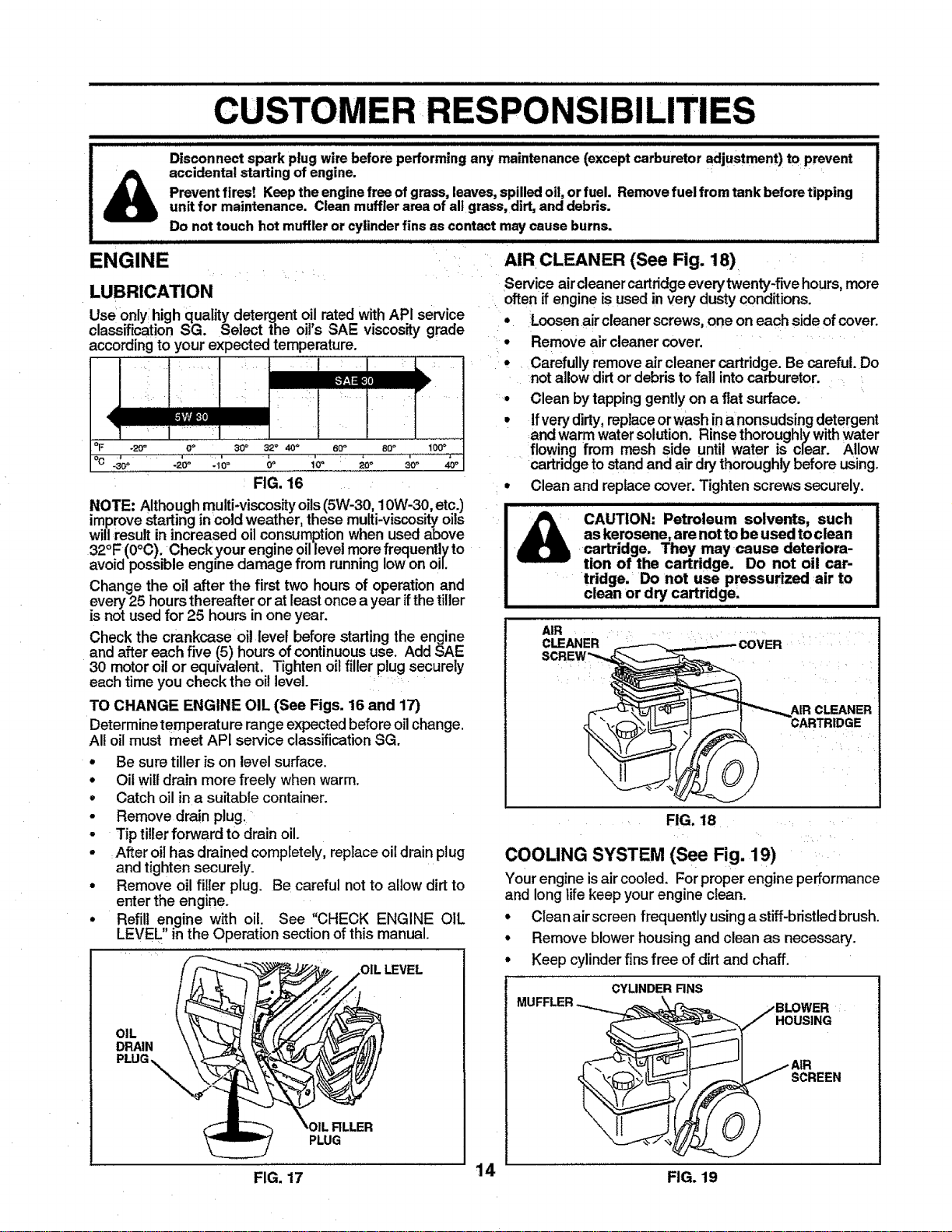
oF .20_ 0 o 30 ° 32 ° 40+ 60_ 80 + t00 °
°o ' ' ........'...... _ 1'0 _ _oo " ................'-
-30° -2Ce +10° ° . 30 + 40_
FIG. 16
NOTE: Although multi-viscosity oils (5W-30, 10W-30, etc.)
improve starting incold weather, these multi-viscosity oils
will result in increased oil consumption when used above
32°F (0°C). Checkyour engine oil level more frequently to
avoid possible engine damage from running low on oiL
Change the oil after the first two hours of operation and
every 25 hours thereafter or at least once a year ifthe tiller
is not used for 25 hours inone year.
Check the crankcase oil level before starting the engine
and after each five (5) hours of continuous use. Add SAE
30 motor oil or equivalent. Tighten oil filler plug securely
each time you check the oil level.
TO CHANGE ENGINE OIL (See Figs. 16 and 17)
Determinetemperature range expected before oil change.
All oil must meet API service classification SG.
• Be sure tiller is on level surface.
• Oil will drain more freely when warm.
• Catch oil in a suitable container.
• Remove drain plug.
• Tip tiller forward to drain oil.
• After oil has drained completely, replace oil drain plug
and tighten securely.
• Remove oil filler plug. Be careful not to allow dirt to
enter the engine.
• Refill engine with oil. See "CHECK ENGINE OIL
LEVEL" in the Operation section of this manual.
OIL
DRAIN
PLUG
FILLER
PLUG
FIG. 17
AIR CLEANER (See Fig. 18)
Service aircleaner cartridge every twenty-five hours, more
often _fengine isused in very dusty conditions.
* Loosen aircleaner screws, one on each side of cover.
o Remove air cleaner cover. ....
o Carefully remove air cleaner cartridge. Be careful. Do
not allow dirt or debris to fall into carburetor.
° Clean by tapping gently on a flat surface.
. Ifvery dirty, replace or wash in anonsudsing detergent
and warm water solution. Rinse thoroughly with Water
flowing from mesh side until water is clear. Allow
cartridge to stand and air dry thoroughly before using.
. Clean and replace cover. Tighten screws securely.
! & CAUTION: Petroleum solvents, such
as kerosene, are not to be used toclean
cartridge. They may cause deteriora-
tion of the cartridge. Do not oil car-
tridge. Do not use pressurized air to
clean or dry cartridge.
AIR
CLEANER
SCREW"_
COVER
;]lJ _AIR CLEANER
FIG. 18
14
COOLING SYSTEM (See Fig. 19)
Your engine isair cooled. For proper engine performance
and long life keep your engine clean.
* Clean air screen frequently using a stiff-bristled brush.
* Remove blower housing and clean as necessary.
° Keep cylinder fins free of dirt and chaff.
CYLINDER RNS
BLOWER
HOUSING
jAtR
SCREEN
)
FIG. 19
,llll ILIII i i i i i ii,llllll illl iiil,ll, l,i i ii i
RESPONSIBILITIES
MUFFLER
Do not operate tiller without muffler, Do not tamper with
exhaust system. Damaged mufflers or spark arresters
could create a fire hazard. Inspect periodically and replace
if necessary, If your engine is equipped with a spark
arrester screen assembly, remove every 50 hours for
cleaning and inspection. Replace if damaged.
SPARK PLUG
Replace spark plugsatthe beginningof each tilling season
or after every 50 hours of use, whichever comesfirst. Spark
plugtype and gap setting isshown in "PRODUCT SPECI-
FICATIONS" on page 3of this manual.
TRANSMISSION
Your transmissionissealed and willonly require lubrication
ifserviced,
CLEANING
• Clean engine, wheels, finish, etc. of all foreign matter.
• Keep finished surfaces and wheels free of all gasoline,
oil, etc.
• Protect painted surfaces with automotive type wax.
We do not recommend using a garden hose to clean your
unit unless the muffler, airfilter and carburetor are covered
to keep water out. Water inenginecan result in a shortened
engine life.
AND ADJUSTMENTS
i i ii, ii i lUlll JJ i
ii i iJ J ii i i i
_ AUTION: Disconnect spark plug wires from spark plug and place wire where itcannot come into
contact with plug.
TILLER
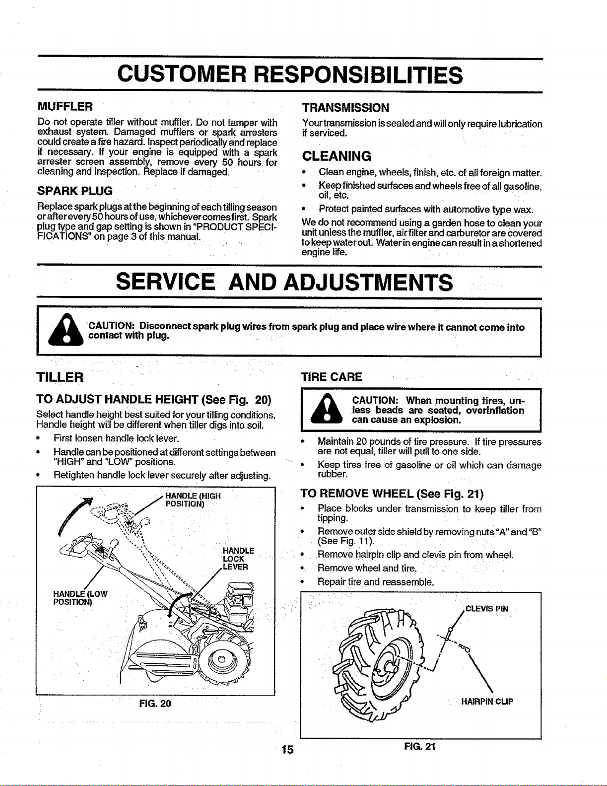
TO ADJUST HANDLE HEIGHT (See Fig. 20)
Select handle height best suited for your tilling conditions,
Handle height will be different when tiller digs into soi!.
• First loosen handle lock lever.
• Handte can be positioned at different settings between
"HIGH" and "LOW" positions,
• Retighten handle lock lever securely after adjusting.
._ HANDLE (HIGH
.... _-_, /POSITION)
"__'_\ ",,":_ LOCK
FIG. 20
TIRE CARE
_ i i iiii i Ill II1 I
CAUTION: When mounting tires, un-
less beads are seated, overinflation
can cause an explosion.
• Maintain 20 pounds of tire pressure, If tire pressures
are not equal, tiller will pull to one side.
• Keep tires free of gasoline or oil which can damage
rubber.
TO REMOVE WHEEL (See Fig. 21)
• Place blocks under transmission to keep tiller from
tipping.
• Remove outer side shield by removing nuts"A" and "B"
(See Fig. 11).
• Remove hairpin clip and clevis pin from wheel.
• Remove wheel and tire.
• Repair tire and reassemble.
CLEVIS PIN
1 HAIRPINCLIP
15 FIG. 21
SERVICE AND ADJ
i i iiiiiiiiii ii IIIIII!,,I,I,IIIIIHIIIIIHII,,IIII!IIIII,
NTS :
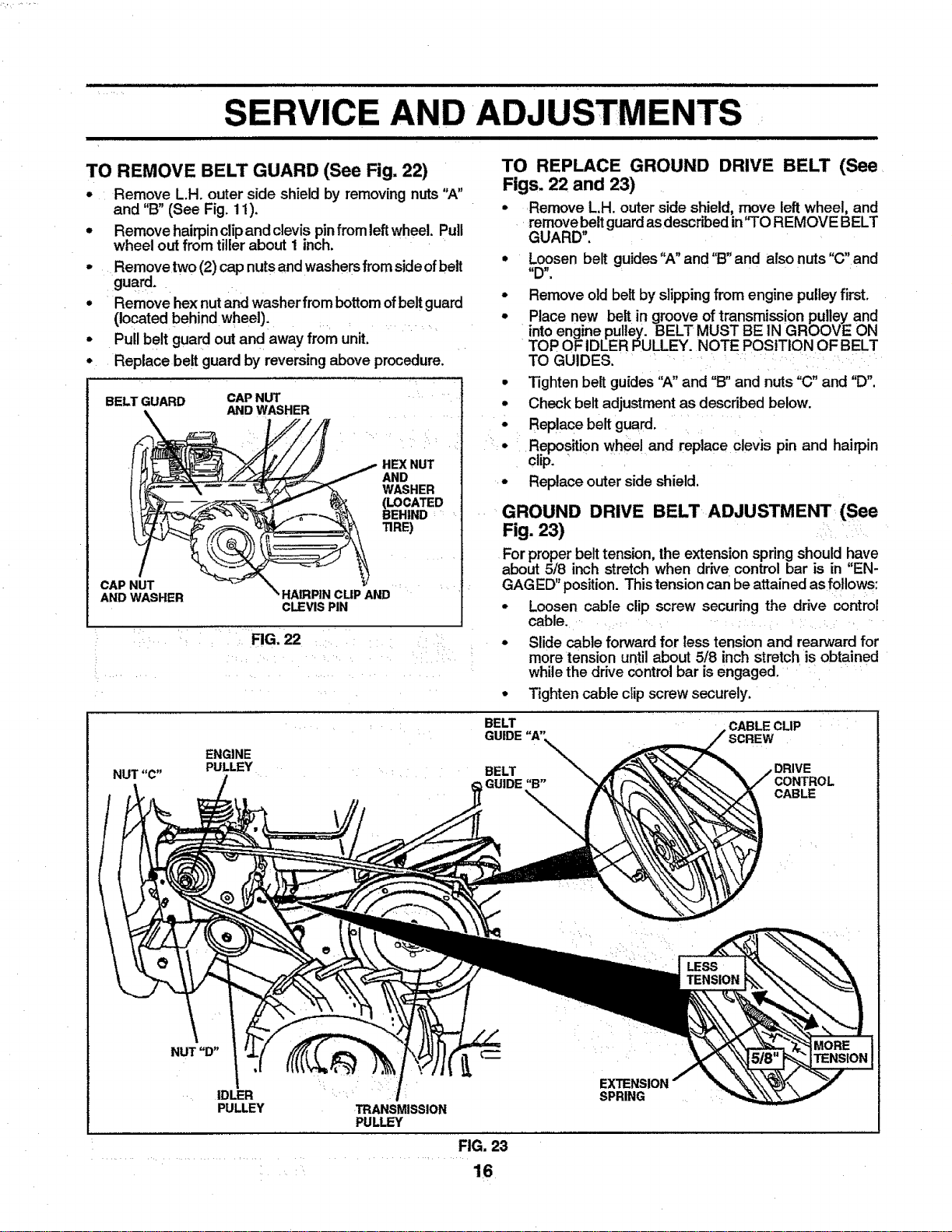
TO REMOVE BELT GUARD (See Fig. 22)
• Remove LH. outer side shield by removingnuts "A"
and "B" (See Fig. 11).
• Removehairpinclipandctevis p!nfrom leftwheel. Pull
wheel out from tillerabout 1 inch.
Remove two (2) capnutsand washersfrom side ofbelt
guard.
Remove hexnut andwasher from bottom ofbelt guard
(located behind wheel).
Pull belt guard out and away from unit.
Replace belt guard by reversingabove procedure.
BELT GUARD CAP NUT
AND WASHER
HEX NUT
AND
WASHER
(LOCATED
BEHIND
TIRE)
CAP NUT
AND WASHER
AND
CLEVIS PIN
FIG. 22
TO REPLACE GROUND DRIVE BELT (See
Figs. 22 and 23)
• Remove L,H. outer side shield, move leftwheel, and
remove beltguardas describedin"TO REMOVE BELT
GUARD".
o
o
o
: •
Loosen belt guides"A" and "B"and alsonuts "C" and
Remove old belt by slipping from engine pulley first,
Place new belt in groove of transmission pulley and
intoengine pulley. BELT MUST BE IN GROOVE ON
TOP OF IDLER PULLEY. NOTE POSITION OF BELT
TO GUIDES. .....
Tightenbelt guides "A"and =B"and nuts "C" and "D'.
Check beltadjustment as describedbelow.
Replace belt guard.
Repositionwheel and replace clevis pin and hairpin
clip. "
Replace outer side shield,
GROUND DRIVE BELT ADJUSTMENT (See
Fig. 23)
For properbelttension, the extension springshould have
about 5/8 inch stretch when drive control bar is in "EN-
GAGED"position. Thistensioncan beattainedas fotlows:
• Loosen cable clip screw securing the drive control
cable.
• Slide cable forward for less tension and rearward for
more tension until about 5/8 inch stretch is obtained
while the drive control bar isengaged,
• Tighten cable clip screw securely.
BELT
CABLECLIP
ENGINE
PULLEY
BELT
GUIDE"B"
\
DRIVE
CONTROL
CABLE
LESS
TENSION
IDLER
PULLEY
TRANSMISSION
PULLEY
SPRING
FIG. 23
16
SERVICE AND ADJUSTM
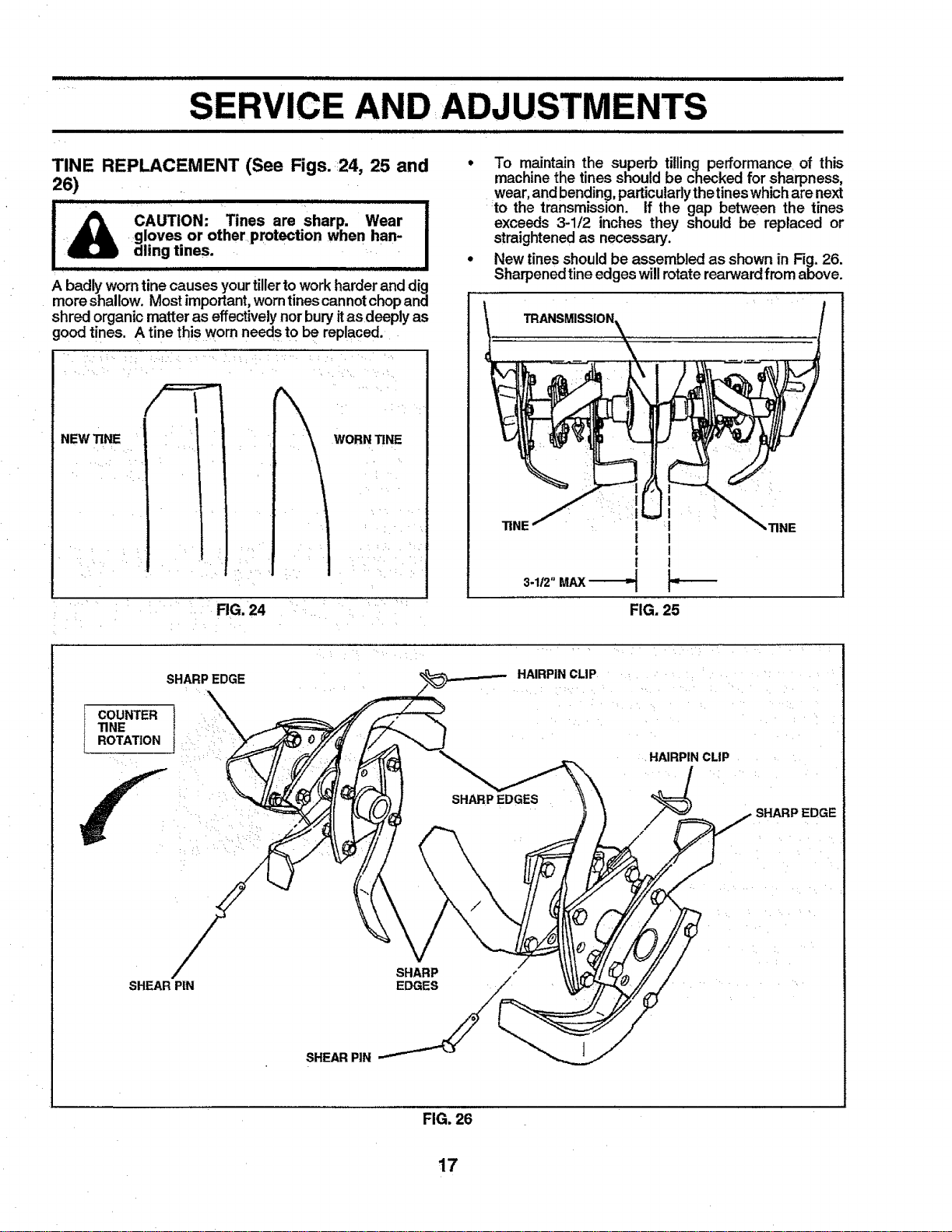
TINE REPLACEMENT (See Figs. 24, 25 and
26)
CAUTION: Tines are sharp. Wear
gloves or other protection when han-
dling tines.
IIlI IiI]l II II J] IIII Ill IIlIliII
A badly worntine causes your tillerto workharder and dig
more shallow. Most important, worn tines cannot chopand
shred organic matter as effectively norbury itas deeply as
good tines. A tine this worn needs to be replaced.
NEW TiNE WORN TiNE
!,I
• /!
FIG. 24
To maintain the superb tilling performance of this
machine the tines should be checked for sharpness,
wear, and bending, particularlythetines which are next
to the transmission. If the gap between the tines
exceeds 3-1/2 inches they should be replaced or
straightened as necessary.
New tines should be assembled as shown in Fig. 26.
Sharpenedtine edges will rotate rearward from above.
I I
"FINE I I
! I
! I
I I
3.1/2"MAX -_
TINE
FIG. 25
SHARPEDGE
HAIRPIN CLIP
COUNTER t
TINE
ROTATION :
i :
f i
SHARP EDGES
HAIRPIN CLIP
EDGE
SHEAR PiN
SHARP -"
EDGES /
SHEAR PIN "__
FIG. 26
17
i i illll i elm i iiill,lllll,i LL ,,IIIMI I II Ill=1 I Ill I1 Ill I,I I
AND ADJUSTMENTS
IIIH,illii,lllll i wl ,,,Hii ii i i i i
ENGINE ........
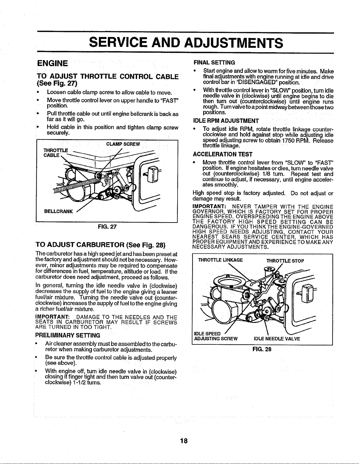
TO ADJUST THROTrLE CONTROL CABLE
(See Fig. 27)
• Loosen cable clamp screw to allowcable to move.
° Move throttle control lever on upper handleto "FAST"
position.
- Pullthrottlecable out untilengine bellcrank isback as
far as it willgo.
° Hold cable in this position and tighten clamp screw
securely.
CLAMPSCREW _ :
THROTTLE
CABLE
BELLCRANK
FIG. 27
TO ADJUST CARBURETOR (See Fig. 28)
The carburetor has a high speed jet and hasbeen presetat
the factory and adjustment should not be necessary. How-
ever, minor adjustments may be required to compensate
for differences in fuel, temperature, altitude or load. If the
carburetor does need adjustment, proceed as follows.
In general, turning the idle needle valve in (clockwise)
decreases the supply of fuel to the engine giving a leaner
fuel/air mixture. Turning the needle valve out (counter-
clockwise) increases the supply of fuel to the engine giving
a richer fuel/air mixture.
IMPORTANT: DAMAGE TO THE NEEDLES AND THE
SEATS IN CARBURETOR MAY RESULT IF SCREWS
ARE TURNED IN TOO TIGHT.
PRELIMINARY SE'n'iNG
• Air cleaner assembly mustbe assembled to thecarbu-
retor when making carburetor adjustments.
• Be sure the throttle control cable isadjusted properly
(see above).
• With engine off, turn idle needle valve in (clockwise)
closing itfinger tight and then turn valve out (counter-
clockwise) 1-1/2 turns.
FINAL SETTING
• Startengine and allow to warmfor five minutes. Make
final adjustments with engine running at idleand drive
control bar in 'I_ISENGAGED" positmon.
° With throttle controllever in =SLOW" position, turn idle
needle valve in (clockwise) until engine begins to die
then turn out (counterclockwise) until engine runs
rough. Turn valve to a point midway between those two
positions.
IDLE RPM ADJUSTMENT
• To adjust idle RPM, rotate throttle linkage counter-
clockwiseand hold against stop while adjusting idle
speed adjustingscrewto obtain 1750 RPM. Release
throttlelinkage.
ACCELERATION TEST
,, Move throttle control lever from "SLOW" to "FAST"
position,if engine hesitatesor dies,turnneedle valve
out (counterclockwise) 1/8 turn. Repeat test and
continuetoadjust, ifnecessary, until engine acceler-
ates smoothly.
High speed stop is factory adjusted. Do not adjust or
damage may result.
IMPORTANT: NEVER TAMPER WITH THE ENGINE
GOVERNOR, WHICH IS FACTORY SET FOR PROPER
ENGINE SPEED. OVERSPEED[NG THE ENGINE ABOVE
THE FACTORY HIGH SPEED SETTING CAN BE
DANGEROUS. IF YOUTHINK THE ENGINE-GOVERNED
HIGH SPEED NEEDS ADJUSTING, CONTACT YOUR
NEAREST SEARS SERVICE CENTER, WHICH HAS
PROPEREQUIPMENT AND EXPERIENCE TO MAKEANY
NECESSARY ADJUSTMENTS.
THROTTLE UNKAGE
THROTTLE STOP
IDLE SPEED
ADJUSTING SCREW IDLE NEEDLE VALVE
FIG. 28
18
Immediately prepare your tiller for storage at the end of the
season or ifthe unit will not be used for 30 days or more.
i i
CAUTION: Never store the tiller with
gasoline in the tank inside a building
where fumes may reach an open flame
or spark. Allow the engine to cool
before storing in any enclosure.
| i ] Ill
• Clean entire tiller (See "CLEANING" in the Customer
Responsibilitiessectionofthis manual)_
° Inspect and replace belts, if necessary (See belt re-
placement instructions in the Service and Adjustments
section of this manual), i
• Lubricate as shown in the Customer Responsibilities
section of this manual. ......
• Be sure that all nuts, bolts and screws are securely
fastened. Inspect moving partsfor damage, breakage
and wear. Replace if necessary.
• Touch up all rusted or chipped paint surfaces; sand
lightly before painting.
ENGINE
FUEL SYSTEM
IMPORTANT: iT IS IMPORTANT TO PREVENT GUM
DEPOSITS FROM FORMING IN ESSENTIAL FUEL
SYSTEM PARTS SUCH AS THE CARBURETOR, FUEL
FILTER, FUEL HOSE, OR TANK DURING STORAGE.
ALSO, EXPERIENCE INDICATES THAT ALCOHOL
BLENDED FUELS (CALLED GASOHOL OR USING
ETHANOL OR METHANOL) CAN ATTRACT MOISTURE
WHICH LEADS TO SEPARATION AND FORMATION OF
ACIDS DURING STORAGE. ACIDIC GAS CAN DAMAGE
THE FUEL SYSTEM OFAN ENGINE WHILE IN STORAGE.
• Drain the fuel tank,
• Start the engine and let it run until the fuel lines and
carburetor are empty.
• Never use engine orcarburetor cleaner products inthe
fuel tank or permanent damage may occur.
• Use fresh fue! next season.
NOTE: Fuel stabilizer is an acceptable alternative in
minimizing the formation of fuel gum deposits during stor-
age. Add stabilizer to gasoline in fuel tank or storage
container. Always follow the mix ratio found :on stabilizer
container. Run engine at least 10 minutes after adding
stabilizer to allowthe stabilizer to reach the carburetor. Do
notdrain the gastank and carburetor ifusing fuel stabilizer.
ENGINE OIL
Drain oil (with engine warm) and replace with clean oil.
(See "ENGINE" inthe Customer Responsibilities section of
this manual).
CYLINDERS
• Remove spark plug.
° PourI ounce (29 ml)of oil through spark plug hole into
cylinder. .... :
• Pullstarterhandleslowlyseveraltimestodistributeoil.
• Replacewith new spark plug.
OTHER
• Do not store gasoline from one season to another.
• Replace your gasoline can if your can starts to rust.
Rust and/or dirt in your gasoline will cause problems.
• if possible, store your unit indoors and cover it to give
protection from dust and dirt.
• Cover your unit with a suitable protective cover that
does not retain moisture. Do not use plastic. Plastic
cannot breathe which allows condensation to form and
will cause your unit to rust.
IMPORTANT: NEVER COVER TILLER WHILE ENGINE
AND EXHAUST AREAS ARE STILL WARM.
19
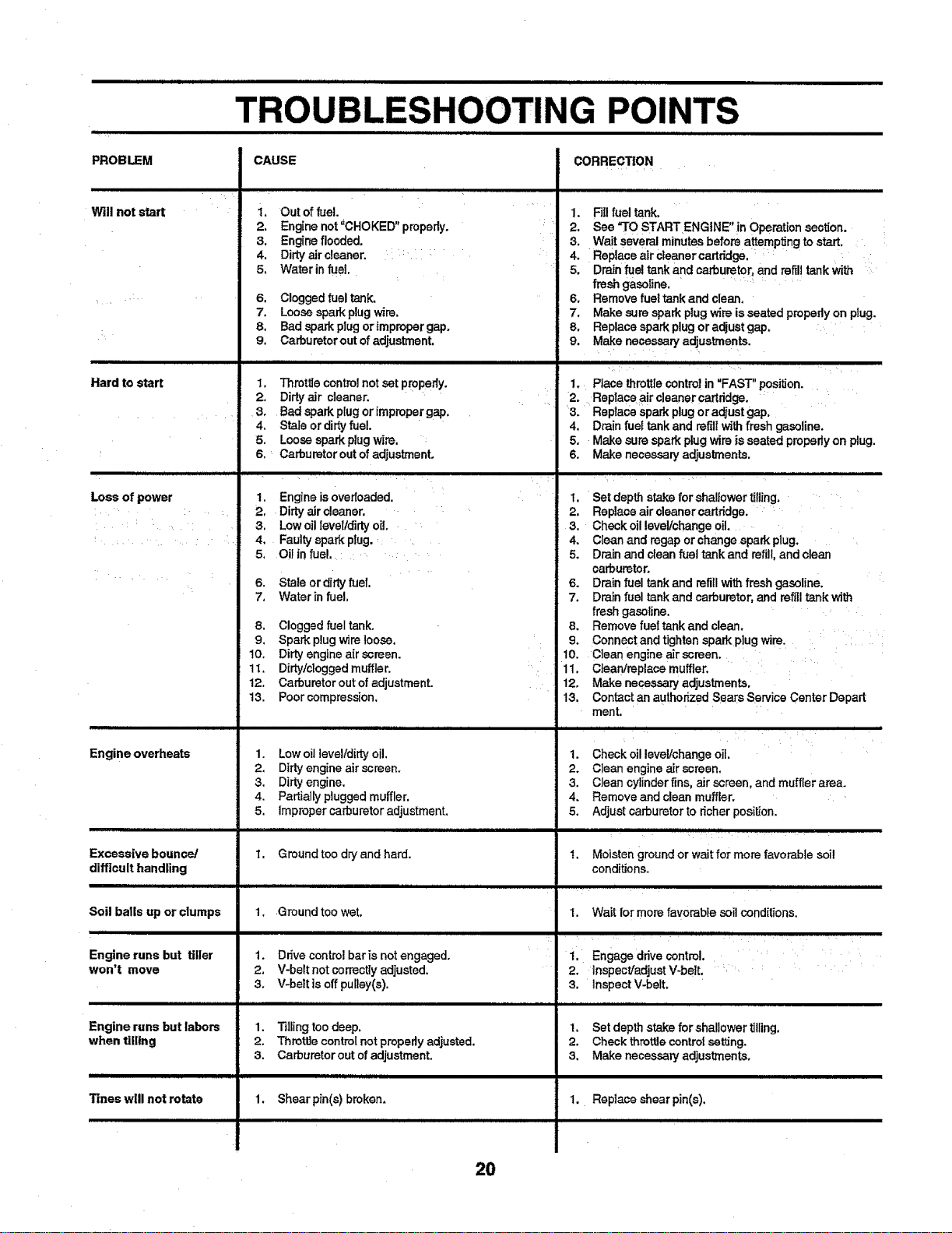
TROU NG POINTS
Illll I IIIIIIIIIIIIIIIIIIII IIIIII IIII IIIIIII1[I I I IJ IIL[IIIUIIIII I II I II11111 II I I
CAUSE CORRECT|ON
PROBLEM
i
Will not start
Hard to start
ii,lll ii i ii llllllll.=ll
Loss of power
Engine overheats
Excessive bounce/
difficult handling
lllliH i i i i i
Soil balls up or clumps
i iH
Engine runs but tiller
won't move
Engine runs but labors
when tilling
Tineswill notrotate
• H IlllIIlll,ll I I I •1 I
i. Out of fue!.
2. Engine not _CHOKED" properly.
3. Engine flooded.
4. Dirty air cleaner. : i :
5, Water in fuel
6, Cloggedfueltank.
7, Loosesparkplug wire.
8. Badsparkplugorimpropergap,
9. Carburetoroutofadjustment.
1. Throttlecontrefnot setproperly,
2, Dirtyair cleaner.
3, Badsparkplugorimpropergap,
4. Staleor dirtyfuel.
5. Loosesparkplugwire.
6, _Carburetoroutof adjustment,
UHIHIJIIHIJNIIII :
1, Engine isOverloaded.
2. Dirty air cleaner.
3. Low oil feveltdirtyo[I.
4. Faulty spark plug. :_
5. Oil in fuel. ......
6. Stale or dirtyfuel.
7. Water in fuel.
8. Clogged fuel tank.
9. Spark plugwire loose.
10. Dirty engine a[r screen.
11. Dirb!/clogged muffler.
12. Carburetor outof adjustment.
13. Poor compression.
1. Low oil level/dirty oil.
2. Dirty engine air screen.
3. Dirty engine.
4. Partially ptugged muffler.
5. Improper carburetor adjustment.
I. Ground too dry and hard.
1..Ground too wet.
r.llfffllrnrmliHi i
1. Drive control bar is not engaged.
2. V-belt not correctly adjusted.
3. V-heir is offpulley(s).
1. Tilling too deep.
2. Throttle controlnot properlyadjusted.
3. Carburetor out of adjustment.
t.
2.
4,
5,
6.
7.
8,
9.
1.
Fillfuel tank,
See '3"0STARTENGtNE"in Operationsect[on,
.Waitseveralminutesbeforeattempt[ngtostart,
Replaceair cleanercartridge.
Drainfue!tank andcarburetor,andrefilltankwith
freshgasoline. ....
Removefueltankand clean.
Makesuresparkplugwire isseatedpropedyon plug.
Replacesparkplugor adjustgap_
Makenecesearyadjustments.
4,
5,
6.
Place throttlecontrolin "FAST" position.
Replace air cleaner cartridge.
Replace spark plug or adjust gap.
Drain fuet tank and refillwith fresh gasoline.
Make sure spark plugwire is seated properly on plug.
Make necessary adjuslments.
,,,],,,,,,,,,,,,,,,,, ,,,,,],,,,,,,,,,,,,,,,,,,,,,,, ,,,,,,,,
1. Set depth stake for shallower tilling,
2. Replace air cleanercartridge.
8. Check oil level/change oil.
4, Clean and rogap or change spark plug,
5. Drain and clean fuel tank and refill, and clean
carburetor.
6. Drain fuel tank and refillwit_ fresh gasoline.
7. Drain fuel tank and carburetor, and refilltank with
fresh gasoline.
8. Remove fuel tank and clean.
9, Connectand tighten sparkp!ug wire.
10. Clean engine air screen
11. Clean!replace muffler.
12. Make necessan] adjustments.
13. Contact an authorized Sears Service Center Depart
ment.
ill ill illll i i i i ii
1. Check oil leve!/change oiL
2. Clean engine air screen.
3. Clean cylinderfins, air screen, and muffler area.
4. Remove and clean muffler.
5. Adjust carburetor to richer position.
t.
.....,,, .,,,,,,,,, .,,,.,_
Moisten ground or waitfor more favorable soi!
conditions.
1. Wait for more favorable soil conditions.
i. Engage drive control.
2. lnspectladjust V-belt.
3. Inspect V-belt.
1, Shear pin(s) brokan.
.ill :_
1. Set depth stake for shallower tilling.
2. Check thret_e control set'ring.
5, Make necessary adjusttnenta,
1. Replace shear pin(s),
20
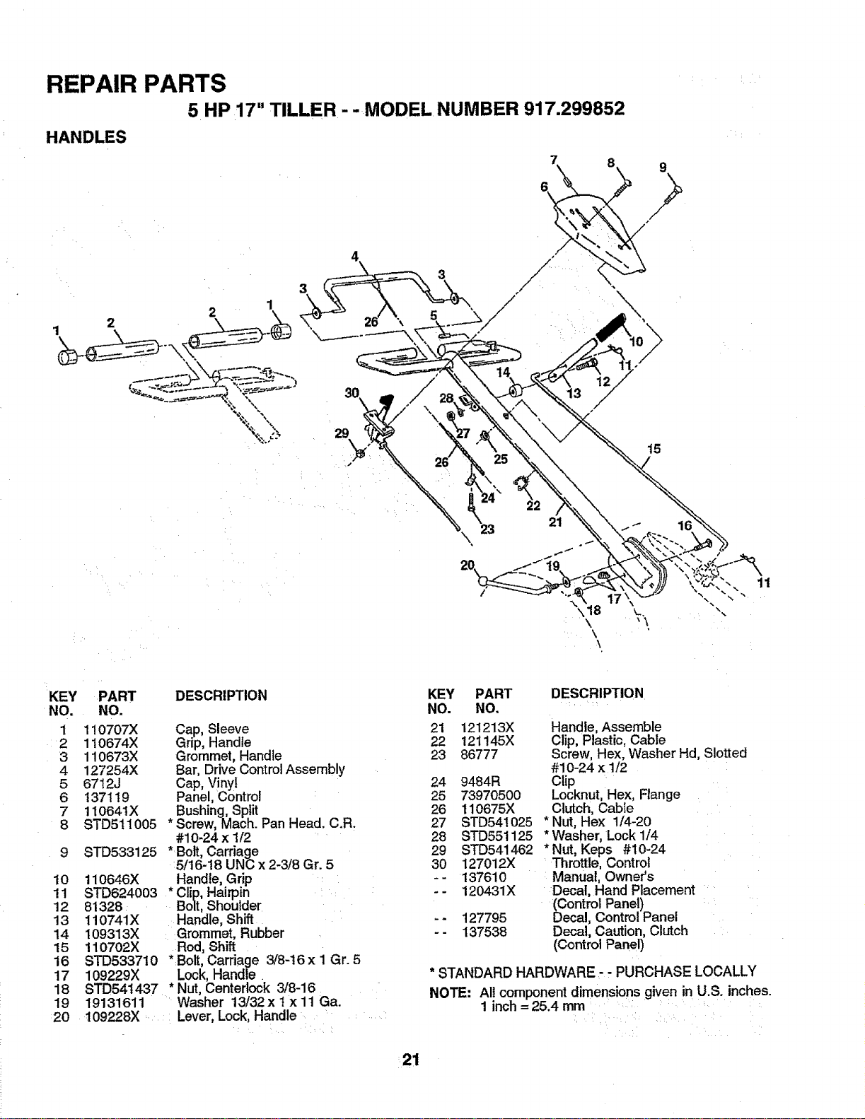
REPAIR PARTS
5 HP 17" TILLER-- MODEL NUMBER 917.299852
HANDLES
7
23
t5
11
KEY
NO.
1
2
3
4
5
6
7
8
lO
11
12
13
14
15
16
17
18
19
:20
PART
NO.
110707X
110674X
110673X
127254X
6712J
137119
11064t X
STD511005
STD533125
110646X
DESCRIPTION
Cap, Sleeve
Grip, Handle
Grommet, Handle
Bar, Drive Control Assembly
Cap, Vinyl
Panel, Control
Bushing, Split
* Screw, Mach. Pan Head. C.R.
#10-24 x 1/2
*Bolt, Carriage
:5/16-18 UNC x 2-3/8 Gr. 5
Handle, Grip
STD624003 *Clip, Hairpin
81328 Bolt, Shoulder
t10741X
109313X
110702X
8TD533710
109229X
STD541437
19131611
109228X,
:Handle, Shift
: Grommet, Rubber
Rod, Shift
*Bolt, Carriage 3/8-16 x I Gr. 5
Lock, Handle.
* Nut, Centerlock 3/8-16
' Washer 13/32 x t x 11 Ga.
Lever, Lock,Handle ...... :
KEY
NO.
21
22
23
24
25
26
27
28
29
3O
.=
PART DESCRIPTION
NO.
121213X Handle, Assemble
121145X Clip, Plastic, Cable
86777 Screw, Hex, Washer Hd, Slotted
#10-24 x 1/2
9484R Clip
73970500 Locknut, Hex, Flange
110675X Clutch, Cable
STD54t025 * Nut, Hex 1/4-20
STD551125 * Washer, Lock 1/4
STD541462 *Nut, Keps #10-24
127012X Throttle, Control
137610 Manual, Owner's
120431X Decal, Hand Placement
(Control Panel)
127795 Decal, Control Panel
137538 Decal, Caution, Clutch
(Control Panel)
* STANDARD HARDWARE - - PURCHASE LOCALLY
NOTE; All component dimensions given in U.S. inches.
1 inch = 25.4 mm
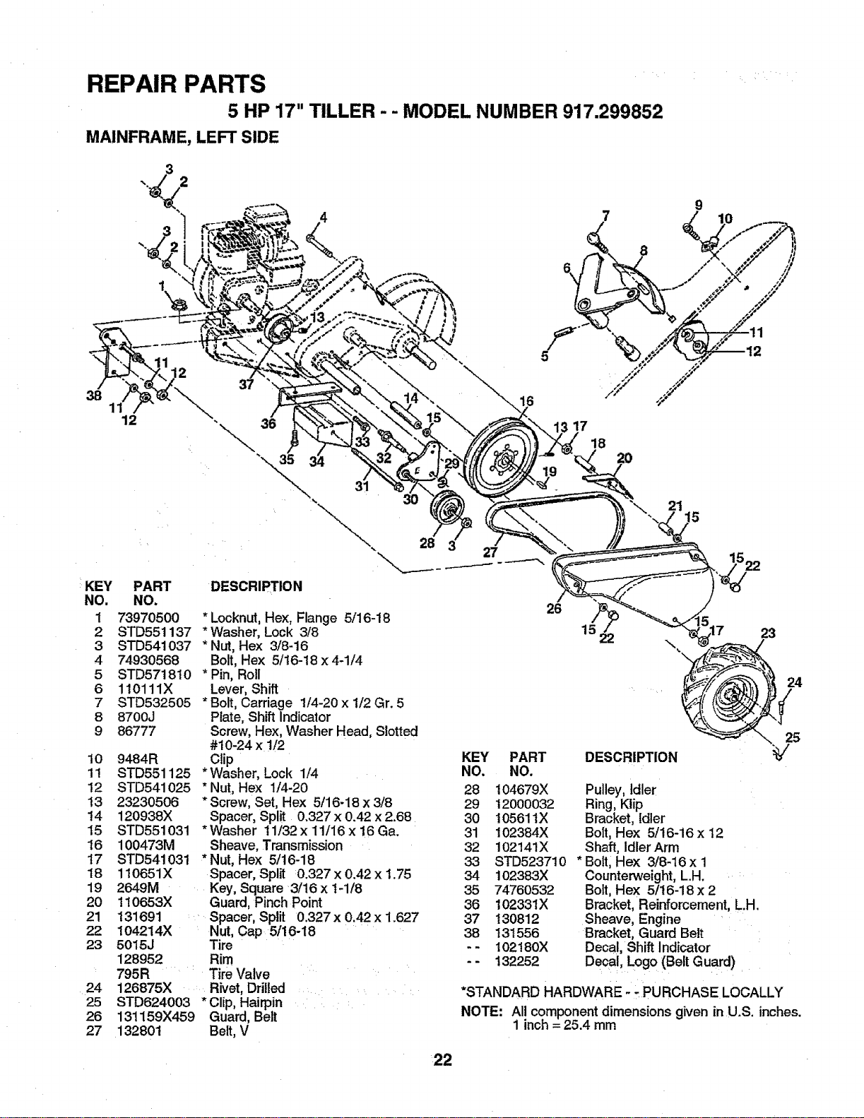
REPAIR PARTS
5 HP 17" TILLER - - MODEL NUMBER 917.299852
MAINFRAME, LEFT SIDE
12
37
38 16
11
12 36
KEY PART
NO. NO.
1 73970500
2 STD551137
3 STD541037
4 74930568
5 STD57t810
6 110111X
7 STD532505
8 8700J
9 86777
10 9484R
tl STD551125
12 STD541025
t3 23230506
14 120938X
15 STD551031
16 100473M
t7 STD54i031
18 110651X
19 2649M
20 110653X
21 131691
22 104214)(
23 5015J
128952
795R
24 126875)(
25 STD624003
26 131159X459
27 132801
17
18
2O
8
31
21
15
28
DESCRIPTION
* Locknut,Hex, Flange 5/16-18
* Washer, Lock 3/8
* Nut, Hex 3/8-16
Bolt, Hex 5/16-18 x 4-1/4
* Pin, Roll
Lever, Shift
* Bolt, Carriage 1/4-20 x 1/2 Gr. 5
Plate, Shift Indicator
Screw, Hex, Washer Head, Slotted
#10-24 x 1/2
Clip
*Washer, Lock 1/4
* Nut, Hex 114-20
*Screw, Set, Hex 5/16-18 x 3/8
Spacer, Split 0.327 x 0.42 x 2.68
*Washer 11/32x 11/16x 16Ga.
Sheave, Transmission
*Nut, Hex 5/16-18
Spacer, Split 0.327 x 0.42 x 1.75
Key, Square 3/16 x t-1/8
Guard, Pinch Point
Spacer, Split 0.327 x 0.42 x 1.627
Nut, Cap 5!16-18
Tire
Rim
Tire Valve
.... Rivet, Drilled ......
* Clip, Hairpin
Guard, Belt
Belt, V
26
KEY PART
NO. NO.
28 104679X
29 12000032
30 10561tX
31 102384X
32 102141X
33 STD523710
34 102383X
35 74760532
36 10233tX
37 130812
38 13t556
- - 102!80X
132252
23
,Q
24
25
DESCRIPTION
Pulley, Idler
Ring, Kiip
Bracket, Idler
Bolt, Hex 5/16-16 x 12
Shaft, Idler Arm
* Boitl Hex 3/8-16 x 1
Counterweight, L.H.
Bolt Hex 5/16-18 x 2
Bracket, Reinforcement, L.H.
Sheave, Engine
Bracket, Guard Belt
Decal, Shift Indicator
-- Decal, Logo (Belt Guard)
*STANDARD HARDWARE- -PURCHASE LOCALLY
NOTE" All component dimensions given inU.S. inches.
1 inch = 25.4 mm
22
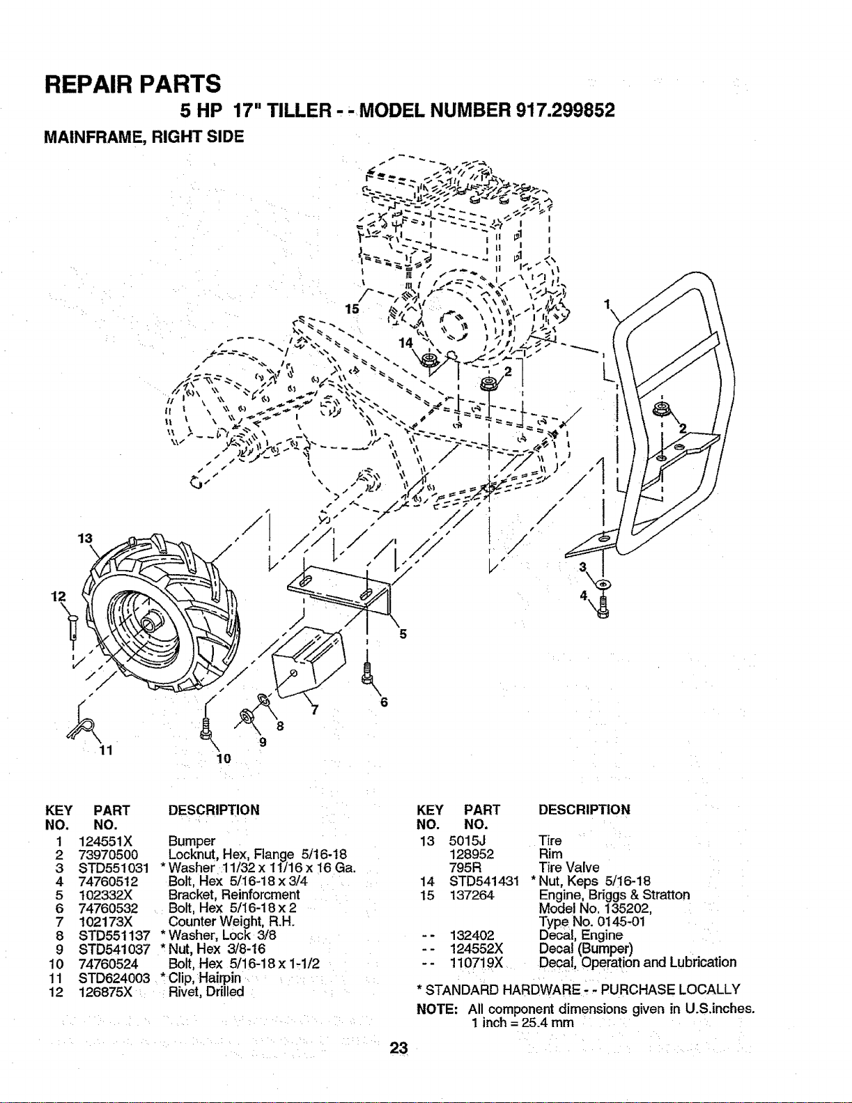
REPAIR PARTS
5 HP 17" TILLER. ,MODEL NUMBER 917.299852
MAINFRAME, RIGHT SIDE
12
13
V
11
%
5
I
\
6
KEY
NO.
t
2
3
4
5
6
7
8
9
10
1t
12
PART
NO.
124551X
73970500
8TD551O31
74760512
102332X
74760532
1O2173)(
STD551137
STD541 O37
74760524
STD624003
126875X
DESCRIPTION
Bumper
Locknut, He)(, Flange 5/16-18
*Washer 11/32 x 11J16x 16 Ga.
Bolt, Hex 5/16-18 x 3/4
Bracket, Reinforcment
Bolt, Hex 5/16-18 x 2
Counter Weight, R.H.
*Washer, Lock 3/8
* Nut, He]< 3/8-16
Bolt, Hex 5/16-18x 1-1/2
*Clip, Hairpin
Rivet, Drilled
23
KEY
NO.
13
14
15
.I
PART
NO.
5015J
128952
795R
STD541431
137264
1324O2
124552X
!107i9X
DESCRIPTION
Tire
Rim
Tire Valve
*Nut, Keps 5/!6-18
Engine, Briggs& Stratton
Model No. 135202,
Type No. 0145.01
ecal, Engine
Decal (Bumper)
Decal, Operation and Lubrication
* STANDARD HARDWARE ;;PURCHASE LOCALLY
NOTE: All component dimensions given in U.S.inches.
I inch= 25.4 mm
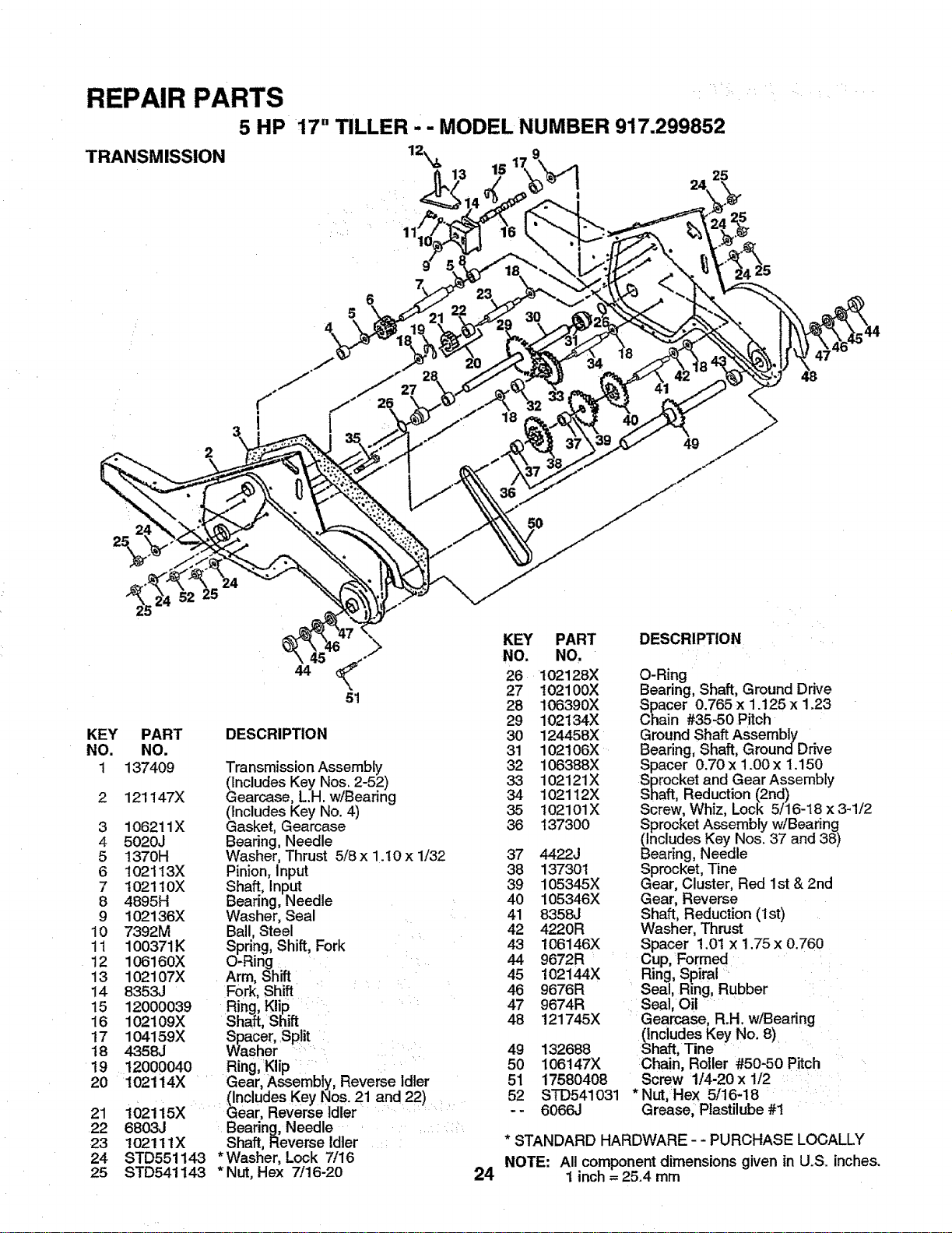
REPAIR PARTS :
5 HP 17" TILLER - - MODEL NUMBER 917.299852
TRANSMISSION
24
25
18
49
KEY
NO.
1
2
3
4
5
6
7
8
9
10
11
12
13
14
15
16
17
18
19
20
21
22
23
24
25
PART DESCRIPTION
NO.
137409 Transmission Assembly
(Includes Key Nos. 2-52)
121147)( Gearcase, L.H. w/Bearing
(Includes Key No. 4)
106211X Gasket, Gearcase
5020J Bearing, Needle
1370H Washer, Thrust 5/8 x 1.!0 x 1/32
102113X Pinion, Input
102110X Shaft, Input
4895H Bearing, Needle
102136X Washer, Seal
7392M Ball, Steel
100371K Spring, Shift, Fork
106160X O-Ring
102107X Arm, Shift
8353J Fork, Shift
12000039 Ring, Klip
102109X Shaft, Shift
104159X Spacer, Split
4358J Washer :
12000040 Ring, Klip i:
102114X .......Gear, Assembly, Reverse Idler
(Includes Key Nos. 21 and 22)
i02115X Gear, Reverse Idler ..... ....
6803J Bearing, Needle ........
102111X Shaft, Reverse Idler
STD551143 * Washer, Lock 7/16
STD541143 * Nut, Hex 7/16-20 24
KEY PART
NO. NO,
26 102128X
27 102100X
28 106390X
29 102134X
30 124458)(
31 102t06X
32 106388X
33 102121X
34 102112X
35 102101X
36 137300
37 4422J
38 137301
39 105345X
40 105346X
41 8358J
42 4220R
43 106146X
44 9672R
45 !02144X
46 9676R
47 9674R
48 121745X
49 132688
50 106147X
51 17580408
52 STD541031
-- 6066J
DESCRIPTION
O-Ring
Bearing, Shaft, Ground Drive
Spacer 0.765 x 1.125 x 1.23
Chain #35-50 Pitch
Ground Shaft Assembly
Bearing, Shaft, GroundDrive
Spacer 0.70 x 1.00 x 1.150
Sprocket and Gear Assembly
Shaft, Reduction (2rid)
Screw, Whiz, Lock 5/16-18 x 3-1/2
Sprocket Assembly w/Bearing
(Includes Key Nos. 37 and 38)
Bearing, Needle
Sprocket, Tine
Gear, Cluster, Red 1st & 2nd
Gear, Reverse
Shaft, Reduction (1st)
Washer, Thrust
Spacer 1.0t x 1.75 x 0.760
:Cup, Formed
Ririg, Spiral
Seal, Ring, Rubber
Seal, O!l
Gearcase, R.H. w/Bearing
(Includes Key No. 8)
Shaft, Tine
Chain, Roller #50-50 Pitch
Screw 1/4-20 x 1/2 :: '
* Nut,Hex 5/16-18
Grease, Plastilube #1
* STANDARD HARDWARE - - PURCHASE LOCALLY
NOTE: All component dimensions given in U.S. inches.
1 inch = 25.4 mm
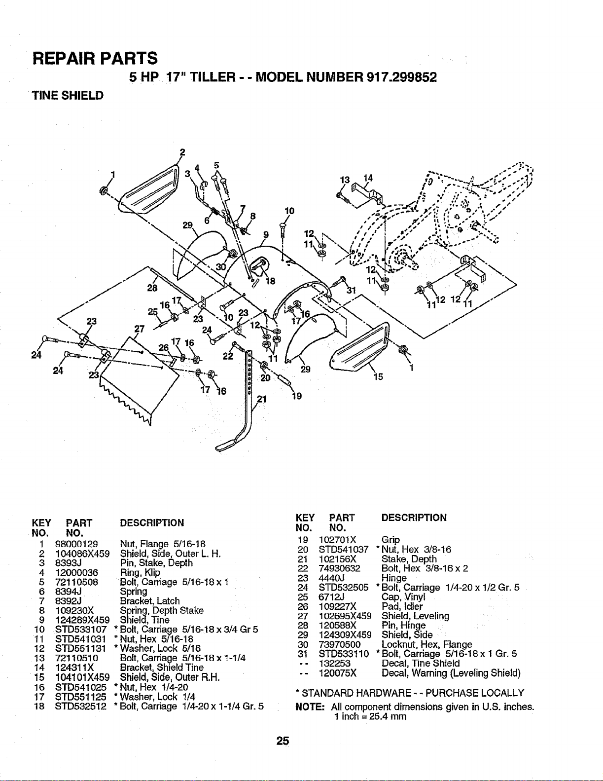
REPAIR PARTS
5 HP 17" TILLER - - MODEL NUMBER 917.299852
TINE SHIELD
8
9
10
24
<_ 23
24
28
21
\
19
15
KEY
NO.
1
2
3
4
5
6
7
8
9
10
11
12
13
14
15
16
17
18
PART
NO.
98000129
104086X459
8393J
12000036
72110508
8394J
8392J
109230X
124289X459
STD533107
STD541031
STD551131
7211O51O
124311X
!04101X459
STD541025
STD551125
STD532512
DESCRIPTION
Nut, Flange 5/16-18
Shield, Side, Outer L. H.
Pin, Stake, Depth
Ring, Klip
Bolt, Carriage 5/16-18x 1
Spring
Bracket, Latch
Spring, Depth Stake
Shield, Tine
* Bolt, Carriage 5/16,18 x 3/4 Gr 5
* Nut, Hex 5/16-18
* Washer, Lock 5/16
Bolt, Carriage 5/16-18 x 1-1/4
Bracket, ShieldTine
Shield, Side, Outer R.H.
* Nut, Hex 1/4-20
* Washer, Lock 1/4
* Bott, Carriage 1/4-20 x 1-1/4 Gr. 5
KEY PART DESCRIPTION
NO. NO.
19 102701X Grip
20 STD541037 * Nut, Hex 3/8-t6
21 102156X Stake, Depth
22 74930632 Bolt, Hex 3/8-16 x 2
23 4440J Hinge
24 STD532505 * Bolt,Carriage 1/4-20 x 1/2 Gr. 5
25 6712J Cap, Vinyl
26 109227X Pad, Idler
27 102695X459 Shield, Leveling
28 120588X Pin, Hinge
29 124309X459 Shield, Side .'
30 73970500 Locknut,Hex, Flange
31 STD533t10 * Bolt, Carriage 5/16-18x 1 Gr. 5
- - 132253 Decal, Tine Shield
- - 120075X Decal, Warning (Leveling Shield)
* STANDARD HARDWARE - - PURCHASE LOCALLY
NOTE: All component dimensions given in U.S. inches.
1 inch = 25.4 mm
25
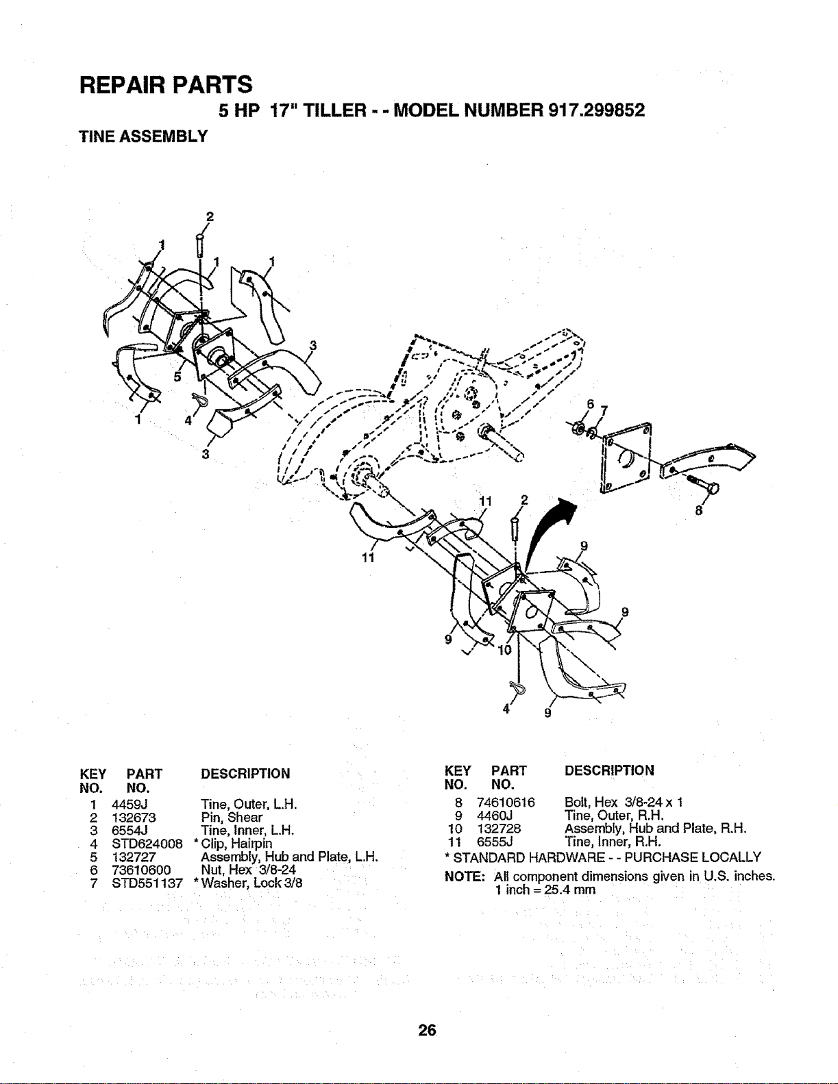
REPAIR PARTS
5 HP
TINE ASSEMBLY
17" TILLER - - MODEL NUMBER 917.299852
1
3
3
11 2
11
9
4 9
KEY
NO.
1
2
3
4
5
6
7
PART
NO.
4459J
132673
6554J
STD624008
132727
736t 0600
STD551137
DESCRIPTION
Tine, Outer, L.H.
Pin, Shear
Tine, Inner, L.H.
*Clip, Hairpin
Assembly, Hub and Plate, L.H.
Nut, Hex 3/8-24
*Washer, Lock 3/8
KEY PART DESCRIPTION
NO. NO.
8 74610616 Bolt, Hex 3/8-24x 1
9 4460J Tine, Outer, R.H.
10 132728 Assembly, Hub and Plate, R.H.
11 6555J Tine, Inner, R.H.
* STANDARD HARDWARE - - PURCHASE LOCALLY
NOTE: All component dimensions given in U.S. inches.
1 inch= 25.4 mm
26
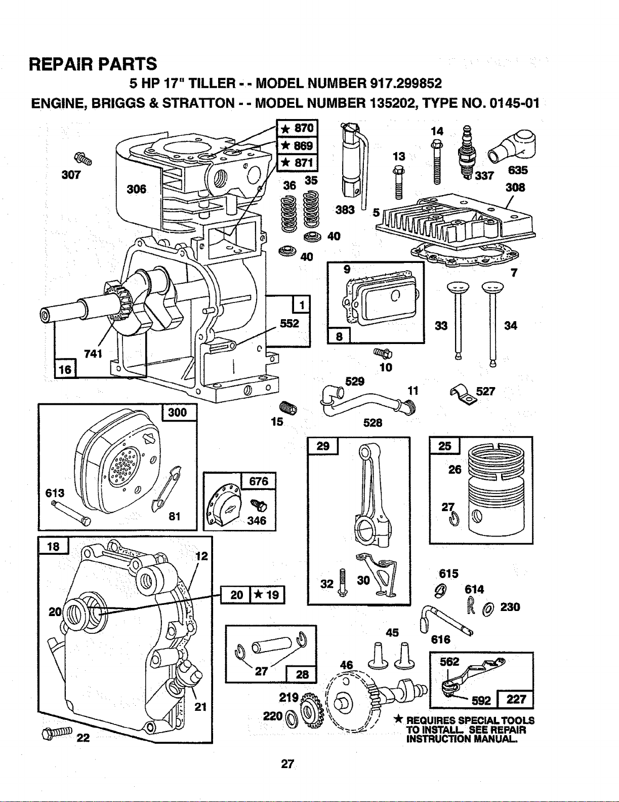
REPAIR PARTS
5 HP 17" TILLER - - MODEL NUMBER 917.299852
ENGINE, BRIGGS & STRATTON - - MODEL NUMBER 135202, TYPE NO. 0145-01
H
307
613
15
10
529
528
14
7
"k REQUIRES SPECLALTOOLS
TO INSTALL SEE REPAIR
INSTRUCTION MANUAL,
27
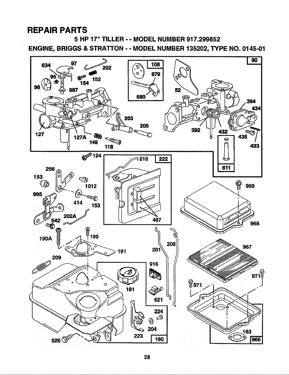
REPAIR PARTS
5 HP 17" TILLER - - MODEL NUMBER 917.299852
ENGINE, BRIGGS & STRATTON - - MODEL NUMBER 135202, TYPE NO. 0145-0i
.......... ::_:i ¸
118
124
J
394
. )
432-" . .,._
433
611
m
_969
467 8
Ol
2 7
621
224
204
223
28
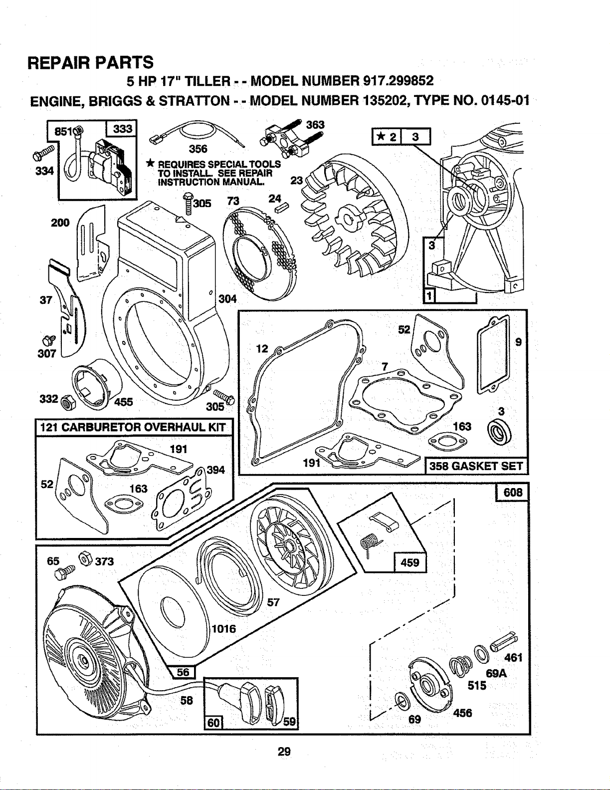
REPAIR PARTS
5 HP 17" TILLER. - MODEL NUMBER 917.299852
ENGINE, BRIGGS & STRATTON .-MODEL NUMBER 135202, TYPE NO. 0145-01
334
200
3o°
REQUIRES SPECIAL TOOLS
TO INSTALL SEE REPAIR
INSTRUCTION MANUAL. 23
7a 2_
37
307
332
121 CARBURETOR OVERHAUL KIT
191
163
3
163
lassGASKETsET
V
69
69A
515
456
29
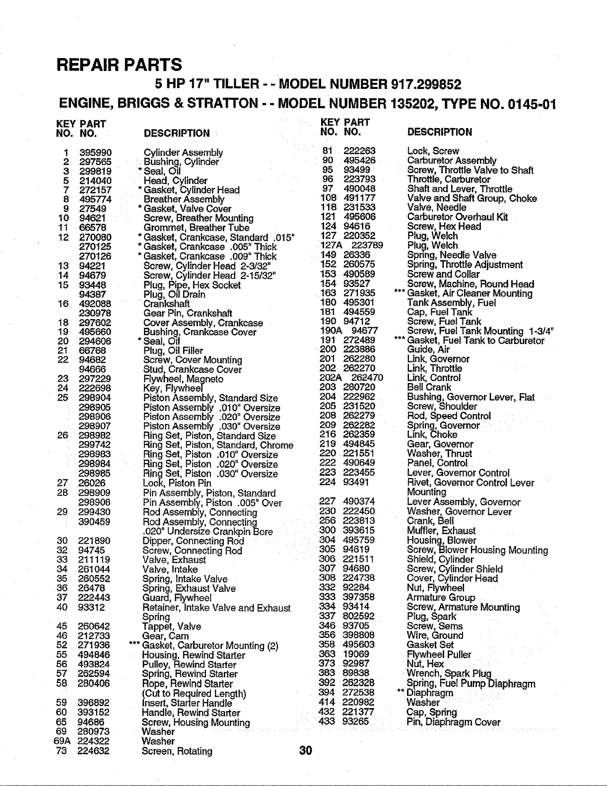
REPAIR PARTS
5 HP 17" TILLER -- MODEL NUMBER 917.299852
ENGINE, BRIGGS & STRATTON -- MODEL NUMBER 135202, TYPE NO. 0145-01
KEY PART
NO. NO. DESCRIPTION
1 395990
2 297565
3 299819
5 214040
7 272157
8 495774
9 27549
10 94621
11 66578
12 270080
270125
270t26
13 94221
14 94679
15 93448
94387
16 492088
230978
18 297602
19 495660
20 294606
21 66768
22 94682
94666
23 297229
24 222698
25 298904
' 298905
298906
298907
26 298982
299742
298983
298984
298985
27 26026
28 298909
298908
29 29943O
390459
30 22t 890
32 94745
33 21 t 119
34 26t 044
35 260552
36 26478
37 222443
40 933!2
45 260642
46 212733
52 271936
55 494846
56 493824
57 262594
58 280406
DESCRIPTION
Cylinder Assembly
BLishing,Cylinder
:*Seal, Oil
, Head, Cylinder
Gasket, Cylinder Head
Breather Assembly
*Gasket, Valve Cover
Screw, Breather Mounting
Grommet, BreatherTube
* Gasket, Crankcase, Standard .015"
* Gasket, Crankcase .005" Thick
* Gasket, Crankcase .009" Thick
Screw, Cylinder Head 2-3/32"
Screw, Cylinder Head 2-15/32"
Plug, Pipe, Hex Socket
Plug, Oil Drain
Crankshaft
Gear Pin, Crankshaft
Cover Assembly, Crankcase
Bushing, Crankcase Cover
* Seal, Oil
Plug, Oil Filler
Screw, Cover Mounting
Stud, Crankcase Cover
Flywheel, Magneto
Key, Flywheel
Piston Assembly, Standard Size
Piston Assembly .010_Oversize
Piston Assembly .020 Oversize
Piston Assembly .030" Oversize
Ring Set, Piston, Standard Size
Ring Set, Piston, Standard, Chrome
Ring Set, Piston .010" Oversize
Ring Set, Piston .020" Oversize
Ring Set, Piston .030" Oversize
Lock, Piston Pin
Pin Assembly, Piston, Standard
Pin Assembly, Piston .005" Over
Rod Assembly, Connecting
Rod Assembly, Connecting
.020" Undersize Crankpin Bore
Dipper, Connecting Rod
Screw, Connecting Rod
Valve, Exhaust
Valve, Intake
Spring, Intake Valve
Spring, ExhaustValve
Guard, Flywheel
Retainer, Intake Valve and Exhaust
Spring
Tappet, Valve
Gear, Cam
*** Gasket, Carburetor Mounting (2)
Housing, Rewind Starter
Pulley, Rewind Starter
Spring, Rewind Starter
Rope, Rewind Starter
(Cut to Required Length)
Insert, Starter Handle
Handle, Rewind Starter
Screw, Housing Mounting
Washer
Washer
Screen, Rotating
59 396892
60 393152
65 94686
69 280973
69A 224322
73 224632 30
KEY PART
NO. NO,
81 222263
90 495426
95 93499
96 223793
97 490048
108 491177
118 231533
121 495606
124 94616
127 220352
127A 223789
149 26336
152 260575
153 490589
154 93527
163 271935
180 495301
181 494559
190 94712
190A 94677
191 272489
200 223886
201 262280
202 262270
202A 262470
203 280720
204 222962
205 231520
208 262279
209 262282
216 262359
219 494845
220 221551
222 490649
223 223455
224 93491
227 490374
230 222450
256 223813
300 393615
304 495759
305 94619
306 221511
307 94680
308 224738
332 92284
333 397358
334 93414
337 802592
346 937O5
356 398808
358 495603
363 19069
373 92987
383 89838
392 262328
394 272538
414 220982
432 221377
433 93265
Lock,Screw
CarburetorAssembly
Screw, ThrottleValve to Shaft
Throttle, Carburetor
Shaft and Lever, Throttle
Valve and Shaft Group, Choke
Valve, Needle
CarburetorOverhaul Kit
Screw, Hex Head
Plug, Welch
Plug, Welch
Spring, Needle Valve
Spring, ThrottleAdjustment
Screw and Collar
Screw, Machine, Round Head
*** Gasket, Air Cleaner Mounting
Tank Assembly, Fuel
Cap, FuelTank
Screw, FuelTank
Screw, FuelTank Mounting 1-3/4"
*** Gasket, FuelTank to Carburetor
Guide, Air
Unk, Governor
Link,Throttle
Link, Control
BellCrank
Bushing,GovernorLever, Flat
Screw, Shoulder
Rod, Speed Control
Spring, Governor
Link,Choke
Gear, Governor
Washer, Thrust
Panel, Control
Lever, GovernorControl
Rivet, GovernorControl Lever
Mounting
Lever Assembly, Governor
Washer, Governor Lever
Crank, Bell
Muffler, Exhaust
Housing, Blower
Screw,Blower Housing Mounting
Shield, Cylinder
Screw, Cylinder Shield
Cover, Cylinder Head
Nut, Flywheel
Armature Group
Screw, Armature Mounting
Plug, Spark
Screw, Seres
Wire, Ground
Gasket Set
Flywheel Puller
Nut, Hex
Wrench, Spark Plug
Spring,FuelPumpDiaphragm
** D=aphragm
Washer
Cap, Spring
Pin, Diaphrag rn Cover
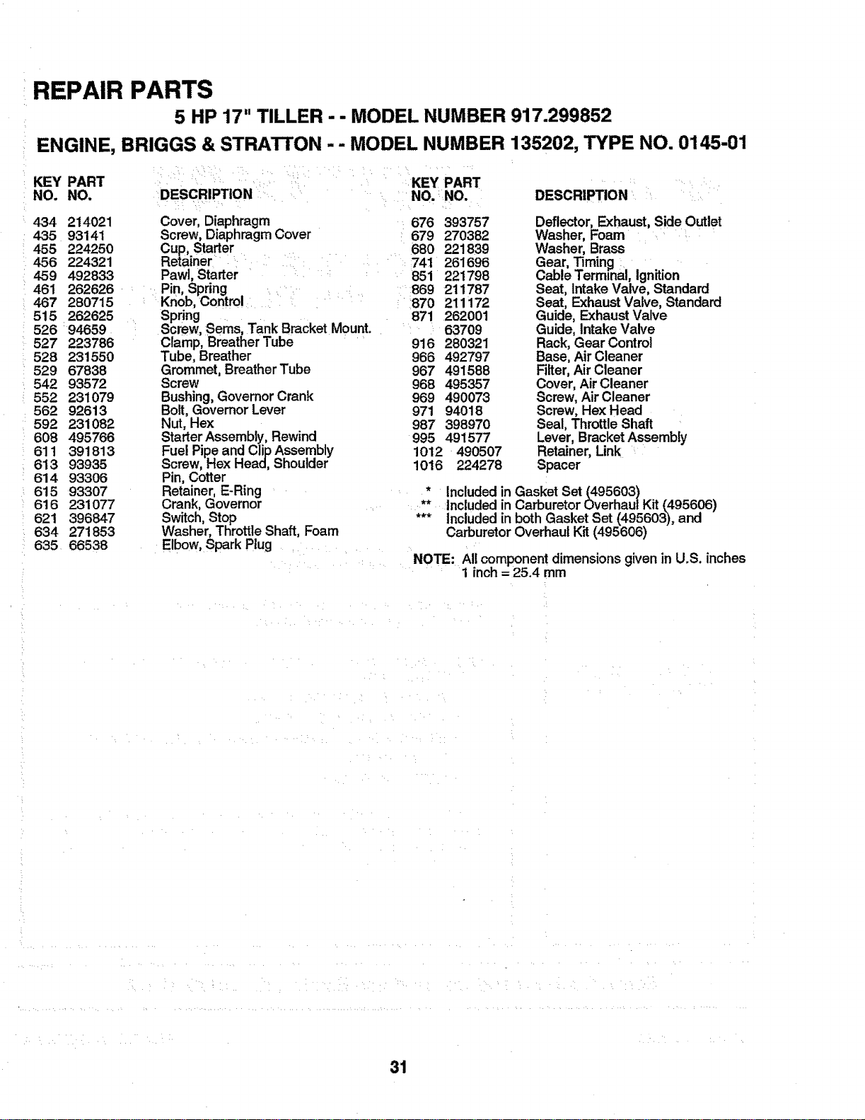
REPAIR PARTS
5 HP 17" TILLER - - MODEL NUMBER 917.299852
ENGINE, BRIGGS & STRATTON - - MODEL NUMBER 135202, TYPE NO. 0145-01
KEY PART
NO. NO,
434 214021
435 93141
455 224250
456 224321
459 492833
461 262626
467 280715
515 262625
526:94659
527 223786
528 231550
529 67838
542 93572
552 231079
562 92613
592 231082
608 495766
611 391813
613 93935
614 93306
615 93307
616 231077
621 396847
634 271853
635 66538
DESCRIPTION
Cover, Diaphragm
Screw, Diaphragm Cover
Cup, Starter
Retainer
Pawl, Starter
Pin, Spring .
Knob,Control i
Spring
Screw, Seres, Tank Bracket Mount.
Clamp, Breather Tube
Tube, Breather
Grommet, Breather Tube
Screw
Bushing,GovernorCrank
Bolt, GovernorLever
Nut, Hex
StarterAssembly, Rewind
Fuel Pipe and Clip Assembly
Screw, Hex Head, Shoulder
Pin, Cotter
Retainer, E-Ring
Crank, Governor
Switch, Stop
Washer, Throttle Shaft, Foam
Elbow, Spark Plug
::KEY PART ::
.... NO, :NO. DESCRIPTION
676
679
680
: 741
851
: :869
870
871
916
966
967
968
969
971
987
995
393757
270382
221839
261696
221798
211787
211172
262001
63709
280321
492797
491588
495357
490073
94018
398970
491577
1012 490507
1016 224278
Deflector, Exhaust, Side Outlet
Washer, Foam
Washer, Brass
Gear, Timing
Cable Terminal, Ignition
Seat, Intake Valve, Standard
Seat, ExhaustValve, Standard
Guide, Exhaust Valve
Guide, Intake Valve
Rack, Gear Control
Base, Air Cleaner
Filter, Air Cleaner
Cover, Air Cleaner
Screw, Air Cleaner
Screw, Hex Head
Seal, Throttle Shaft
Lever, Bracket Assembly
Retainer, Link
Spacer
* Included in Gasket Set (495603)
** Included in Carburetor Overhaul Kit (495606)
*** Included in both Gasket Set (495603), and
Carburetor Overhaul Kit (495606)
NOTE: All component dimensions given in U.S. inches
1 inch = 25.4 mm
31
OWNER'S
MANUAL
!
i i
MODEL NO,
917.299852
HOW TO ORDER
REPAIR PARTS
£RAFTSMA N°
5.0 HP
17 INCH TINE WIDTH
REAR TINE TILLER WITH
COUNTER ROTATING TINES
Each tiller has its own model number. Each engine has its own model
number,
The model number for your tillerwillbe found on a plate attached to the
top of the transmission.
The model number for your engine will be found on the blower housing of
the engine adjacent to the spark plug.
All parts listed hereinmay be ordered from any Sears, Roebuck, and Co.
Service Center and most Retail Stores.
WHEN ORDERING REPAIR PARTS, ALWAYS GIVE THE FOLLOW-
ING INFORMATION:
• PRODUCT - REAR TINE TILLER
° MODEL NUMBER - 917.299852
• ENGINE MODEL NUMBER - 135202, TYPE NUMBER 0145-01
° PART NUMBER
• PART DESCRIPTION
Your Sears merchandise has added value when you consider Sears has
service units nationwide staffed with Sears trained technicians.., profes-
sional technicians specifically trained to insure that we meet our pledge
to you, we service what we sell.
Sears, Roebuck and Co., Hoffman Estates, IL. 60179 U.S.A.
I II LIL I Zr LIII 12 U]IUlIIIIL III III Ill
137610 08.20.92 PRINTED tN THE U.S.A.