
590204D 04.13
US CA
INSTALLATION INSTRUCTIONS
DishDrawer
TM
dishwasher
DD24S 7 & DD24ST 7 models
2
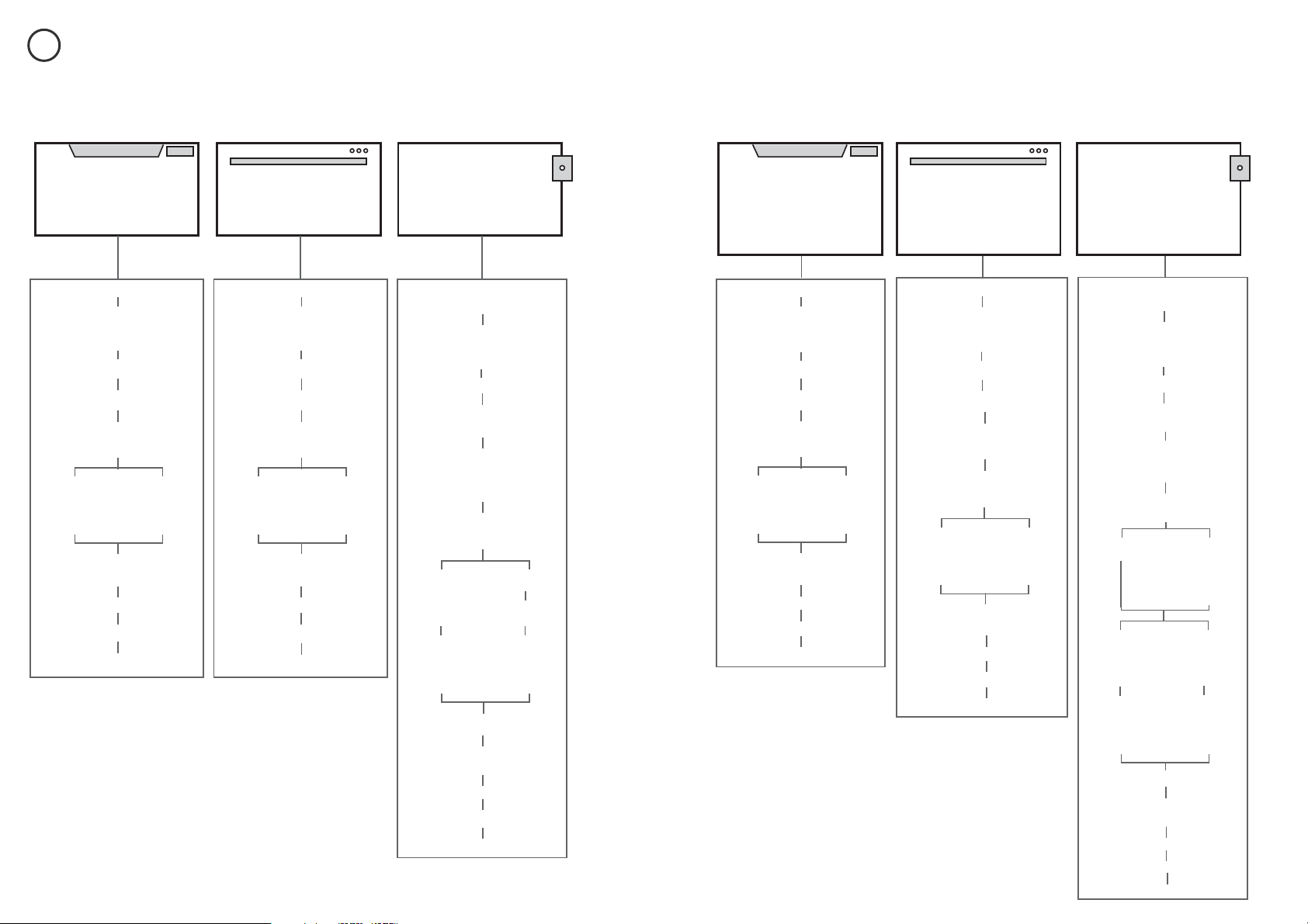
FOLLOW THE INSTALLATION SEQUENCE RELEVANT TO YOUR MODEL
1
Classic
PRODUCT & CABINETRY
DIMENSIONS
(STANDARD HEIGHT)
DD24SCX7
DD24SCW7
DD24SCB7
DD24SDFX7
Designer
DD24SI7
Integrated
CUSTOM FRONT
PANEL CALCULATIONS
PARTS SUPPLIED
OPTIONALLY HARD WIRING
PRODUCT & CABINETRY
DIMENSIONS
(STANDARD HEIGHT)
OPTIONALLY HARD WIRING
PRODUCT & CABINETRY
DIMENSIONS
(STANDARD HEIGHT)
OPTIONALLY HARD WIRING
CAVITY PREPARATION
MAXIMUM DISTANCE OF HOSES
& CORD FROM CHASSIS EDGE
SECURE WITHOUT
DRAWER REMOVAL
RECOMMENDED
METHOD (a)
ALTERNATIVE
METHOD (b)
SECURE BY
DRAWER REMOVAL
CHOOSE
DRAINAGE OPTION
CONNECT TO WATER & ELECTRICITY
FINAL CHECKLIST
TROUBLESHOOTING
CONNECT TO WATER & ELECTRICITY
CONNECT TO WATER & ELECTRICITY
PARTS SUPPLIED +
EXTERNAL VENTING KIT
PARTS SUPPLIED
CAVITY PREPARATION
MAXIMUM DISTANCE OF HOSES
& CORD FROM CHASSIS EDGE
SECURE WITHOUT
DRAWER REMOVAL
RECOMMENDED
METHOD (a)
ALTERNATIVE
METHOD (b)
SECURE BY
DRAWER REMOVAL
CHOOSE
DRAINAGE OPTION
FINAL CHECKLIST
TROUBLESHOOTING
INTEGRATED MODELS -
CAVITY PREPARATION &
EXTERNAL VENTING
MAXIMUM DISTANCE OF HOSES
& CORD FROM CHASSIS EDGE
FOLLOW STEPS
FOR THE
EXTERNAL
VENTING KIT
CHOOSE
DRAINAGE OPTION
INSTALL THE FRONT PANEL
FINAL CHECKLIST
TROUBLESHOOTING
FOLLOW STEPS
FOR THE
EXTERNAL
VENTING KIT
SECURE WITHOUT
DRAWER REMOVAL
RECOMMENDED
METHOD (a)
ALTERNATIVE
METHOD (b)
SECURE BY
DRAWER REMOVAL
DD24SCTX7
DD24SCHTX7
DD24SCTW7
DD24SCTB7
DD24SDFTX7
Integrated
Classic
Designer
DD24STI7
DD24SHTI7
CUSTOM FRONT
PANEL CALCULATIONS
CONNECT TO WATER & ELECTRICITY
CONNECT TO WATER & ELECTRICITY
CONNECT TO WATER & ELECTRICITY
PARTS SUPPLIED +
EXTERNAL VENTING KIT
CAVITY PREPARATION
AT TACH
CAVITY BRACKET
MAXIMUM DISTANCE OF HOSES
& CORD FROM CHASSIS EDGE
PRODUCT & CABINETRY
DIMENSIONS
(TALL HEIGHT)
PARTS SUPPLIED
OPTIONALLY HARD WIRING
PRODUCT & CABINETRY
DIMENSIONS
(TALL HEIGHT)
OPTIONALLY HARD WIRING
PRODUCT & CABINETRY
DIMENSIONS
(TALL HEIGHT)
OPTIONALLY HARD WIRING
CAVITY PREPARATION
MAXIMUM DISTANCE OF HOSES
& CORD FROM CHASSIS EDGE
SECURE WITHOUT
DRAWER REMOVAL
RECOMMENDED
METHOD (a)
ALTERNATIVE
METHOD (b)
SECURE BY
DRAWER REMOVAL
CHOOSE
DRAINAGE OPTION
FINAL CHECKLIST
TROUBLESHOOTING
CHOOSE
DRAINAGE OPTION
FINAL CHECKLIST
TROUBLESHOOTING
SECURE WITHOUT
DRAWER REMOVAL
RECOMMENDED
METHOD (a)
ALTERNATIVE
METHOD (b)
SECURE BY
DRAWER REMOVAL
PARTS SUPPLIED
INSTALL THE FRONT PANEL
18 ⁄" (480 mm)
CAVITY ONLY -
AT TACH
CAVITY BRACKET
CHOOSE
DRAINAGE OPTION
FINAL CHECKLIST
TROUBLESHOOTING
SECURE WITHOUT
DRAWER REMOVAL
RECOMMENDED
METHOD (a)
ALTERNATIVE
METHOD (b)
SECURE BY
DRAWER REMOVAL
FOLLOW STEPS
FOR THE
EXTERNAL
VENTING KIT
FOLLOW STEPS
FOR THE
EXTERNAL
VENTING KIT
INTEGRATED MODELS -
CAVITY PREPARATION &
EXTERNAL VENTING
MAXIMUM DISTANCE OF HOSES
& CORD FROM CHASSIS EDGE
18" (456 mm)
CAVITY
18 ⁄" (480 mm)
CAVITY
STANDARD HEIGHT SINGLE MODELS
TALL HEIGHT SINGLE MODELS
3
SAFETY AND WARNINGS - ALL MODELS
2a
ADDITIONAL SAFETY AND WARNINGS - INTEGRATED MODELS ONLY
2b
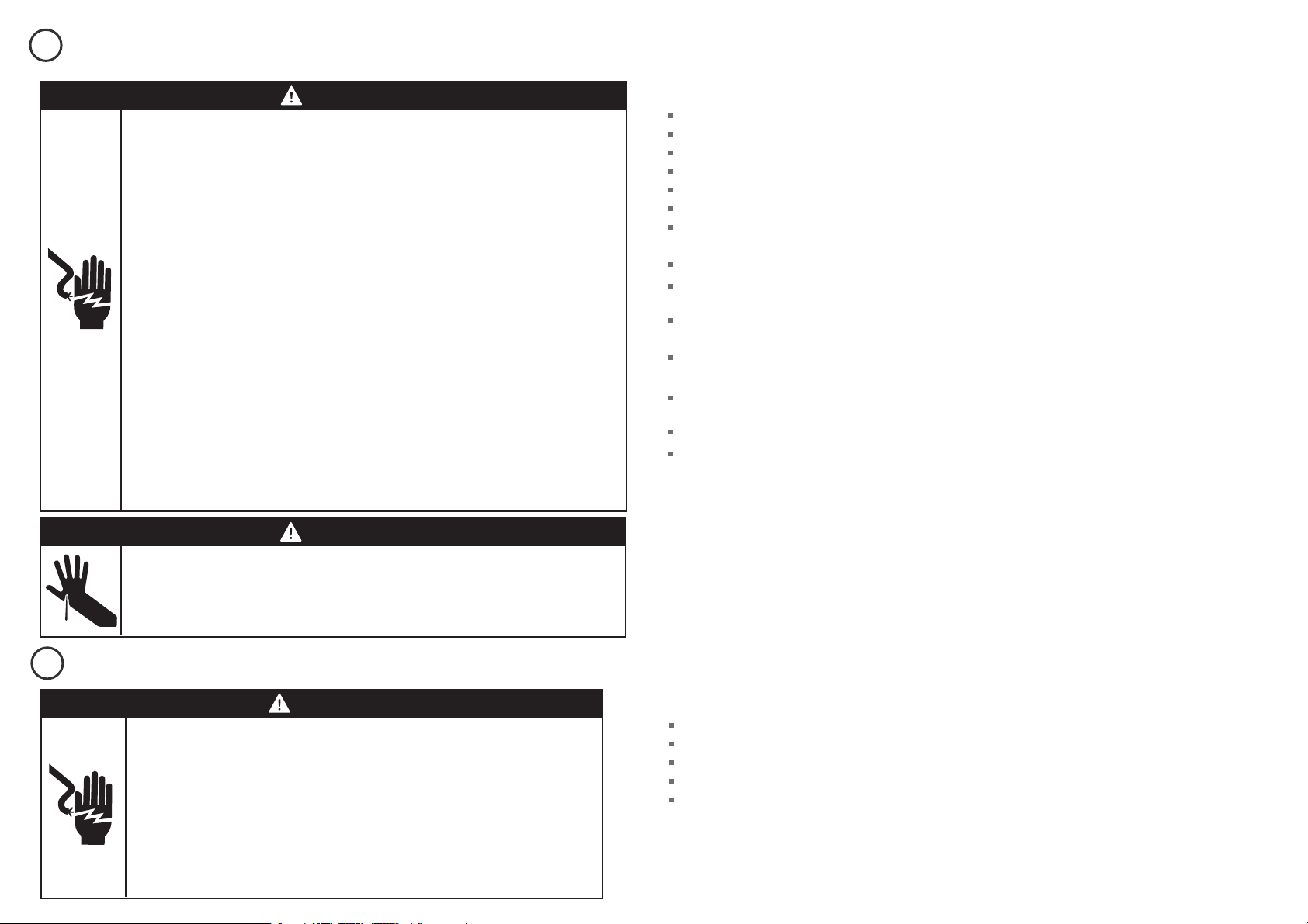
WARNING!
Electrical hazard
Before installing the dishwasher, remove the house fuse or open the circuit
breaker. If permanently connecting the dishwasher, be sure the power is isolated
and the dishwasher unplugged.
GROUNDING INSTRUCTIONS
This appliance must be grounded. In the event of a malfunction or breakdown,
grounding will reduce the risk of electric shock by providing a path of least
resistance for electric current. This appliance is equipped with a cord having
an equipment-grounding conductor and a grounding plug. The plug must be
plugged into an appropriate outlet that is installed and grounded in accordance
with all local codes and ordinances. WARNING - Improper connection of the
equipment-grounding conductor can result in a risk of electric shock. Check with
a qualified electrician or service representative if you are in doubt as to whether
the appliance is properly grounded.
If the dishwasher is installed as a permanently connected appliance:
GROUNDING INSTRUCTIONS - This appliance must be connected to a grounded
metal, permanent wiring system, or an equipment-grounding conductor must
be run with the circuit conductors and connected to the equipment-grounding
terminal or lead on the appliance.
Do not modify the power supply plug provided with the appliance - if it will not
fit the outlet, have a proper outlet installed by a qualified electrician. Do not use
an extension cord, adapter plug or multiple outlet box.
Failure to follow this advice may result in electrical shock or death.
WARNING!
Cut hazard
Take care - panel edges are sharp.
Failure to use caution could result in injury or cuts.
IMPORTANT SAFETY INSTRUCTIONS!
Installation of this dishwasher requires basic mechanical and electrical skills.
Be sure to leave these Instructions with the Customer.
Installation must comply with your local building, electricity, and plumbing regulations.
At the completion of the dishwasher installation, the Installer must perform the Final Checklist.
Remove all packaging materials supplied with the dishwasher.
This dishwasher is manufactured for indoor use only.
Ensure all water connections are turned OFF. It is the responsibility of the plumber and
electrician to ensure that each installation complies with all Codes and Regulations.
The dishwasher MUST be installed to allow for future removal from the enclosure if service is required.
The switched power outlet must be outside the dishwasher cavity, so that it is accessible after
installation.
Care should be taken when the appliance is installed or removed to reduce the likelihood of damage to
the power supply cord and hoses.
If the dishwasher is to be relocated from one installation to another it must be kept upright to avoid
damage from water spillage.
Make sure only new hoses are used for connection (supplied with the dishwasher). Old hoses should
not be reused.
Failure to install the dishwasher correctly could invalidate any warranty or liability claims.
If the product is installed in a motor vehicle, boat or similar mobile facility, you must bring the vehicle,
boat or mobile facility containing the product to the service shop at your expense or pay the service
technician’s travel to the location of the product.
SAVE THESE INSTRUCTIONS
IMPORTANT SAFETY INSTRUCTIONS!
Read these instructions completely and carefully.
Ensure the product is not plugged in.
Installation of custom panels requires basic mechanical and electrical skills.
Installation must comply with your local building and electricity regulations.
Failure to install the custom panels correctly could invalidate any warranty or liability claims.
SAVE THESE INSTRUCTIONS
WARNING!
Electrical Shock Hazard
WARNING: To reduce the risk of electrical shock, fire, or injury to persons, the
installer must ensure that the dishwasher is completely enclosed at the time
of installation.
Before fitting the front panel, make sure that the dishwasher is disconnected
from the power supply. After installing the front panel, the installer must
ensure that the following components are electrically grounded: the panel
bracket and any custom metal component (e.g. handle) that extends past the
rubber seal.
Failure to follow these warnings may result in electrical shock, injury or fire.
4
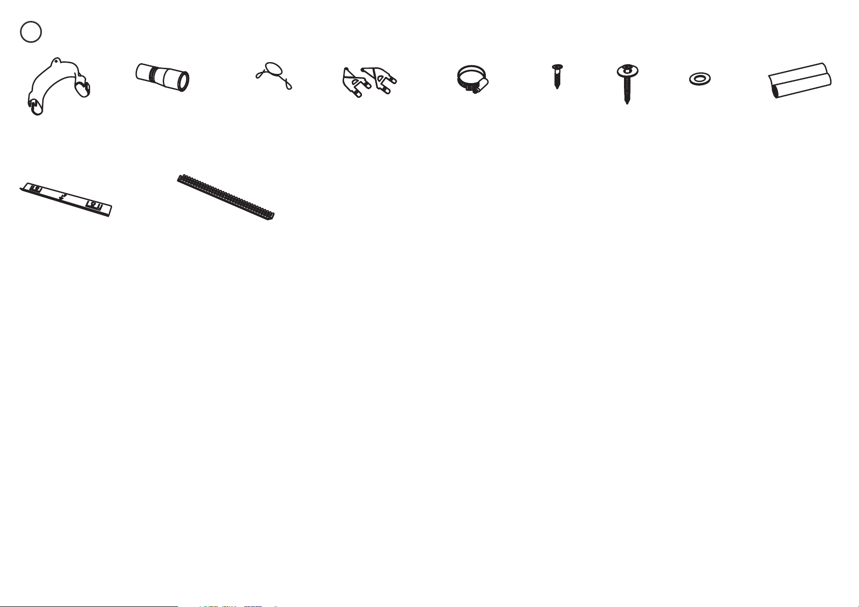
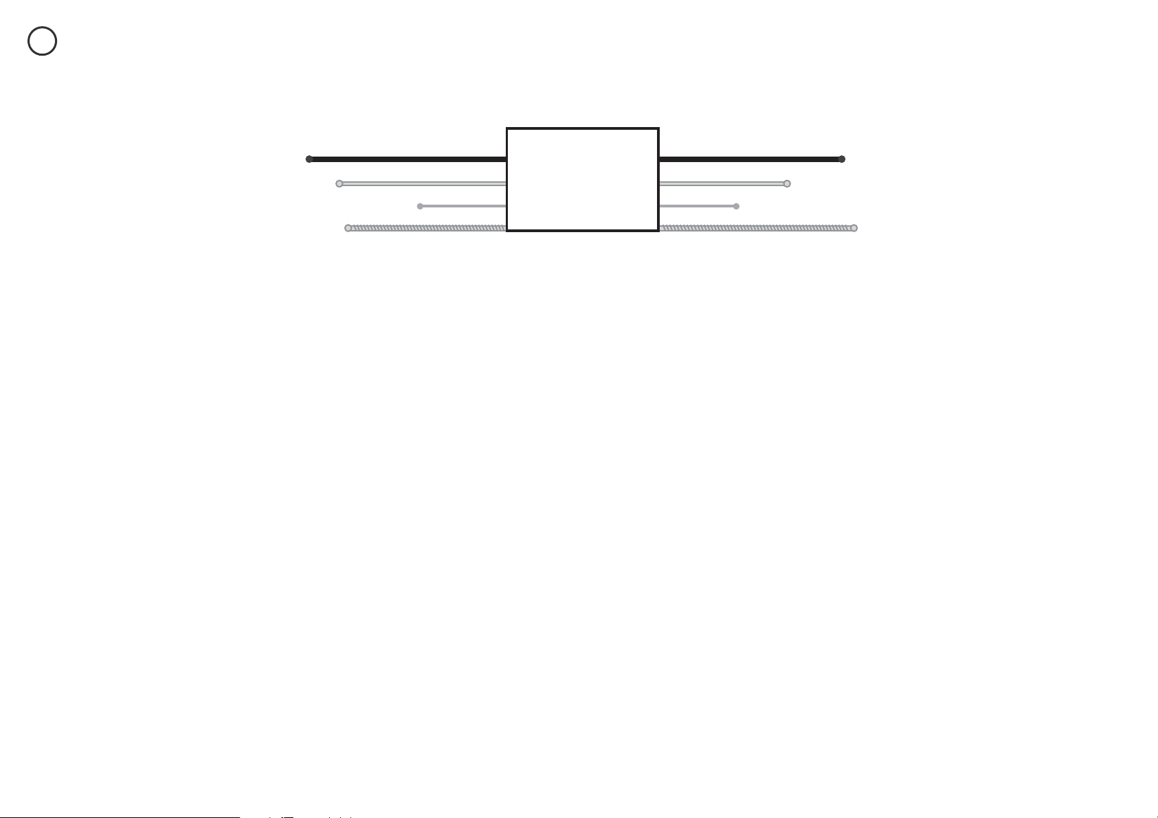
PARTS SUPPLIED - ALL MODELS
3a
Phillips
⁄” (16 mm)
screws (7)
1½ ” (38 mm)
bottom fixing
screws & metal
washers (2)
Drain hose
support (1)
Cavity bracket kit (1)
supplied with Tall height
Designer and
Integrated models only
Drain hose
joiner (1)
Side mounting
bracket kit
(A and B) (2)
OPTIONAL
If the Drain hose supplied is not long enough to reach your services, you must use a Drain Hose Extension Kit P/N 525798 which will extend the drain hoses by 11’ 10” (3.6m).
The kit is available from the nearest Fisher & Paykel Authorized Service Center, or Toll free 1.888.936.7872 or www.fisherpaykel.com
Edge Protector (1)
(If the services hole is through
a metal partition the hole
must be protected with the
Edge protector supplied to
prevent damage to the power
cord or hoses.)
Wire clip (1)
(for securing
Drain hose joiner)
Moisture protection
tape (1)
(to prevent moisture
damage)
Clamp (1)
(for securing
Drain hose joiner)
Rubber
washer for
inlet hose (1)
(comes already
fitted)
5
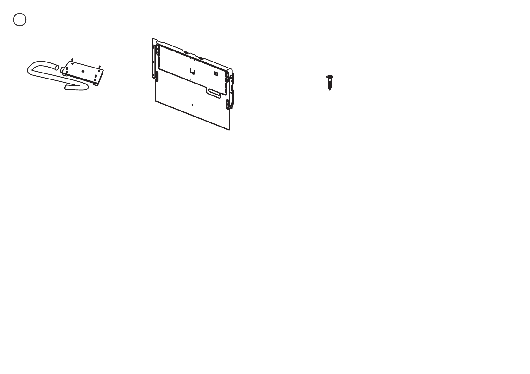
ADDITIONAL PARTS SUPPLIED WITH INTEGRATED MODELS
3b
External Venting kit (1) Panel mounting
screws (6)
Panel bracket (1)
(attached to product)
6
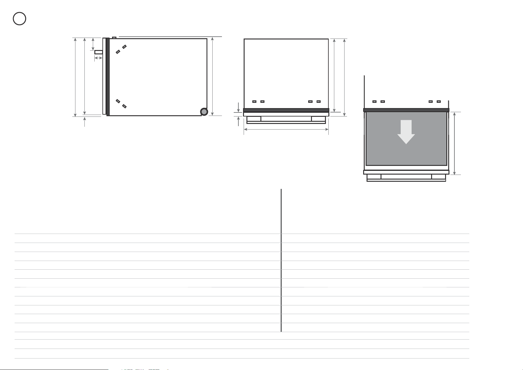
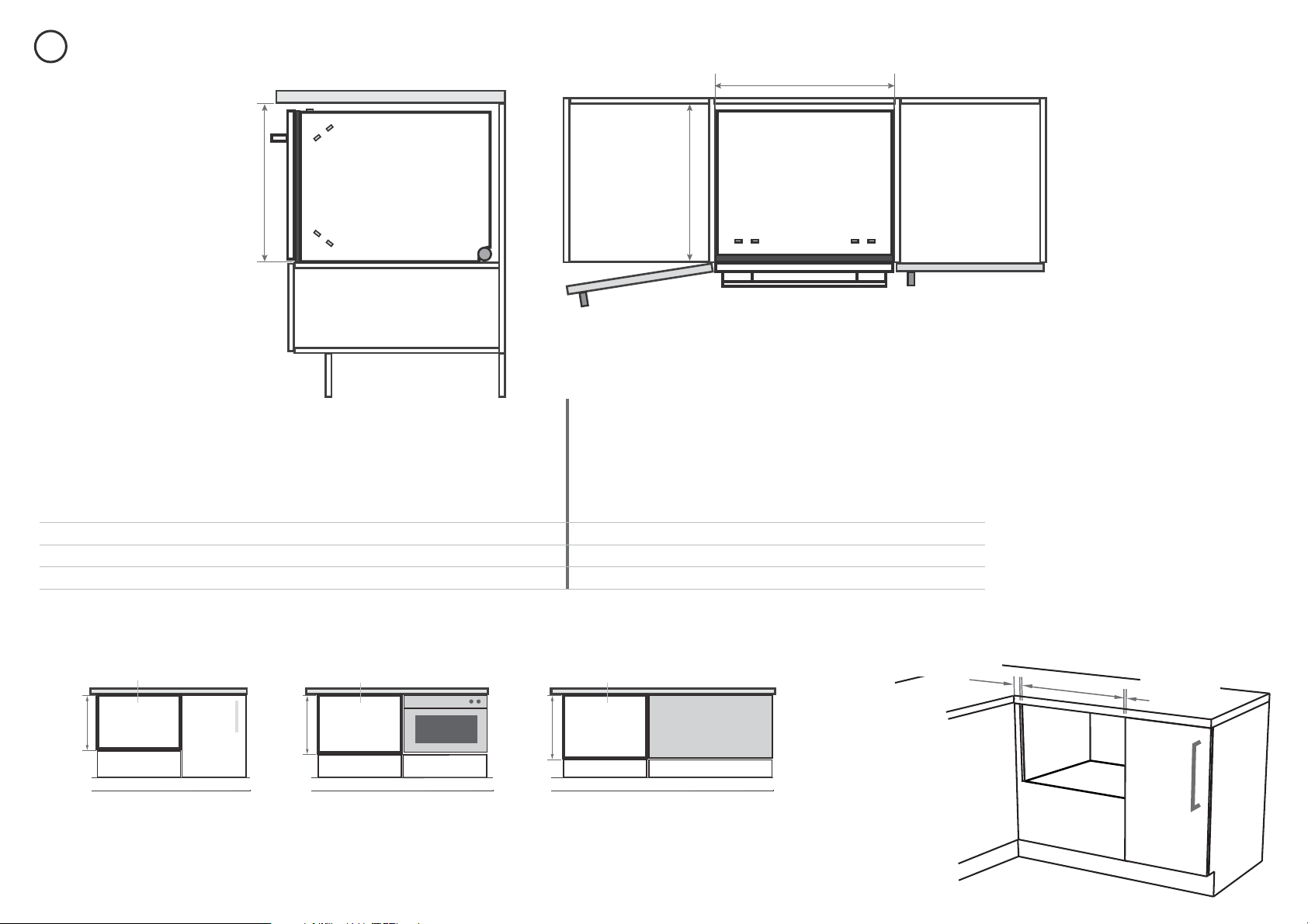
4
PRODUCT DIMENSIONS
A
H
I
J
K
Side
Plan
G
F
B
CD
E
Product dimensions inches (mm)
STANDARD HEIGHT MODELS TALL HEIGHT MODELS
Classic
Designer
Integrated
Classic
Designer
Integrated
18”
(456 mm)
cavity
Integrated
18 ⁄”
(480 mm)
cavity
A
overall height
1
of product (incl. front panel height) 16 ⁄”(410) 16 ⁄”(410) 16 ⁄”(410) 17 ⁄”(454) 18 ⁄”(478)
2
17 ⁄”(454) 18 ⁄”(478)
2
B
overall width of product 23 ⁄”(599) 23 ⁄”(599) 23 ⁄”(599) 23 ⁄”(599) 23 ⁄”(599) 23 ⁄”(599) 23 ⁄”(599)
C
overall depth of product (excl. handle) 22 ⁄”(582) 22 ½ ”(571) 22 ½ ”(571)
3
22 ⁄”(582) 22 ½ ”(571) 22 ½ ”(571)
3
22 ½ ”(571)
3
D
depth of chassis (to back of front panel) 21 ¾ ”(553) 21 ¾ ”(553) 21 ¾ ”(553) 21 ¾ ”(553) 21 ¾ ”(553) 21 ¾ ”(553) 21 ¾ ”(553)
E
maximum extension of drawer (excl. handle) 21 ⁄”(556) 21 ⁄”(545) 21 ⁄”(545)
3
21 ⁄”(556) 21 ⁄”(545) 21 ⁄”(545)
3
21 ⁄”(545)
3
F
depth of front panel (excl. handle) 1 ⁄”(29) ⁄”(18) ⁄- ⁄”(16-20) 1 ⁄”(29) ⁄”(18) ⁄- ⁄”(16-20) ⁄- ⁄”(16-20)
G
height
1
of chassis 16 ⁄”(410) 16 ⁄”(410) 16 ⁄”(410) 17 ⁄”(454) 17 ⁄”(454) 17 ⁄”(454) 17 ⁄”(454)
H
depth of handle n/a 1 ⁄”(41) n/a n/a 1 ⁄”(41) n/a n/a
I
height of front panel 15 ½ ”(394) 15 ⁄”(398) 16 ⁄”(408)
4
17 ¼ ”(438) 18 ½ ”(470) 17 ⁄”(452)
5
18 ¾ ”(476)
5
J
height of ventilation gap below front panel ¼ ”(7) ⁄”(8) min. ⁄”(2)¼ ”(7) ⁄”(8) min. ⁄”(2) min. ⁄”(2)
K
height from top of handle to top of front panel n/a 2 ½ ”(64) n/a n/a 2 ½ ”(64) n/a n/a
1
includes ⁄” (2 mm) high bracket slots
2
Includes cavity bracket
3
Assuming front panel thickness of ⁄” (18 mm)
4
Recommended for a ⁄” (2 mm) ventilation gap below panel, if cavity height is 16 ¼ ” (412 mm)
5
Recommended for a ⁄” (2 mm) ventilation gap below panel
7
5
CABINETRY DIMENSIONS
Plan
Side
L
N
M
Minimum clearances from adjacent cabinetry
Cabinetry dimensions inches (mm)
STANDARD HEIGHT MODELS TALL HEIGHT MODELS
Classic
Designer
Integrated
Classic
Designer
Integrated
18”
(456 mm)
cavity
Integrated
18 ⁄”
(480 mm)
cavity
L
inside height of cavity min. 16 ¼ ”(412) min. 16 ¼ ”(412) min. 16 ¼ ”(412) 18”(456) 18 ⁄”(480) 18”(456) 18 ⁄”(480)
M
inside width of cavity 23 ⁄”(600) 23 ⁄”(600) 23 ⁄”(600) 23 ⁄”(600) 23 ⁄”(600) 23 ⁄”(600) 23 ⁄”(600)
N
inside depth of cavity min. 22 ⁄”(560) min. 22 ⁄”(560) min. 22 ⁄”(560) min. 22 ⁄”(560) min. 22 ⁄”(560) min. 22 ⁄”(560) min. 22 ⁄”(560)
min. ½ ” (13 mm)
clearance from a
corner cupboard
min. ⁄” (2 mm)
clearance
to adjacent
cupboard door
min.
16 ¼ ”
(412 mm)
18 ⁄”
(480 mm)
18 ”
(456 mm)
L
LL
Dishwasher Dishwasher Dishwasher
Standard height models
Tall height Classic models
Tall height Integrated models
Oven
CoolDrawer
Tall height Designer models
Cavity height options allow you to match dishwasher with your cabinetry or companion products
You may choose to install Tall height Integrated
models into either a 18” (456 mm) or a
18 ⁄” (480 mm) high cavity.
Note: the minimum height of the custom drawer front
panel will also be different for these two options.
8
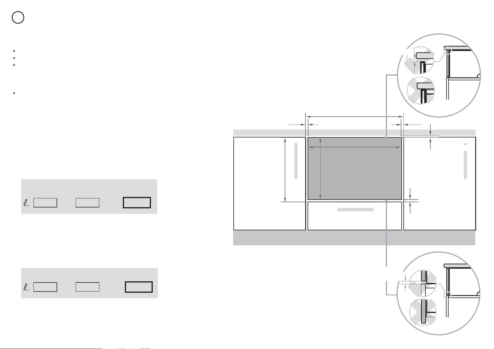
The following calculations assume the top of the panel is aligned
with the top of the adjacent cabinetry:
WIDTH OF THE PANEL
Measure
A (
the width between adjacent door/drawer fronts)
and write it in the rst box below, then complete the equation.
HEIGHT OF THE PANEL
Measure
B
and write it in the rst box below, then complete
the equation.
min. ⁄” (2mm) ventilation
gap with external venting
kit installed
min. ⁄” (2mm) ventilation gap with
external venting kit installed
WIDTH OF PANEL
HEIGHT
OF PANEL
A
B
A
B
clearance to
adjacent cabinet
front
(min. ⁄” (2 mm))
ventilation gap
(min. ⁄” (2 mm))
HEIGHT OF PANEL
- 2x
-
=
=
FRONT PANEL SPECIFICATIONS
⁄- ⁄” (16-20 mm) panel thickness
Maximum weight of panel: 20 lb (9 kg)
Adequately sealed to withstand moisture (122
O
F/ 50
O
C @ 80% RH).
Because of it being a hot and wet environment generally, the back
and sides of the panel should be completely sealed with a waterproof
vapour barrier (ie polyurethane) to prevent damage to the panel.
The back of the panel (including any integrated handle) should be
completely flush so that the seal between the panel and the rubber
trim is maintained.
INTEGRATED MODELS ONLY - CUSTOM FRONT PANEL CALCULATIONS
6
Note: when the top of the dishwasher has to be lower than the adjacent cabinetry,
the panel can be increased in height.
min. ⁄”(2mm) min. ⁄”(2mm)
min. ⁄”(2mm)
min. ⁄”(2mm)
WIDTH OF PANEL
(min. 23 ⁄” (596 mm))
9
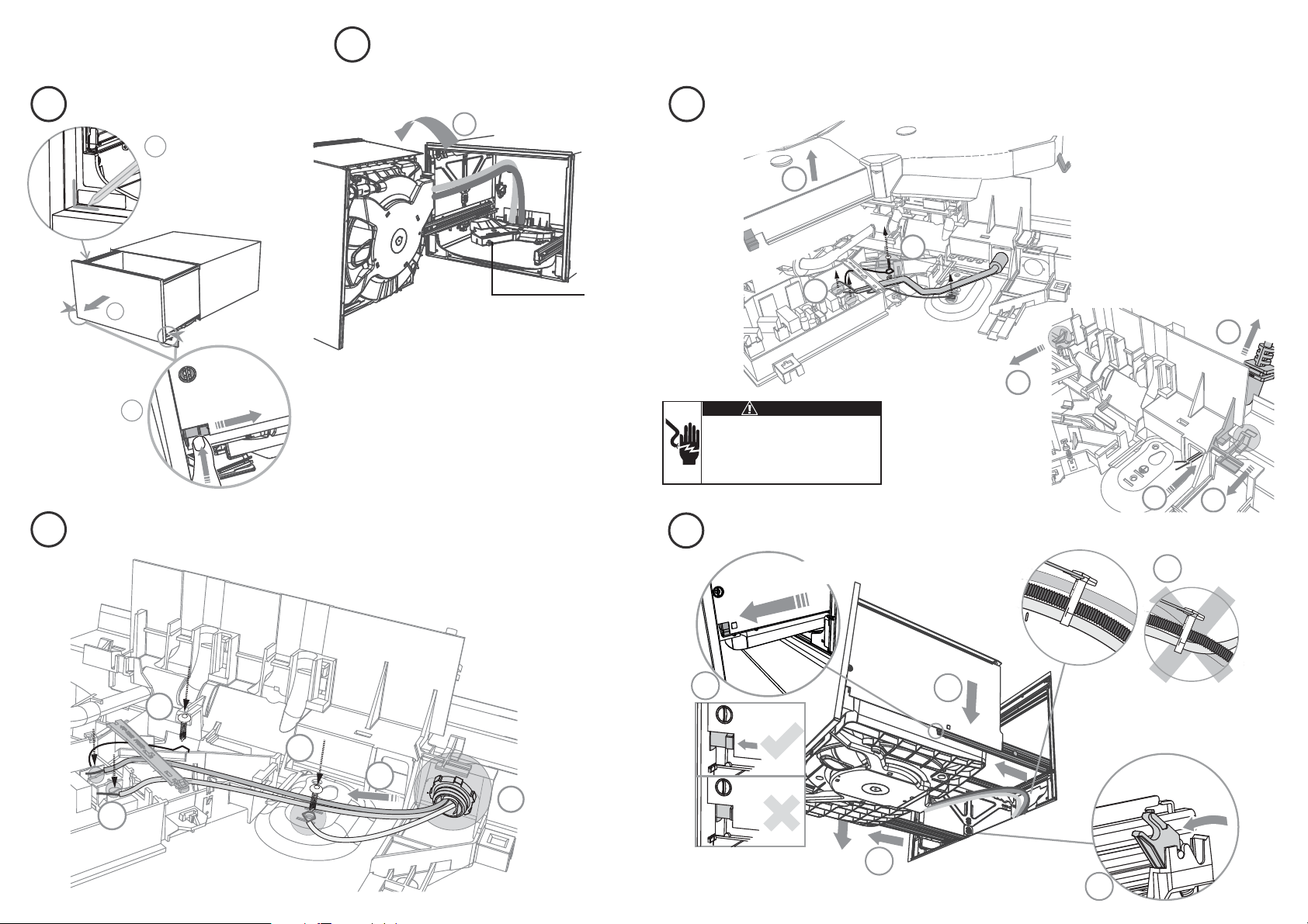
OPTIONALLY HARD WIRING PRIOR TO INSTALLATION
9
12
11
11
10
4
5
6
7
7
8
8
7a
7c
7
7b
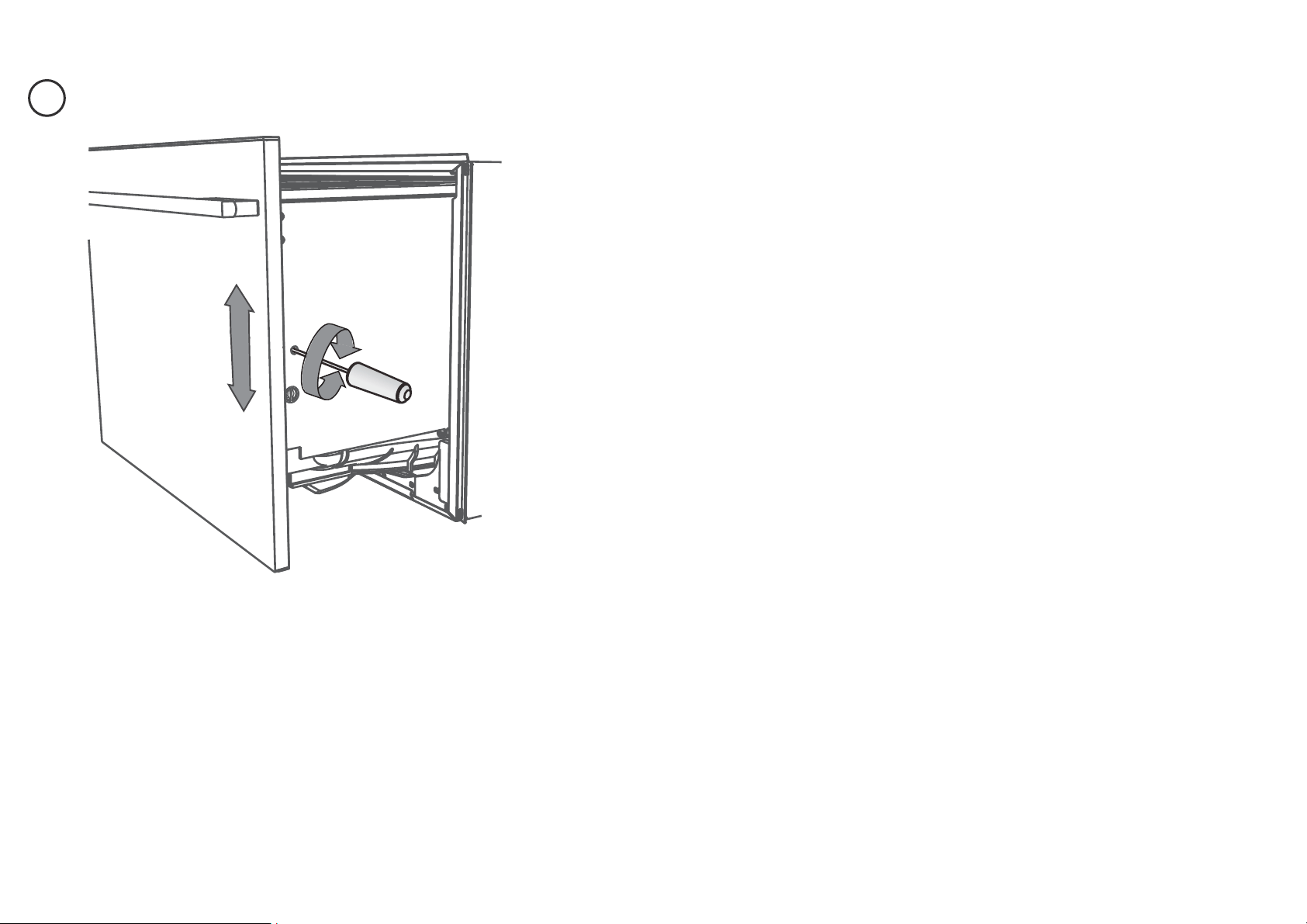
REMOVE THE DRAWER
TERMINATE THE WIRING AS SHOWN
REMOVE THE ACCESS COVER & POWER CORD
Remove knock-out for cable clamp and
fit a suitable cable clamp for the conduit.
Use copper conductors only.
2
100 mm
1
3
4
5
To prevent kinked hoses, we recommend
rotating the drawer counter-clockwise
and resting it on its side after removal.
Product may move.
Mark chassis position
on cavity
Access
cover
Press the release tabs in on
either side and push back
to release drawer from
runners.
3
4” (100mm)
18
19
15
16
17
Before refitting the drawer,
ensure the hoses are not
twisted and the latches at
the rear of each drawer
runner are facing forward.
Ensure the release tabs on
both sides are reset fully.
Ensure the drawer
is now rotated
clockwise back.
13
14
15
16
17
Pull forward the release tabs
on both sides 4”(100
mm)
7d
REFIT THE DRAWER ONTO THE RUNNERS & CLOSE
Electrical Shock Hazard
Before continuing, ensure that the product is
disconnected from the power supply.
Failure to follow this warning may result in
electrical shock, injury or re.
WARNING!
10
8
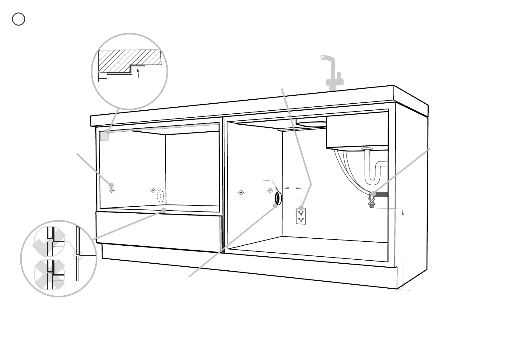
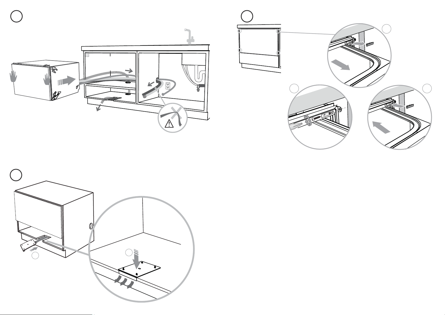
CAVITY PREPARATION
Important!
Adjacent cabinetry
must not extend
above cavity base
Moisture
protection
tape must
be applied.
Services can be
located either side
of the dishwasher.
These marks indicate
formed bracket screw
locations, if securing
by drawer removal.
If there is no side
partition, you can
construct timber
bracing as something
to secure into.
COUNTERTOP
Water Connection
Recommended HOT
(Maximum 140°F/60°C).
Supplied hose to
suit ⁄” (9 mm) male
compression fitting.
Water Pressure
Water softener models
Max. 1 MPa (145 psi)
Min. 0.1 MPa (14.5 psi)
Models without
water softener
Max. 1 MPa (145 psi)
Min. 0.03 MPa (4.3 psi)
Important!
The power outlet must be
located in a cabinet adjacent
to the dishwasher cavity.
110-120 VAC max. 15 A
min. 7 ⁄” (200 mm)
⁄” (10mm)
max. 17 ⁄”
(450 mm)
ø
max. 1½ ” (38 mm)
Services hole
Can be located either side of dishwasher, preferably
at the bottom of the cavity, as shown. If adequate
clearance, services hole can be made higher to clear
toekick space. If hole is higher, ensure drain hose(s)
are routed straight into the waste connection.
- If the hole is through wood, make sure its edges
are smooth and rounded.
- If the hole is through metal, ensure you t the
supplied Edge Protector to prevent damage to the
power cord.
11
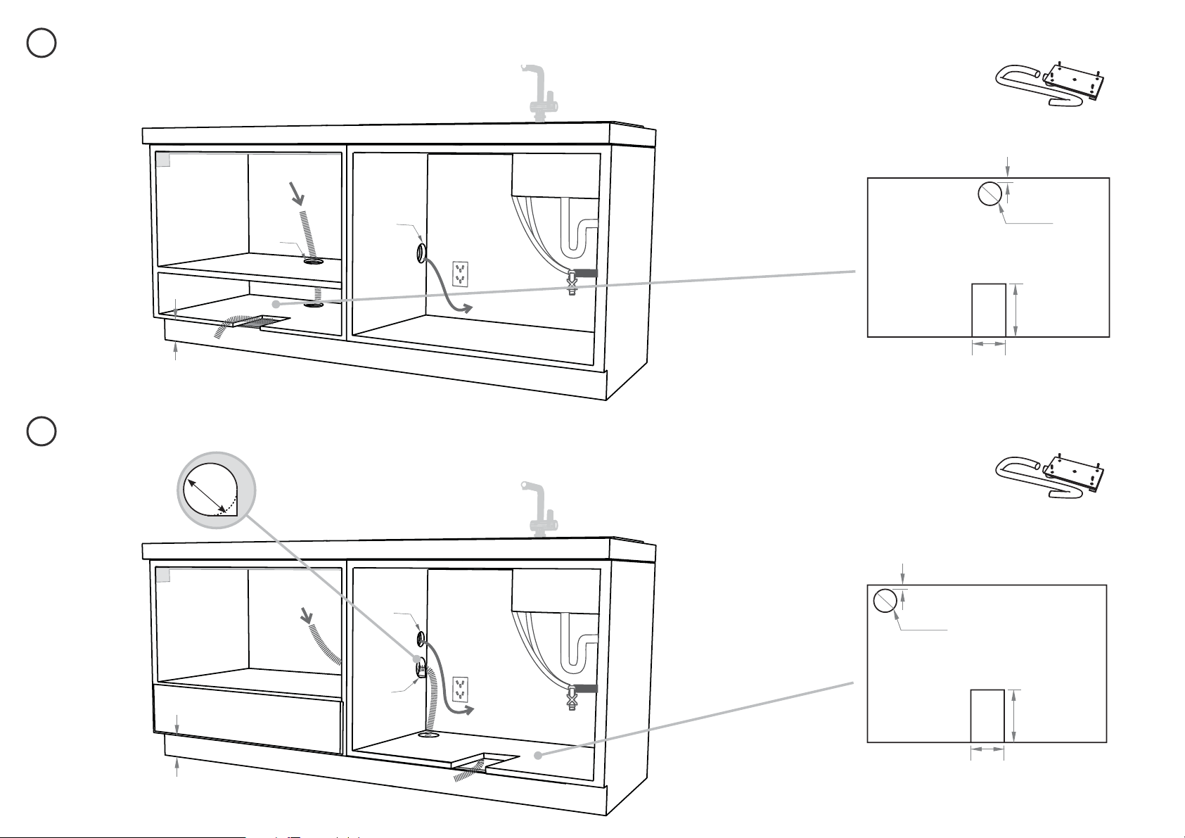
9a
9b
INTEGRATED MODELS ONLY - PREPARATION FOR EXTERNAL VENTING THROUGH SAME CABINET
INTEGRATED MODELS ONLY - PREPARATION FOR EXTERNAL VENTING THROUGH ADJACENT CABINET
ø
2 ⁄” (60 mm)
ø
2 ⁄” (60 mm)
max. ⁄” (
5 mm)
max. ⁄” (
5 mm)
8 ⁄” (220 mm)
8 ⁄” (220 mm)
4” (100 mm)
4” (100 mm)
ø 2 ⁄”
60mm
Services can be located
either side of dishwasher
VENT HOSE
VENT HOSE
+ DRAIN HOSE
+ INLET HOSE
POWER CORD
DRAIN HOSE + INLET
HOSE + POWER CORD
Services can be located
either side of dishwasher
Shelf cutouts
Shelf cutouts
The ø 2 ⁄” (60 mm) services hole
for the hoses should be enlarged
to accomodate the extra venting
hose by cutting out some material
from the bottom corner.
If the services holes
are through metal,
ensure you t the
supplied Edge
Protector around the
hole for the power
cord.
External Venting kit (1)
External Venting kit (1)
ø
2 ⁄” (60 mm)
ø
2 ⁄”
(60 mm)
ø
max. 1½ ” (38 mm)
ø
max. 1½ ”
(38 mm)
min.4” (100 mm)
min.4” (100 mm)
Important!
To prevent pooling of condensation from the vent hose, a
toekick height of no less than 4” (100 mm) is required.
Important!
To prevent pooling of condensation from the vent hose, a
toekick height of no less than 4” (100 mm) is required.
12
10
MAXIMUM DISTANCE OF HOSES & CORD FROM CHASSIS EDGE
Left hand side Right hand side
Drain hose - 78 ½" (2000 mm)
Inlet hose - 64 ¾" (1650 mm)
Venting hose - 60 ⁄" (1525 mm) Venting hose - 75 ⁄" (1925 mm)
(Integrated models only) (Integrated models only)
Power cord
(excl. plug)
- 29 ½" (750 mm) Power cord
(excl. plug)
- 27 ½" (700 mm)
Drain hose - 70 ½" (1800 mm)
Inlet hose - 49" (1250 mm)
13
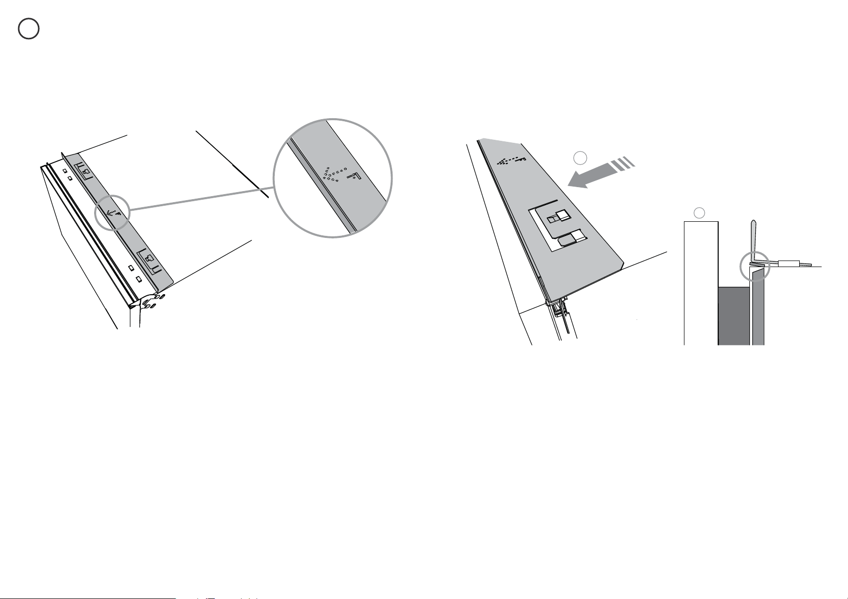
DESIGNER & INTEGRATED TALL MODELS FOR 18 ⁄” (480 mm) CAVITY ONLY - ATTACH CAVITY BRACKET
11
The enclosed cavity bracket is tted before installation in order to conceal the gap at the top of the cavity left after installation.
2
1
Ensure the cavity panel
bracket is positioned so
that the “F” arrow is
pointing towards the front
of the chassis.
Firmly push the bracket so that
the prongs engage with the top
tabs and it clicks into place.
Ensure the top trim seal
is facing forward after
attaching the bracket.
Important!
Ensure the prongs have not been
driven down into the chassis as
this will damage the lid below.
12
14
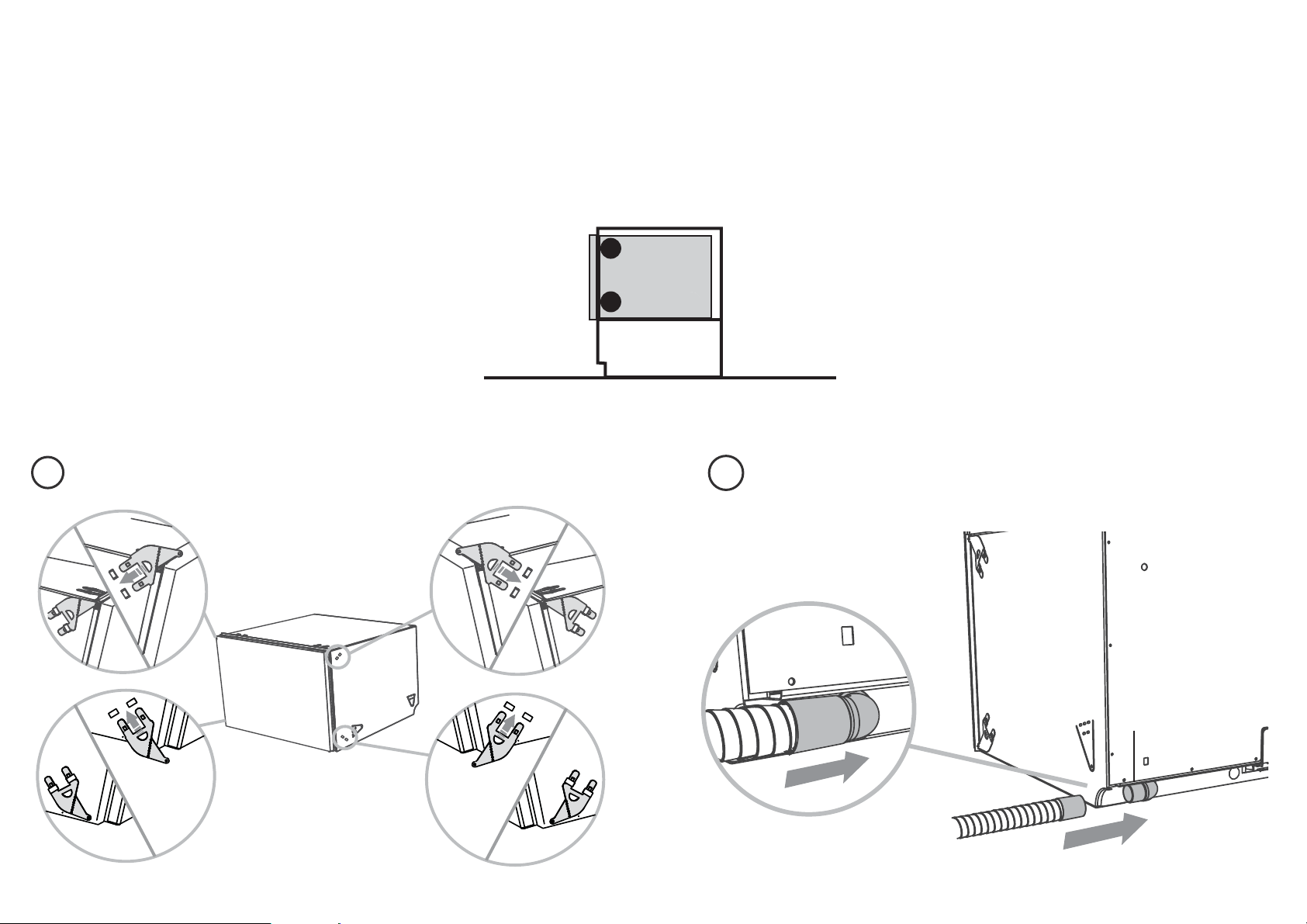
RECOMMENDED METHOD (a) - SECURE WITHOUT DRAWER REMOVAL (FRAMELESS CABINETRY ONLY)
13a12a
ATTACH SIDE MOUNTING BRACKETS
INTEGRATED ONLY - ATTACH VENTING HOSE
Fitted Elbow
Clip all four side mounting
brackets into their slots
using a flat-bladed
screwdriver. Ensure they’re
securely fitted before
sliding product into cavity.
The mounting slots are in pairs,
one on each side diagonally
across the product. A bracket
must match A slot and B
bracket must match B slot.
Check that the fitted elbow is rotated
left or right (depending on the direction
of the routing), then ensure the venting
hose is securely attached to it.
NOW CHOOSE WHICH INSTALLATION METHOD (a) or (b)
IS MORE SUITABLE FOR YOUR CABINETRY...
A
A
B
B
B
B
A
A
15
14a 15a
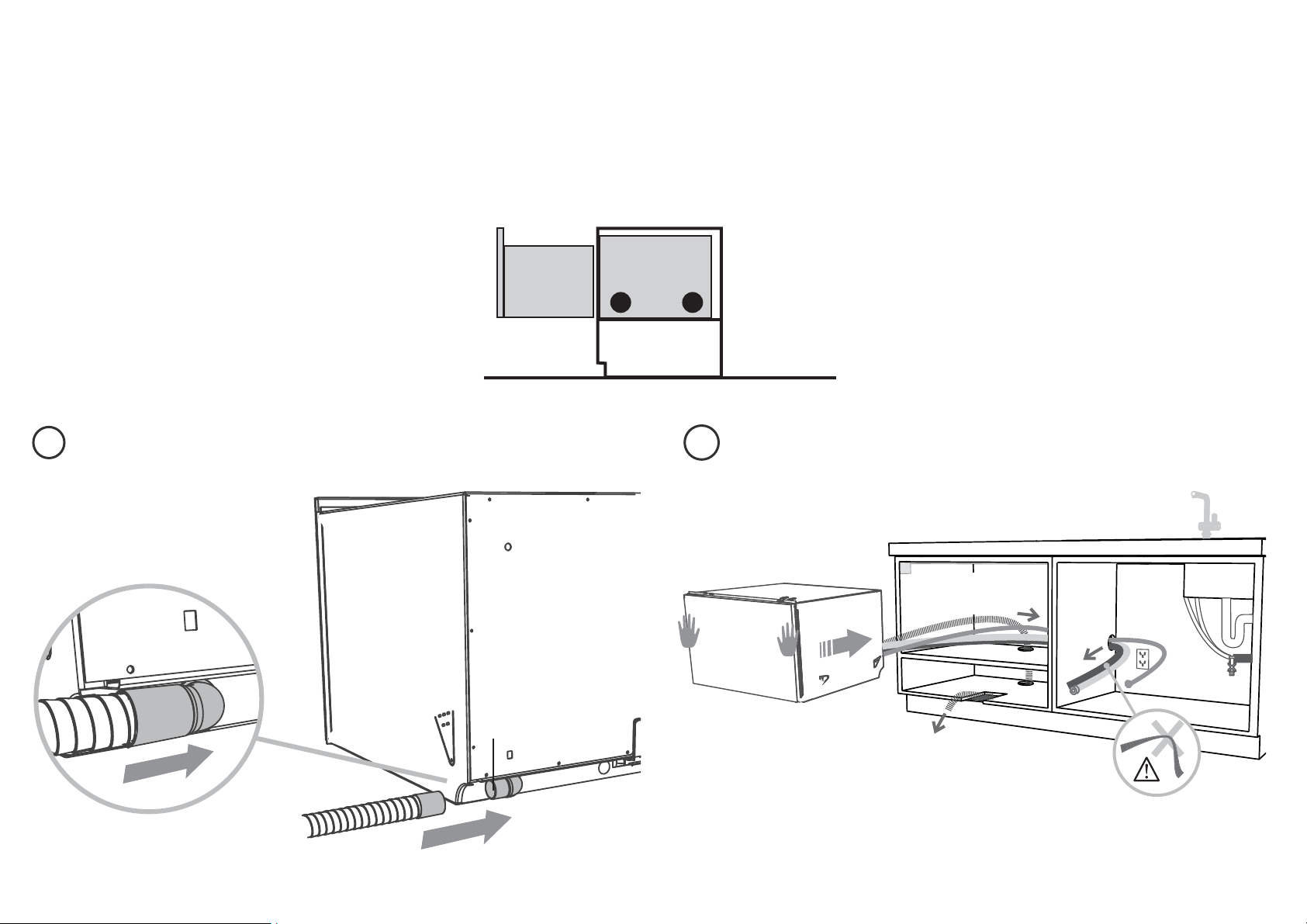
PULL THROUGH HOSES & MOVE INTO THE CAVITY SECURE THE DRAWER
As you push product in, pull through hoses and
cord, ensuring they don’t get kinked or twisted.
Important!
If product cannot be pushed in far enough, pull
out again and rearrange hoses and cord. Do not
use excessive force, as doing so may squash the
hoses and lead to incorrect operation.
Vent Hose
(Integrated
models only)
vent either
through
same cabinet
or adjacent
cabinet as per
step 9a or 9b
1
32
Open the
drawer halfway.
Using a flat-bladed
screwdriver, prize
the gray
rubber plug out
of the trim moulding.
Replace the gray
rubber plug back into
the trim moulding
and ensure the trim
seal is facing forward.
Repeat for all
four brackets.
Using a small Philips
screwdriver,
screw through the trim
moulding, securing the
side mounting bracket
to the cabinetry.
Do not damage the
rubber trimseal.
16a
INTEGRATED ONLY - SECURE THE EXTERNAL VENT
2
1
After routing the vent hose
through and out the hole
cutout, attach and secure the
vent by tightening the four
screws provided.
Airflow
16
13b12b
INTEGRATED ONLY - ATTACH VENTING HOSE PULL THROUGH HOSES & MOVE INTO THE CAVITY
Fitted Elbow
Check that the fitted elbow is
rotated left or right (depending
on the direction of the routing),
then ensure the venting hose is
securely attached to it.
Vent Hose
(Integrated
models only)
vent either
through
same cabinet
or adjacent
cabinet as per
step 9a or 9b
ALTERNATIVE METHOD (b) - SECURE BY DRAWER REMOVAL
As you push product in, pull through hoses and
cord, ensuring they don’t get kinked or twisted.
Important!
If product cannot be pushed in far enough, pull
out again and rearrange hoses and cord. Do not
use excessive force, as doing so may squash the
hoses and lead to incorrect operation.
17
14b
16b
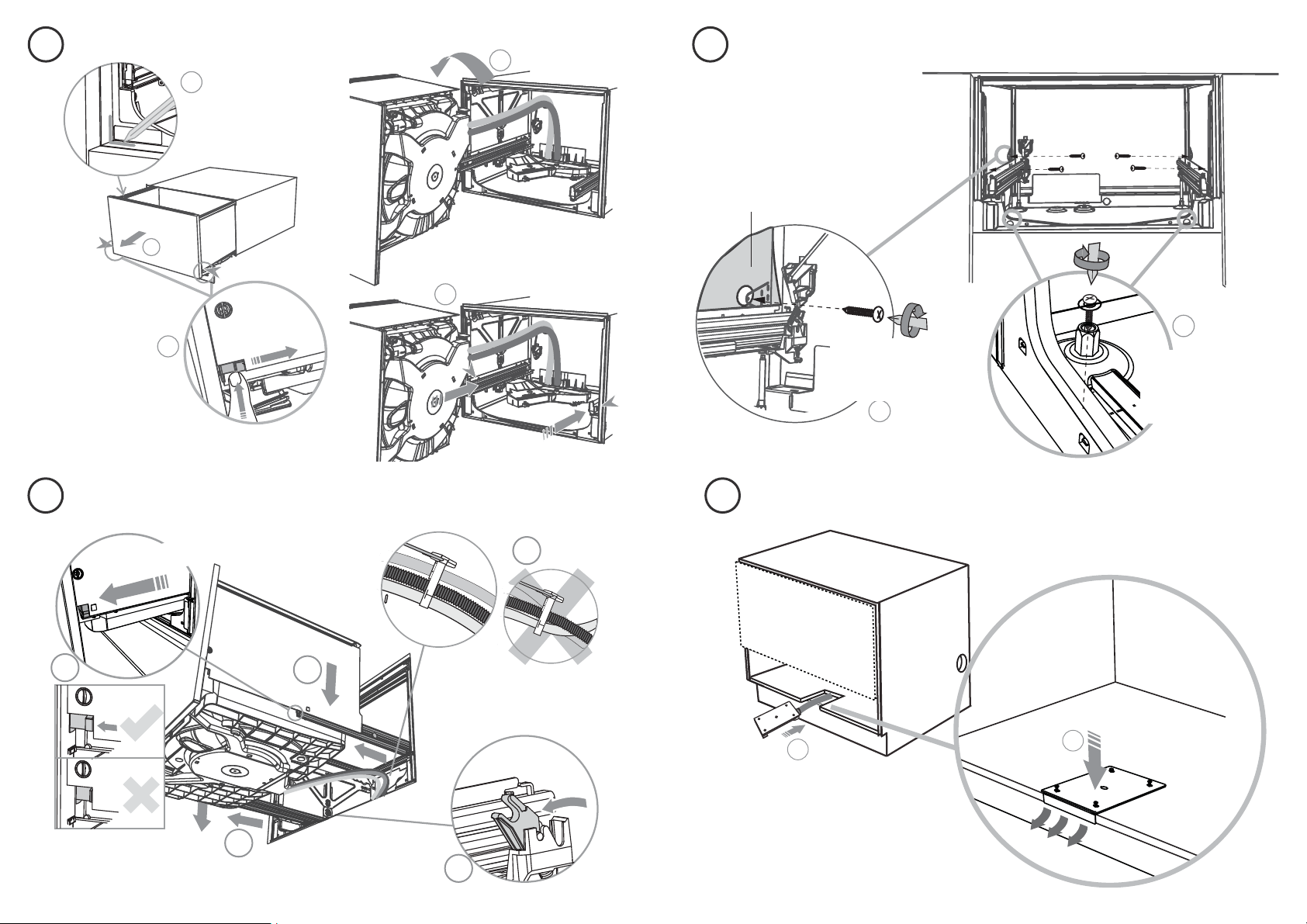
REMOVE THE DRAWER SECURE THE DRAWER TO THE CABINETRY
REFIT THE DRAWER ONTO THE RUNNERS INTEGRATED ONLY - SECURE THE EXTERNAL VENT
2
100 mm
1
3
4
5
To prevent kinked hoses, we recommend
rotating the drawer counter-clockwise and
resting it on its side after removal.
Press the release tabs
in on either side and
push back to release
drawer from runners
Push drawer runners back in.
Product may
move. Mark
chassis position
on cavity
1
2
The product has three
pairs of fixing points:
Ensure the sound insulation is
repositioned correctly.
a pair of fixing
holes on the bottom
(use 1 ½ ” (38 mm)
fixing screws &
washers)
two pairs of formed
brackets on either
chassis side (use ⁄”
(16 mm) screws)
2
1
After routing the vent hose
through and out the hole
cutout, attach and secure the
vent by tightening the four
screws provided.
Airflow
4” (100mm)
15b
17b
18
19
15
16
17
Before refitting the drawer,
ensure the hoses are not
twisted and the latches at
the rear of each drawer
runner are facing forward.
Ensure the release tabs on
both sides are reset fully.
Ensure the drawer
is now rotated
clockwise back.
1
2
3
4
5
Pull forward the release tabs
on both sides 4”(100
mm)
18
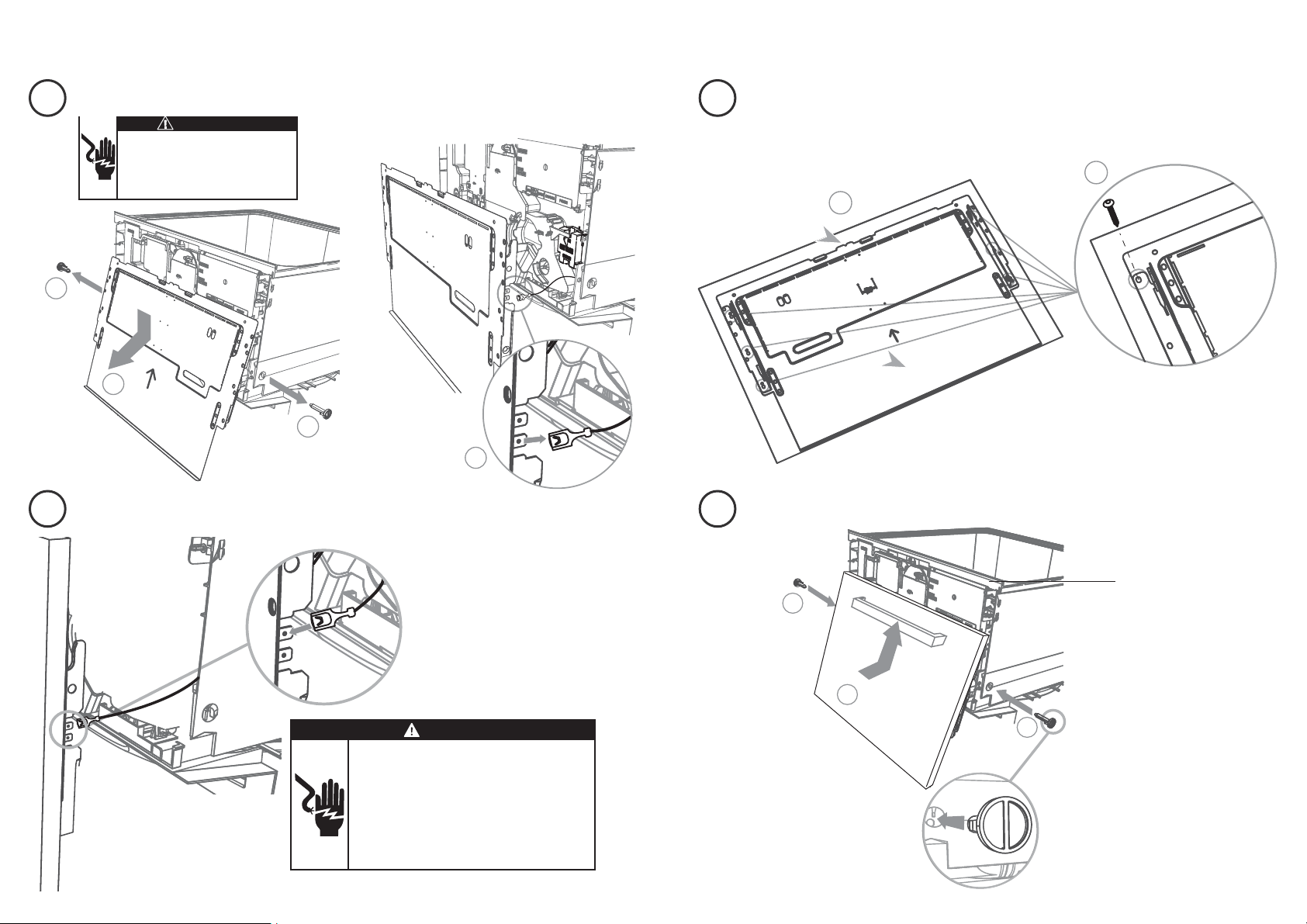
INTEGRATED MODELS ONLY - INSTALLING THE FRONT PANEL
1
2
16 mm x6
2
2
1
Important!
Ensure the rubber seal
between the drawer
and panel is kept in
place.
REMOVE BRACKET FROM PRODUCT
ATTACH PANEL TO PRODUCTGROUND THE PANEL
ATTACH PANEL TO PANEL BRACKET
There must be at least
3 screws used each side
When refitting the
door pins,
ensure they are
orientated as shown.
Align bottom of panel
with bottom of bracket
18
20
19
21
⁄” (16mm) x6
3
1
1
2
Electrical Shock Hazard
Before continuing, ensure that the product is
disconnected from the power supply.
Failure to follow this warning may result in
electrical shock, injury or re.
WARNING!
WARNING!
To ground (earth) the panel bracket, connect
the ground (earth) wire from the product to
one of the tabs. Any custom metal component
(e.g. handle) that extends past the rubber seal
must be grounded (earthed) too.
Failure to follow these warnings may result in
electrical shock, injury or re.
Electrical Shock Hazard
19
INTEGRATED MODELS ONLY - INSTALLING THE FRONT PANEL
ADJUST PANEL HEIGHT TO ALIGN THE CABINETRY GAPS
22
With the front panels fitted, insert an appropriately
sized Philips screwdriver into the hole above the door
pin and rotate the panels up or down to align the gaps
in your cabinetry.
Repeat on the other side if necessary.
The panel has a maximum travel of ⁄” (2 mm) up or
down.
Important!
Ensure that you maintain a minimum of ⁄” (2 mm)
ventilation gap below the panel.
+ or - ⁄” (2 mm)
20
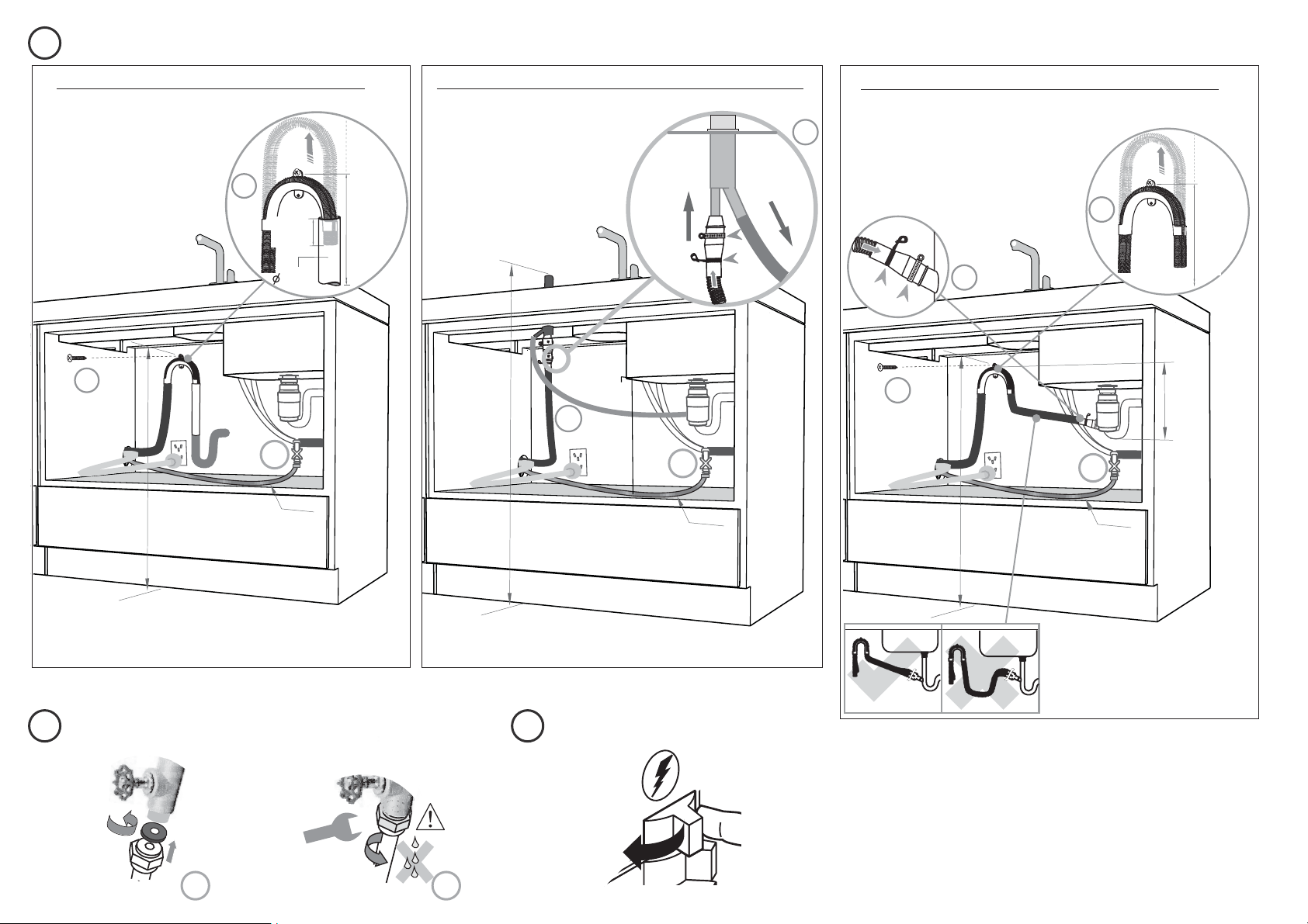
THERE ARE THREE DIFFERENT PLUMBING AND DRAINAGE OPTIONS. CHOOSE WHICH IS MORE SUITABLE.
23
1
3
750-882.5 mm
*
2
1
*
2
1
38 mm
max.
120
mm
750-882.5 mm
*
2
*
If space is limited
for fixing, push
hose through drain
hose support
to required height
If space is limited
for fixing, push
hose through drain
hose support
to required height
Ensure drain hose is routed straight
to joiner. Remove excess drain hose
material if necessary.
Do not shorten the inlet hose.
Dishwasher using sink trap with drain hose joiner
Dishwasher using Air Break with Drain Hose Joiner
29½ ”-34¾ ”
(750-882.5 mm)
min. R 8”
(200 mm)
min. R 8”
(200 mm)
min. R 8”
(200 mm)
1½ ”
(38 mm)
max.
4¾ ”
(120mm)
29 ½ ”-34 ¾ ”
(750-882.5 mm)
29 ½ ”-34 ¾ ”
(750-882.5 mm)
Supplied drain hose joiner
Ø ¾ ” (19 mm) waste tee
Dishwasher and Standpipe Ø 1½ ” (38 mm)
HIGHLOOP
min. 6”
(150 mm)
CONNECT INLET HOSE TO HOT WATER SWITCH PRODUCT ON
24 25
34
Ensure the
supplied
rubber
washer is
fitted inside
the coupling.
Tighten coupling with wrench.
180
o
No leaks!
1 2
Important!
Ensure that drain connection
will comply with local plumbing
regulations.
24
24
24
37 ⁄”
(
950 mm)
Max. height to
top of Air Break
(countertop or
wall mounted)
see
see
see

21
27
26
FINAL CHECKLIST TROUBLESHOOTING
Check all parts are installed.
Ensure product is level, securely fastened to the cabinetry and opens and
closes freely. The drawer must be free to fully close with no resistance from the
cabinetry.
Ensure inlet hose to water supply has supplied rubber washer fitted, and that
it’s tightened a further half turn after seal contact.
Ensure any knockouts or plugs in drain connection have been drilled out and
drain connection has been made.
The drain hose joiner must not support the weight of excess hose material.
Keep drain hose as fully extended as possible to prevent sagging. Any excess
length of drain hose should be kept on the dishwasher side of the highloop.
If connecting the drain hose to the sink trap, ensure the Highloop is a minimum
6” (150 mm) higher than the drain hose joiner.
Ensure any packaging or tape securing the racks is removed from the drawer.
Turn on the power and water supplies, then open the drawer. You should hear a
beep and see a program indicator light up on the internal control panel.
Check the spray arm is in place and free to rotate.
Add three cups of water into the drawer. Press
on the internal control panel
until the indicator of the ‘Rinse’ program lights up. Close the drawer and press
to start the program.
After the Rinse program has finished, ensure the dishwasher has run and
drained correctly.
Check water supply and drainage connection for leakage.
Spray arm
Excessive water remaining above the filter plate, after the rinse cycle
Check for a kinked drain hose or blocked waste connection, highloop not
properly installed or drain hose not routed correctly.
No water supply (This is displayed as a ‘U1’ fault -- see section ‘If there is a
fault’ in the User guide for how to recognise this fault on models without a
display.)
Check water is connected and turned on.
The dishwasher is beeping continuously
There is a fault. See section ‘If there is a fault’ in the User guide for further
information and instructions.
No program indicator lights up when the drawer is opened
Ensure power is connected and is switched on. If it is and still no indicator
lights up, see the ‘Preference options’ section of the ‘Quick start guide’. An
option called ‘Open drawer auto power-on’ may need to be turned on.
Water around water supply and drainage connections
Check connections, existing plumbing and hoses for leaks. Check rubber
washer and hose clamp are correctly fitted.
If product is tipping
Ensure the product is secured to the cabinetry.
If front panels are misaligned
Check and relevel product. Check the cabinetry is square. For Integrated
models, check and adjust front panel alignment if necessary.
Drawer doesn’t close properly
Ensure nothing is obstructing the drawer from closing properly eg sound
insulation, hoses or drawer latches.
If a problem occurs, consult the ‘Troubleshooting’ section of the User guide.
If after checking these points you still need assistance, please refer to the
Service & Warranty book for warranty details and your nearest Authorized
Service Center, or contact us through our website, listed below.
Important!
SAVE THESE INSTRUCTIONS
The models shown in this document may not be available in all markets and are subject to change
at any time. For current details about model and specification availability in your country, please
visit our website listed at the end of this document or contact your local Fisher & Paykel dealer.
www. sherpaykel.com