Loading ...
Loading ...
Loading ...
8
3.5 INSTALLING NON-INSULATED DUCTS AND DIFFUSERS (CONT’D)
3. INSTALLATION (CONT’D)
Stale air exhaust ductwork
Same as for Fully Ducted System, described in step 3.5.1
3.5.2 CENTRAL DRAW POINT (AS ILLUSTRATED IN SECTION 2.2)
Fresh air distribution ductwork
When performing duct connections, always use approved tools and materials. Respect all corresponding
laws and safety regulations. Please refer to your local building code.
WARNING
!
Method 2: Return side connection
• Locate the opening for fresh air ductwork on the forced air unit return duct at a
minimum linear distance of 9’ 10” upstream (from forced air unit drop: A+B+C).
Cut out a 5” Ø hole in this location, using metal shear.
• Use a metal transition to connect the unit duct to the forced air unit return duct.
• Attach the other end of the flexible duct to the Fresh air to building port (see icon
on the left side of the unit). Use tie wrap and duct tape to seal the connection.
See illustration at right.
VJ0099
A + B + C = NOT LESS
THAN 9’ 10”
UNIT DOOR
METAL
TRANSITION
When performing connection to the furnace supply duct, this duct must be sized to support the additional
air flow produced by the HRV/ERV. Also, use a metal duct with a backdraft damper to prevent the risk of
overheating the HRV/ERV.
CAUTION
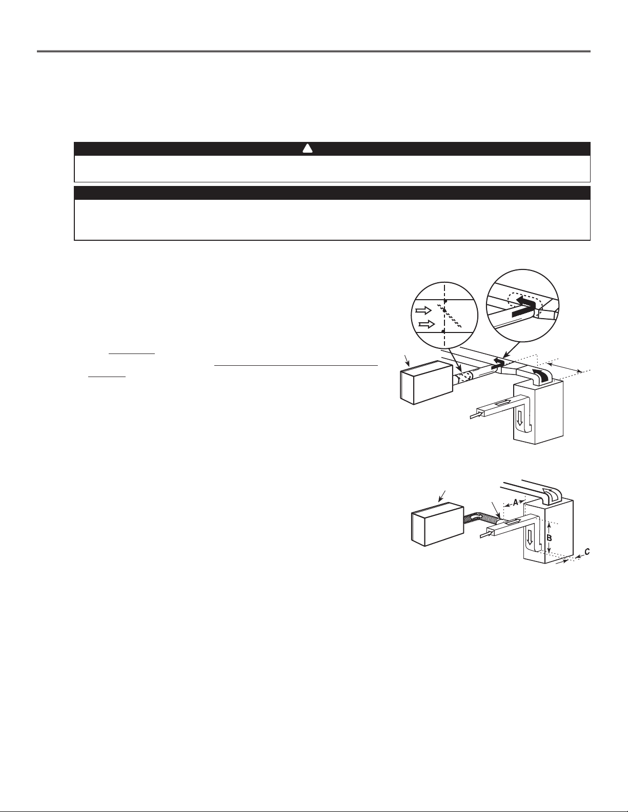
There are 2 methods for connecting the unit to the furnace:
Method 1: Supply side connection
• Cut an opening into the furnace supply duct at least 18” from the furnace.
• Connect this opening to the fresh air distribution port of the HRV/ERV
(use metal duct, see figure at right).
• Make sure that the HRV/ERV duct forms an elbow inside the furnace
ductwork.
• If desired, interlock (synchronize) the furnace blower operation with the
HRV/ERV operation (see Section 5).
VJ0108
MINIMUM 18”
UNIT DOOR
METAL DUCT WITH
BACKDRAFT DAMPER
Loading ...
Loading ...
Loading ...