INSTALLATION GUIDE
VB0235
These products earned the ENERGY STAR
®
by meeting strict energy efficiency guidelines set by Natural Resources
Canada and the US EPA. They meet ENERGY STAR requirements only when used in Canada.
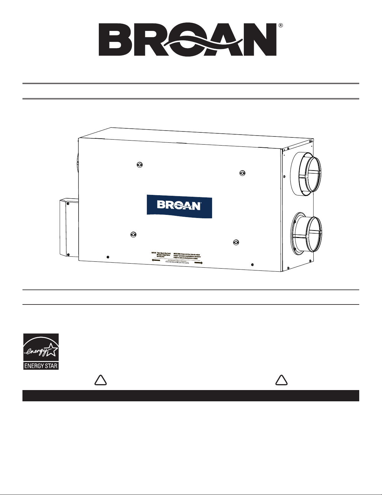
RESIDENTIAL INDOOR USE ONLY
! !
READ AND SAVE THESE INSTRUCTIONS
22734 rev. 03
MODELS HRVH100S AND ERVH100S
Broan-NuTone LLC; Hartford, Wisconsin www.broan.com 800-543-3055
REGISTER YOUR PRODUCT ONLINE AT: www.broan.com/register
For additional information - visit www.broan.com
2
Please take note that this manual uses the following symbols to emphasize particular information:
Identifies an instruction which, if not followed, might cause serious personal injuries including possibility of death.
Identifies an instruction which, if not followed, may severely damage the unit and/or its components.
NOTE: Indicates supplementary information needed to fully complete an instruction.
WARNING
!
CAUTION
ABOUT THIS GUIDE
ABOUT THESE UNITS
LIMITATION
For residential (domestic) installation only. Installation work and electrical wiring must be done by a qualified person(s) in accordance with
all applicable codes and standards, including fire-rated construction codes and standards.
WARNING
!
TO REDUCE THE RISK OF FIRE, ELECTRIC SHOCK, OR INJURY TO PERSON(S) OBSERVE THE FOLLOWING:
1. Use this unit only in the manner intended by the manufacturer. If you have questions, contact the manufacturer at the address or
telephone number listed in the warranty.
2. We recommend that your unit be inspected by a specialized technician once a year.
3. Before servicing or cleaning the unit, disconnect power cord from electrical outlet.
4. This unit is not designed to provide combustion and/or dilution air for fuel-burning appliances.
5. When cutting or drilling into wall or ceiling, do not damage electrical wiring and other hidden utilities.
6. Do not use this unit with any solid-state speed control device other than following optional main and auxiliary wall controls:
7. This unit must be grounded. The power supply cord has a 3-prong grounding plug for your personal safety. It must be plugged into a
mating 3-prong grounding receptacle, grounded in accordance with the national electrical code and local codes and ordinances. Do
not remove the ground prong. Do not use an extension cord.
8. Do not install in a cooking area or connect directly to any appliances.
9. Do not use to exhaust hazardous or explosive materials and vapors.
10. When performing installation, servicing or cleaning the unit, it is recommended to wear safety glasses and gloves.
11. Due to the weight of the unit, two installers are recommended to perform installation.
12. When applicable local regulations comprise more restrictive installation and/or certification requirements, the aforementioned
requirements prevail on those of this document and the installer agrees to conform to these at his own expenses.
CAUTION
1. To avoid prematurate clogged filters, turn OFF the unit during construction or renovation.
2. Please read specification label on product for further information and requirements.
3. Be sure to duct air outdoor – Do not intake/exhaust air into spaces within walls or ceiling or into attics, crawl spaces, or garage.
4. Intended for residential installation only in accordance with the requirements of NFPA 90B.
5. Do not run any air ducts directly above or closer than 2 ft to any furnace or its supply plenum, boiler, or other heat producing appliance.
If a duct has to be connected to the furnace return plenum, it must be connected not closer than 9’ 10” from this plenum connection to
the furnace.
6. The ductwork is intended to be installed in compliance with all applicable codes.
7. When leaving the house for a long period of time (more than two weeks), a responsible person should regularly check if the unit
operates adequately.
8. If the ductwork passes through an unconditioned space (e.g.: attic), the unit must operate continuously except when performing
maintenance and/or repair. Also, the ambient temperature of the house should never drop below 65°F.
Optional Main Controls Optional Auxiliary Controls
VT8W, VT7W, VT4W and VT6W 59W and VB60W
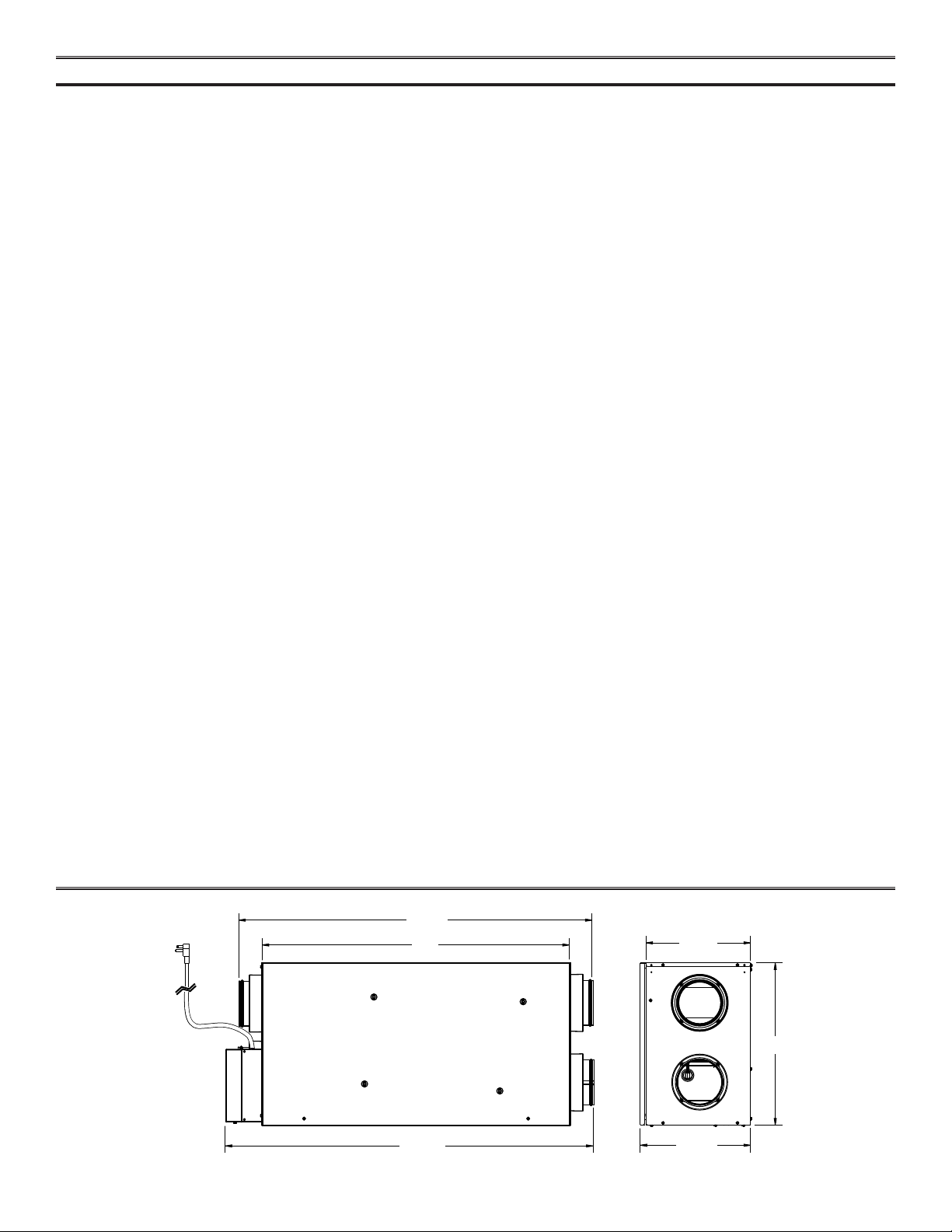
TABLE OF CONTENTS
3
1. D IMENSIONS . . . . . . . . . . . . . . . . . . . . . . . . . . . . . . . . . . . . . . . . . . . . . . . . . . 3
2. TYPICAL INSTALLATIONS. . . . . . . . . . . . . . . . . . . . . . . . . . . . . . . . . . . . . . . . . . . . . . 4
2.1 FULLY DUCTED SYSTEM . . . . . . . . . . . . . . . . . . . . . . . . . . . . . . . . . . . . . . . . . . . . . . . 4
2.2 CENTRAL DRAW POINT . . . . . . . . . . . . . . . . . . . . . . . . . . . . . . . . . . . . . . . . . . . . . . . . 4
2.3 SIMPLIFIED INSTALLATION . . . . . . . . . . . . . . . . . . . . . . . . . . . . . . . . . . . . . . . . . . . . . . . 4
3. INSTALLATION . . . . . . . . . . . . . . . . . . . . . . . . . . . . . . . . . . . . . . . . . . . . . . . . 5-11
3.1 INSPECT THE CONTENT OF THE BOX . . . . . . . . . . . . . . . . . . . . . . . . . . . . . . . . . . . . . . . . . . 5
3.2 TOOLS AND MATERIAL . . . . . . . . . . . . . . . . . . . . . . . . . . . . . . . . . . . . . . . . . . . . . . . . 6
3.3 LOCATING THE UNIT . . . . . . . . . . . . . . . . . . . . . . . . . . . . . . . . . . . . . . . . . . . . . . . . . 6
3.4 PLANNING OF THE DUCTWORK . . . . . . . . . . . . . . . . . . . . . . . . . . . . . . . . . . . . . . . . . . . . . 6
3.5 INSTALLING NON-INSULATED DUCTS AND DIFFUSERS . . . . . . . . . . . . . . . . . . . . . . . . . . . . . . . . . . 7-9
3.5.1 FULLY DUCTED SYSTEM . . . . . . . . . . . . . . . . . . . . . . . . . . . . . . . . . . . . . . . . . . . . . . . . . . 7
3.5.2 CENTRAL DRAW POINT . . . . . . . . . . . . . . . . . . . . . . . . . . . . . . . . . . . . . . . . . . . . . . . . . . 8
3.5.3 SIMPLIFIED INSTALLATION. . . . . . . . . . . . . . . . . . . . . . . . . . . . . . . . . . . . . . . . . . . . . . . . . . 9
3.6 INSTALLING INSULATED FLEXIBLE DUCTS . . . . . . . . . . . . . . . . . . . . . . . . . . . . . . . . . . . . . . . 10
3.6.1 CONNECTION TO THE UNIT PORTS . . . . . . . . . . . . . . . . . . . . . . . . . . . . . . . . . . . . . . . . . . . . .10
3.6.2 LOCATING EXTERIOR PORTS . . . . . . . . . . . . . . . . . . . . . . . . . . . . . . . . . . . . . . . . . . . . . . . .10
3.7 CONNECTING INSULATED DUCTS TO EXTERIOR PORTS . . . . . . . . . . . . . . . . . . . . . . . . . . . . . . . . . 11
3.8 INSTALLING TANDEM
®
TRANSITION KIT . . . . . . . . . . . . . . . . . . . . . . . . . . . . . . . . . . . . . . . . 11
3.9 CONNECTING THE DRAIN . . . . . . . . . . . . . . . . . . . . . . . . . . . . . . . . . . . . . . . . . . . . . . 11
4. CONTROLS . . . . . . . . . . . . . . . . . . . . . . . . . . . . . . . . . . . . . . . . . . . . . . . . . 12-14
4.1 INTEGRATED CONTROL . . . . . . . . . . . . . . . . . . . . . . . . . . . . . . . . . . . . . . . . . . . . . . . 12
4.2 BOOTING SEQUENCE . . . . . . . . . . . . . . . . . . . . . . . . . . . . . . . . . . . . . . . . . . . . . . . . 12
4.3 SETTING EXTENDED DEFROST . . . . . . . . . . . . . . . . . . . . . . . . . . . . . . . . . . . . . . . . . . . . 12
4.4 ELECTRICAL CONNECTION TO OPTIONAL WALL CONTROLS . . . . . . . . . . . . . . . . . . . . . . . . . . . . . .13-14
4.4.1 ELECTRICAL CONNECTION TO VT8W MAIN WALL CONTROL . . . . . . . . . . . . . . . . . . . . . . . . . . . . . . . . . .13
4.4.2 ELECTRICAL CONNECTION TO VT7W MAIN WALL CONTROL . . . . . . . . . . . . . . . . . . . . . . . . . . . . . . . . . .13
4.4.3 ELECTRICAL CONNECTION TO VT4W MAIN WALL CONTROL . . . . . . . . . . . . . . . . . . . . . . . . . . . . . . . . . .13
4.4.4 ELECTRICAL CONNECTION TO VT6W MAIN WALL CONTROL . . . . . . . . . . . . . . . . . . . . . . . . . . . . . . . . . .13
4.4.5 ELECTRICAL CONNECTION TO OPTIONAL AUXILIARY WALL CONTROLS . . . . . . . . . . . . . . . . . . . . . . . . . . . . . .14
5. ELECTRICAL CONNECTION TO THE FURNACE . . . . . . . . . . . . . . . . . . . . . . . . . . . . . . . . . . . 15
6. WIRING DIAGRAM . . . . . . . . . . . . . . . . . . . . . . . . . . . . . . . . . . . . . . . . . . . . . . . 16
7. B ALANCING THE UNIT. . . . . . . . . . . . . . . . . . . . . . . . . . . . . . . . . . . . . . . . . . . . . . 17
8. SERVICE PARTS . . . . . . . . . . . . . . . . . . . . . . . . . . . . . . . . . . . . . . . . . . . . . . . . 18
9. TROUBLESHOOTING . . . . . . . . . . . . . . . . . . . . . . . . . . . . . . . . . . . . . . . . . . . . .19-20
1. DIMENSIONS
11¼ "
17
7
/16"
37
7
/8"
33"
11
7
/8"
VK0086A
39 /8"
4
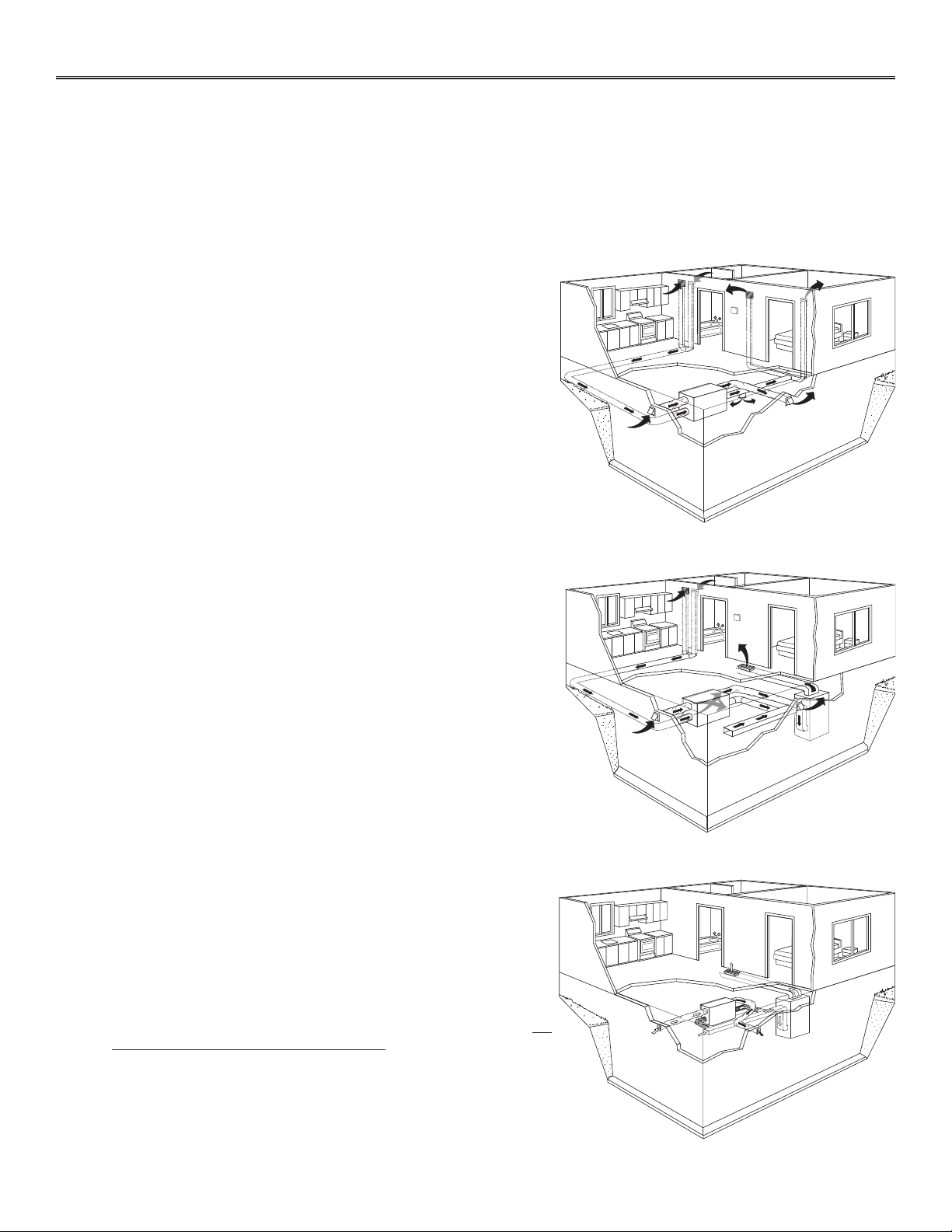
2. TYPICAL INSTALLATIONS
Use the following illustrations as guidelines to help you decide on how the unit will be installed.
All the units should be hung from the joists.
In every case, bathroom fans and a range hood could be used to exhaust stale air. Also, for homes with more than one level, we recommend
one exhaust register at the highest level.
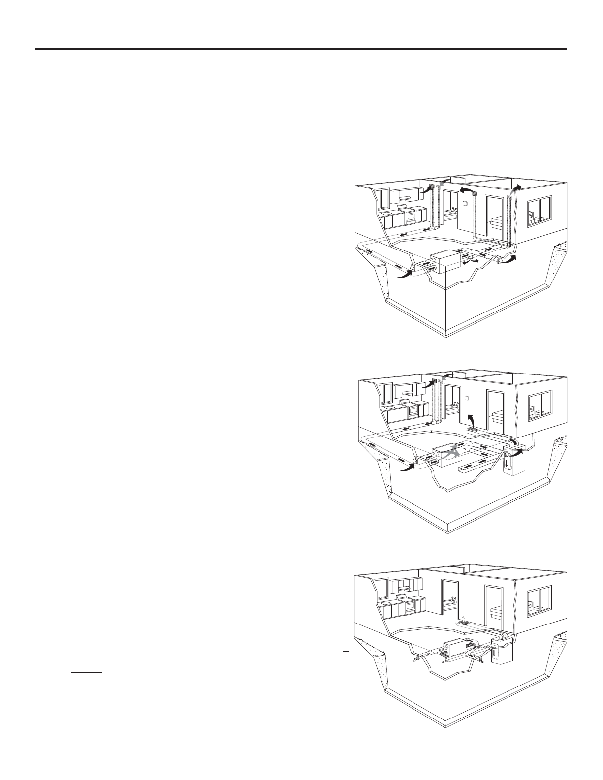
There are 3 installation methods: Fully Ducted System, Central Draw Point and Simplified Installation.
NOTE: An electrical outlet has to be available within 3 feet of the unit.
2.1 FULLY DUCTED SYSTEM (PRIMARILY FOR HOMES WITH RADIANT HOT WATER OR ELECTRIC BASEBOARD HEATING)
VH0024
Stale air coming from the register located at the highest level of the
house is exhausted to the outdoor. Fresh air from outdoor is filtered and
supplied by the register located in the lowest liveable level.
Homes with more than one level require at least one exhaust register at
the highest level.
See figure at right.
2.2 CENTRAL DRAW POINT (CONNECTION TO A FORCED AIR SYSTEM)
VH0025
Stale air coming from the register located at the highest level of the
house is exhausted to the outdoor. Fresh air from outdoor is filtered and
supplied to the return (plenum) or the supply duct of the forced air unit.
See figure at right.
For this type of installation, it is not essential that the forced air system
blower runs when the unit is in operation, but we recommend it.
NOTE: Home with multiple forced air systems should have one unit on
each system.
2.3 SIMPLIFIED INSTALLATION (CONNECTION TO A FORCED AIR SYSTEM)
VH0093
Stale air is exhausted to the outdoor. Fresh air from outdoor is filtered
and supplied to the return (plenum) or the supply duct of the forced air
unit.
See figure at right.
To avoid cross-contamination and achieve the highest efficiencies, the
forced air system blower must always be ON.
NOTE: Home with multiple forced air systems should have one unit on
each system.
5
3. INSTALLATION
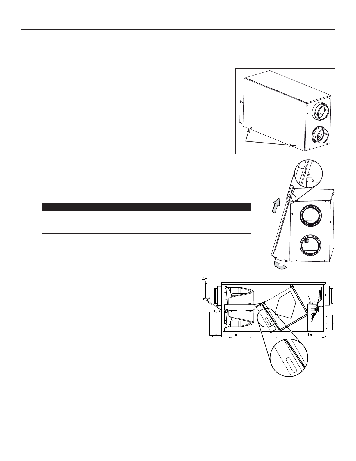
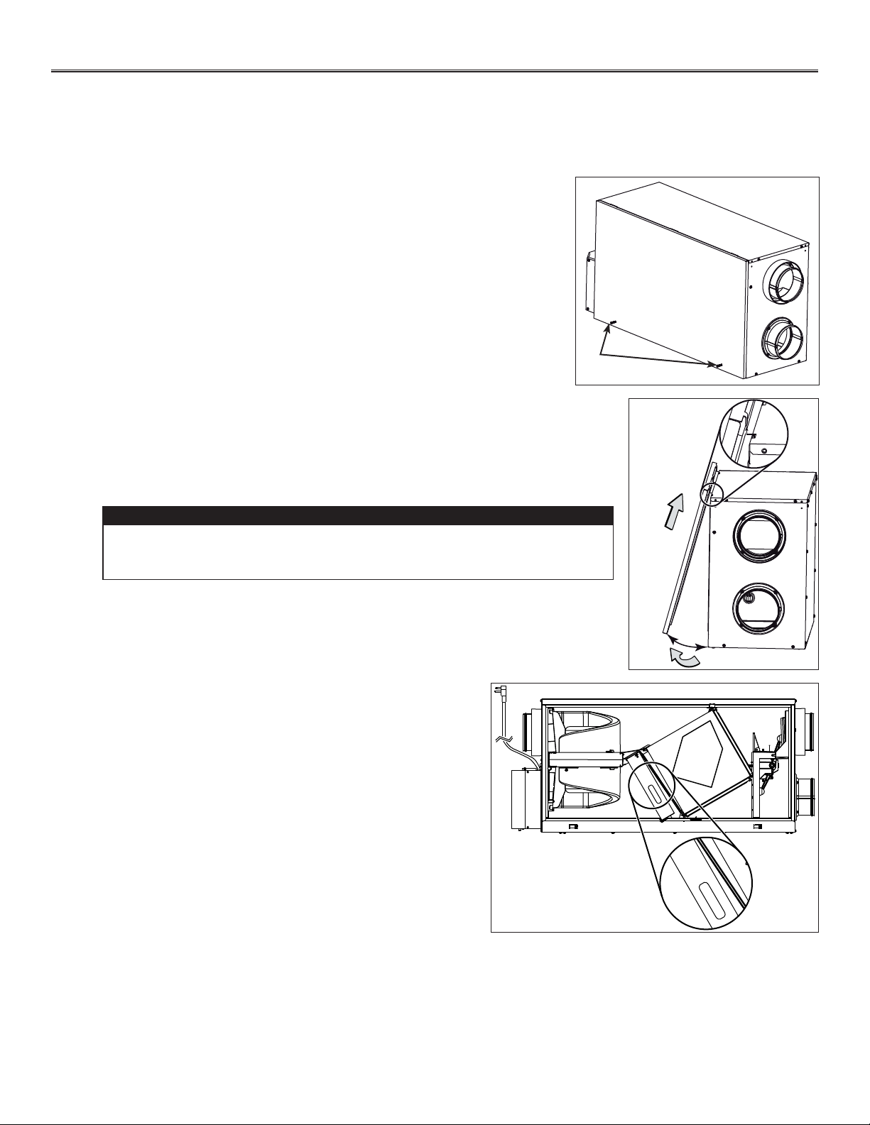
• Inspect the exterior of the unit for shipping damage. Ensure that there is no damage to the door, ports, power cord, etc.
• Remove the transport tape over the heat or energy recovery core
of the unit.
• Inspect the inside of the unit for damage. Ensure that blower
assembly, heat or energy recovery core, core filters, insulation,
dampers, prefilter and HEPA filter, etc. are all intact, then reinstall
the door.
NOTE: Write the installation date on the HEPA filter frame for future
reference (see illustration at right).
TOP
DESSUS
FRONT
AVANT
Instal. date:
Date d’instal. :
__ / __ / ____
21293
FRONT
AVANT
Instal. date:
Date d’instal. :
__ / __ / ____
VD0322
NOTE: Before proceeding to the installation, check the content of the box. Remove all packaging material from the unit.
In order to prevent damages to the door hooks, do not open completely the
unit door; tilt it about 3" from the unit base and lift it up. See illustration at
right.
CAUTION
±3”
VD0303A
B
C
VD0302
A
• Using a Phillips or a Robertson screwdriver, loosen both door screws (A).
NOTE: The screws will stay attached to the door.
• Open (B) and lift out (C) the door.
3.1 INSPECT THE CONTENT OF THE BOX
6
3. INSTALLATION (CONT’D)
3.3 LOCATING THE UNIT
Choose an appropriate location for the unit.
• Within an area of the house where the ambient temperature is kept between 50°F and 104°F.
• Away from living areas (dining room, living room, bedroom), if possible.
• So as to provide easy access to the interior of the unit, for maintenance.
• Close to an exterior wall, so as to limit the length of the insulated flexible duct to and from the unit.
• Away from hot chimneys and other fire hazards.
• Allow for a power source (standard 3-prong grounding outlet).
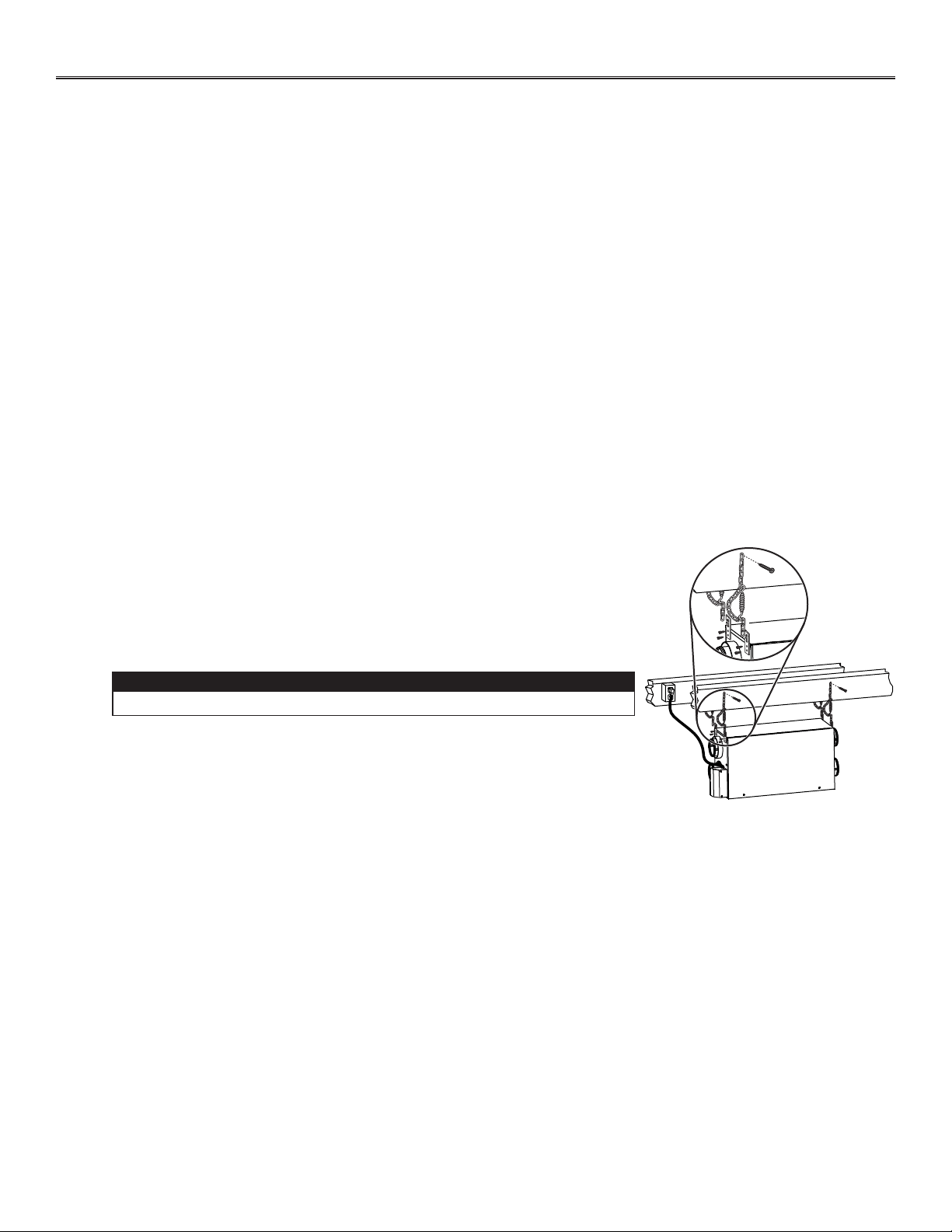
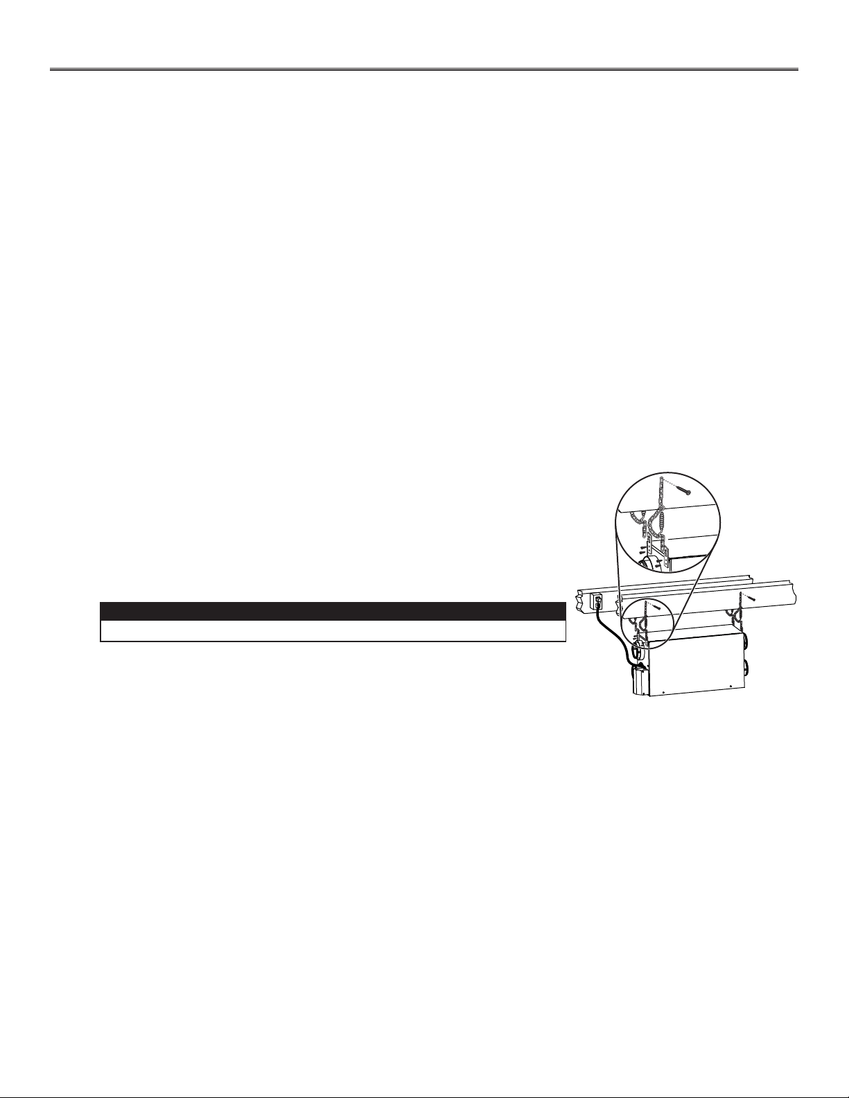
• FOR HRV UNITS ONLY: Close to a drain. If no drain is close by, use a pail to collect
run-off.
Hang the unit with the four hooks, chains and springs provided. See illustration at right.
VD0305
Make sure the unit is level.
CAUTION
3.2 TOOLS AND MATERIAL
Following are the tools and material needed:
• Phillips no. 2 or Robertson no. 2 screwdriver
• Small flat blade screwdriver (for wall control connection)
• Wire stripper (for wall control connection)
• Hammer and flat blade screwdriver (for plenum or supply furnace duct connection installation only, to make holes in existing
metal duct)
• Scissors or utility knife (to cut duct tape)
• Measuring tape
• Duct tape
• Tin snips or metal shear (for plenum or supply furnace duct connection installation only, to cut ductwork)
• Aluminum duct tape (for plenum connection installation only)
• Jig saw
• Caulking gun and caulking.
3.4 PLANNING OF THE DUCTWORK
• Keep it simple. Plan for a minimum of bends and joints.
• Keep the length of insulated ducts to a minimum.
• Do not ventilate crawl spaces or cold rooms. Do not attempt to recover the exhaust air from a dryer or a range hood. This
would cause clogging of the filters and recovery module.
• If the house has two floors or more, be sure to plan for at least one exhaust register on the highest lived-in level.
7
HOW TO CONNECT THE FLEXIBLE DUCTS TO THE DIFFUSERS
Once the diffusers location is determined, cut out 5¼” diameter hole.
Run one end of the flexible duct through the hole and fix it to the diffuser base (1),
using a tie wrap and duct tape. Assemble the diffuser base to the wall (or ceiling)
using its 4 no. 8 x 3/4” screws. Then, slide in the diffuser (2).
See illustration at right.
Ø 5¼”
VJ0094A
2
1
3. INSTALLATION (CONT’D)
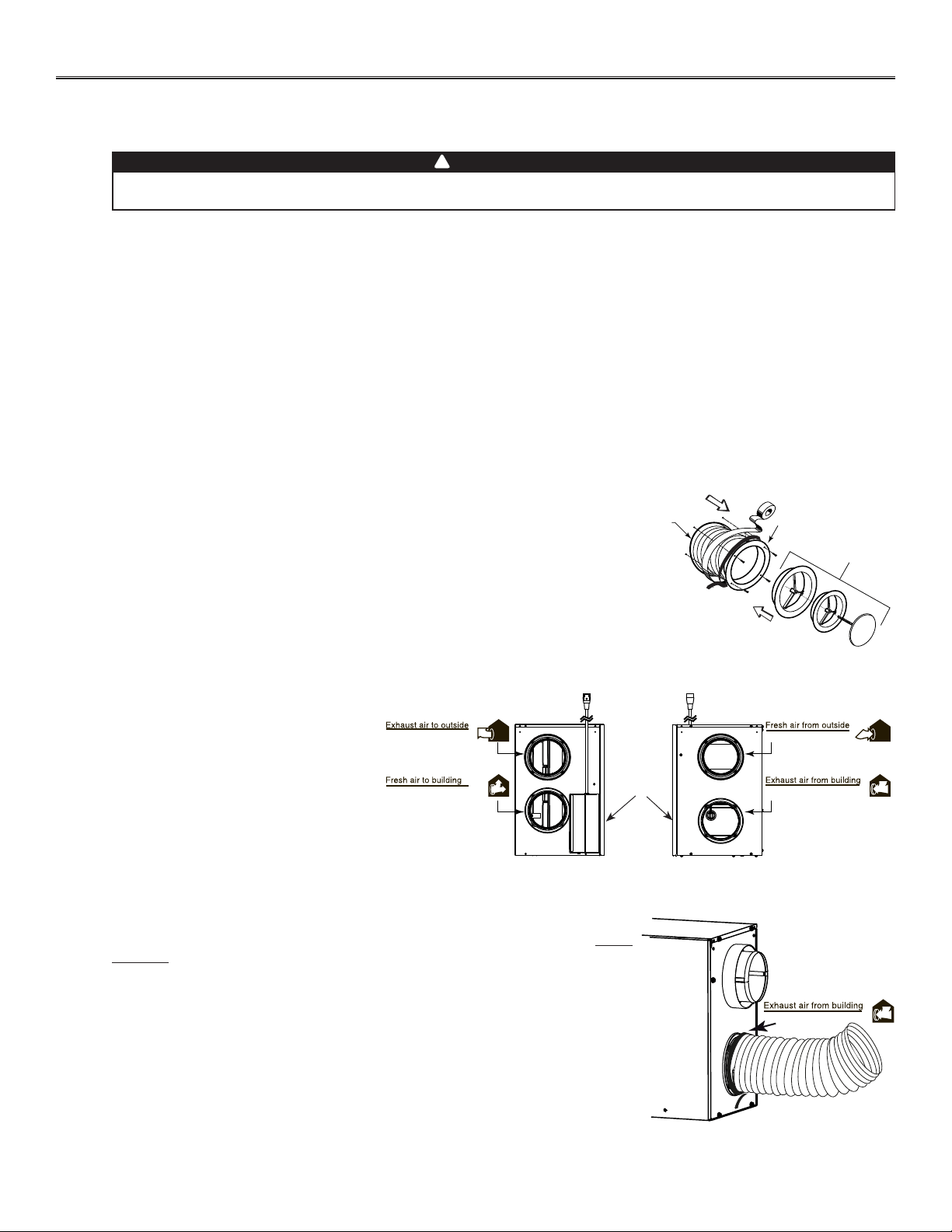
HOW TO CONNECT THE FLEXIBLE DUCTS TO THE UNIT PORTS
Both flexible ducts attached to the diffusers must be connected to the bottom ports of
the unit. When facing the unit door, the fresh air to building port is located on left side
and the exhaust air from building port is on the right side. Refer to the identification
labels affixed beside each unit ports. Using tie wrap, attach the fresh air to building
duct to its corresponding port, then do the same for the exhaust air to building duct
and port. See illustration at right.
NOTE: Use an insulated duct if the duct will have to go through a space where it is
possible to experience extreme temperature conditions (eg: in northern area,
unheated attic in winter or uncooled attic in southern area). Also, if you plan to
stop the unit for more than 12 hours, we recommend to cover the duct with R12
insulation.
VJ0107
Aire de salida desde el interior
RIGHT SIDE OF THE UNIT
Fresh air distribution ductwork
• Install the fresh air distribution diffuser in a large, open area in the lowest level to ensure the greatest possible air circulation.
• Keep in mind that the fresh air diffuser must be located as far as possible from the stale air diffuser. If desired, you can install
another diffuser.
• Install the diffuser either in the ceiling OR 6 to 12 inches from the ceiling on an interior wall. (The cooler air will then cross the
upper part of the room and mix with room air, before descending to occupant’s level.)
• If a register must be floor installed, direct the airflow up the wall.
UNIT PORTS IDENTIFICATION
Each unit port has an identification label
beside it to avoid wrong duct connections to
the unit. Always refer to these labels before
performing any duct and port connection.
VJ0106
Aire de salida hacia el exterior
Aire fresco hacia el interior
Aire fresco desde el exterior
Aire de salida desde el interior
UNIT
DOOR
Stale air exhaust ductwork
• Install the stale air exhaust diffuser in the main area where the contaminants are produced: kitchen, living room, etc. Position
the diffuser as far from the stairway as possible and in such a way that the air circulates in all the lived-in spaces in the house.
If desired, you can install another diffuser (sold separately).
• If a diffuser is installed in the kitchen, it must be located at least 4 feet from the range.
• Install the diffuser 6 to 12 inches from the ceiling on an interior wall OR install it in the ceiling.
Never install a stale air exhaust diffuser in a closed room where a combustion device operates, such as a
gas furnace, a gas water heater or a fireplace.
WARNING
!
3.5 INSTALLING NON-INSULATED DUCTS AND DIFFUSERS
3.5.1 FULLY DUCTED SYSTEM (AS ILLUSTRATED IN SECTION 2.1)
8
3.5 INSTALLING NON-INSULATED DUCTS AND DIFFUSERS (CONT’D)
3. INSTALLATION (CONT’D)
Stale air exhaust ductwork
Same as for Fully Ducted System, described in step 3.5.1
3.5.2 CENTRAL DRAW POINT (AS ILLUSTRATED IN SECTION 2.2)
Fresh air distribution ductwork
When performing duct connections, always use approved tools and materials. Respect all corresponding
laws and safety regulations. Please refer to your local building code.
WARNING
!
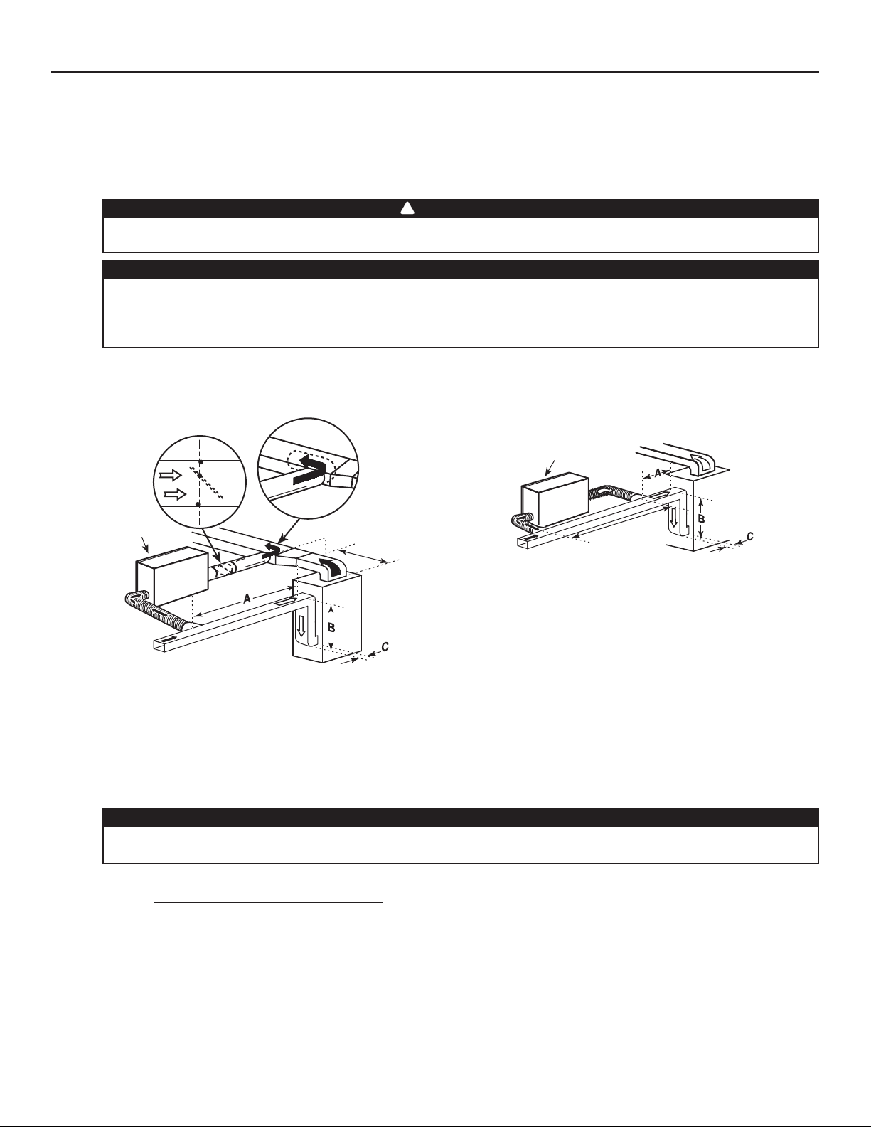
Method 2: Return side connection
• Locate the opening for fresh air ductwork on the forced air unit return duct at a
minimum linear distance of 9’ 10” upstream (from forced air unit drop: A+B+C).
Cut out a 5” Ø hole in this location, using metal shear.
• Use a metal transition to connect the unit duct to the forced air unit return duct.
• Attach the other end of the flexible duct to the Fresh air to building port (see icon
on the left side of the unit). Use tie wrap and duct tape to seal the connection.
See illustration at right.
VJ0099
A + B + C = NOT LESS
THAN 9’ 10”
UNIT DOOR
METAL
TRANSITION
When performing connection to the furnace supply duct, this duct must be sized to support the additional
air flow produced by the HRV/ERV. Also, use a metal duct with a backdraft damper to prevent the risk of
overheating the HRV/ERV.
CAUTION
There are 2 methods for connecting the unit to the furnace:
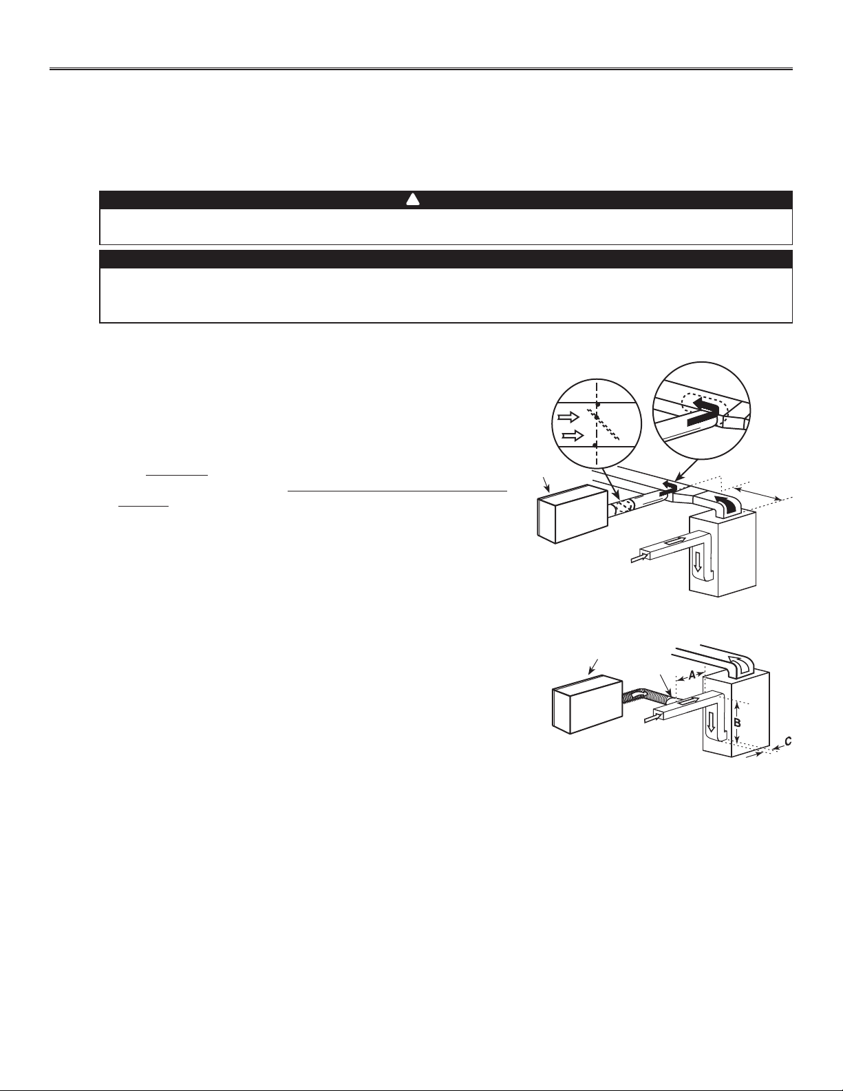
Method 1: Supply side connection
• Cut an opening into the furnace supply duct at least 18” from the furnace.
• Connect this opening to the fresh air distribution port of the HRV/ERV
(use metal duct, see figure at right).
• Make sure that the HRV/ERV duct forms an elbow inside the furnace
ductwork.
• If desired, interlock (synchronize) the furnace blower operation with the
HRV/ERV operation (see Section 5).
VJ0108
MINIMUM 18”
UNIT DOOR
METAL DUCT WITH
BACKDRAFT DAMPER
9
3.5 INSTALLING NON-INSULATED DUCTS AND DIFFUSERS (CONT’D)
3. INSTALLATION (CONT’D)
Fresh air distribution ductwork (return side connection)
Same as for Central Draw Point, described in step 3.5.2
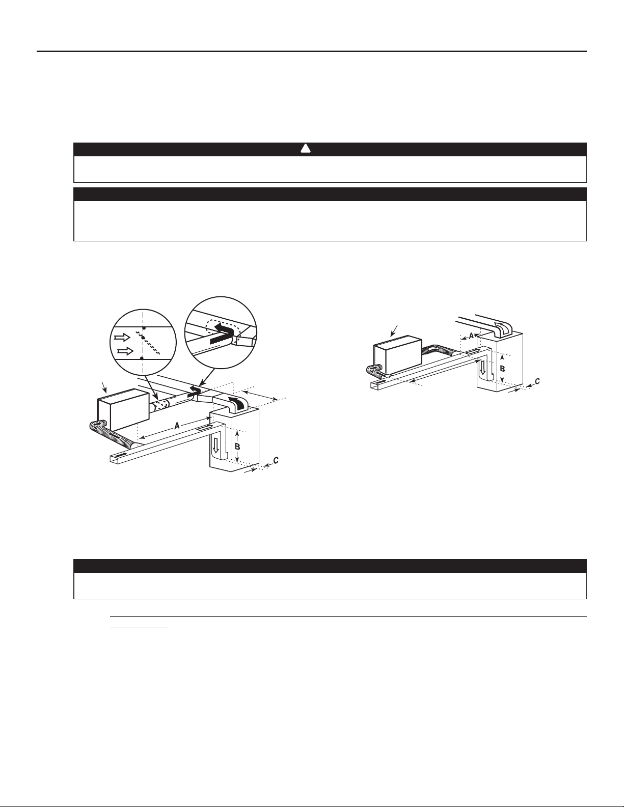
3.5.3 SIMPLIFIED INSTALLATION (AS ILLUSTRATED IN SECTION 2.3)
Stale air exhaust ductwork (return side connection)
When performing duct connections, always use approved tools and materials. Respect all corresponding
laws and safety regulations. Please refer to your local building code.
WARNING
If using Method 2, make sure the furnace blower operation is synchronized with the HRV/ERV operation!
See Section 5.
CAUTION
!
VJ0109
3’MINIMUM
UNIT DOOR
A + B + C = NOT LESS
THAN 9’ 10”
When performing connection to the furnace supply duct, this duct must be sized to support the additional
air flow produced by the HRV/ERV. Also, use a metal duct with a backdraft damper to prevent the risk of
overheating the HRV/ERV.
CAUTION
There are 2 methods for connecting the unit to the furnace:
Method 1: Return-supply connection Method 2: Return-return connection
VJ0110
MINIMUM 18”
UNIT DOOR
METAL DUCT WITH
BACKDRAFT DAMPER
A + B + C = NOT LESS
THAN 9’ 10”
Stale air intake:
• Cut an opening into the furnace return duct not less than 9’ 10” from forced air unit drop: (A+B+C).
• Connect this opening to the stale air intake port on the HRV/ERV as shown.
Fresh air distribution: (Same instruction as for Method 1 or Method 2, section 3.5.2)
For Method 2 (return-return), make sure there is a distance of at least 3 feet between both connections to the furnace.
NOTE: For Method 1, it is not essential to synchronize the furnace blower operation with the HRV/ERV operation, but we
recommend it.

10
3. INSTALLATION (CONT’D)
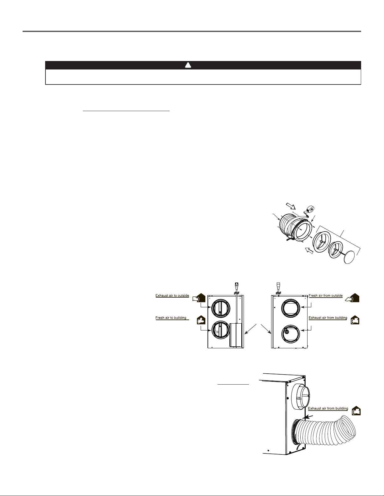
3.6 INSTALLING INSULATED FLEXIBLE DUCTS
Make sure the vapor barrier on the insulated ducts does not tear during installation to avoid condensation
within the ducts.
CAUTION
Use the following procedure for connecting the insulated flexible ducts to the unit ports (Exhaust air to outdoor and Fresh air from
outdoor). Refer to identification labels before performing any duct and port connection.
For both remaining ducts, pull back the insulation to expose
the interior flexible duct.
Connect the interior flexible duct to the smaller part of the
inner ring of the port using a tie wrap.
Pull the insulation over the joint and tuck it between the
inner and outer rings of the port. Pull the vapor barrier over
the insulation and over the outer ring of the port.
Apply duct tape gently to the joint in order to make an airtight
seal. See figures at right.
3.6.1 CONNECTION TO THE UNIT PORTS
VJ0102
Avoid compressing the insulation when you pull the tape tightly around the joint. Compressed insulation
loses its insulation properties and causes water dripping due to condensation on the exterior surface of
the duct.
CAUTION
Choose an appropriate location for installing the exterior ports:
• There must be a minimum distance of 6’ between the hoods to avoid cross-contamination
• There must be a minimum distance of 18” from the ground
3.6.2 LOCATING EXTERIOR PORTS
Make sure the fresh air intake port is
located at least 6 feet away (or more, as per
applicable building codes or standards)
from sources of contamination such as:
• Dryer exhaust, high efficiency furnace
vent, central vacuum vent
• Gas meter exhaust, gas barbecue grill
• Garbage bin
• Any exhaust from a combustion source.
WARNING
!
VD0203
6’
6’
STALE AIR
EXHAUST PORT
18’’
18’’
5’’ Ø
18’’
FRESH AIR
INTAKE PORT
OPTIONAL
LOCATION
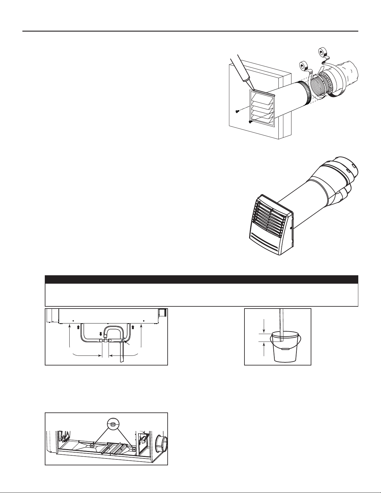
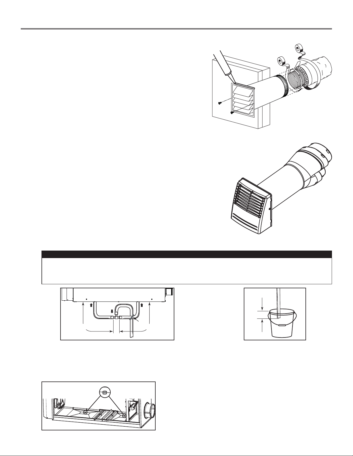
3.7 CONNECTING INSULATED DUCTS TO EXTERIOR PORTS
• For each exterior port, using a jig saw, cut a 5’’ diameter hole in the
exterior wall.
• From the outdoor, slide the exterior port in place and attach it to the
exterior wall, using 2 no. 8 x 1½” provided screws. Seal the outline with
silicone.
• From the inside, pull back the insulation to expose the flexible duct and,
using a tie wrap, attach it to the exterior port rigid duct. Carefully seal
with duct tape. Pull the insulation over the joint. Pull the vapor barrier
over the insulation and over the joint. Apply gently duct tape to the joint
making an airtight seal. See illustration at right.
VR0028
3. INSTALLATION (CONT’D)
11
3.8 INSTALLING TANDEM
®
TRANSITION* KIT
If desired, it is possible to perform insulated ducts connection with the outdoor
using the Tandem transition kit (purchase separately, part number VTYIK1). The
joist opening needed to install the Tandem transition must be 9¾” minimum. The
maximum height of the Tandem transition is 8¾”. To connect the insulated flexible
ducts to the Tandem transition (Exhaust air to outdoor and Fresh air from outdoor),
follow the instructions included with the kit.
*Patented.
VR0003
Tandem transition kit
3.9 CONNECTING THE DRAIN
Cut two sections of plastic tubing, approximately
12” long, and connect each one to both inner drain
fittings located under the unit as shown.
Join these both sections to the “T” junction and
main tube as shown, to prevent the unit from
drawing unpleasant odors from the drain source.
VD0308A
± 1”
Run the tube to the floor drain or to an alternative
drain pipe or pail.
IMPORTANT
If using a pail to collect water, locate the tube end
approximately 1” from the top of the pail in order to
prevent water from being drawn back up into the unit.
VD0311A
± 12” ± 12”
TIE WRAP
A drain tubing (included) must be installed for all HRV units. For ERV units, it is not required, however, it is
recommended for climates where the outdoor temperature typically remains below -13°F, (over a 24-hour
period) for several days in a row, combined with an indoor humidity of 40% or higher.
CAUTION
NOTES: 1. For ERV unit, remove both drain plugs inside the unit prior to
install tubing.
2. ERV core and blower assembly removed from illustration to ease
understanding.
VD0323
12
4. CONTROLS
4.2 BOOTING SEQUENCE
The unit booting sequence is similar to a personal computer boot sequence. Each time the unit is plugged after being unplugged, or
after a power failure, the unit will perform a 30-second booting sequence before starting to operate.
During the booting sequence, the integrated defrost control LED will light AMBER for 5 seconds, and then will shut off for 2 seconds.
After that, the LED will light RED for the rest of the booting sequence. During this RED light phase, the unit is checking and resetting
the motorized damper position. Once the motorized damper position completely set, the RED light turns off and the booting sequence
is done.
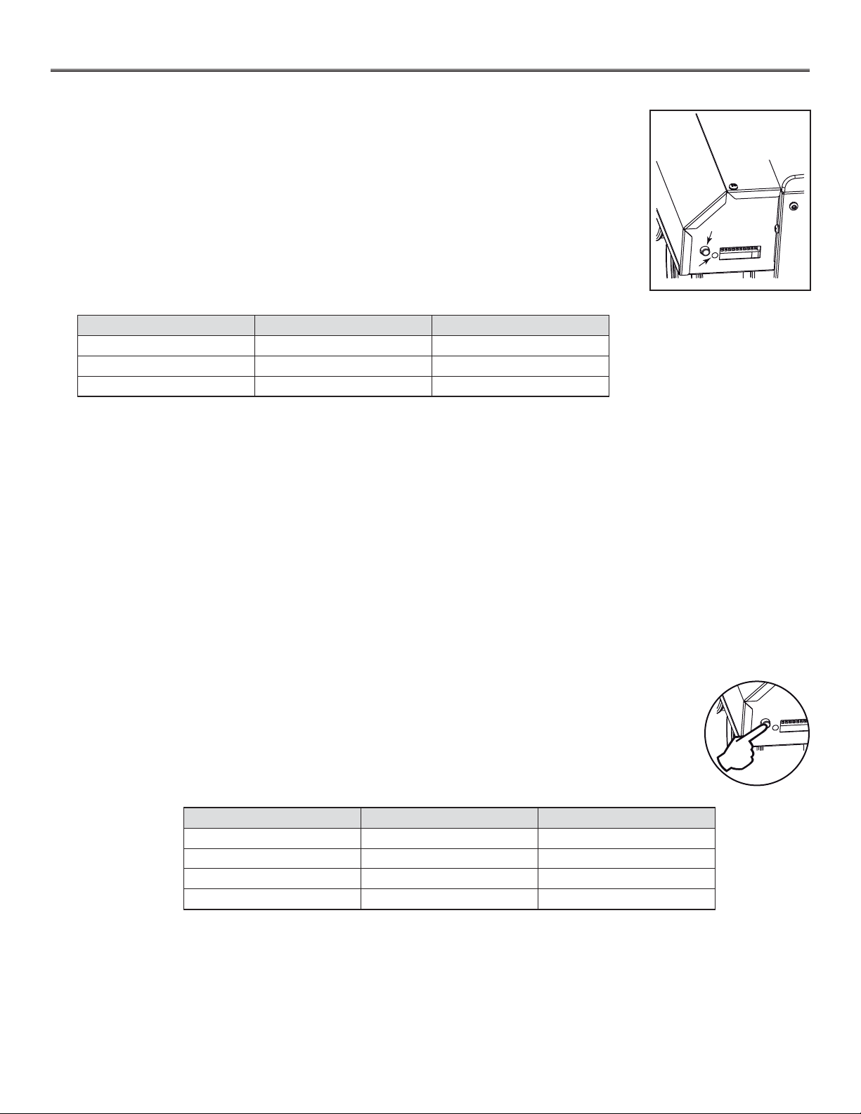
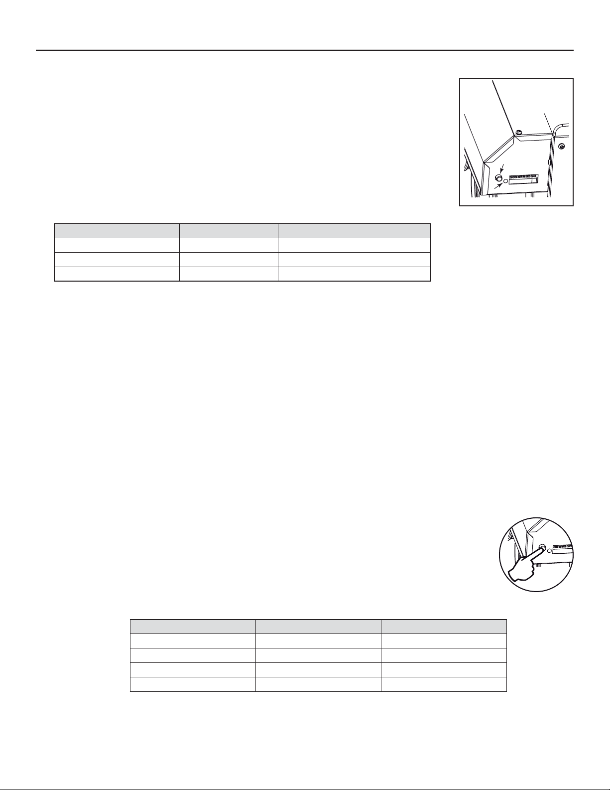
4.3 SETTING EXTENDED DEFROST
The unit is factory set to normal defrost. In cold region (outdoor temperature -17°F and lower), it may be
necessary to setup extended defrost. During the first 3 seconds of booting sequence, while the integrated
control LED is AMBER, press on push button for about 3 seconds. The LED will blink GREEN the number of times
corresponding to the actual defrost mode of the unit.
NOTE: During setting extended defrost, while the push button is pressed, the LED will light RED to indicate
the signal has been received.
Refer to table below to modify the defrost cycle of the unit. It is possible to change the selection as many times
needed.
DEFROST CYCLE PRESS ON PUSH BUTTON LED BLINKS GREEN
1 NORMAL (HRV UNIT)ONCE 1 TIME
2 EXTENDED (HRV UNIT)TWICE 2 TIMES
3 NORMAL (ERV UNIT)THREE TIMES 3 TIMES
4 EXTENDED (ERV UNIT)FOUR TIMES 4 TIMES
If a problem occurs during the unit operation, its integrated control LED (2) will blink. The color of the blinking light depends on the
type of error detected. Refer to Section 9 Troubleshooting on last pages for further details.
NOTE: The integrated control must be turned OFF to use an optional main control.
VD0324
4.1 INTEGRATED CONTROL
These units are equipped with an integrated control located under the electrical compartment of the
unit. Use the push button (1) to control the unit; the LED (2) will then show which mode the unit is in
(see illustration at right).
PRESS ON PUSH BUTTON LED COLOR RESULTS
ONCE AMBER UNIT IS ON LOW SPEED
TWICE GREEN UNIT IS ON HIGH SPEED
THREE TIMES NO LIGHT UNIT IS OFF
1
2
VD0310
Refer to table below to see how to operate the unit using its integrated control.
To exit setting extended defrost, press 3 seconds on push button OR wait 60 seconds; the LED will blink and shut off, then light RED
(the unit returns in its booting sequence).
13
4. CONTROLS (CONT’D)
4.4 ELECTRICAL CONNECTION TO WALL CONTROLS
For more convenience, this unit can also be controlled using an optional main wall control.
NOTES: 1. The integrated control must be turned OFF to use an optional main control.
2. If an optional auxiliary control is used, if activated, this auxiliary control will override the optional main control.
WARNING
Always disconnect the unit before making any connections. Failure in disconnecting power could result in electric
shock or damage of the wall control or electronic module inside the unit.
!
CAUTION
Never install more than one main wall control per unit. Make sure that the wires do not short-circuit between
themselves or by touching any other components on the wall control. Avoid poor wiring connections. To reduce
electrical interference (noise) potential, do not run wall control wiring next to control contactors or near light
dimming circuits, electrical motors, dwelling/building power or lighting wiring, or power distribution panel.
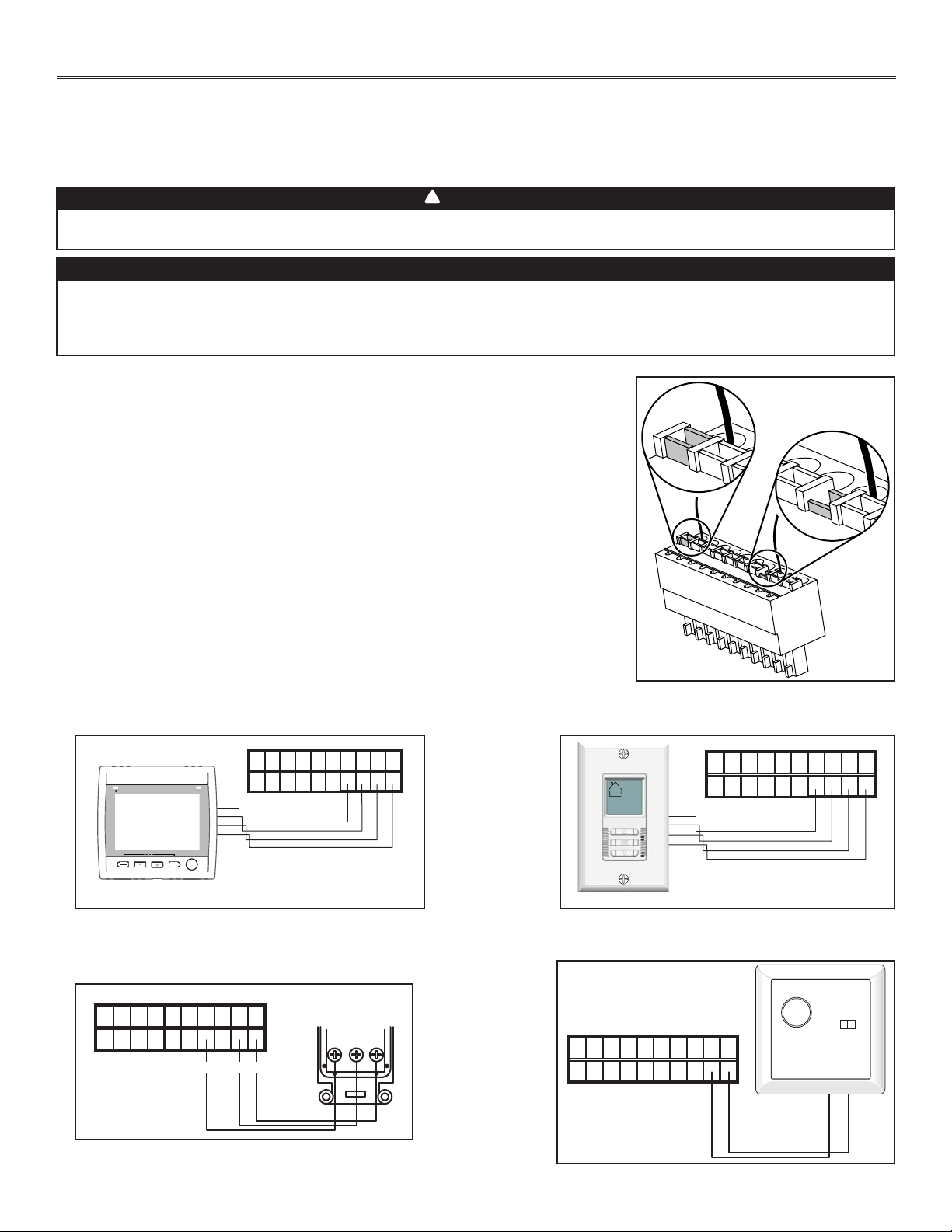
Use the terminal connector included in the installation kit to perform the electrical connection for
main and optional wall controls. Check if all wires are correctly inserted in their corresponding
holes in the terminal block. (A wire is correctly inserted when its orange receptacle is lower
than another one without wire. On picture at right, wire A is correctly inserted, but not wire B.)
4.4.1 ELECTRICAL CONNECTION TO VT8W
MAIN WALL CONTROL
4.4.2 ELECTRICAL CONNECTION TO VT7W MAIN
WALL CONTROL
4.4.3 ELECTRICAL CONNECTION TO
VT4W MAIN WALL CONTROL
4.4.4 ELECTRICAL CONNECTION TO VT6W
MAIN WALL CONTROL
NO C NC I OC OL Y R G B
VE0181
SMART
SET
MODE
PREF
NO C NC I OC OL Y R G B
VE0250
NO C NC I OC OL Y R G B
B G
G
B
Y
VE0328A
Y
NO C NC I OC OL Y R G B
VE0187
VE0272
A
B
VT4W
MAIN WALL CONTROL
REAR VIEW
4. CONTROLS (CONT’D)
14
VE0273
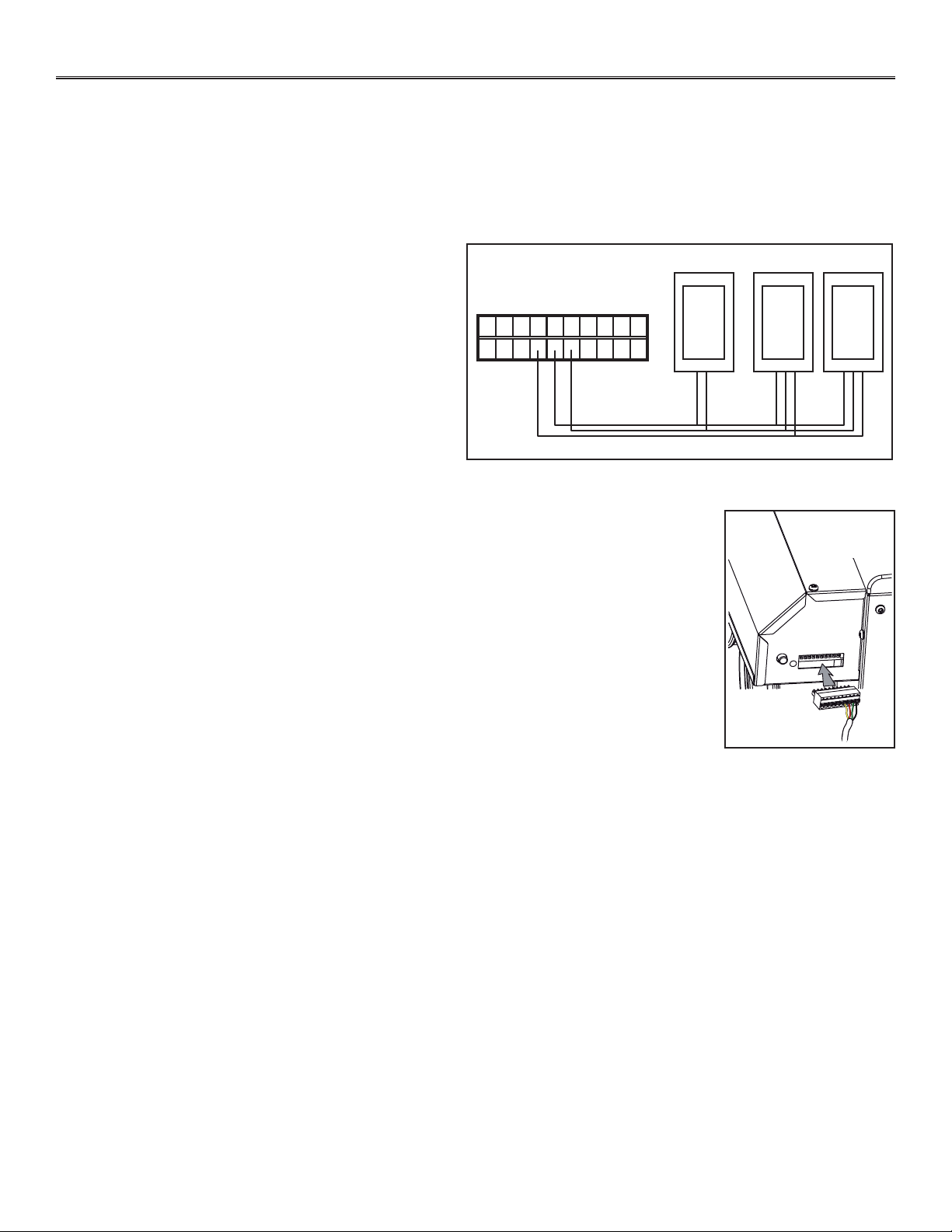
Once the control(s) connections have been made, insert the terminal connector in the electrical
compartment interface. Plug the unit.
NOTE: Refer to Main and auxiliary wall control User Guide (included with the ventilation unit and also
available at www.broan.com) for information about the use of optional main and auxiliary wall controls.
4.4 ELECTRICAL CONNECTION TO WALL CONTROLS (CONT’D)
4.4.5 ELECTRICAL CONNECTION TO OPTIONAL AUXILIARY
WALL CONTROLS
NO C NC I OC OL Y R G B
VE0371
59W
VB60W
5. ELECTRICAL CONNECTION TO THE FURNACE
15
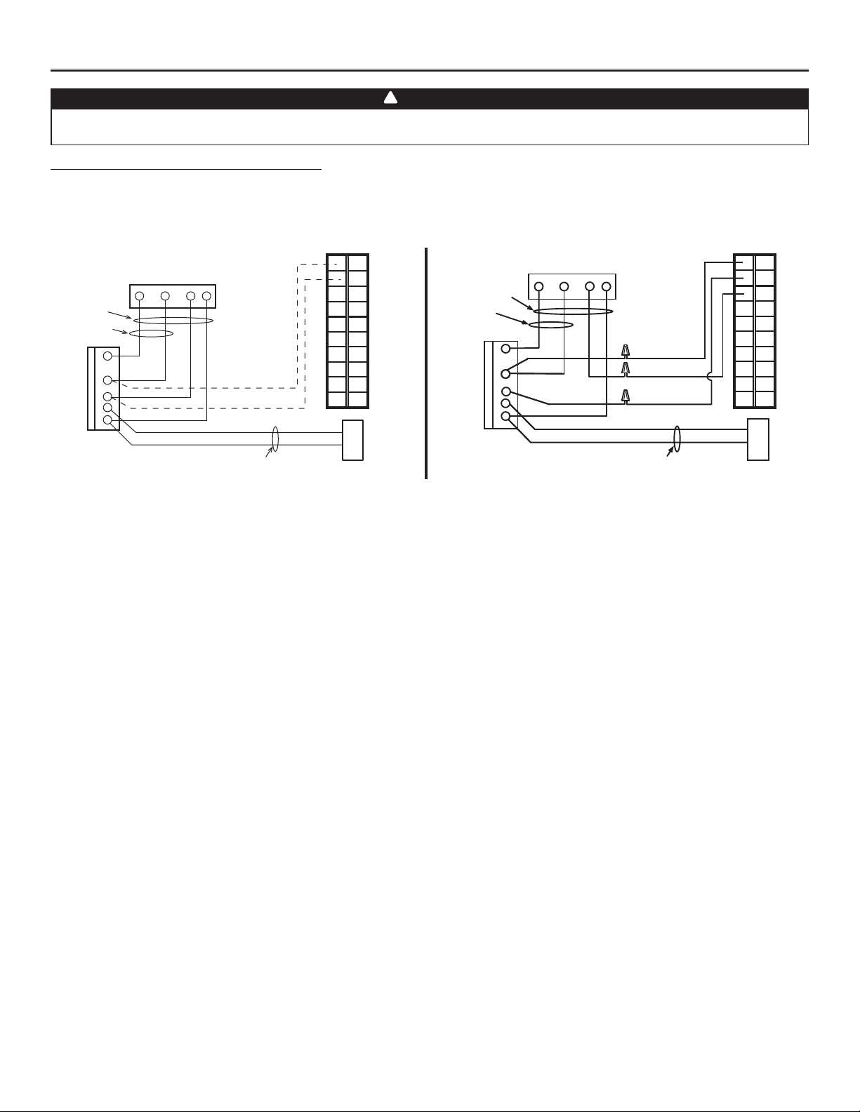
For a furnace connected to a cooling system:
On some older thermostat, energizing the “R” and “G” terminals at the furnace has the effect of energizing “Y” terminal at the thermostat
and thereby turning on the cooling system. If you identify this type of thermostat, you must use the ALTERNATE FURNACE INTERLOCK WIRING.
WARNING
Never connect a 120-volt AC circuit to the terminals of the furnace interlock (standard wiring). Use only the low
voltage class 2 circuit of the furnace blower control.
!
W R G
Y
W
R
G
C
Y
UNIT TERMINAL CONNECTOR
THERMOSTAT
TERMINALS
FOUR
WIRES
TWO WIRES
heating only
FURNACE
24-VOLT
TERMINAL BLOCK
TWO WIRES
COOLING SYSTEM
NO C NC I OC OL Y R G B
W R G Y
W
R
Y
R
G
Y
C
THERMOSTAT
TERMINAL
4 WIRES
2 WIRES
heating only
wiring
nuts
FURNACE
24-VOLT
TERMINAL BLOCK
2 WIRES
COOLING SYSTEM
NO
NC
C
UNIT TERMINAL CONNECTOR
NO C NC I OC OL Y R G B
VE0108A
STANDARD FURNACE INTERLOCK WIRING ALTERNATE FURNACE INTERLOCK WIRING
6. WIRING DIAGRAM
16
WARNING
!
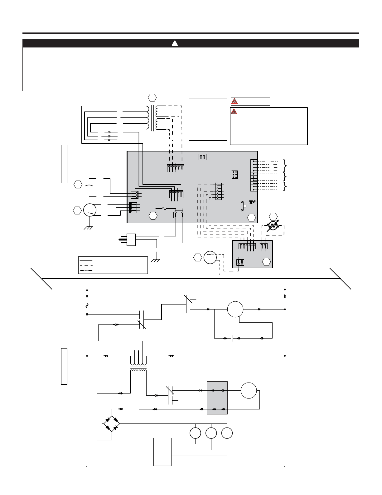
WIRING DIAGRAM
Critical characteristic.
NOTES
1. Use specified UL listed/CSA Certified line fuse.
2. If any of the original wire, as supplied, must
be replaced, use the same equivalent wire.
3. Field wiring must comply with applicable
codes, ordinances and regulations.
4. Remote control (class 2 circuit) available,
see instruction manual.
COLOR CODE
BK BLACK
BL BLUE
BN BROWN
G GREEN
RRED
WWHITE
Y YELLOW
nc no connection
OORANGE
P PURPLE
Line voltage factory wiring
Class 2 low voltage factory wiring
Class 2 low voltage field wiring
J11
12
T1
24 V
Class 2
9.5 V
Class 2
O
O
Y
Y
120 V
106 V
81 V
71 V
Neutral
W
BK
BL
P
BN
R
nc
nc
BN
P
BL
J8
12345
J14
10
9
8
7
6
5
4
3
2
1
J13
ICP
1 2 3 4 5
J12
J9
1234
3A
3 AG Type
21
J10
ELECTRONIC ASSEMBLY
A1
F1
Override switch
(optional; see
notes 3 & 4)
R1
Thermistor
J2
J1
1234512
J3
12
A2
DAMPER
ELECTRONIC ASSEMBLY
M2
Damper
Motor
BK
BK
BK
W
G
120 Volts AC
60 Hz
J6
J4
2
1
1
2
3
BK
BL
BN
Fan motor
M1
C1
Motor
capacitor
BK
BK
BK
G
Y
BK
G
R
Y
OL
OC
I
Field wiring
remote control
(see notes 3 & 4)
See note 1
120 V AC
Line
Neutral
J10-2 J10-1
F1 K2
K3
Fan motor M1
M
M
Damper motor M2
J4-1 J4-2
C1
Motor capacitor
J4-3J6-1 J6-2
J9-4
A2
J2-1 J3-1
J2-2 J3-2
J12-1
J12-2
K4
J8-2
J8-1
J8-5
J8-4
9.5 V AC
24 V AC
T1
nc nc
106 VAC
81 VAC
71 VAC
J9-3
J9-1
~
~
+-
CPU
K4K3K2
LOGIC DIAGRAM
VE0291A
R
Furnace blower
interlock (optional;
see notes 3 & 5)
5. Furnace fan circuit must be class 2 circuit only.
• Risk of electric shocks. Before performing any maintenance or servicing, always disconnect the unit from its power source.
• This product is equipped with an overload protection (fuse). A blown fuse indicates an overload or a
short-circuit situation. If the fuse blows, unplug the product and check the polarity and voltage output from the
outlet. Replace the fuse as per the servicing instructions (refer to wiring diagram for proper fuse rating) and
verify the product. If the replaced fuse blows, it may be a short-circuit and the product must be discarded or
returned to an authorized service center for examination and/or repair.
VP0009
7. B ALANCING THE UNIT
17
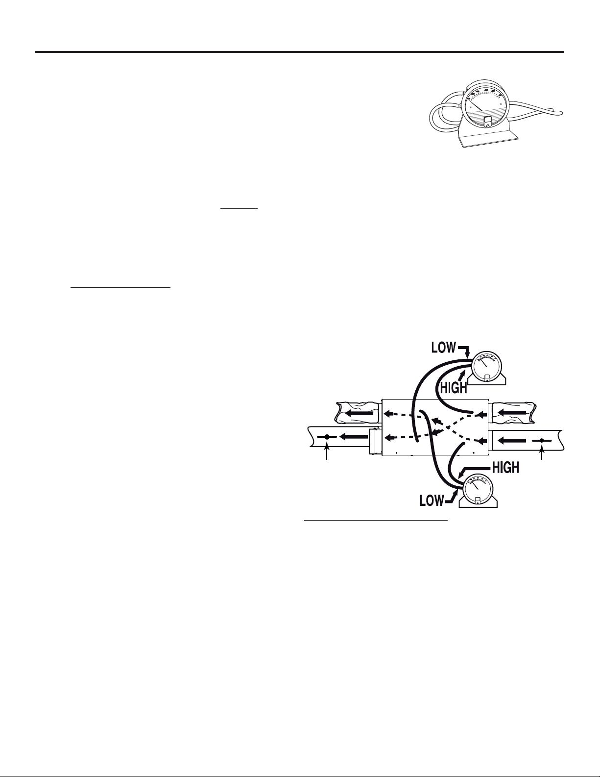
7.1 WHAT YOU NEED TO BALANCE THE UNIT
• A magnehelic gauge capable of measuring 0 to 0.5 inch of water (0 to 125 Pa) and 2 plastic
tubes.
• The balancing chart located on the unit door.
7.2 PRELIMINARY STAGES TO BALANCE THE UNIT
• Seal all the unit ductwork with tape. Close all windows and doors.
• Turn off all exhaust devices such as range hood, dryer and bathroom fans.
• Make sure the balancing dampers are fully open.
NOTE: The balancing dampers are NOT INCLUDED; to be supplied by others. Install the balancing dampers in Fresh air to
building duct and exhaust air from building duct (A and B on illustration below), at the more convenient place.
• Make sure all filters are clean (if it is not the first time you balance the unit).
7.3 BALANCING PROCEDURE
1. Set the unit to high speed.
Make sure that the furnace/air handler blower is ON if the installation is in any way connected to the ductwork of the cold air
return. If not, leave furnace/air handler blower OFF. If the outdoor temperature is below 32°F, make sure the unit is not running in
defrost while balancing. (By waiting 10 minutes after plugging the unit in, you are assured that the unit is not in a defrost cycle.)
2. Place the magnehelic gauge on a level surface and adjust it to zero.
3. Connect tubing from gauge to exhaust air flow pressure taps
(see illustration at right).
Be sure to connect the tubes to their appropriate high/low
fittings. If the gauge drops below zero, reverse the tubing
connections.
NOTE: It is suggested to start with the exhaust air flow
reading because the exhaust has typically more
restriction than the fresh air, especially in cases of
fully ducted installations or source point ventilation.
Place the magnehelic gauge upright and level.
Record equivalent air flow of the reading according
to the balancing chart.
4. Move tubing to fresh air flow pressure taps (see diagram).
Adjust the fresh air balancing damper (A) until the fresh air
flow is approximately the same as the exhaust air flow. If
fresh air flow is less than exhaust air flow, then go back and adjust the exhaust balancing damper (B) to equal the fresh air flow.
5. Secure both dampers in place with a fastening screw.
6. Write the required air flow information on a label and affix it near the unit for future reference (date, maximum speed air flows,
your name, phone number and business address).
NOTE: The unit is considered balanced even if there is a difference of ±10 cfm (or ± 5 l/s) between the two air flows.
VP0024
AB
EXHAUST
AIR FLOW
FRESH
AIR FLOW

18
8. SERVICE PARTS
1
2
3
4
5
6
7
8
9
11
12
13
14
VL0062
10
ITEM DESCRIPTION QTY. HRVH100S ERVH100S
1TRANSFORMER 1 SV61545 SV61545
2ELECTRONIC BOARD 1 SV61415 SV61184
3CAPACITOR 6 F 1 SV61550 SV61550
4BLOWER ASSEMBLY 1 SV61552 SV61552
5CORE BRACKET 1 SV61553 SV61553
6DOOR ASSEMBLY 1 SV63625 SV63625
7HEPA FILTER KIT¹ 1 SV21293 SV21293
8PREFILTER KIT FOR HEPA FILTER² 1 SV61561 SV61561
9CORE FILTER 2 SV61563 SV61562
10 BOTTOM FILTER RETAINING WIRE 1 SV61564
11 DAMPER SYSTEM ASSEMBLY 1 SV61565 SV61565
12
HEAT RECOVERY CORE 1 SV61567
ENERGY RECOVERY CORE 1 SV61410
13 BRACKET WITH RETAINING NUT 2 SV61411 SV61411
14 DOUBLE COLLAR PORT 2 SV61569 SV61569
REPLACEMENT PARTS AND REPAIRS
In order to ensure your ventilation unit remains
in good working condition, you must use
Broan-NuTone LLC genuine replacement
parts only. Broan-NuTone LLC genuine
replacement parts are specially designed for
each unit and are manufactured to comply
with all the applicable certification standards
and maintain a high standard of safety. Any
third party replacement part used may cause
serious damage and drastically reduce the
performance level of your unit, which will
result in premature failing. Broan-NuTone LLC
recommends to contact a certified service
depot for all replacement parts and repairs.
¹ HEPA FILTER KIT INCLUDES 2 PREFILTERS.
² PREFILTER KIT INCLUDES 2 PREFILTERS.
19
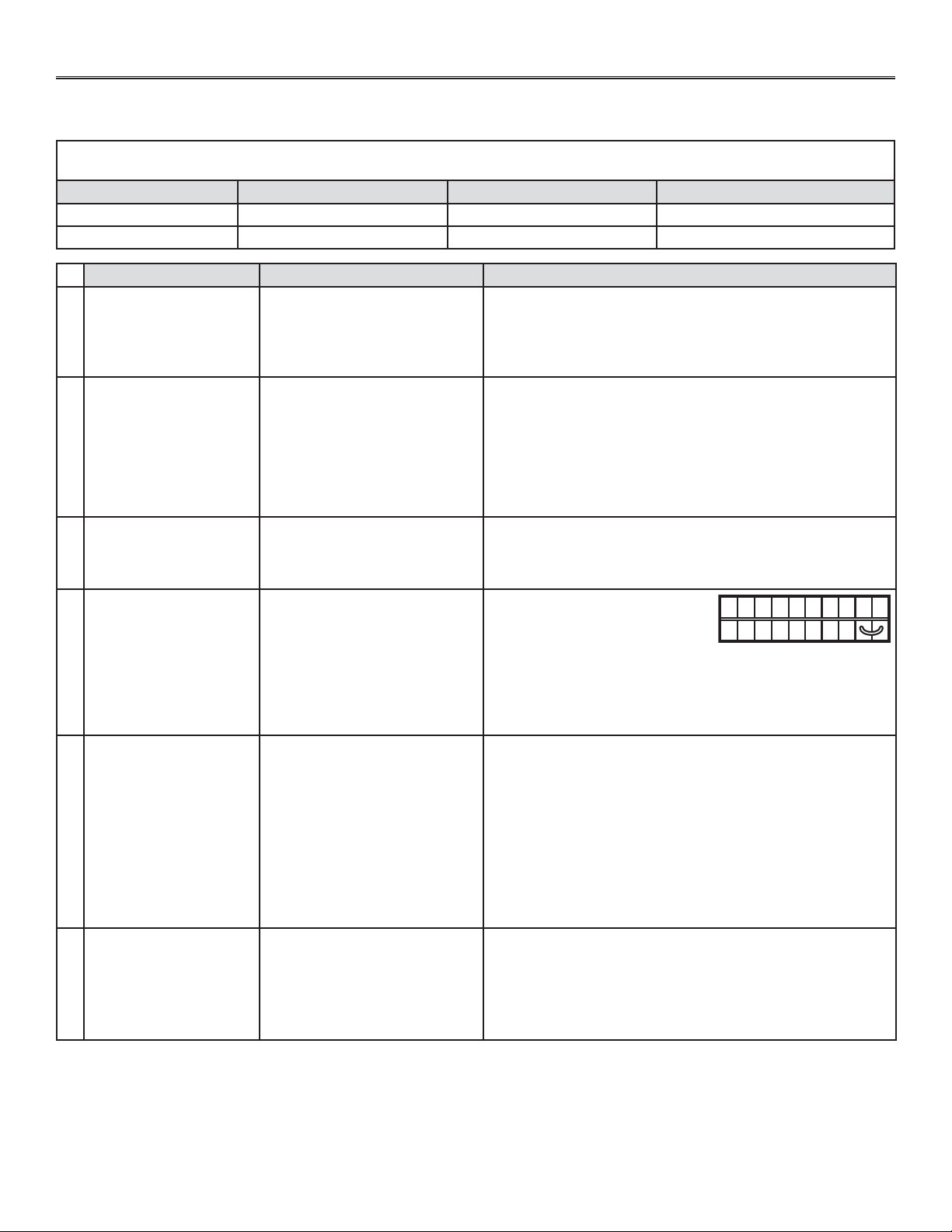
9. TROUBLESHOOTING
If the unit does not work properly, reset the unit by unplugging it for one minute and then replug it. If it is still not working
properly, refer to table below.
If the integrated control LED of the unit is flashing, this means the unit sensors detected a problem. See the table below to know where
the problem occurs on the unit.
LED COLOR ERROR TYPE ACTION UNIT STATUS
LED flashes GREEN Thermistor error Replace thermistor Unit works but will defrost frequently
LED flashes AMBER Damper error Go to point 5 Unit does not work
• Unplug the unit. Disconnect the
main control and the optional
auxiliary control(s) (if need be).
Jump G and B terminals. Plug the
unit back and wait about 10 seconds. If the motors run on high
speed and the damper opens, the circuit board is not defective.
• Check if fuse F1 is blown. In that case, replace fuse F1 as per
product nameplate.
NO C NC I OC OL Y R G B
VE0097
PROBLEMS POSSIBLE CAUSES YOU SOULD TRY THIS
1
The error code E1 is
displayed on VT8W or
VT7W wall control screen.
• The wires may be in reverse
position.
• The wires may be broken.
• The wires may have a bad
connection.
• Ensure that the color coded wires have been connected to their
appropriate places.
• Inspect every wire and replace any that is damaged.
• Ensure the wires are correctly connected.
2
There is no outdoor
temperature displayed on
VT8W wall control screen
__.
• The unit thermistor is defective
(the integrated control LED of
the unit must flash GREEN).
NOTE: At its very start-up or after a power failure, it takes some
minutes before the outdoor temperature appears on
screen. The delay duration depends on which operation
mode the wall control is set. The shortest delay is obtained
when the wall control is set on MIN or MAX in VENT Mode.
• Replace the unit thermistor.
3
VT8W or VT7W wall
control screen alternates
between normal display
and E3.
• The VT8W or VT7W wall control
may be defective.
• Replace the VT8W or VT7W wall control.
4
Unit does not work. • The circuit board
may be defective.
• The fuse may be defective.
5
The damper actuator
does not work.
• The damper actuator or the
integrated damper mechanism
may be defective.
• The circuit board or the
transformer may be defective.
• Unplug the unit. Disconnect the main control and the optional
controls(s) (if need be). Wait 10 seconds and plug the unit back.
Check if the damper opens. If not, use a multimeter and check
for 24 VAC on J12-1 and J12-2 (in electrical compartment). If
there is 24 VAC, replace the entire damper assembly.
NOTE: It is normal to experience a small delay (7-8 seconds)
before detecting the 24 VAC signal at starting-up. This
signal will stay during 17-18 seconds before disappearing.
• If there is no 24 VAC, check for 24 VAC between J8-1 and J8-2.
If there is 24 VAC, replace the circuit board, and if there is no 24
VAC, change the transformer.
6
The wall control does not
work.
• The wires may be in reverse
position.
• The wires may be broken.
• The wire in the wall OR the wall
control may be defective.
• Ensure that the color coded wires have been connected to their
appropriate places.
• Inspect every wire and replace any that are damaged.
• Remove the wall control and test it right beside the unit using
another shorter wire. If the wall control works there, change the
wire. If it does not, change the wall control.
20
9. TROUBLESHOOTING (CONT’D)
PROBLEMS POSSIBLE CAUSES YOU SOULD TRY THIS
7
The VB60W push button
timer does not work OR
its indicator light does not
stay on.
• The wires may be in reverse
postion.
• The VB60W button may be
defective.
8
The motor does not work. • The fuse may be defective.
• The motor may be defective.
• The motor or capacitor
may be defective.
• Check if fuse F1 is blown. In that case, replace fuse F1 as per
product nameplate.
NOTE: Refer to Section 6 Wiring diagram.
• If the voltage reading is 120 VAC on J4, change the defective
motor.
• Using a multimeter, check the ohms value on motor connector.
For BLUE and BLACK motor wires, the right value is ± 43 ohms.
For BLUE and BROWN motor wires, the right value is ± 48
ohms. For BROWN and BLACK motor wires, the right value is
± 91 ohms. If the ohms values are the same, the motor is not
defective. Replace the motor capacitor.
9
The defrost cycle does
not work (the fresh air
duct is frozen) OR the
fresh air distributed is very
cold.
• Ice deposits may be hindering
the damper operation.
• The damper rod or the port
damper itself may be broken.
• The damper actuator or circuit
board may be defective.
• Remove the ice.
• Inspect these parts and replace if necessary.
• See point 5.
10
The integrated defrost
control push button does
not work.
• The 30-second boot sequence
is not completed.
• See Section 4.1 Booting Sequence.
• Ensure that the color coded wires have been connected to their
appropriate places.
• Jump the OL and OC terminals.
If the unit switch to high speed,
remove the VB60W push button
and test it right beside the unit
using another shorter wire. If it works here, change the wire. If it
doesn’t, change the VB60W push button.
NO C NC I OC OL Y R G B
VE0098
If the problem is still not solved, call our Technical Support: 1-800-543-3055.
MANUAL DE INSTALACIÓN
MODELOS HRVH100S Y ERVH100S
Estos productos han sido distinguidos con el logotipo ENERGY STAR
®
al cumplir las directrices de eficiencia energética
establecidas por el Ministerio de Recursos Naturales de Canadá y la Agencia Federal de Protección Ambiental (EPA) de
Estados Unidos. Los productos cumplen las exigencias del programa ENERGY STAR únicamente cuando se emplean
en Canadá.
SÓLO PARA USO RESIDENCIAL INTERIOR
! !
LEA Y CONSERVE ESTAS INSTRUCCIONES
22734 rev. 03
VB0235
Broan-NuTone LLC; Hartford, Wisconsin www.broan.com 1-800-543-3055
REGISTRE SU PRODUCTO EN LÍNEA EN: www.broan.com/register
Para obtener más información, visitar nuestro sitio www.broan.com
2
Con el fin de hacer hincapié en determinada información, en este manual se emplean los siguientes símbolos:
Se refiere a una instrucción que, de no seguirse, podría causar daños corporales e incluso la muerte.
Se refiere a una instrucción que, de no seguirse, podría dañar gravemente el aparato o sus componentes.
NOTA: indica una información complementaria que es necesaria para completar totalmente una instrucción.
ADVERTENCIA
!
PRECAUCIÓN
OBSERVACIONES SOBRE ESTOS APARATOS
LÍMITES
Sólo para instalaciones residenciales. El trabajo de instalación y el cableado eléctrico han de ser efectuados por personal cualificado
conforme a todos los códigos y normas aplicables, incluso los relativos a lugares con alto riesgo de incendio.
ADVERTENCIA
!
PARA REDUCIR EL RIESGO DE INCENDIO, CHOQUE ELÉCTRICO O HERIDAS CORPORALES, SIGA LAS INDICACIONES
SIGUIENTES:
1. Utilice el aparato únicamente de la manera prevista por el fabricante. Si tiene preguntas, póngase en contacto con el fabricante en la
dirección o en el teléfono que aparecen en la garantía.
2. Le aconsejamos que un técnico especializado examine el aparato una vez al año.
3. Antes de realizar tareas de mantenimiento o de limpiar el aparato desenchufe el cable de alimentación de la toma eléctrica.
4. Este aparato no ha sido pensado para la combustión ni para el aire de dilución de aparatos que queman combustible.
5. Al cortar o taladrar en la pared o en el techo, procure no dañar el cableado eléctrico ni otras instalaciones ocultas.
6. No utilice este aparato con un dispositivo de control de velocidad con semiconductores distintos de los controles de pared opcionales
principales y auxiliares siguiente:
7. El aparato debe conectarse a tierra. El cable de alimentación lleva un enchufe con toma de tierra de 3 patillas para su seguridad
personal. Debe enchufarse en una toma de corriente para tres patillas, conectada a tierra de acuerdo con el código eléctrico nacional
y los códigos y ordenanzas locales. No retire la patilla de la toma de tierra. No utilice el aparato con un cable prolongador.
8. No instale el aparato en un espacio donde se cocina ni lo conecte directamente a otro aparato.
9. No lo use para evacuar materias ni vapores peligrosos o explosivos.
10. Para la instalación, el mantenimiento o la limpieza del aparato se aconseja llevar lentes y guantes de seguridad.
11. Dado el peso del aparato, se aconseja dos personas para la instalación.
12. Cuando la reglamentación local aplicable sea más restrictiva en materia de instalación o certificación, dicha reglamentación prevalecerá
sobre las exigencias de este manual y el instalador acepta atenerse a dicha reglamentación y asumir los gastos correspondientes.
PRECAUCIÓN
1. Para evitar que los filtros se obstruyan prematuramente, apague el aparato durante las obras de construcción o renovación.
2. Para mayor información sobre otras exigencias, lea la etiqueta de especificaciones que viene en el aparato.
3. Conecte los tubos de aire con el exterior. No tome ni evacue el aire en espacios situados entre paredes, en el techo o en un desván,
en sótanos pequeños ni en cocheras.
4. Aparato para instalación residencial únicamente, de acuerdo con las exigencias de la norma 90B de la NFPA.
5. No instale ningún tubo de aire directamente encima o a menos de 2 pies de un horno, de su cámara impelente, de una caldera o de
otro aparato que genere calor. Si hay que conectar un tubo a la cámara de retorno de una caldera, debe situarse al menos a 9’ y 10”
de la conexión de la cámara con la caldera.
6. Los tubos deben instalarse de acuerdo con todos los códigos aplicables.
7. Al ausentarse de la vivienda durante un periodo largo (más de dos semanas), una persona responsable debería verificar regularmente
si el aparato funciona correctamente.
8. Si los tubos pasan a través de un espacio no acondicionado (como un desván), el aparato debe funcionar constantemente, excepto
cuando haya que hacer tareas de mantenimiento o reparaciones. Asimismo, la temperatura ambiente de la casa nunca debería bajar
de 65°F.
Controles de pared opcionales principales Controles de pared opcionales auxiliares
VT8W, VT7W, VT4W y VT6W 59W y VB60W
ACERCA DE ESTE MANUAL

ÍNDICE
3
1. D IMENSIONES . . . . . . . . . . . . . . . . . . . . . . . . . . . . . . . . . . . . . . . . . . . . . . . . . . 3
2. INSTALACIÓNES HABITUALES . . . . . . . . . . . . . . . . . . . . . . . . . . . . . . . . . . . . . . . . . . . . 4
2.1 SISTEMA TOTALMENTE EQUIPADO CON TUBOS . . . . . . . . . . . . . . . . . . . . . . . . . . . . . . . . . . . . . . 4
2.2 VENTILACIÓN EN EL PUNTO DE ORIGEN . . . . . . . . . . . . . . . . . . . . . . . . . . . . . . . . . . . . . . . . . 4
2.3 INSTALACIÓN SIMPLIFICADA . . . . . . . . . . . . . . . . . . . . . . . . . . . . . . . . . . . . . . . . . . . . . . 4
3. INSTALACIÓN . . . . . . . . . . . . . . . . . . . . . . . . . . . . . . . . . . . . . . . . . . . . . . . . 5-11
3.1 INSPECCIÓN DEL CONTENIDO DE LA CAJA . . . . . . . . . . . . . . . . . . . . . . . . . . . . . . . . . . . . . . . . 5
3.2 HERRAMIENTAS Y MATERIAL . . . . . . . . . . . . . . . . . . . . . . . . . . . . . . . . . . . . . . . . . . . . . . 6
3.3 UBICACIÓN DEL APARATO . . . . . . . . . . . . . . . . . . . . . . . . . . . . . . . . . . . . . . . . . . . . . . . 6
3.4 PLANIFICACIÓN DE LAS TUBERÍAS . . . . . . . . . . . . . . . . . . . . . . . . . . . . . . . . . . . . . . . . . . . . 6
3.5 INSTALACIÓN DE TUBOS Y DIFUSORES NO AISLADOS . . . . . . . . . . . . . . . . . . . . . . . . . . . . . . . . . . . 7-9
3.5.1 SISTEMA TOTALMENTE EQUIPADO CON TUBOS . . . . . . . . . . . . . . . . . . . . . . . . . . . . . . . . . . . . . . . . . 7
3.5.2 VENTILACIÓN EN EL PUNTO DE ORIGEN . . . . . . . . . . . . . . . . . . . . . . . . . . . . . . . . . . . . . . . . . . . . 8
3.5.3 INSTALACIÓN SIMPLIFICADA . . . . . . . . . . . . . . . . . . . . . . . . . . . . . . . . . . . . . . . . . . . . . . . . . 9
3.6 INSTALACIÓN DE TUBOS FLEXIBLES AISLADOS. . . . . . . . . . . . . . . . . . . . . . . . . . . . . . . . . . . . . . 10
3.6.1 CONEXIÓN CON LAS BOCAS DEL APARATO. . . . . . . . . . . . . . . . . . . . . . . . . . . . . . . . . . . . . . . . . . .10
3.6.2 UBICACIÓN DE LAS BOCAS EXTERIORES . . . . . . . . . . . . . . . . . . . . . . . . . . . . . . . . . . . . . . . . . . .10
3.7 CONEXIÓN DE LOS TUBOS AISLADOS A LAS BOCAS EXTERIORES . . . . . . . . . . . . . . . . . . . . . . . . . . . . . 11
3.8 INSTALACIÓN DEL CONJUNTO DE CAMBIO DE SECCIÓN TANDEM
®
. . . . . . . . . . . . . . . . . . . . . . . . . . . . . 11
3.9 CONEXIÓN DEL DESAGÜE . . . . . . . . . . . . . . . . . . . . . . . . . . . . . . . . . . . . . . . . . . . . . . 11
4. CONTROLES. . . . . . . . . . . . . . . . . . . . . . . . . . . . . . . . . . . . . . . . . . . . . . . . . 12-14
4.1 CONTROL INTEGRADO. . . . . . . . . . . . . . . . . . . . . . . . . . . . . . . . . . . . . . . . . . . . . . . . 12
4.2 SECUENCIA DE PUESTA EN MARCHA. . . . . . . . . . . . . . . . . . . . . . . . . . . . . . . . . . . . . . . . . . 12
4.3 CONFIGURACIÓN DE LA DESCONGELACIÓN AMPLIADA . . . . . . . . . . . . . . . . . . . . . . . . . . . . . . . . . . 12
4.4 CONEXIÓN ELÉCTRICA CON LOS CONTROLES DE PARED . . . . . . . . . . . . . . . . . . . . . . . . . . . . . . . .13-14
4.4.1 CONEXIÓN ELÉCTRICA CON UN CONTROL DE PARED PRINCIPAL VT8W . . . . . . . . . . . . . . . . . . . . . . . . . . . . . .13
4.4.2 CONEXIÓN ELÉCTRICA CON UN CONTROL DE PARED PRINCIPAL VT7W . . . . . . . . . . . . . . . . . . . . . . . . . . . . . .13
4.4.3 CONEXIÓN ELÉCTRICA CON UN CONTROL DE PARED PRINCIPAL VT4W . . . . . . . . . . . . . . . . . . . . . . . . . . . . . .13
4.4.4 CONEXIÓN ELÉCTRICA CON UN CONTROL DE PARED PRINCIPAL VT6W . . . . . . . . . . . . . . . . . . . . . . . . . . . . . .13
4.4.5 CONEXIÓN ELÉCTRICA CON LOS CONTROLES DE PARED AUXILIARES OPCIONALES. . . . . . . . . . . . . . . . . . . . . . . . . .14
5. CONEXIÓN ELÉCTRICA CON LA CALDERA . . . . . . . . . . . . . . . . . . . . . . . . . . . . . . . . . . . . . 15
6. DIAGRAMA DE CABLEADOS . . . . . . . . . . . . . . . . . . . . . . . . . . . . . . . . . . . . . . . . . . . 16
7. E QUILIBRADO DEL APARATO . . . . . . . . . . . . . . . . . . . . . . . . . . . . . . . . . . . . . . . . . . . 17
8. PIEZAS DE RECAMBIO. . . . . . . . . . . . . . . . . . . . . . . . . . . . . . . . . . . . . . . . . . . . . . 18
9. SOLUCIÓN DE PROBLEMAS . . . . . . . . . . . . . . . . . . . . . . . . . . . . . . . . . . . . . . . . . .19-20
1. DIMENSIONES
11¼ "
17
7
/16"
37
7
/8"
33"
11
7
/8"
VK0086A
39 /8"
4
2. INSTALACIONES HABITUALES
Utilice las ilustraciones siguientes como referencia para elegir la forma de instalar el aparato.
Todos los aparatos deberían colgarse de vigas.
En todos los casos se podría utilizar ventiladores del cuarto de baño o una campana de cocina para sacar el aire viciado. Asimismo, en
las viviendas de más de un nivel aconsejamos un registro de salida en el nivel superior.
Hay 3 métodos de instalación: sistema totalmente equipado con tubos, ventilación en el punto de origen e instalación simplificada.
NOTA: ha de haber una toma eléctrica disponible a menos de 3 pies del aparato.
2.1 SISTEMA TOTALMENTE EQUIPADO CON TUBOS (PRICIPALMENTE PARA VIVIENDAS CON CALEFACCIÓN POR AGUA CALIENTE RADIANTE O POR
RADIATORES ELÉCTRICOS)
VH0024
El aire viciado proveniente del registro situado en el nivel superior de
la vivienda se extrae al exterior. El aire fresco del exterior se filtra y se
introduce por el registro situado en el nivel habitable inferior.
Las viviendas con más de un nivel necesitan al menos un registro de
salida en el nivel superior.
Véase la ilustración de la derecha.
2.2 VENTILACIÓN EN EL PUNTO DE ORIGEN (CONEXIÓN CON UN SISTEMA DE AIRE FORZADO)
VH0025
El aire viciado proveniente del registro situado en el nivel superior de
la vivienda se extrae al exterior. El aire fresco del exterior se filtra y se
introduce por el conducto de retorno (cámara) o de alimentación del
aparato de aire forzado.
Véase la ilustración de la derecha.
Para este tipo de instalación no es esencial que el ventilador impelente
del sistema de aire forzado funcione cuando el aparato esté funcionando,
pero es aconsejable.
NOTA: las viviendas con varios sistemas de aire forzado deberían
contar con un aparato para cada sistema.
2.3 INSTALACIÓN SIMPLIFICADA (CONEXIÓN CON UN SISTEMA DE AIRE FORZADO)
VH0093
El aire viciado se extrae al exterior. El aire fresco del exterior se filtra y
se introduce por el conducto de retorno (cámara) o de alimentación del
aparato de aire forzado.
Véase la ilustración de la derecha.
Para evitar la contaminación cruzada y lograr la máxima eficacia, el
ventilador impelente del sistema de aire forzado debe estar encendido
siempre.
NOTA: las viviendas con varios sistemas de aire forzado deberían
contar con un aparato para cada sistema.
5
3. INSTALACIÓN
• Examine el exterior del aparato para ver si ha sufrido daños durante el transporte. Compruebe que la puerta, las bocas, el
cable de alimentación, etc. no estén dañados
• Retire la cinta de transporte del núcleo de recuperación de calor
o energía del aparato.
• Examine el interior del aparato para ver si ha sufrido daños.
Compruebe que el conjunto del ventilador, el núcleo de
recuperación de calor o energía, los filtros del núcleo, el aislante,
los registros, el prefiltro y el filtro HEPA, etc. estén intactos. Vuelva
a instalar la puerta
NOTA: escriba la fecha de instalación en el marco del filtro HEPA
para futuras consultas (véase la ilustración de la derecha).
TOP
DESSUS
FRONT
AVANT
Instal. date:
Date d’instal. :
__ / __ / ____
21293
FRONT
AVANT
Instal. date:
Date d’instal. :
__ / __ / ____
VD0322
NOTA: antes de empezar con la instalación, verifique el contenido de la caja. Retire todo el material de embalaje del aparato
Para que no se dañen los enganches de la puerta, no la abra completamente.
Inclínela unas 3 pulgadas desde la base del aparato y levántela. Véase la
ilustración de abajo.
PRECAUCIÓN
±3”
VD0303A
B
C
VD0302
A
• Utilice un destornillador Phillips o Robertson para desatornillar los tornillos (A)
de la puerta.
NOTA: los tornillos seguirán sujetos a la puerta.
• Abra (B) y levante (C) la puerta.
3.1 INSPECCIÓN DEL CONTENIDO DE LA CAJA
6
3. INSTALACIÓN (CONTINUACIÓN)
3.3 UBICACIÓN DEL APARATO
Elija la ubicación apropiada para el aparato.
• En una zona de la vivienda donde la temperatura ambiente se mantenga entre 50°F y 104°F.
• Lejos de las zonas habitables (comedor, sala de estar, dormitorio) de ser posible.
• El acceso al interior del aparato para tareas de mantenimiento debe ser fácil.
• Cerca de una pared exterior para limitar la longitud del tubo flexible aislado que sale del aparato o llega a él.
• Lejos de chimeneas calientes y otros lugares que presenten peligro de incendio.
• Prevea una fuente de alimentación (toma de corriente para enchufes de tres patillas con conexión a tierra).
• SÓLO PARA LOS APARATOS HRV: cerca de un desagüe. Si no hay desagüe
cerca, utilice un balde para recoger los residuos líquidos.
Cuelgue el aparato con los cuatro ganchos, cadenas y muelles provistos. Vea la
ilustración de la derecha.
VD0305
Procure que el aparato esté a nivel.
PRECAUCIÓN
3.2 HERRAMIENTAS Y MATERIAL
Estas son las herramientas y el material necesarios para la instalación:
• Destornillador Phillips n.° 2 o destornillador Robertson n.° 2
• Destornillador pequeño de punta plana (para conectar el control mural)
• Desforrador de hilos (para conectar el control mural)
• Martillo y destornillador de punta plana (sólo para la instalación de la conexión de la cámara, para hacer agujeros en el tubo
metálico existente)
• Tijeras o cuchilla (para cortar la cinta adhesiva para tubos)
• Cinta métrica
• Cinta adhesiva para tubos
• Tijeras de hojalatero o cizalla (sólo para la instalación de la conexión de la cámara, para cortar tubos)
• Cinta adhesiva de aluminio para tubos (sólo para la instalación de la conexión de la cámara)
• Sierra de corte vertical
• Material sellante para calafateo y pistola para calafateo.
3.4 PLANIFICACIÓN DE LAS TUBERÍAS
• Evite complicaciones. Planifique la instalación de forma que haya el menor número posible de ángulos y juntas.
• Reduzca al mínimo la longitud de los tubos aislados.
• No ventile sótanos pequeños ni cámaras frigoríficas. No intente recuperar el aire de salida de una secadora o de una
campana ya que podrían obstruirse los filtros y el módulo de recuperación.
• Si la vivienda tiene dos o más plantas, prevea al menos un registro de salida en el nivel habitable superior.
7
CÓMO CONECTAR LOS TUBOS FLEXIBLES A LOS DIFUSORES
Una vez decidida la ubicación de los difusores, corte un agujero de 5¼” de diámetro.
Pase un extremo del tubo flexible por el agujero y sujételo a la base del difusor (1)
utilizando para ello una cinta de amarre y cinta adhesiva para tubos. Instale la base
del difusor en la pared (o el techo) con los 4 tornillos 8 x 3/4”. A continuación, ponga
el difusor (2).
Vea la ilustración de la derecha.
Ø 5¼”
VJ0094A
2
1
3. INSTALACIÓN (CONTINUACIÓN)
CÓMO CONECTAR LOS TUBOS FLEXIBLES A LAS BOCAS DEL APARATO
Los dos tubos flexibles conectados a los difusores deben conectarse a las bocas
inferiores del aparato. Si se sitúa delante de la puerta del aparato, la boca de aire
fresco hacia el interior es la que está a la izquierda y la boca de aire de salida desde
el interior es la que está a la derecha. Utilice una cinta de amarre para sujetar el tubo
de aire fresco hacia el interior a su boca correspondiente. A continuación, haga lo
miso con el tubo y la boca de aire de salida hacia el interior. Vea la ilustración de la
derecha.
NOTA: use un tubo aislado si el tubo tiene que pasar por un espacio donde se
pueden dar temperaturas extremas (en regiones nórdicas, en un desván
sin calefacción en invierno o un desván no refrigerado en regiones cálidas).
Asimismo, si prevé que el aparato no funcionará durante más de 12 horas,
aconsejamos cubrir el tubo con aislante R12.
VJ0107
Aire de salida desde el interior
LADO DERECHO DEL APARATO
Tubos de distribución de aire fresco
• Instale el difusor de distribución de aire fresco en una zona amplia y abierta en el nivel más bajo para permitir la mayor cir-
culación de aire posible.
• Tenga en cuenta que el difusor de aire fresco debe estar situado lo más lejos posible del difusor de aire viciado. Si desea,
puede instalar otro difusor.
• Instale el difusor en el techo O a una distancia de 6 a 12 pulgadas del techo en una pared interior (el aire más frío cruzará la
parte superior de la habitación y se mezclará con el aire de ésta antes de descender a la altura del ocupante).
• Si hay que instalar un registro en el suelo, dirija la circulación del aire hacia la pared.
IDENTIFICACIÓN DE LAS BOCAS DEL APARATO
Cada boca del aparato tiene una etiqueta
de identificación al lado para evitar
conexiones erróneas. Consulte siempre
las etiquetas antes de conectar cualquier
tubo y boca.
VJ0106
Aire de salida hacia el exterior
Aire fresco hacia el interior
Aire fresco desde el exterior
Aire de salida desde el interior
PUERTA
DEL
APARATO
Tubos de salida de aire viciado
• Instale el difusor de salida de aire viciado en la zona donde se produzcan principalmente los contaminantes: cocina, sala de
estar, etc. Sitúe el difusor lo más lejos posible de las escaleras de manera que el aire circule en todos los espacios habitables
de la vivienda.
• Si se instala un difusor en la cocina, debe situarse al menos a 4 pies del aparato para cocinar.
• Instale el difusor a una distancia de 6 a 12 pulgadas del techo en una pared interior O en el techo.
No instale nunca un difusor de salida de aire viciado en una habitación cerrada en la que funcione un dispositivo
de combustión, como un aparato de calefacción de gas, un calentador de agua de gas o una chimenea.
ADVERTENCIA
!
3.5 INSTALACIÓN DE TUBOS Y DIFUSORES NO AISLADOS
3.5.1 SISTEMA TOTALMENTE EQUIPADO CON TUBOS (ILUSTRACIÓN EN LA SECCIÓN 2.1)

8
3.5 INSTALACIÓN DE TUBOS Y DIFUSORES NO AISLADOS (CONTINUACIÓN)
3. INSTALACIÓN (CONTINUACIÓN)
Tubos de salida de aire viciado
Igual que para el sistema totalmente equipado con tubos descrito en la etapa 3.5.1
3.5.2 VENTILACIÓN EN EL PUNTO DE ORIGEN (ILUSTRACIÓN EN LA SECCIÓN 2.2)
Tubos de distribución de aire fresco
Al conectar los tubos, use siempre herramientas y material aprobado. Cumpla con todas las leyes y
reglamentos de seguridad correspondientes. Consulte el código de construcción local.
ADVERTENCIA
!
Método 2: Conexión por el lado de retorno
• Sitúe la abertura para el tubo de aire fresco en el tubo de retorno del aparato de
aire forzado a una distancia en línea mínima de 9’ 10” en sentido ascendente
(desde el punto de descenso del aparato de aire forzado: A+B+C). Corte un
agujero de 5” de diámetro en ese lugar con una cizalla.
• Utilice un cambio de sección metálico (no incluido; adquiéralo en una ferretería)
para conectar el tubo del aparato al tubo de retorno del aparato de aire forzado.
• Sujete el otro extremo del tubo flexible a la boca de aire fresco hacia
el interior (véase el icono en el lado izquierdo del aparato). Utilice una
cinta de amarre y cinta adhesiva para tubos para sellar la conexión.
Vea la ilustración de la derecha.
VJ0099
A + B + C = NO MENOS
DE 9’ 10”
PUERTA DEL
APARATO
CAMBIO DE
SECCIÓN METÁLICO
Al conectar un tubo al tubo de alimentación de un aparato de aire forzado, el tamaño de este tubo debe
adaptarse para soportar la corriente de aire adicional que produce el HRV o el ERV. Asimismo, use un
tubo metálico con un registro contracorriente para evitar el riesgo de recalentamiento de los aparatos
HRV/ERV.
PRECAUCIÓN
Hay dos métodos para conectar el aparato a el aparato de aire forzado:
Método 1: Conexión por el lado de la alimentación
• Corte una apertura en el tubo de alimentación del aparato de aire
forzado al menos a 18 pulgadas del aparato de aire forzado.
• Conecte esta apertura a la boca de Aire fresco hacia el interior del
aparato HRV o ERV (use un tubo metálico vea la ilustración de la
derecha).
• Compruebe que el tubo del aparato HRV o ERV forma un codo dentro
del tubo del aparato de aire forzado.
• Si desea, interbloquee (sincronice) el funcionamiento del ventilador
impelente del aparato de aire forzado con el funcionamiento del aparato
HRV o ERV (véase la sección 5).
VJ0108
MíNIMO 18”
PUERTA DEL
APARATO
TUBO METÁLICO CON
REGISTRO CONTRACORRIENTE
9
3.5 INSTALACIÓN DE TUBOS Y DIFUSORES NO AISLADOS (CONTINUACIÓN)
Tubo de distribución de aire fresco (conexión por el lado del retorno)
Igual que para la ventilación en el punto de origen descrita en la etapa 3.5.2.
3.5.3 INSTALACIÓN SIMPLIFICADA (ILUSTRACIÓN EN LA SECCIÓN 2.3)
Tubo de salida de aire viciado (conexión por el lado del retorno)
Al conectar los tubos, use siempre herramientas y material aprobado. Cumpla con todas las leyes y
reglamentos de seguridad correspondientes. Consulte el código de construcción local.
ADVERTENCIA
!
3. INSTALACIÓN (CONTINUACIÓN)
Al conectar un tubo al tubo de alimentación de un aparato de aire forzado, el tamaño de este tubo debe
adaptarse para soportar la corriente de aire adicional que produce el HRV o el ERV. Asimismo, use un
tubo metálico con un registro contracorriente para evitar el riesgo de recalentamiento de los aparatos
HRV/ERV.
PRECAUCIÓN
¡ Si se utiliza el método 2, compruebe que el funcionamiento del ventilador impelente del aparato de aire
forzado está sincronizado con el del aparato HRV o ERV! Véase la sección 5.
PRECAUCIÓN
VJ0109
MíNIMO 3’
PUERTA DEL
APARATO
A + B + C = NO MENOS
DE 9’ 10”
Hay dos métodos para conectar el aparato a el aparato de aire forzado:
Método 1: Conexión Retorno-alimentación Método 2: Conexión Retorno-retorno
VJ0110
MíNIMO 18”
PUERTA DEL
APARATO
A + B + C = NO MENOS
DE 9’ 10”
Admisión de aire viciado:
• Corte una apertura en el tubo de retorno del aparato de aire forzado a no menos de 9’ 10” del aparato de aire
forzado: (A+B+C).
• Conecte esta abertura a la boca de aire de salida desde el interior del aparato HRV o ERV.
Distribución del aire puro: (las instrucciones son las mismas que para el método 1 o método 2, section 3.5.2)
Para el método 2 (retorno-retorno), compruebe que hay una distancia de al menos 3 pies entre las 2 conexiones con el aparato
de aire forzado.
NOTA: Para el método 1, no es esencial sincronizar el funcionamiento del ventilador impelente del aparato de aire forzado con
el aparato HRV o ERV, pero se aconseja.
TUBO METÁLICO CON
REGISTRO CONTRACORRIENTE

10
3. INSTALACIÓN (CONTINUACIÓN)
3.6 INSTALACIÓN DE TUBOS FLEXIBLES AISLADOS
Procure que la película impermeable al vapor de los tubos aislados no se rompa durante la instalación
para evitar que se forme condensación en los tubos.
PRECAUCIÓN
Siga este procedimiento para conectar los tubos flexibles aislados a las bocas del aparato (aire de salida hacia el exterior y aire
fresco desde el exterior). Consulte las etiquetas de identificación antes de conectar cualquier tubo o boca.
Para ambos tubos restantes, retire el aislante para dejar
expuesto el tubo flexible interior.
Conecte el tubo flexible interior a la parte más pequeña
del anillo interior de la boca usando para ello una cinta de
amarre.
Pase el aislante por encima de la junta y métalo entre
el anillo interior y el exterior de la boca. Pase la película
impermeable al vapor por encima del aislante y del anillo
exterior de la boca.
Ponga cuidadosamente cinta adhesiva para tubos en
la junta para hacer un cierre hermético. Véanse las
ilustraciones de la derecha.
3.6.1 CONEXIÓN CON LAS BOCAS DEL APARATO
VJ0102
Evite comprimir el aislante al darle vueltas a la cinta adhesiva alrededor de la junta. El aislante comprimido
pierde sus propiedades y hace que el agua gotee debido a la condensación en la superficie exterior del
tubo.
PRECAUCIÓN
Elija un lugar apropiado para instalar las bocas exteriores:
• Debe haber una distancia mínima de 6’ entre las bocas exteriores para evitar la contaminación cruzada
• Debe haber una distancia mínima de 18” desde el suelo
3.6.2 UBICACIÓN DE LAS BOCAS EXTERIORES
La boca de aire fresco debe estar, como
mínimo, a una distancia de 6 pies (o
más, según los códigos o normas de
construcción aplicables) de fuentes de
contaminación como:
• Salida de secadora, de caldera de alto
rendimiento, de aspirador central
• Salida de contador de gas, barbacoa de
gas
• Cubo o contenedor de basura
• Cualquier salida de una fuente de
combustión.
ADVERTENCIA
!
VD0203
6’
6’
SALIDA DE
AIRE VICIADO
18’’
18’’
5’’ Ø
18’’
BOCA DE
AIRE FRESCO
UBICACIóN
OPCIONAL
3.7 CONEXIÓN DE LOS TUBOS AISLADOS A LAS BOCAS EXTERIORES
• Corte un agujero de 5” de diámetro en la pared exterior para cada boca
exterior. Utilice para ello una sierra de corte vertical.
• Desde fuera, coloque la boca exterior en su lugar y sujétela a la pared
exterior con 2 tornillos n.° 8 x 1½” provistos. Selle el borde con silicona.
• Desde la parte interior retire el aislante para dejar al descubierto el
tubo flexible y sujete éste al tubo rígido de la boca exterior por medio
de una cinta de amarre. Obture la junta cuidadosamente con cinta
adhesiva para tubos. Pase la película impermeable al vapor por encima
del aislante y de la junta. Ponga cuidadosamente cinta adhesiva para
tubos en la junta para hacer un cierre hermético. Véase la ilustración
de la derecha.
VR0028
3. INSTALACIÓN (CONTINUACIÓN)
11
3.8 INSTALACIÓN DEL CONJUNTO DE CAMBIO DE SECCIÓN* TANDEM
®
Si se desea, puede realizarse la conexión de los tubos aislados con el exterior
con el conjunto de cambio de sección Tandem (debe adquirirse aparte;
n.° de pieza VTYIK1). La abertura de la viga necesaria para instalar el cambio de
sección Tandem debe ser de 9¾” como mínimo. La altura máxima del cambio de
sección Tandem es de 8¾”. Para conectar los tubos flexibles aislados al cambio de
sección Tandem (aire de salida hacia el exterior y aire fresco desde el exterior),
siga las instrucciones que vienen con el conjunto de cambio de sección.
*Patentado.
VR0003
Conjunto de cambio
de sección* Tandem
®
3.9 CONEXIÓN DEL DESAGÜE
Corte dos secciones del tubo de plástico —de una longitud de 12”
aproximadamente— y conecte cada una de ellas con los desagües
interiores situados debajo del aparato como se ve en la ilustración.
Una ambas secciones al empalme en ‘T’ y al tubo principal, como
se ve en la ilustración, para evitar que el aparato emita olores
desagradables por el desagüe.
VD0308A
± 1”
Lleve el tubo al desagüe del suelo, a otro tubo de
desagüe o a un balde.
IMPORTANTE
Si utiliza un balde para recoger el agua, sitúe el
extremo del tubo a 1” aproximadamente de la
parte superior del balde para evitar que el agua
retroceda al aparato.
VD0311E
± 12”
± 12”
CINTA DE
AMARRE
NOTAS: 1. Para el aparato ERV, retire los tapones de desagüe que hay
dentro del aparato antes de instalar los tubos.
2. El conjunto del núcleo y del ventilador del aparato ERV no
aparece en la ilustración para que pueda comprenderse mejor.
VD0323
Para todos los aparatos HRV debe instalare un tubo de desagüe (incluido). Para los aparatos ERV no es
necesario aunque se aconseja en climas en los que la temperatura exterior normalmente si sitúa por
debajo de -13°F durante un periodo de 24 horas durante varios días seguidos y la humedad interior es
del 40% o más.
PRECAUCIÓN
12
4. CONTROLES
4.2 SECUENCIA DE PUESTA EN MARCHA
La secuencia de puesta en marcha del aparato es similar a la de una computadora personal. Cada vez que se enchufa el aparato
tras haberse desenchufado o tras una interrupción de la alimentación eléctrica, el aparato inicia la secuencia de puesta en marcha
de unos 30 segundos antes de empezar a funcionar.
Durante la secuencia de puesta en marcha, el diodo electroluminiscente (LED) del control integrado se encenderá de color ÁMBAR
durante 5 segundos y luego se apagará durante 2 segundos. A continuación, el diodo se encenderá en ROJO durante el resto de la
secuencia de puesta en marcha. Mientras el diodo está en ROJO, el aparato verifica y reconfigura la posición del registro motorizado.
Una vez establecida la posición del registro motorizado, el diodo ROJO se apaga para indicar que la secuencia de puesta en marcha
ha terminado.
NOTA: el aparato no acepta ninguna instrucción hasta que se haya puesto en marcha totalmente.
4.3 CONFIGURACIÓN DE LA DESCONGELACIÓN AMPLIADA
Si se produjera un problema durante el funcionamiento del aparato, el diodo de control integrado (2) parpadeará. El color de la luz
depende del tipo de error detectado. Para mayor información, consulte la sección 9. Solución de problemas en la última página.
NOTA: Al utilizar el control principal opcional, el control integrado del aparato de estar apagado.
4.1 CONTROL INTEGRADO
Todos los aparatos están equipados con un control integrado situado debajo del compartimento
eléctrico. Utilice el bóton pulsador (1) para controlar el aparato. El diodo (2) le indicará el modo en el
que funciona el aparato (véase la ilustración de la derecha).
PRESIONE EL BÓTON PULSADOR COLOR DEL DIODO RESULTADOS
UNA VEZ ÁMBAR EL APARATO FUNCIONA A BAJA VELOCIDAD
DOS VECES VERDE EL APARATO FUNCIONA A ALTA VELOCIDAD
TRES VECES SIN LUZ EL APARATO ESTÁ APAGADO
1
2
VD0310
Consulte la tabla siguiente para saber cómo funciona el aparato por medio del control integrado.
La unidad está configurada de fábrica para un descongelado normal. En regiones frías (temperatura exte-
rior -17°F e inferior), puede ser necesario configurar un descongelado extendido. Durante los tres primeros
segundos de la sequencia de puesta en marcha, mientras el LED del control integrado está en ÁMBAR,
presione el botón pulsador alrededor de tres segundos. El LED parpadeará de color VERDE el número de veces
correspondientes al modo actual de descongelado de la unidad.
NOTA: Durante la configuración del descongelado extendido, mientras el botón es presionado, el LED se
encenderá de color ROJO, para indicar que la señal ha sido recibida.
Consulte la siguiente tabla para modificar el ciclo de descongelado de la unidad. Es posible cambiar la selección tantas veces como
sea necesario.
CICLO DE DESCONGELACIÓN PRESIONE SOBRE EL BOTÓN LED PARPADEARÁ VERDE
1 NORMAL (APARATO HRV) UNA VEZ 1 VEZ
2 AMPLIADA (APARATO HRV) DOS VECES 2 VECES
3 NORMAL (APARATO ERV) TRES VECES 3 VECES
4 AMPLIADA (APARATO ERV) CUATRO VECES 4 VECES
VD0324
Para salir de la configuración del descongelado extendido, presione 3 segundos sobre el botón O espere 60 segundos ; el LED
parpadeará y se apagará, entonces se encenderá de color ROJO (la unidad regresa en su secuencia de puesta en marcha).
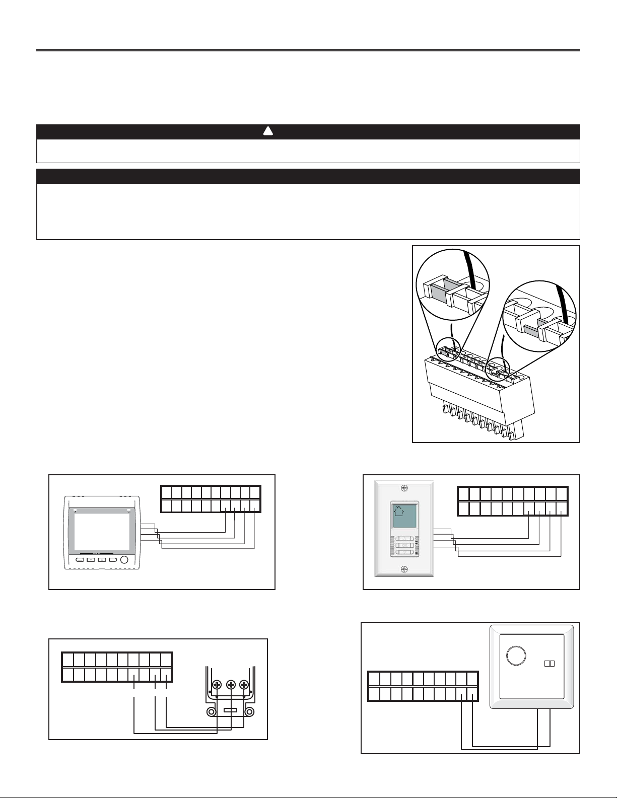
13
4. CONTROLES (CONTINUACIÓN)
4.3 CONEXIÓN ELÉCTRICA CON LOS CONTROLES DE PARED
Para mayor comodidad, este aparato también puede controlarse mediante un control de pared principal opcional.
NOTAS: 1. Al utilizar el control principal opcional, el control integrado del aparato de estar apagado.
2. Si se está utilizando un control auxiliar opcional (cuando está activado), el mando de control auxiliar prevalece sobre el
control principal opcional.
ADVERTENCIA
Desconecte siempre el aparato antes de efectuar cualquier conexión. De no desconectar la alimentación, podría
producirse un choque eléctrico o dañarse el control mural o el módulo electrónico dentro del aparato.
!
PRECAUCIÓN
No instale nuncas más de un control de pared principal por aparato. Compruebe que los cables no hagan
cortocircuito entre ellos o tocando otros componentes del control de pared. Evite las malas conexiones de los
cables. Para reducir la interferancia eléctrica (ruido) potencial, no pase los cables del control de pared cerca de
los contactores de control ni de circuitos de atenuación de la luz, motores eléctricos, alimentación de viviendas
o edificios, cables de iluminación o tableros de distribución de energía.
Use el conector de terminales incluido en el conjunto para la instalación para realizar la
conexión eléctrica del control mural principal y de los controles opcionales. Verifique si todos
los hilos han sido introducidos en los orificios correspondientes en el bloque de terminales.
(Un hilo está introducido correctamente cuando su receptáculo naranja está más bajo que
otro sin hilo. En la ilustración de la derecha, el hilo A ha sido introducido correctamente, pero
no el B
4.3.1 CONEXIÓN ELÉCTRICA CON UN CONTROL DE PARED
PRINCIPAL VT8W
4.3.2 CONEXIÓN ELÉCTRICA CON UN CONTROL DE
PARED PRINCIPAL VT7W
4.3.3 CONEXIÓN ELÉCTRICA CON UN CONTROL DE
PARED PRINCIPAL VT4W
4.3.4 CONEXIÓN ELÉCTRICA CON UN CONTROL DE
PARED PRINCIPAL VT6W
NO C NC I OC OL Y R G B
VE0181
SMART
SET
MODE
PREF
NO C NC I OC OL Y R G B
VE0250
NO C NC I OC OL Y R G B
B G
G
B
Y
VE0328A
Y
NO C NC I OC OL Y R G B
VE0187
VE0272
A
B
CONTROL DE PARED
PRINCIPAL VT4W
VISIóN TRASERA
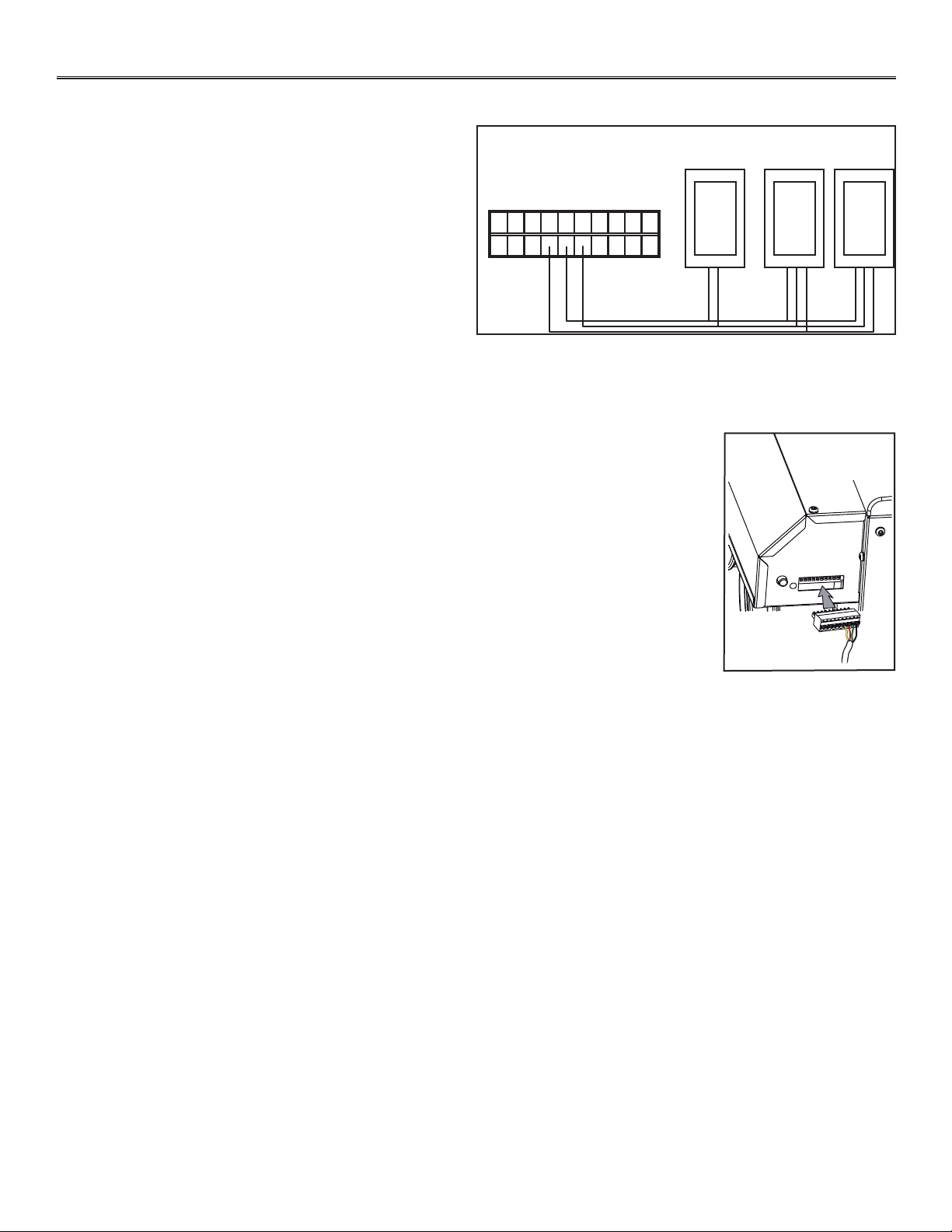
4. CONTROLES (CONTINUACIÓN)
14
VE0273
Una vez conectado el control o controles, introduzca el conector de terminales en la interfaz del
compartimento eléctrico. Enchufe el aparato.
NOTA: Consulte el Main and auxiliary wall control User Guide (en inglés solamente, incluido con la
unidad de ventilación y también disponible en www.broan.com).
4.3 CONEXIÓN ELÉCTRICA CON LOS CONTROLES DE PARED OPCIONALES (CONTINUACIÓN)
NO C NC I OC OL Y R G B
VE0371
59W
VB60W
4.3.5 CONEXIÓN ELÉCTRICA CON CONTROLES DE PARED
AUXILAIRES OPCIONALES
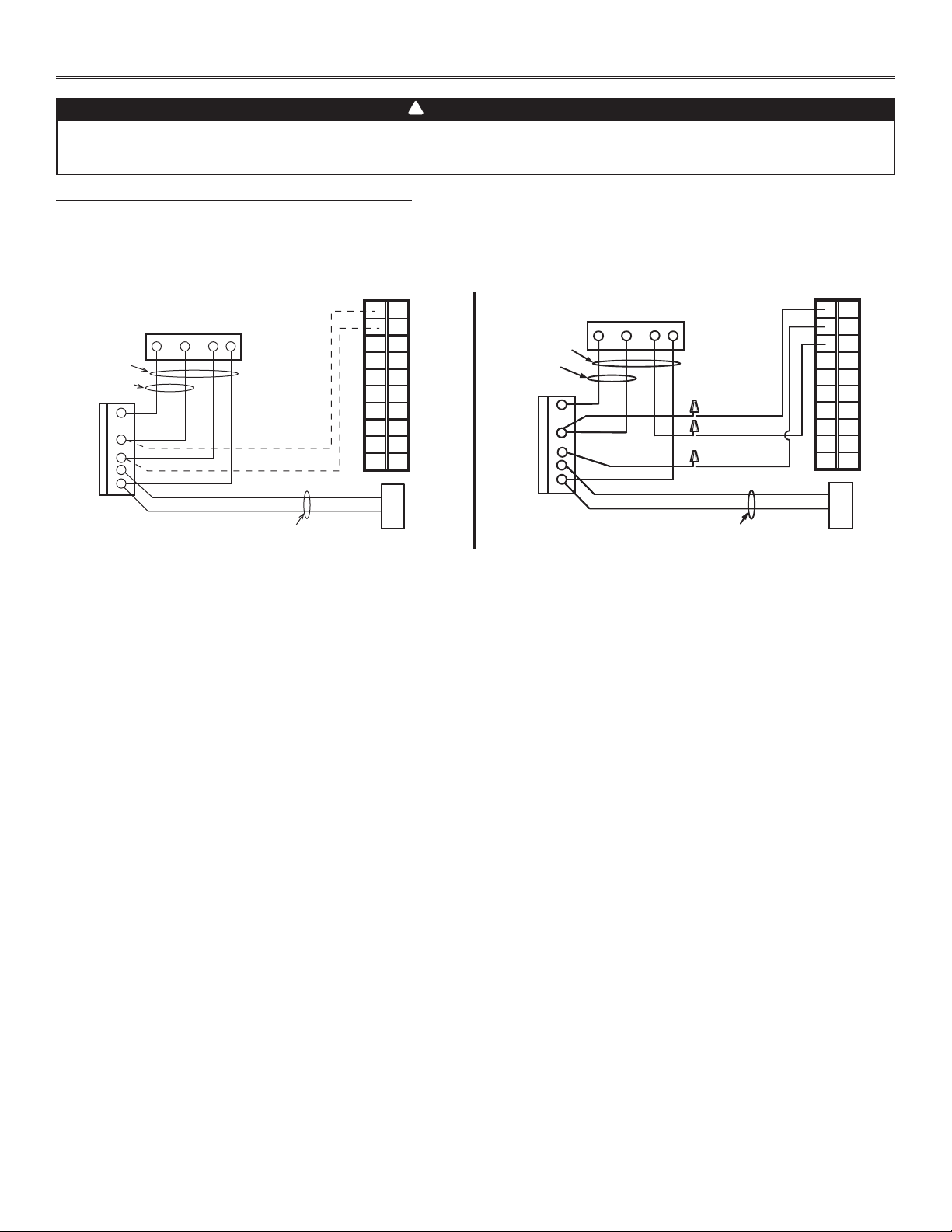
5. CONEXIÓN ELÉCTRICA CON LA CALDERA
15
PARA UNA CALDERA CONECTADA A UN SISTEMA DE REFRIGERACIÓN:
En algunos termostatos más antiguos, si se activan los terminales «R» y «G» en la caldera, se activaría también el terminal «Y» en el
termostato y se pondría en marcha el sistema de refrigeración. Si reconoce este tipo de termostato, utilice el CABLEO DE INTERBLOQUEO
ALTERNATIVO DE LA CALDERA.
ADVERTENCIA
No conecte nunca un circuito de corriente alterna de 120 voltios a los terminales del interbloqueo de la caldera
(cableado estándar). Utilice sólo el circuito de clase 2 de bajo voltaje del control del ventilador impelente de la
caldera.
!
W R G
Y
W
R
G
C
Y
CONECTOR DE TERMINALES DEL APARTO
TERMINALES
DEL TERMOSTATO
CUATRO
CABLES
DOS CABLES
sólo calefacción
BLOQUE DE
TERMINALES DE
24 VOLTIOS DE
LA CALDERA
DOS CABLES
SISTEMA DE
REFRIGERACIÓN
NO C NC I OC OL Y R G B
W R G Y
W
R
Y
R
G
Y
C
CUATRO CABLES
DOS CABLES
tuercas del
cableado
DOS CABLES
NO
NC
C
NO C NC I OC OL Y R G B
VE0108E
SISTEMA DE
REFRIGERACIÓN
BLOQUE DE
TERMINALES DE
24 VOLTIOS DE
LA CALDERA
sólo calefacción
TERMINALES
DEL TERMOSTATO
CONECTOR DE TERMINALES DEL APARTO
CABLEADO DE INTERBLOQUEO ESTÁNDAR DE LA CALDERA CABLEADO DE INTERBLOQUEO ALTERNATIVO DE LA CALDERA
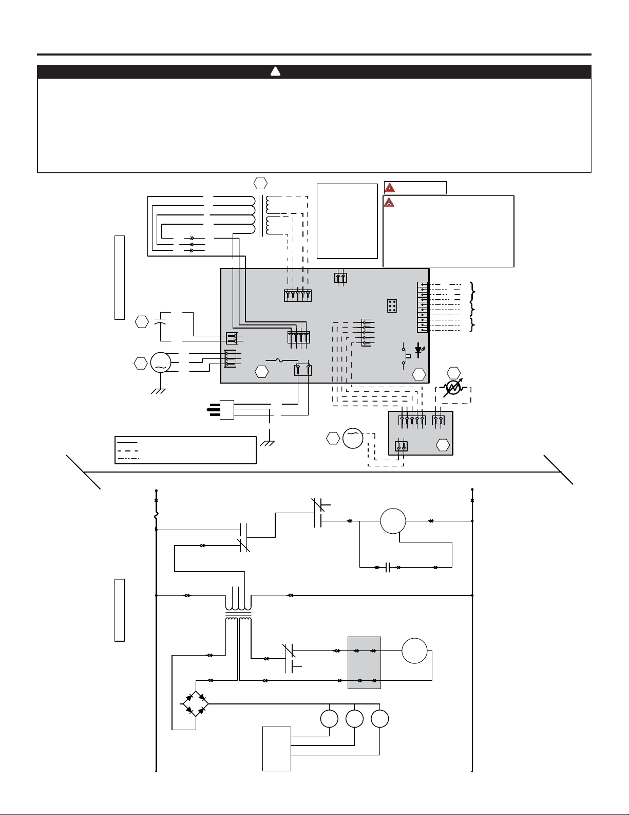
6. DIAGRAMA DE CABLEADOS
16
ADVERTENCIA
!
DIAGRAMA DE CABLEADOS
Característica crítica.
NOTAS
1. Utilice fusibles de línea homologados por CSA
o enumerados por UL.
2. Si hay que sustituir alguno de los cables
originales, utilice cable equivalente.
3. La conexión in situ de la instalación debe respetar
los codigos, ordenanzas y reglamentos aplicables.
4. Controles a distancia (circuito de clase 2)
disponibles, véase el manual de instrucciones.
CODIGO DE
LOS COLORES
J11
12
T1
24 V
Clase 2
9,5 V
Clase 2
N
N
A
A
120 V
106 V
81 V
71 V
Neutral
B
NE
AZ
P
M
R
sc
sc
M
P
AZ
J8
12345
J14
10
9
8
7
6
5
4
3
2
1
J13
ICP
1 2 3 4 5
J12
J9
1234
3A
Tipo 3 AG
21
J10
UNIDAD ELECTRONICA
A1
F1
Interr. de anulación
(opcional; véanse
las notas 3 y 4)
R1
Termistor
J2
J1
1234512
J3
12
A2
UNIDAD ELECTRONICA
DEL REGISTRO
M2
Motor del
registro
NE
NE
NE
B
V
120 Vca
60 Hz
J6
J4
2
1
1
2
3
NE
BL
M
Motor del
ventilador
M1
C1
Condensador
del motor
NE
NE
NE
V
A
NE
V
R
A
OL
OC
I
Véase la
nota 1
120 Vca
Línea
Neutral
J10-2 J10-1
F1 K2
K3
Motor del
ventilador M1
M
M
Motor del
registro M2
J4-1 J4-2
C1
Condensador
del motor
J4-3J6-1 J6-2
J9-4
A2
J2-1 J3-1
J2-2 J3-2
J12-1
J12-2
K4
J8-2
J8-1
J8-5
J8-4
9,5 Vca
24 Vca
T1
sc sc
106 VAC
81 VAC
71 VAC
J9-3
J9-1
~
~
+-
CPU
K4K3K2
DIAGRAMA LÓGICO
VE0291E
R
A AMARILLO
AZ AZUL
B BLANCO
M MARRÓN
P PURPURA
RROJO
V VERDE
sc sin conexión
N NARANJA
NE NEGRO
Cableado de fábrica del voltaje de la línea
Cableado de fábrica de bajo voltaje de clase 2
Cableado in situ de bajo voltaje de clase 2
Cableado in situ del
control a distancia
(véanse las
notas 3 y 4)
Interbloqueo del
ventilador impelente
de la caldera
(opcional; véanse
las notas 3 y 5)
5. El circuito del ventilador de la caldera debe ser
un circuito de clase 2 únicamente.
• Riesgo de choque eléctrico. Antes de realizar cualquier tarea de mantenimiento o reparación, desconecte
siempre la fuente de alimentación.
• El aparato está equipado con una protección contra la sobrecarga (fusible). Un fusible quemado indica que
se ha producido una sobrecarga o cortocircuito. Si el fusible se quema, desenchufe el aparato y verifique la
polaridad y el voltaje en la toma. Sustituya el fusible conforme a las instrucciones de mantenimiento (consulte
el diagrama del cableado para conocer el valor nominal del fusible) y verifique el aparato. Si el nuevo fusible se
quema también, puede tratarse de un cortocircuito. Deje de utilizar el aparato y envíelo a un centro de servicio
autorizado para que lo examinen o reparen.
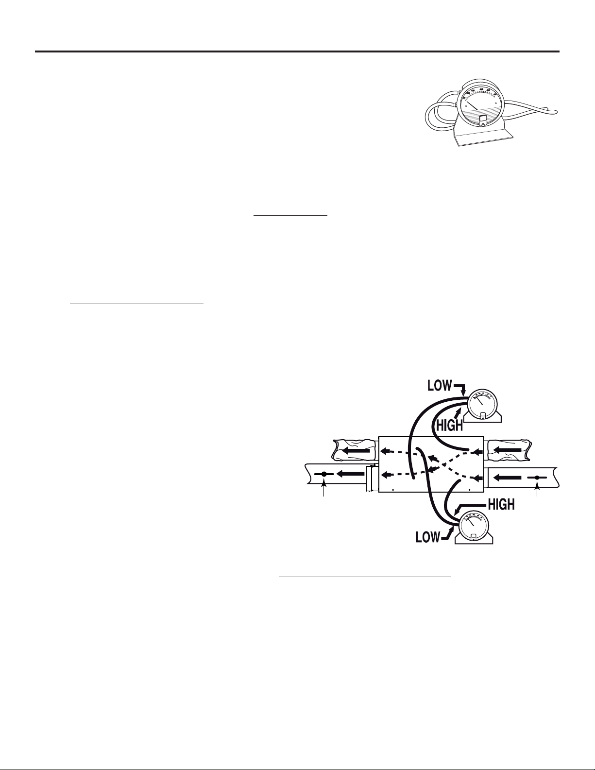
7.1 ELEMENTOS NECESARIOS PARA EQUILIBRAR EL APARATO
• Un caudalímetro de hélice capaz de medir de 0 pulgada a 0,5 pulgadas de agua
(0 Pa a 125 Pa) y 2 tubos de plástico.
• El diagrama de equilibrado situado en la puerta de aparato.
7.2 ETA PAS PRELIMINARES PARA EQUILIBRAR EL APARATO
• Obture todos los tubos del aparato con cinta. Cierre todas las ventanas y puertas.
• Apague todos los dispositivos de extracción, como la campana de cocina, la secadora y los ventiladores del baño.
• Compruebe que los regitros de equilibrio están totalmente abiertos.
NOTA: Los registros de equilibrio NO ESTÁN INCLUIDOS
; deberán conseguirse aparte. Instale los registros de equilibrio en
el tubo de aire fresco al edificio y en el tubo de aire de salida desde el edificio (A y B en la ilustración de abajo), en el lugar más
cómodo.
• Compruebe que todos los filtros estén limpios (si no es la primera vez que equilibra el aparato).
7.3 PROCEDIMIENTO DE EQUILIBRADO
1. Ponga el aparato en velocidad alta.
Compruebe que el ventilador impelente de la caldera/armario de tratamiento del aire esté en posición ON (encendido)
si la instalación está de alguna forma conectada a los tubos de retorno de aire frío. De no ser así, deje el ventilador
impelente de la caldera/armario de tratimiento del aire en posición OFF (apagado). Si la temperatura exterior es inferior a
32°F, verifique que el aparato no esté funcionando en modo deshielo mientras procede al equilibrado. (Si espera 10 minutos tras
enchufar el aparato, tendrá la certeza de que el aparato no está en el ciclo de deshielo.)
2. Coloque el caudalímetro de hélice sobre una superficie a nivel y póngalo en cero.
3. Conecte los tubos del caudalímetro a las tomas de presión
de la corriente de aire SALIDA (véase el diagrama al lado).
Compruebe que conecta los tubos a los empalmes
apropriados high (alto) o low (baja). Si el caudalímetro
desciende por debajo de cero, invierta las conexiones de
los tubos.
NOTA: Se sugiere empezar por medir la corriente del aire
de salida porque habitualmente el aire la salida tiene
más restricciones que el aire puro, sobre toto en los
casos de instalaciones completamente entubadas
o de ventilación en el punto de origen. Coloque el
caudalímetro de hélice en posición vertical y a nivel.
Registre la CORRIENTE DE AIRE equivalente al
resultado del caudalímetro con arreglo al diagrama
de equilibrado.
4. Ponga los tubos del caudalímetro en las tomas de presión de la corriente de aire PURO (véase el diagrama). Regule el registro
de equilibrio del aire puro (A) hasta que la corriente de aire puro sea aproxidamente la misma que la de aire de SALIDA. Si la
corriente de aire puro es inferior a la de aire de salida, regule el registro de equilibrio del aire salida (B) al mismo nivel que el del
aire puro.
5. Sujete ambos registros con un tornillo de sujeción.
6. Escriba los datos necesarios sobre la corriente de aire en una etiqueta y péguela cerrca del aparato par futuras consultas (fecha,
velocidad máxima de las corrientes de aire, su nombre, teléfono y dirección profesional).
NOTA: Se considera que el aparato está equilibrado au cuando una diferancia de ±10 pi³/m (o ± 5 l/s) entre las dos corrientes
de aire.
VP0009
7. E QUILIBRADO DEL APARATO
17
VP0024
AB
CORRIENTE DE
AIRE DE SALIDA
CORRIENTE DE
AIRE PURO
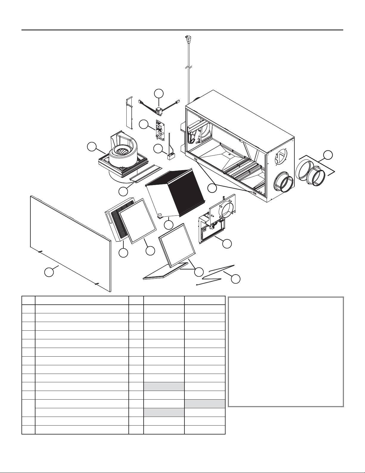
18
8. PIEZAS DE RECAMBIO
1
2
3
4
5
6
7
8
9
11
12
13
14
VL0062
10
N. DESCRIPCIÓN CTD HRVH100S ERVH100S
1TRANSFORMADOR 1 SV61545 SV61545
2TARJETA ELECTRÓNICA 1 SV61415 SV61184
3CAPACITOR 6 F 1 SV61550 SV61550
4CONJUNTO DEL VENTILADOR 1 SV61552 SV61552
5SOPORTE DE LA UNIDAD CENTRAL 1 SV61553 SV61553
6CONJUNTO DE LA PUERTA 1 SV63625 SV63625
7JUEGO DE FILTROS HEPA
1
1 SV21293 SV21293
8JUEGO DE PREFILTROS PARA FILTRO HEPA
2
1 SV61561 SV61561
9FILTRO DEL NÚCLEO 2 SV61563 SV61562
10 ALAMBRE DE RETENCIÓN DEL FILTRO INFERIOR 1 SV61564
11 CONJUNTO DEL SISTEMA DEL REGISTRO 1 SV61565 SV61565
12
NÚCLEO DE RECUPERACIÓN DE CALOR 1 SV61567
NÚCLEO DE RECUPERACIÓN DE ENERGÍA 1 SV61410
13 SOPORTE CON TUERCA DE RETENCIÓN 2 SV61411 SV61411
14 BOCA DE DOBLE ANILLO 2 SV61569 SV61569
REPUESTOS Y REPARACIONES
Para que el aparato de ventilación esté
en buenas condiciones sólo debe utilizar
repuestos Broan-NuTone LLC genuinos. Los
repuestos Broan-NuTone LLC genuinos han
sido diseñados especialmente para cada
aparato, han sido fabricados de conformidad
con todas las normas de certificación aplicables
y ofrecen un alto nivel de seguridad. El uso de
repuestos diferentes puede provocar daños
graves y reducir drásticamente el nivel de
rendimiento del aparato, lo cual podría causar
una avería prematura. Broan-NuTone LLC
aconseja ponerse en contacto con un taller de
servicio autorizado para cualquier cambio de
pieza y reparación.
¹ EL JUEGO DE FILTROS HEPA INCLUYE 2 PREFILTROS.
² EL JUEGO DE PREFILTROS INCLUYE 2 PREFILTROS.
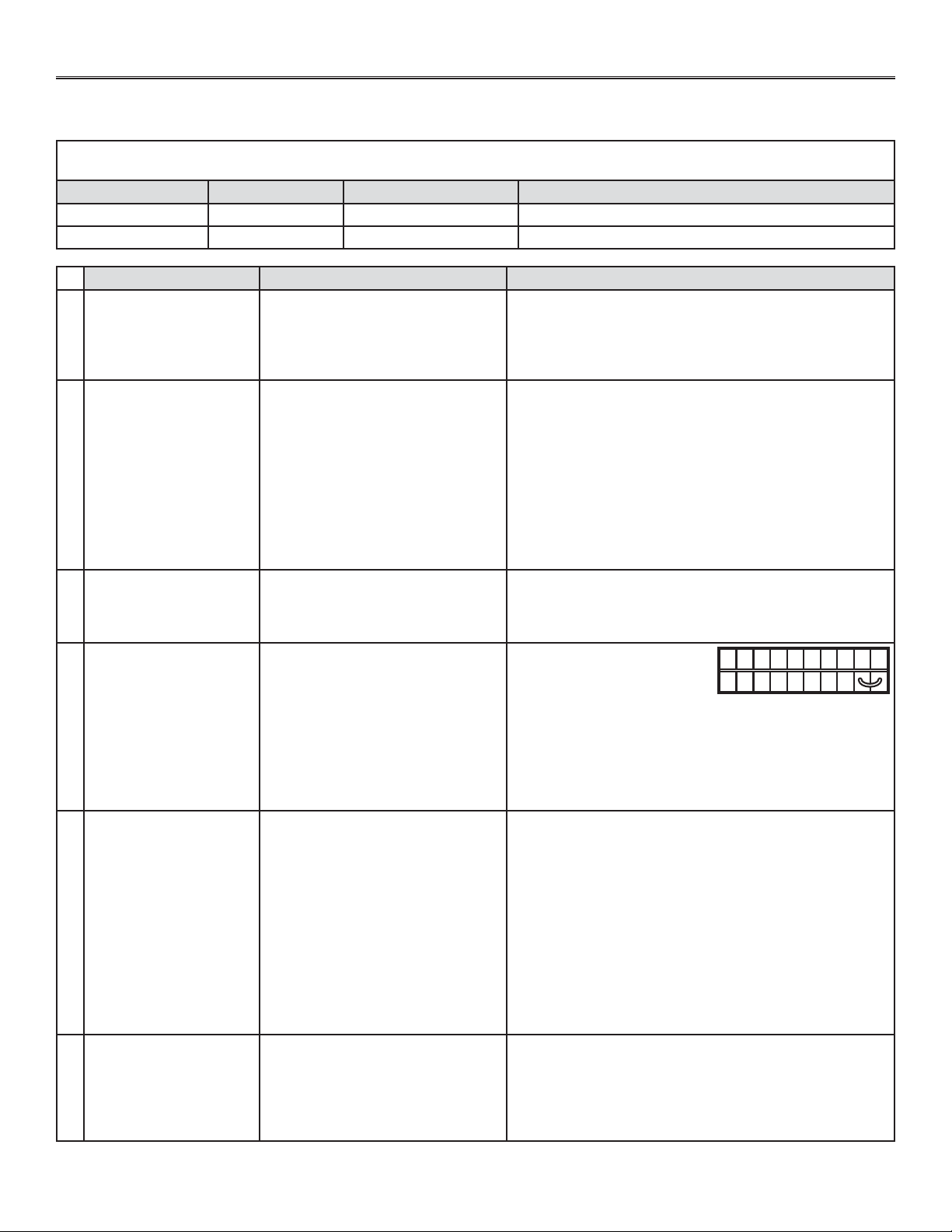
19
9. SOLUCIÓN DE PROBLEMAS
Si el aparato no funciona bien, reinícielo desenchufándolo durante un minuto y vuélvalo a enchufar. Si sigue sin funcionar bien,
consulte la tabla de abajo.
Si el diodo luminiscente (LED) del control integrado del aparato parpadea, significa que los sensores del aparato han detectado un
problema. Consulte la tabla de abajo para saber dónde se produce el problema en el aparato.
COLOR DEL DIODO TIPO DE ERROR MEDIDA ESTADO DEL APARATO
Parpadea en VERDE Error del termistor Sustituya el termistor Funciona pero descongela con frecuencia
Parpadea en ÁMBAR Error del registro Vaya al punto 6 No funciona
PROBLEMA CAUSAS POSIBLES SOLUCIONES POSIBLES
1
El código de error E1
aparece en la pantalla
del control mural principal
VT8W o VT7W.
• Los hilos pueden estar en posición
invertida.
• Los hilos pueden estar rotos.
• Los hilos pueden estar mal
conectados.
• Compruebe que los hilos de colores se han conectado en
los lugares correspondientes.
• Examine cada hilo y sustituya los que estén dañados.
• Compruebe que los hilos se han conectado correctamente.
2
No hay temperatura
exterior en la pantalla
del control mural VT8W
__.
• El termistor del aparato está
defectuoso (el diodo del control
integrado del aparato debe
parpadear en VERDE).
NOTA: en la primera puesta en marcha o tras una interrupción
de la alimentación transcurrirán algunos minutos hasta
que aparezca en la pantalla la temperatura exterior.
La demora depende del modo de funcionamiento
establecido para el control mural. La demora es más
breve cuando se ha seleccionado el modo VENT en la
opción MIN o MAX.
• Sustituya el termistor del aparato.
3
La pantalla del control
mural VT8W o
VT7W alterna entre
normal y E3.
• El control mural VT8W o VT7W
debe estar defectuoso.
• Sustituya el control mural VT8W o VT7W.
4
El aparato no funciona. • La placa de circuitos puede estar
defectuosa.
• El fusible puede estar defectuoso.
5
El accionador del registro
no funciona.
• El accionador o el mecanismo
integrado del registro pueden estar
defectuosos.
• La placa de circuitos o el
transformador pueden estar
defectuosos.
• Desenchufe el aparato. Desconecte el control principal y los
opcionales (de haberlos). Espere 10 segundos y vuelva a
enchufar el aparato. Verifique si el registro se abre. Si no
se abre, use un multímetro y verifique si hay una señal de
24 V CA en J12-1 y J12-2 (en el compartimento eléctrico).
Si hay señal de 24 V CA, sustituya el conjunto del registro.
NOTA: es normal que haya una pequeña demora
(7-8 segundos) hasta que se detecte la señal de
24 V CA. La señal permanecerá 17-18 segundos y
luego desaparecerá.
• Si no hay señal de 24 V CA, verifique si la hay entre J8-1 y
J8-2. Si hay señal, sustituya la placa de circuitos y, si no la
hay, cambie el transformador.
6
El control mural no
funciona.
• Los hilos pueden estar en posición
invertida.
• Los hilos pueden estar rotos.
• El hilo de la pared O el control mural
pueden estar defectuosos.
• Compruebe que los hilos de colores se han conectado en
los lugares apropiados.
• Examine cada hilo y sustituya los que estén dañados.
• Retire el control mural y pruébelo junto al aparato con un
hilo más corto. Si el control mural funciona, cambie el hilo.
Si no funciona, cambie el control mural.
• Desenchufe el aparato.
Desconecte el control
principal y los opcionales
(de haberlos). Conecte
provisionalmente los terminales G y B. Vuelva a enchufar
el aparato y espere unos 10 segundos. Si los motores
funcionan a alta velocidad y el registro de abre, la placa de
circuitos no está defectuosa.
• Verifique si el fusible F1 está quemado. De estarlo,
sustitúyalo conforme a la placa de datos del producto.
NO C NC I OC OL Y R G B
VE0097
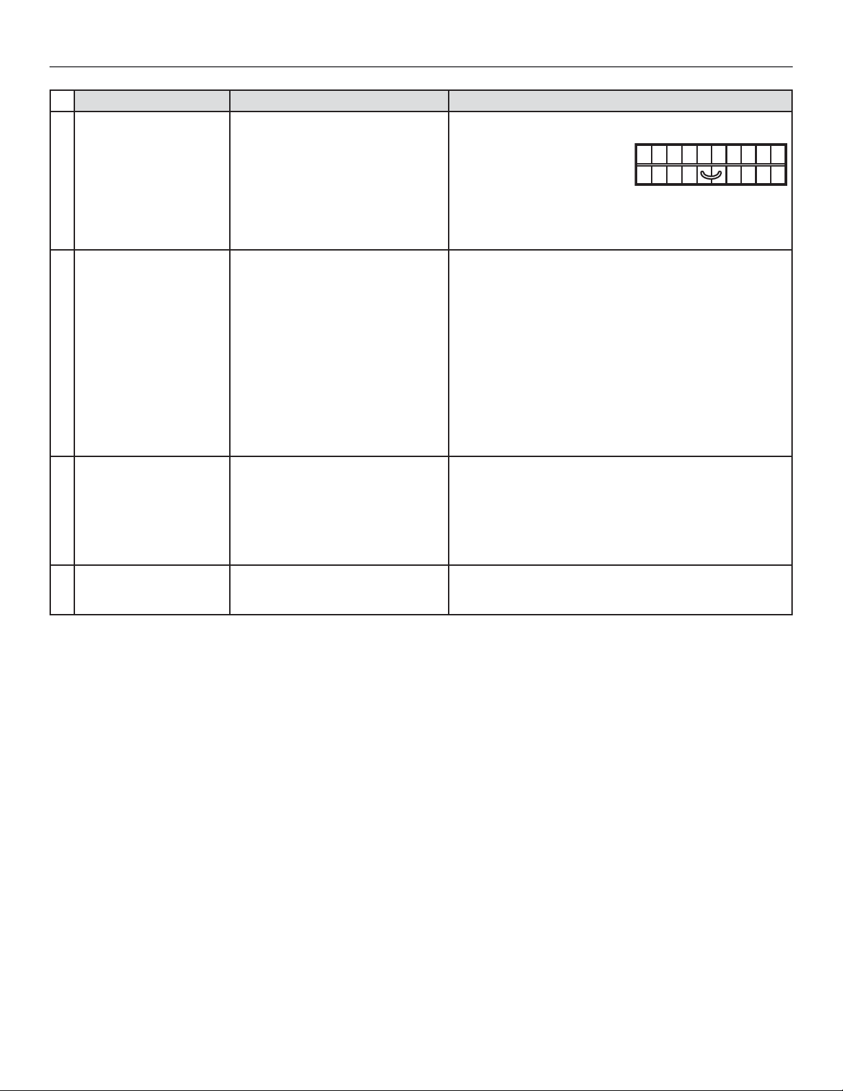
20
9. SOLUCIÓN DE PROBLEMAS (CONTINUACIÓN)
• Compruebe que los hilos de colores se han conectado en
los lugares correspondientes.
• Conecte provisionalmente
los terminales OL y OC. Si el
aparato pasa a alta velocidad,
retire el botón pulsador
VB60W y pruébelo junto al aparato con un cable más corto.
Si funciona así, cambie el hilo. Si no funciona, cambie el
botón pulsador VB60W.
NO C NC I OC OL Y R G B
VE0098
PROBLEMA CAUSAS POSIBLES SOLUCIONES POSIBLES
7
El temporizador de botón
pulsador de VB60W no
funciona O su indicator
luminoso no permanece
encendido.
• Los hilos pueden estar en posición
invertida.
• El botón pulsador VB60W puede
estar defectuoso.
8
El motor no funciona. • El fusible puede estar defectuoso.
• El motor puede estar defectuoso.
• El motor o el condensador pueden
estar defectuosos.
• Verifique si el fusible F1 está quemado. De estarlo,
sustitúyalo conforme a la placa de datos del producto.
NOTA: consulte la sección 6. Diagrama de cableados.
• Si el voltaje es de 120 V CA en J4, cambie el motor
defectuoso.
• Use un multímetro para verificar los ohmios en el conector
del motor. En los hilos AZUL y NEGRO del motor el valor
correcto es de ± 43 ohmios. En los hilos AZUL y MARRÓN
del motor el valor correcto es de ± 48 ohmios. En los hilos
MARRÓN y NEGRO del motor el valor correcto es de
± 91 ohmios. Si los valores en ohmios son los mismos, el
motor no está defectuoso. Sustituya el condensador del
motor.
9
El ciclo de descongelación
no funciona (el tubo de aire
fresco está congelado) O
el aire fresco distribuido
está muy frío.
• Depósitos de hielo podrían
obstaculizar el funcionamiento del
registro.
• La varilla del registro o el registro de
la boca pueden estar rotos.
• El activador del registro o la placa de
circuitos pueden estar defectuosos.
• Retire el hielo.
• Examine estas piezas y sustitúyalas de ser necesario.
• Vea el punto 5.
10
El botón pulsador de
control de descongelación
integrado no funciona.
• La secuencia de puesta en
marcha de 30 segundos no se ha
completado.
• Véase la sección 4.1 Secuencia de puesta en marcha.
Si el problema persiste, llame nuestro departemento de asistencia técnica: 1-800-543-3055.