Loading ...
Loading ...
Loading ...
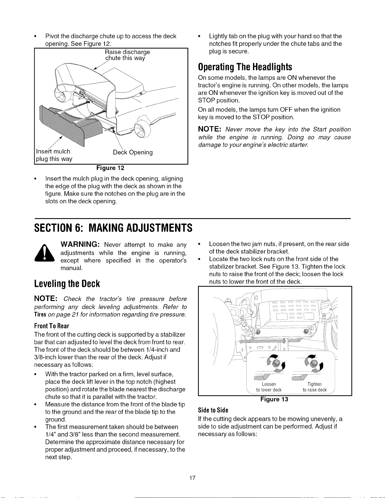
Pivot the discharge chute up to access the deck
opening. See Figure 12.
Raise discharge
chute this way
Inse_t mulch Opening
plug this way
Figure 12
Insert the mulch plug in the deck opening, aligning
the edge of the plug with the deck as shown in the
figure. Make sure the notches on the plug are in the
slots on the deck opening.
• Lightly tab on the plug with your hand so that the
notches fit properly under the chute tabs and the
plug is secure.
OperatingTheHeadlights
On some models, the lamps are ON whenever the
tractor's engine is running. On other models, the lamps
are ON whenever the ignition key is moved out of the
STOP position.
On all models, the lamps turn OFF when the ignition
key is moved to the STOP position.
NOTE: Never move the key into the Start position
while the engine is running. Doing so may cause
damage to your engine's electric starter.
SECTION6: MAKINGADJUSTMENTS
_, WARNING: Never attempt to make any
adjustments while the engine is running,
except where specified in the operator's
manual.
LevelingtheDeck
NOTE: Check the tractor's tire pressure before
performing any deck leveling adjustments. Refer to
Tires on page 21 for information regarding tire pressure.
FrontTo Rear
The front of the cutting deck is supported by a stabilizer
bar that can adjusted to level the deck from front to rear.
The front of the deck should be between 1/4-inch and
3/8-inch lower than the rear of the deck. Adjust if
necessary as follows:
• With the tractor parked on a firm, level surface,
place the deck lift lever in the top notch (highest
position) and rotate the blade nearest the discharge
chute so that it is parallel with the tractor.
• Measure the distance from the front of the blade tip
to the ground and the rear of the blade tip to the
ground.
• The first measurement taken should be between
1/4" and 3/8" less than the second measurement.
Determine the approximate distance necessary for
proper adjustment and proceed, if necessary, to the
next step.
Loosen the two jam nuts, if present, on the rear side
of the deck stabilizer bracket.
Locate the two lock nuts on the front side of the
stabilizer bracket. See Figure 13. Tighten the lock
nuts to raise the front of the deck; loosen the lock
nuts to lower the front of the deck.
jT_ ..............................
/
Loosen Tighten
\ .............................................../
Figure 13
Sideto Side
If the cutting deck appears to be mowing unevenly, a
side to side adjustment can be performed. Adjust if
necessary as follows:
17
Loading ...
Loading ...
Loading ...