Loading ...
Loading ...
Loading ...
SERVICE AND ADJUSTMENTS
SIDE-TO-SIDE ADJUSTMENT (See Figs. 19 and 20)
• Raise mower to itshighest position.
• At the midpoint of both sides of mower, measu re height
from bottom edge of mower to ground. Distance"A" on
both sides of mower should be the same or within 1/4"
of each other.
• If adjustment is necessary, make adjustment on one
side of mower only.
• To raise one side of mower, tighten lift link adjustment
nut on that side.
• To lower one side of mower, loosen lift link adjustment
nut on that side.
NOTE: Three fultturnsof adjustment nutwill change mower
height about 1/8".
Recheck measurements after adjusting.
BOTTOM EDGE OF BOTTOM EDGE OF
MOWER TO GROUND MOWER TO GROUND
FIG. 19
LIFT
LINK ADJUSTME_N_T NUT"
FIG. 20
FRONT-TO-BACK ADJUSTMENT (See Figs. 21 and 22)
IMPORTANT: DECK MUST BE LEVEL SIDE-TO-SIDE. IF
THE FOLLOWING FRONT-TO-BACK ADJUSTMENT IS
NECESSARY, BE SURE TO ADJUST BOTH FRONT LINKS
EQUALLY SO MOWER WILL STAY LEVEL SIDE-TO-
SIDE.
To obtain the best cutting results, the mower housing should
be adjusted so that the front is approximately 1/8" to 1/2"
lower than the rear when the mower is in its highest position.
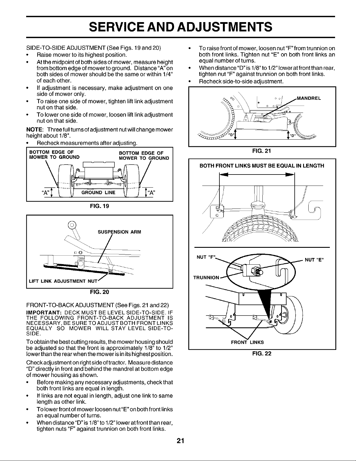
Check adjustment on right side oftractor. Measure distance
"D" directly in front and behind the mandrel at bottom edge
of mower housing as shown.
• Before making any necessary adjustments, check that
both front links are equal in length.
• If links are not equal in length, adjust one link to same
length as other link.
• Tolowerfrontofmowerloosennut"E'onbothfrontlinks
an equal number of turns.
• When distance "D"is 1/8" to 1/2" lower atfront than rear,
tighten nuts "F" against trunnion on both front links.
21
• To raise front of mower, loosen nut "F" from trunnion on
both front links. Tighten nut "E" on both front links an
equal number of turns.
• When distance "D"is 1/8" to 1/2" lower atfront than rear,
tighten nut "F" against trunnion on both front links.
• Recheck side-to-side adjustment.
FIG. 21
BOTH FRONT LINKS MUST BEEQUAL IN LENGTH
NUT "E"
FRONT LINKS
FIG. 22
Loading ...
Loading ...
Loading ...