
COMPANION PRODUCTS
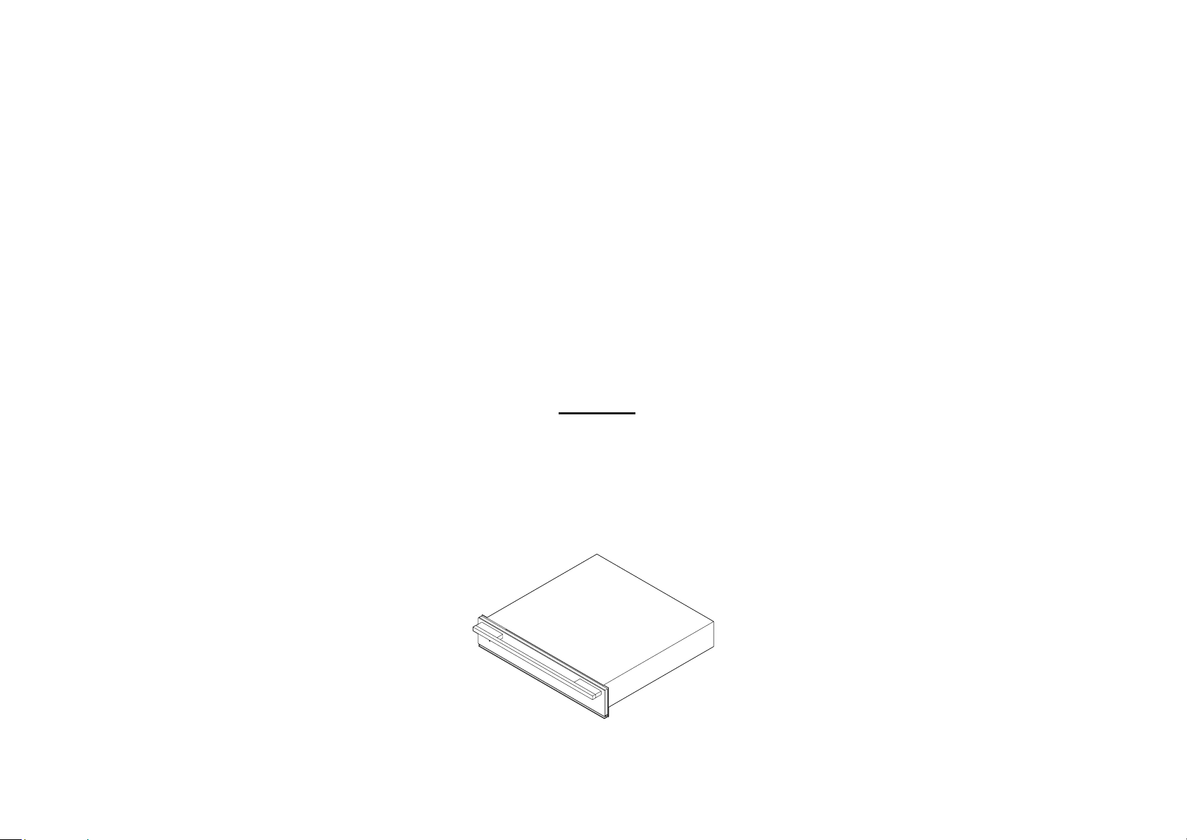
Warming Drawer WB24
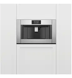
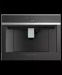
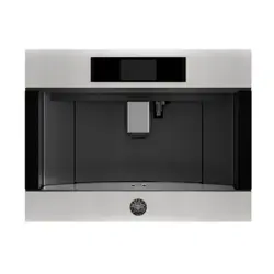
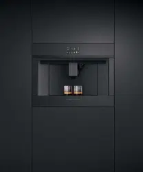
Coee Maker EB24
Steam Oven OS24N
Speed Oven OM24N
models
INSTALLATION GUIDE
US CA
591496F 08.20

CONTENTS
IMPORTANT!
SAVE THESE INSTRUCTIONS
Warming drawer 1
1 Safety and warnings 2
2 Parts supplied 3
3 Prior to installation 3
4 Product dimensions 4
5A Cabinetry dimensions – underbench
(ie installed with F&P single oven) 5
5B Cabinetry dimensions – wall mounted
(ie installed with a F&P compact oven) 6
5C Cabinetry dimensions – wall mounted
(ie installed with a F&P coffee maker) 7
5D Cabinetry dimensions – wall mounted
(standalone) 8
6 Discard packaging responsibly 9
7 Mark and pre-drill the holes for securing
the warming drawer 9
8 Connect the warming drawer to the mains supply 9
9 Secure the warming drawer to the cabinetry 10
10 Secure the anti-tip bracket
(optional depending on cabinetry configuration) 10
11 Final checklist 11
Coffee maker 12
1 Safety and warnings 13
2 Parts supplied 14
3 Prior to installation 14
4 After installation 14
5 Product dimensions 15
6A Cabinetry dimensions
(18 1/8" (460mm) high cavity) 16
6B Cabinetry dimensions
(18 7/8" (480mm) cavity trim kit) 17
7 Installation instructions 18
8 Connect the warming drawer to the mains supply 19
9 Final checklist 20
Steam oven 21
1 Safety and warnings 22
2 Prior to installation 23
3 After installation 23
4 Product dimensions 24
5A Cabinetry dimensions
(18 1/8" (460mm) high cavity) 25
5B Cabinetry dimensions
(18 7/8" (480mm) cavity trim kit) 26
6 Electrical hook-up 27
7 Secure the oven to the cabinetry 27
8 Final checklist 28
Speed oven 29
1 Safety and warnings 30
2 Prior to installation 31
3 After installation 31
4 Product dimensions 32
5A Cabinetry dimensions
(18 1/8" (460mm) high cavity) 33
5B Cabinetry dimensions
(18 7/8" (480mm) cavity trim kit) 34
6 Electrical hook-up 35
7 Secure the oven to the cabinetry 35
8 Final checklist 36
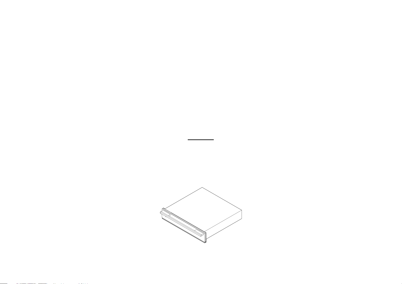
WARMING DRAWER
WB24 models

2 | WARMING DRAWER INSTALLATION GUIDE
IMPORTANT!
SAVE THESE INSTRUCTIONS
1 SAFETY AND WARNINGS
●
The electrical outlet should be easily accessible after installation.
●
When a companion product is installed in combination with the warming drawer to
the same circuit, operating both products may cause an overload. If in doubt consult a
qualified electrician.
●
When installed in combination with a companion product the companion product may be
placed directly onto the warming drawer. It is not necessary to place a shelf between the
products. A built-in shelf at the base of the cabinetry able to support the weight of both
products is required.
●
If installing the warming drawer directly underneath an oven, ensure you do not damage
the oven’s lower trim. The lower trim ensures correct air circulation to the oven and allows
the door to open and close without obstruction. Fisher & Paykel does not accept any
responsibility for any damage resulting from incorrect installation.
●
The maximum weight the warming drawer is able to support is 132lb (60kg).
●
The warming drawer is not designed for use in mobile installations such as recreational
vehicles, boats or aircraft.
●
When installing companion products the weight of the companion product should be
distributed across the edges of the warming drawer. Products above which rest on ‘feet’
may only be installed if the feet of the product lie within 2 3/4" (70mm) of the sides of
the warming drawer, as this area is reinforced. Failure to do this may result in damage to
the warming drawer and companion product.
●
Before installing the warming drawer you must inspect it for any signs of damage. Under no
circumstances should you install or use the warming drawer if it has been damaged.
●
If the power supply cord is damaged, it must be replaced by the manufacturer, its service
agent or a similarly qualified tradesperson in order to avoid a hazard.
●
Connect the warming drawer to a properly rated, protected and sized power supply circuit
to avoid electrical overload.
●
Do not use an extension cord or a portable electrical outlet device (eg multi-socket outlet
box) to connect the Warming Drawer to the power supply. Make sure the power supply
cord is located so that it will not be stepped on, tripped over or otherwise subject to
damage or stress.
●
Ensure the connection to power supply is accessible after installation.
IMPORTANT SAFETY INSTRUCTIONS!
To reduce the risk of fire, electrical shock, injury to person, or damage when using the
warming drawer, please read these instructions carefully before installing this product.
●
Please make this information available to the person installing the product – doing so
may reduce your installation costs.
●
Installation work, maintenance and repairs may only be carried out by suitably qualified
and competent persons in accordance with national and local safety regulations.
●
Always disconnect the power supply prior to carrying out any installation, maintenance
or repair work.
●
Before installation make sure that the voltage and frequency listed on the data plate
corresponds with the household electrical supply.
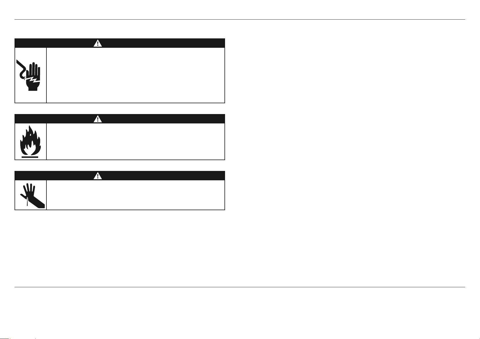
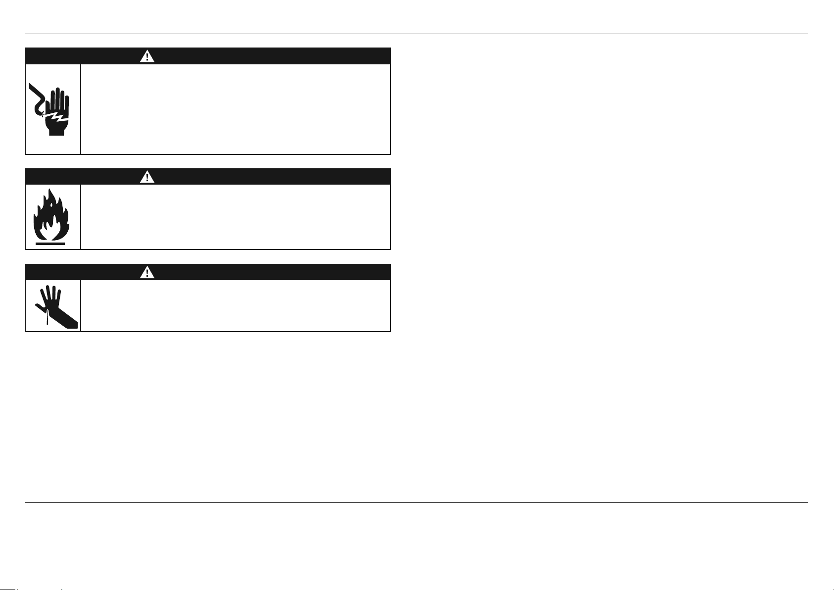
WARNING!
Cut Hazard
Take care – some edges are sharp.
Failure to use caution could result in injury or cuts.
WARNING!
Fire Hazard
Do not use adapters, reducers, or branching devices to connect this
appliance to the mains power supply.
Failure to follow this advice may result in overheating, burning, or fire.
WARNING!
Electrical Shock Hazard
Before carrying out any work on the electrical section of the appliance,
it must be disconnected from the mains electricity supply.
Connection to a good earth wiring system is absolutely essential and
mandatory.
Alterations to the domestic wiring system must only be made by a
qualified electrician.
Failure to follow this advice may result in electrical shock or death.
WARMING DRAWER INSTALLATION GUIDE | 3
3 PRIOR TO INSTALLATION
●
The cavity is square and level, and of the required dimensions.
●
The installation will comply with all clearance requirements and applicable standards and regulations.
●
The power switch will be easily accessible to the customer when the warming drawer is installed.
●
The warming drawer (and any product on top of it) will rest on a surface that can support its weight.
●
The height from the floor suits the customer.
●
You consult local building authorities and by-laws if in doubt regarding installation.
If installing with a companion product
IMPORTANT!
●
If installing with a companion product please refer to the installation instructions of that product to ensure the installation requirements of BOTH products are met.
●
When installing products on top of the warming drawer, the weight of the product should be distributed across the edges of the warming drawer.
●
Products above which rest on ‘feet’ may only be installed if the feet of the product lie within 2 3/4" (70mm) of the sides of the warming drawer, as this area is reinforced.
Failure to do this may result in damage to the warming drawer and companion product.
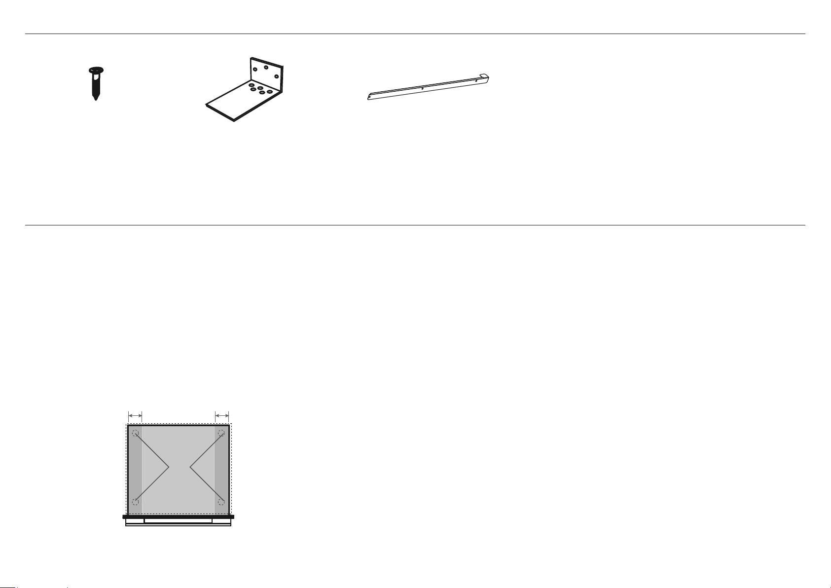
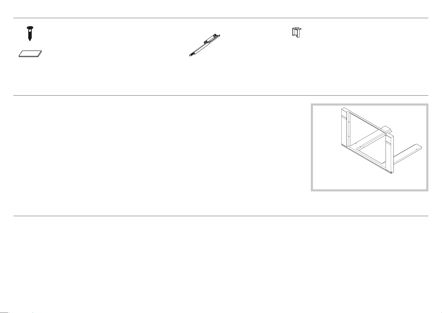
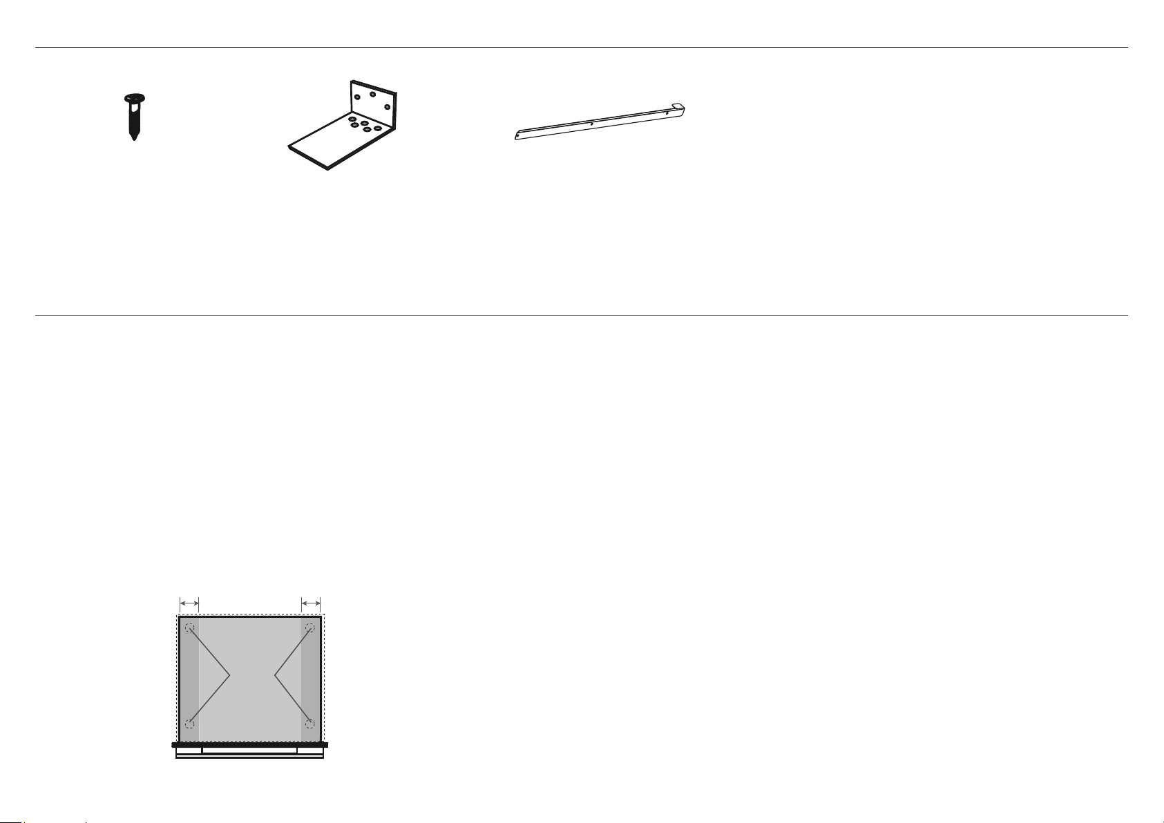
Screws (4) Anti-tip bracket (1) Oven support brackets (2)
Warming Drawer can withstand
a maximum weight of 132lb (60kg)
2 3/4"
(70mm)
2 3/4"
(70mm)
Feet
2 PARTS SUPPLIED
4 | WARMING DRAWER INSTALLATION GUIDE
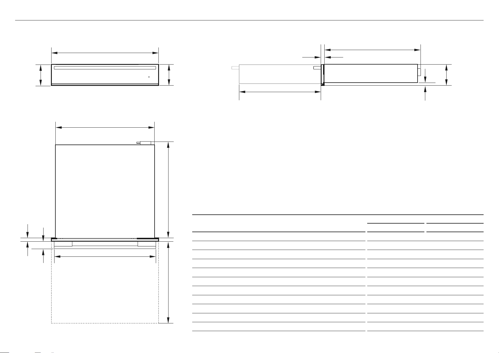
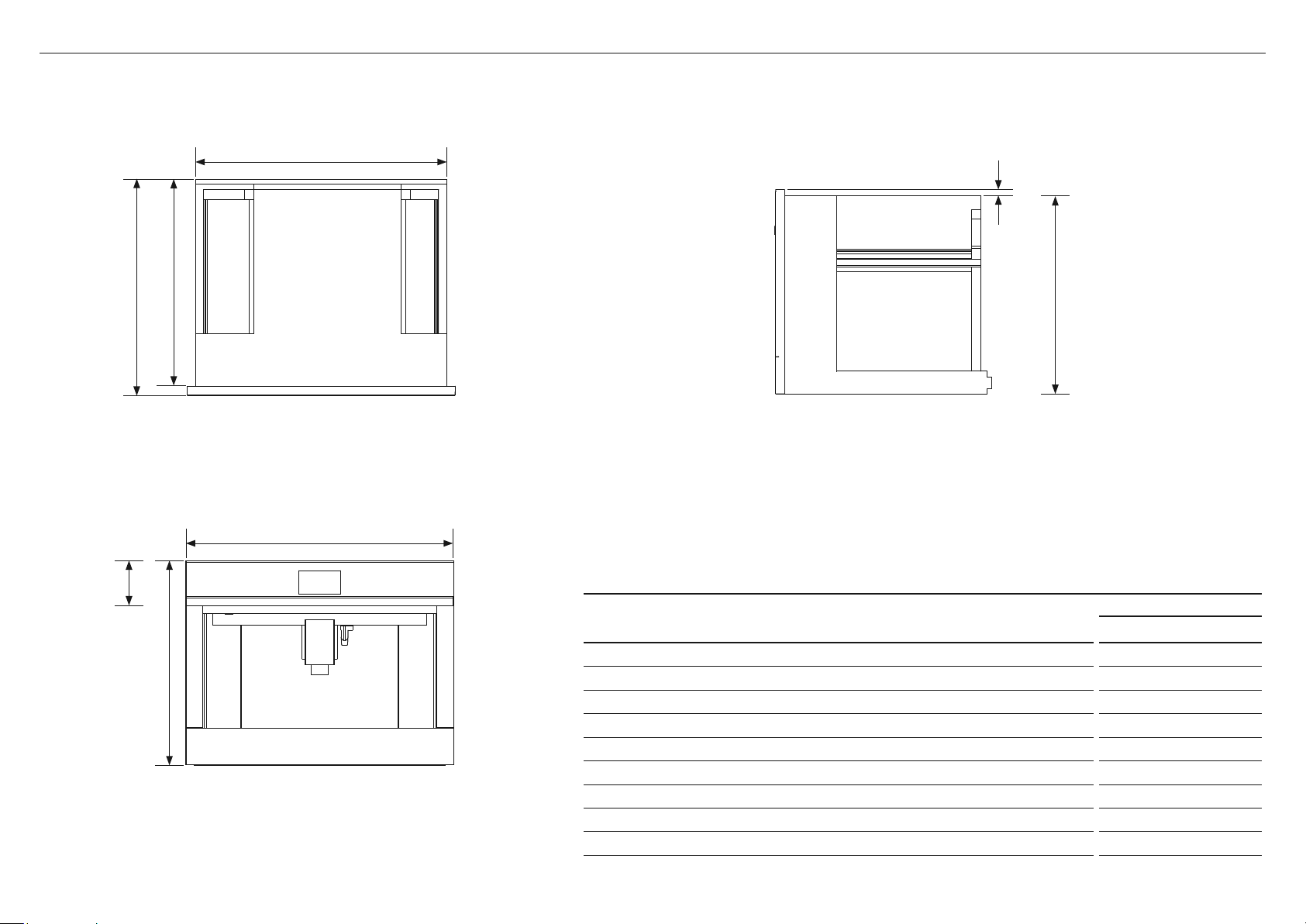
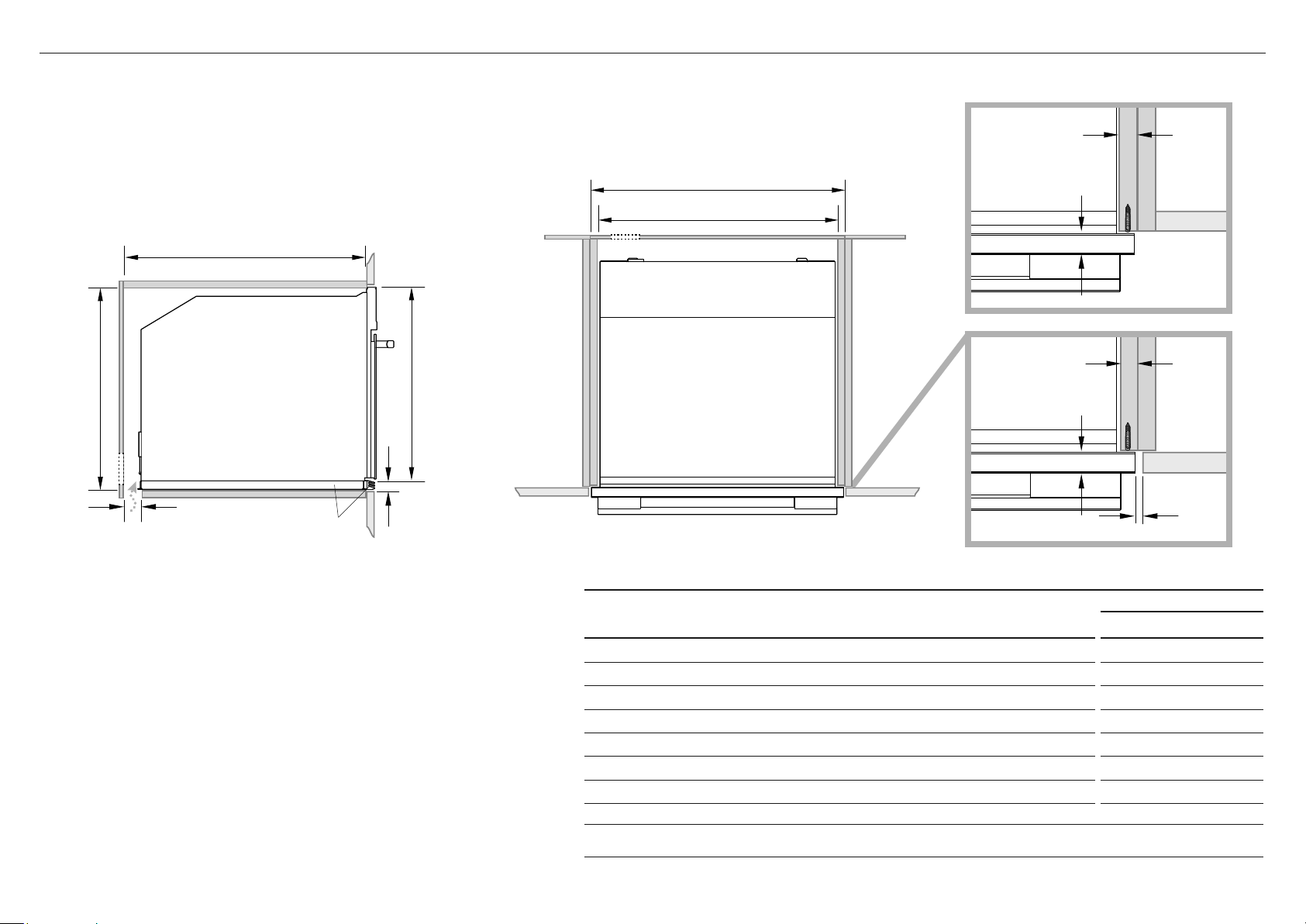
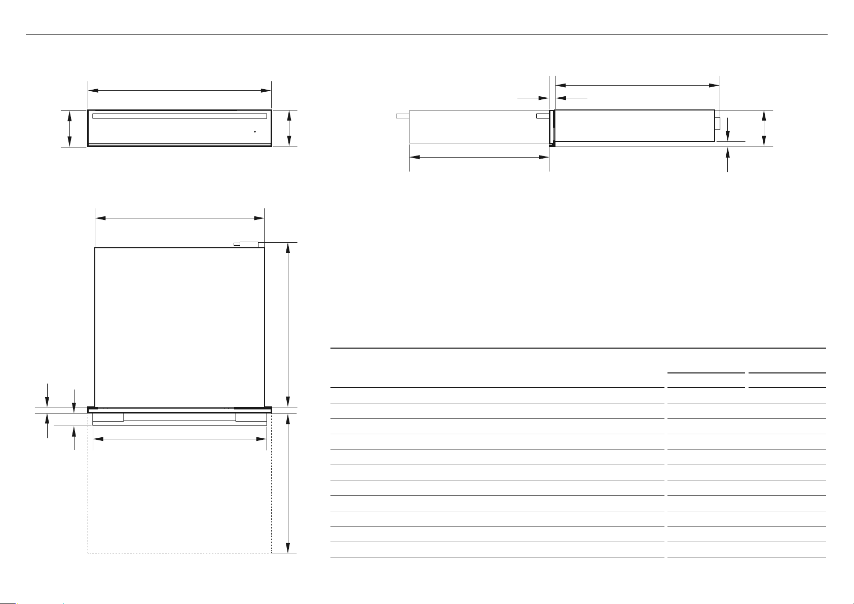
4 PRODUCT DIMENSIONS
PLAN
FRONT
Terminal Block
SIDE
PRODUCT DIMENSIONS
WB24SDEB WB24SDEX
inches (mm) inches (mm)
A
Overall height of product 4 5/" (118) 4 5/8" (118)
B
Overall width of product 23 1/2" (596) 23 1/2" (596)
C
Depth of drawer front panel (excluding handle)* 13/16" (20) 7/8" (22)
D
Depth of chassis (including terminal block) 21 1/8" (536) 21 1/8" (536)
E
Width of chassis at rear 21 3/4" (551) 21 3/4" (551)
F
Height from bottom drawer panel to bottom of chassis at rear 5/8" (16) 5/8" (16)
G
Height from bottom of drawer panel to top of chassis 4 5/8" (118) 4 5/8" (118)
H
Depth of drawer (open) (measured from front of drawer) 17 7/8" (455) 17 7/8" (455)
I
Height of drawer front panel 4 5/8" (116) 4 5/8" (116)
J
Depth of handle measured from front of drawer 1 5/8" (41) 1 5/8" (41)
K
Width of handle 22 1/4" (565) 22 1/4" (565)
A
B
I
C
D
F
G
E
D
H
K
JC
WARMING DRAWER INSTALLATION GUIDE | 5
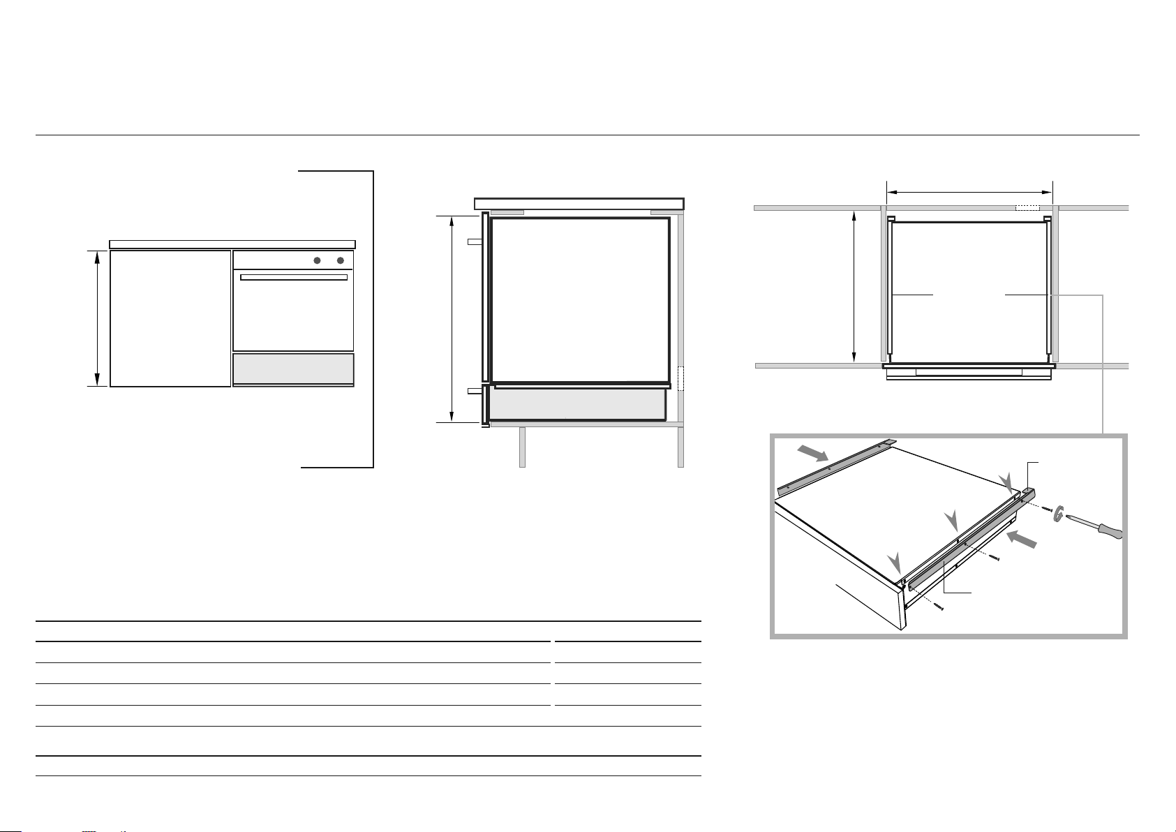
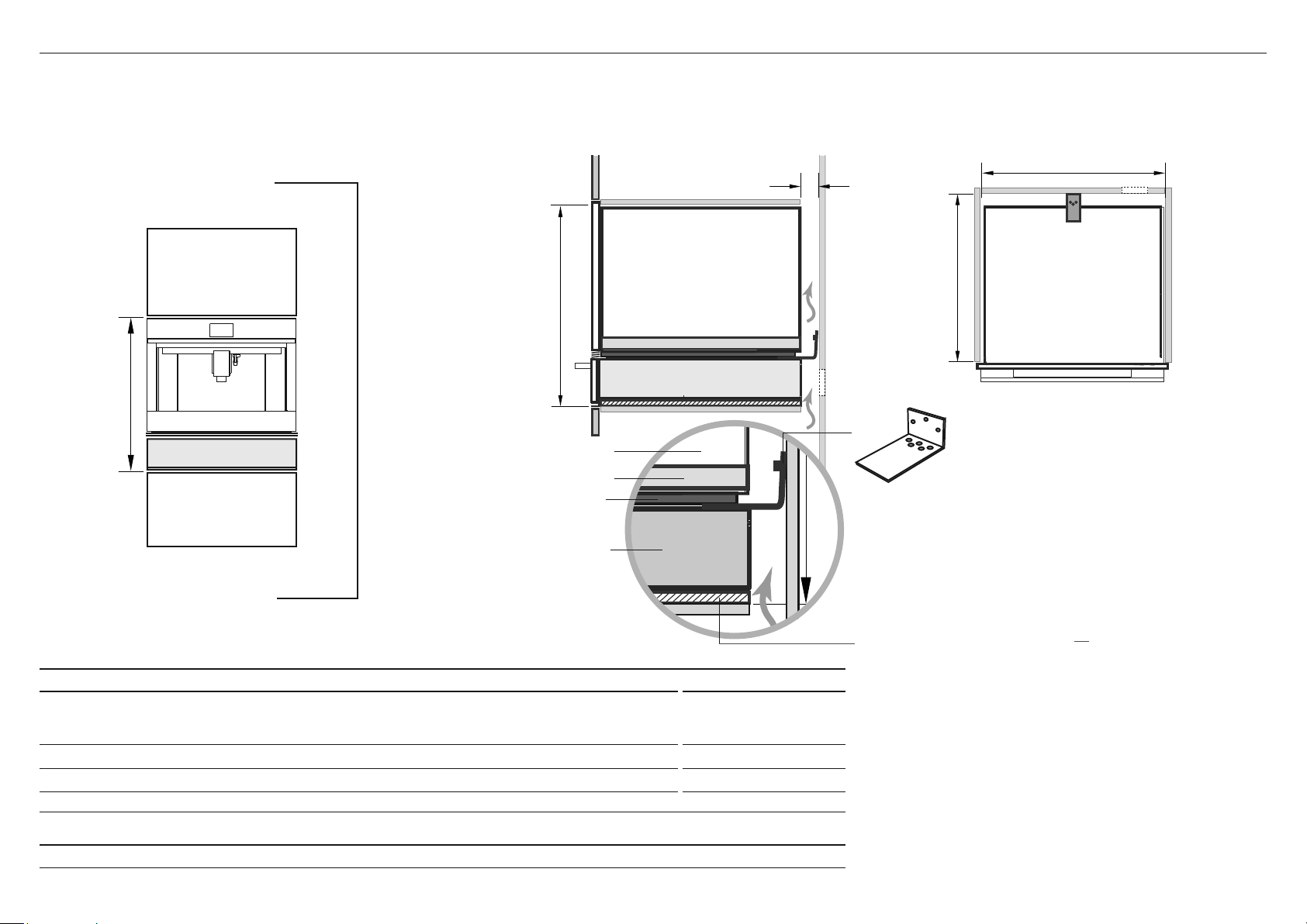
5A CABINETRY DIMENSIONS – UNDERBENCH (ie INSTALLED WITH F&P SINGLE OVEN)
**
28 3/8"
(720mm)
Warming drawer
Warming drawer
Oven
Oven
*PO
Tab
Oven support bracket
Fit the supplied oven support brackets
Unscrew-fit-
rescrew
THE FOLLOWING PAGES DETAIL COMMON CABINETRY SCENARIOS
IMPORTANT!
If installing under an oven, you must first fit the two supplied
Oven support brackets to the sides of the Warming Drawer.
The brackets help support the rear of the oven.
Unscrew the 3 top screws on each side, fit the brackets
with the tabs facing inwards as shown and screw back in.
Note: The screws may not be identical.
Replace each screw into its original hole position.
Oven support
brackets
PLAN
SIDE
CABINETRY DIMENSIONS inches (mm)
M
Minimum inside height of cavity 27" (687)
N
Inside width of cavity 22" (560)
O
Minimum inside depth of cavity 22 1/4" (565)
Note: When installed in combination with a companion product the companion product may be placed directly onto the warming drawer. It is not
necessary to place a shelf between the products. A built-in shelf at the base of the cabinetry able to support the weight of both products is required.
* PO – POWER OUTLET. Ensure there is an accessible earthed power outlet within 35 7/16" (900mm) of the centre rear of the product.
N
O
M
6 | WARMING DRAWER INSTALLATION GUIDE
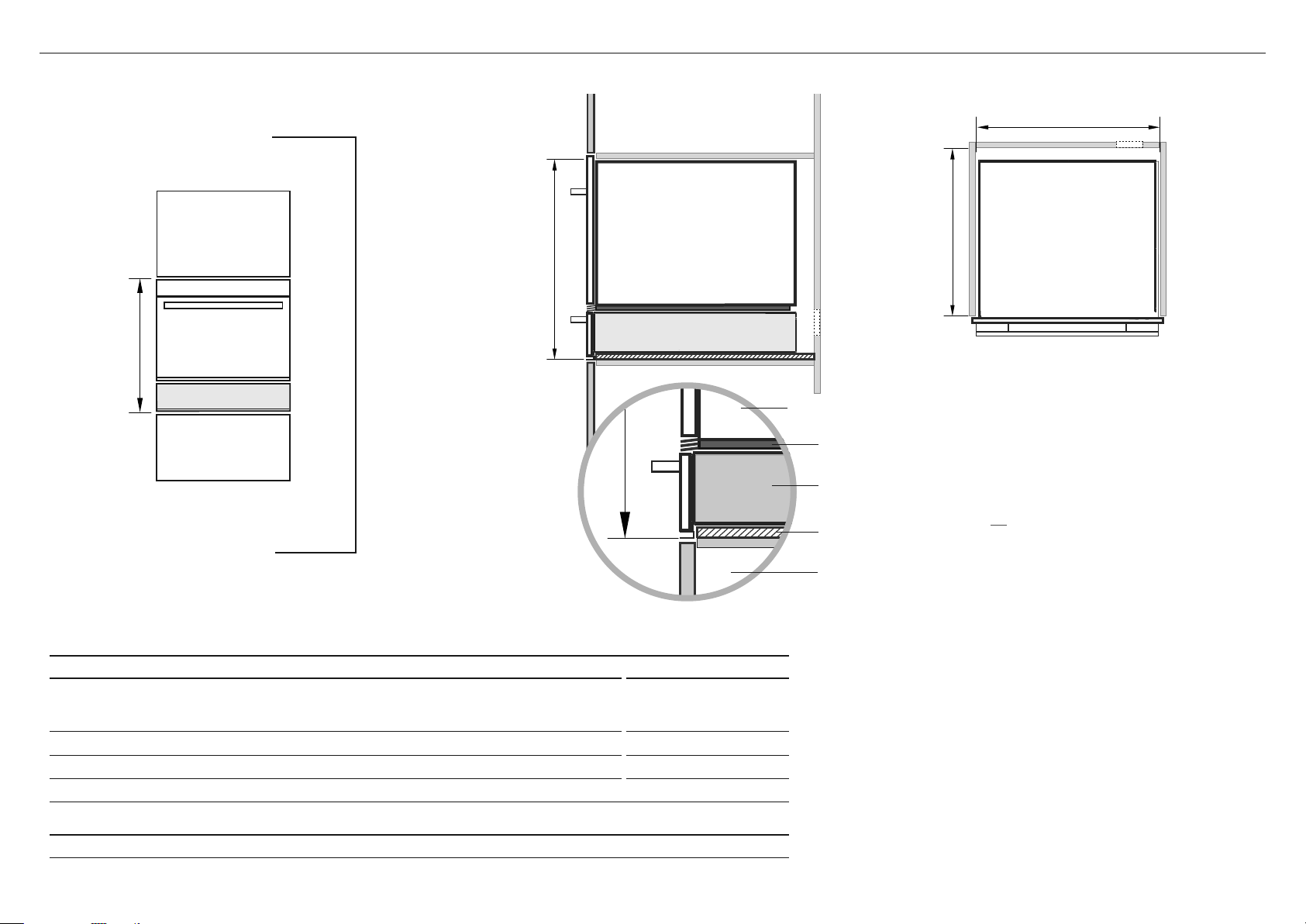
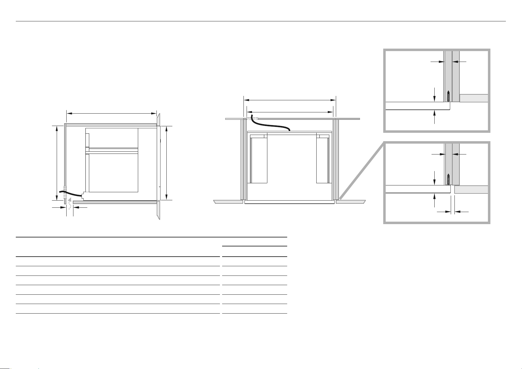
5B CABINETRY DIMENSIONS – WALL MOUNTED (ie INSTALLED WITH A F&P COMPACT OVEN)
23 5/8"
(600mm)
*PO
PLAN
SIDE
CABINETRY DIMENSIONS inches (mm)
M
Minimum inside height of cavity
with optional Lower trim kit fitted
without optional Lower trim kit fitted
23 1/4" (590)
22 1/2" (570)
N
Inside width of cavity 22" (560)
O
Minimum inside depth of cavity 22 1/4" (565)
Note: When installed in combination with a companion product the companion product may be placed directly onto the warming drawer. It is not
necessary to place a shelf between the products. A built-in shelf at the base of the cabinetry able to support the weight of both products is required.
* PO – POWER OUTLET. Ensure there is an accessible earthed power outlet within 35 7/16" (900mm) of the centre rear of the product.
Compact oven
Compact oven
Cabinet below
Additional 11/16" (18mm)
Wood Spacer
Warming drawer
Lower trim kit
(optional, supplied separately)
Compact oven
IMPORTANT!
In a wall mounted installation,
there needs to be an
11/16" (18mm) Spacer fixed
underneath the warming
drawer first to raise it to the
required height.
Warming drawer
Warming drawer
N
O
M
M

WARMING DRAWER INSTALLATION GUIDE | 7
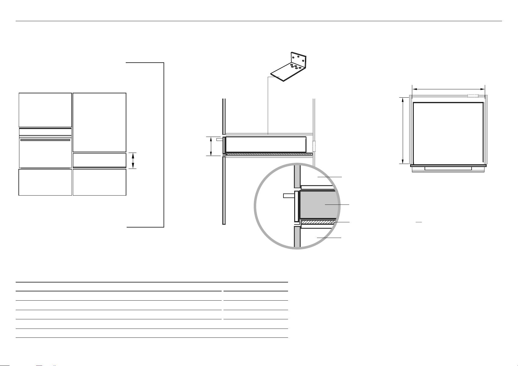
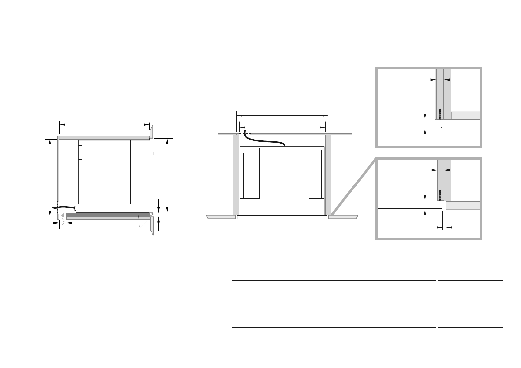
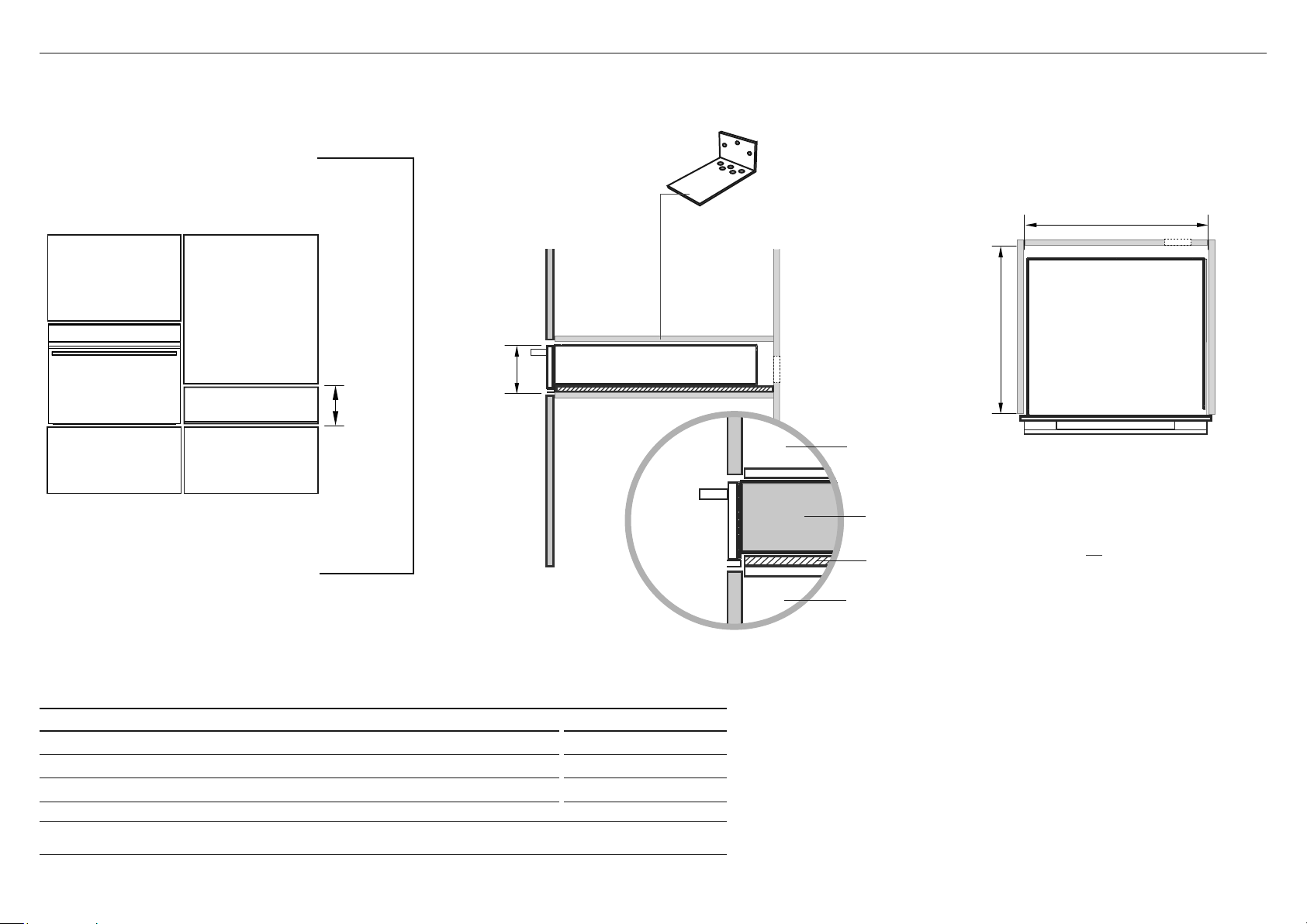
5C CABINETRY DIMENSIONS – WALL MOUNTED (ie INSTALLED WITH A F&P COFFEE MAKER)
23 5/8"
(600mm)
1 3/4"
(45mm)
*PO
PLAN
SIDE
CABINETRY DIMENSIONS inches (mm)
M
Minimum inside height of cavity
with optional Lower trim kit fitted
without optional Lower trim kit fitted
23 1/4" (590)
22 1/2" (570)
N
Inside width of cavity 22" (560)
O
Minimum inside depth of cavity 22 1/4" (565)
Note: When installed in combination with a companion product the companion product may be placed directly onto the warming drawer. It is not
necessary to place a shelf between the products. A built-in shelf at the base of the cabinetry able to support the weight of both products is required.
* PO – POWER OUTLET. Ensure there is an accessible earthed power outlet within 35 7/16" (900mm) of the centre rear of the product.
Additional 11/16" (18mm)
Wood spacer
IMPORTANT!
In a wall mounted installation,
there needs to be an
11/16" (18mm) Spacer fixed
underneath the warming
drawer first to raise it to the
required height.
Warming drawer
Warming drawer
Coffee maker
Coffee maker
Warming drawer
Lower trim kit
(optional, supplied separately)
Coffee maker
Side rail
IMPORTANT!
When installing under an F&P Coffee maker
you must ensure the supplied anti-tip
bracket is installed, unless there is a
fixed shelf above the drawer acting as
an anti-tip obstacle.
Anti-tip bracket
Supplied anti-tip bracket
(screwed to the back wall)
IMPORTANT!
If installing under the F&P Coffee Maker, ensure there
is the 2" (50mm) gap at the back of the cabinet and the
7 7/8"
2
(200mm
2
) toekick cutout required for airflow.
Refer to the Coffee Maker Install instructions.
N
O
M
M
8 | WARMING DRAWER INSTALLATION GUIDE
5D CABINETRY DIMENSIONS – WALL MOUNTED (STANDALONE)
4 3/4"
(120mm)
*PO
PLAN
SIDE
CABINETRY DIMENSIONS inches (mm)
M
Inside height of cavity
4 3/4" (120)
N
Inside width of cavity 22" (560)
O
Minimum inside depth of cavity 21 1/2" (545)
* PO – POWER OUTLET. Ensure there is an accessible earthed power outlet within 35 7/16" (900mm) of the centre rear of the product.
Additional 11/16" (18mm)
Wood spacer
IMPORTANT!
In a wall mounted installation,
there needs to be an
11/16" (18mm) Spacer fixed
underneath the warming
drawer first to raise it to
the required height.
Warming drawer
Supplied anti-tip bracket
(screwed to the back wall)
Fixed shelf
IMPORTANT!
In a standalone wall mounted installation, you
must ensure that the supplied anti-tip bracket
is installed unless there is a fixed shelf above
acting as an anti-tip obstacle.
Steam oven
Cabinet below
Cabinet above
Warming drawer
N
O
M
WARMING DRAWER INSTALLATION GUIDE | 9
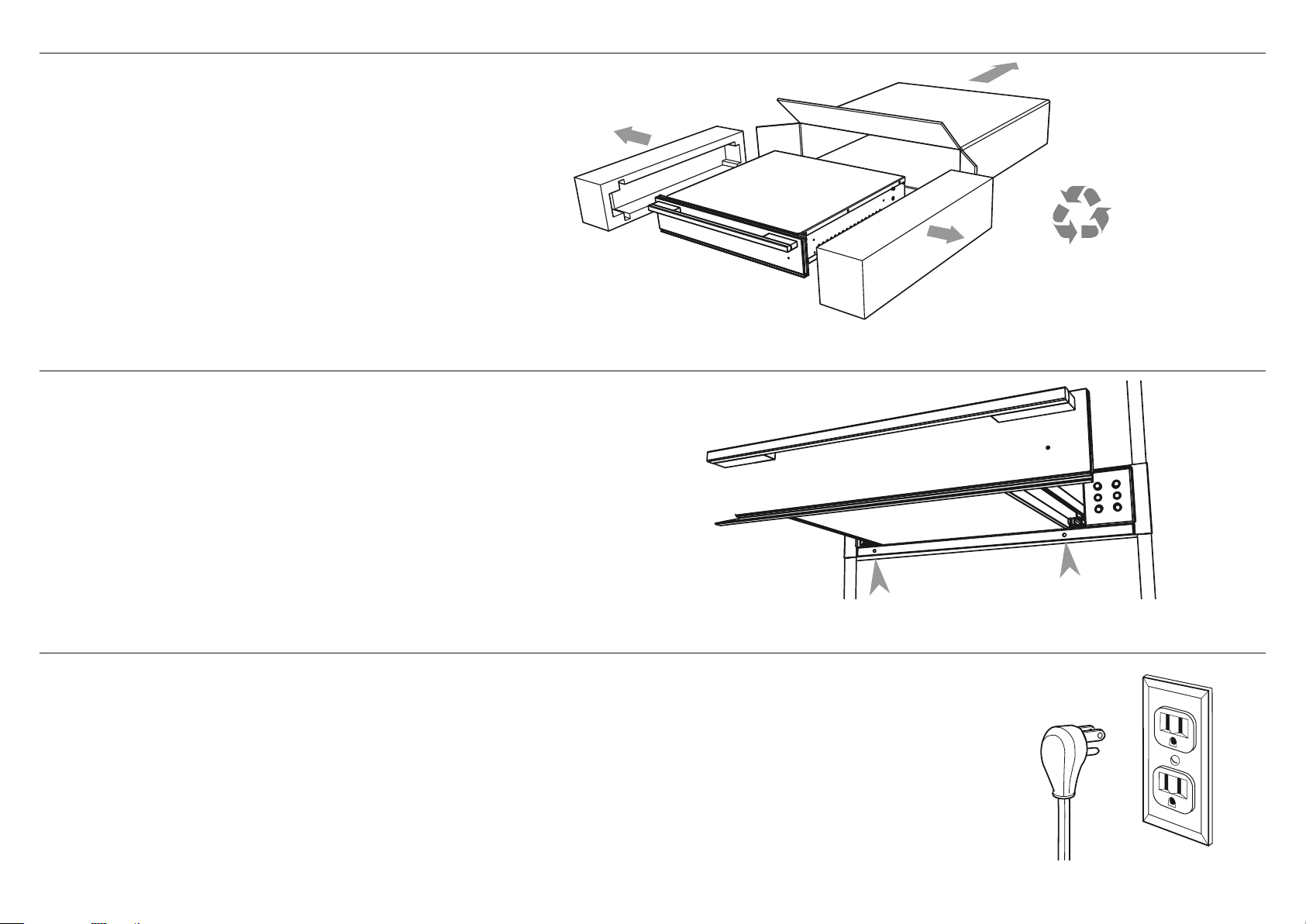
6 DISCARD PACKAGING RESPONSIBLY
7 MARK AND PRE-DRILL THE HOLES FOR SECURING THE WARMING DRAWER
8 CONNECT THE WARMING DRAWER TO THE MAINS SUPPLY
Recycle responsibly
IMPORTANT!
Do not lift the warming drawer by the drawer handle.
IMPORTANT!
●
All electrical work may only be carried out by suitably qualified and competent persons in accordance with national and local safety regulations.
●
This warming drawer must be grounded.
Before placing the warming drawer into the cavity, route the power cord into the back of the cavity and plug it in to the switched socket.
The switched socket should be in an easily accessible area within 35 7/16" (900mm) of the centre rear of the product.
Power requirements
Model code Current Voltage Wattage
WB24SDEB / WB24SDEX 4A 120V 832–960W
Unpack the warming drawer and inspect for any signs of damage.
Do not install the warming drawer if it has been damaged.
IMPORTANT!
Packing materials (eg plastic bags, polystyrene foam, staples,
packing straps etc) and tools should not be left around during
and after installation, especially if they are within easy reach
of children, as they may cause serious injuries.

10 | WARMING DRAWER INSTALLATION GUIDE
1 Ensure the warming drawer is level and positioned in place in the cavity.
IMPORTANT!
Do not lift the warming drawer by the drawer handle.
2 Fully open the drawer.
3 Fasten the warming drawer in place with the two screws supplied, through the
front trim, beneath the drawer. Do not overtighten the screws.
If the anti-tip bracket is required (see example scenarios) first secure the product at the
front, then place the bracket centrally at the back of the cavity, sitting it on the top of
the chassis. Secure it to the rear cabinet wall using the screws provided.
9 SECURE THE WARMING DRAWER TO THE CABINETRY
!0 SECURE THE ANTI-TIP BRACKET (OPTIONAL DEPENDING ON CABINETRY CONFIGURATION)

WARMING DRAWER INSTALLATION GUIDE | 11
!1 FINAL CHECKLIST
TO BE COMPLETED BY THE INSTALLER
F Make sure the warming drawer is level and securely fitted to the cabinetry.
F Make sure any internal packaging has been removed from the drawer.
F Make sure that the isolating switch is accessible by the customer.
F Make sure the anti-tip bracket has been fitted correctly if it is required.
F If installing an oven directly on top of the warming drawer, make sure the supplied oven support brackets have been fitted to the warming drawer.
TEST OPERATION:
F Open the drawer and press the
button to turn the warming drawer on.
The on/off halo and temperature setting 2 ( ) halo should glow red.
Shut the drawer.
After 5–10 minutes open the drawer. The internal surfaces of the drawer should feel slightly warmed.
Press the button to turn the warming drawer off and shut the drawer.
Complete and keep for safe reference:
Model
Serial No.
Purchase Date
Purchaser
Dealer Address
Installer’s Name
Installer’s Signature
Installation Company
Installation Date

COFFEE MAKER
EB24 models
COFFEE MAKER INSTALLATION GUIDE | 13
IMPORTANT SAFETY INSTRUCTIONS!
Installation
Checking for transport damage
After removing the packaging, make sure the product is complete and undamaged and that all
accessories are present. Do not use the appliance if it is visibly damaged. Contact Customer Care.
IMPORTANT!
●
Before connecting the appliance to the electrical supply make sure that the voltage and
frequency listed on the data plate correspond with the household electrical supply. If in
doubt, consult a qualified technician.
●
The appliance must be properly installed before operation to ensure that no electrical
components are accessible. Ensure that power is not supplied to the appliance while
installation work, repairs or maintenance is performed.
●
Be certain your appliance is properly installed and grounded by a qualified technician.
To guarantee the electrical safety of this appliance, continuity must exist between the
appliance and effective grounding system. It is imperative that this basic safety requirement
be met. If there is any doubt, have the electrical system of the house checked by a qualified
electrician. The manufacturer cannot be held responsible for damages caused by the lack,
or inadequacy, of an effective grounding system.
●
Do not use an extension cord to connect the appliance to electricity. Extension cord doesn’t
guarantee the required safety of the appliance (danger of overheating).
●
Before service or maintenance disconnect the power supply by either switching off the
main switch and unplugging the unit.
●
Install or locate this appliance only in accordance with the provided installation
instructions.
●
Installation work and repairs must be only performed by a trained technician in accordance
with national and local safety regulations. Repairs and other work by unauthorized persons
could be dangerous and may void the warranty.
●
Only use original spare parts. Only then can the manufacturer guarantee the safety of this
machine.
●
Never open the outer casing of the appliance. Tampering with electrical connections or
components and mechanical parts is dangerous and may cause machine damage.
●
If the machine is installed in combination with other appliances, a protective base should
be installed between the appliance and the unit.
●
Do not install or use outdoors even if installed in the display cabinet.
IMPORTANT!
SAVE THESE INSTRUCTIONS
1 SAFETY AND WARNINGS
WARNING!
Cut Hazard
Take care – some edges are sharp.
Failure to use caution could result in injury or cuts.
●
To protect against fire, electric shock and injury to persons do not submerge the cord or
plugs in water or other liquids.
●
To reduce the risk of injury, do not drape cord over the counter top or table top where it
can be pulled on by children or tripped over unintentionally.
●
Do not let the cord hang over the edge of a table or counter, or touch hot surfaces.
●
Do not operate any appliance with a damaged cord or plug, or after the appliance
malfunctions or has been damaged in any manner.
●
Return appliance to an authorized service facility for examination, repair or adjustment.
●
To disconnect turn the machine off, switch off the main switch then remove the plug
from the wall outlet.
●
Do not allow children and animals to stop or linger near the appliance when it is pulled
out of the cabinet.
●
Do not leave the machine pulled out of the cabinet when it is being used.
●
Do not leave the machine pulled out of the cabinet when it is not needed.
●
Install the machine according to the instructions in the handbook to guarantee there are
no spills when it is pulled out from the cabinet.
●
The rails fixing panel must have a thickness suited to the fixing screws supplied standard.
●
The panel material must be suited to the machine weight of approximately 55lb.
14 | COFFEE MAKER INSTALLATION GUIDE
2 PARTS SUPPLIED
3 PRIOR TO INSTALLATION
4 AFTER INSTALLATION
Screws
(28)
Spacers
(4) for side
(4) for bottom
●
The countertop and coffee maker cavity are square and level, and are the required dimensions.
●
The installation will comply with all clearance requirements and applicable standards and regulations.
●
The isolating switch will be easily accessible to the customer with the coffee maker installed.
●
The electrician provides sufficient free length of power supply cable to reach from the bottom rear of the cavity
to at least 59 1/16" (1.5m) in front of the bottom edge of the opening.
●
The cable may enter the cavity from the side, top or bottom, but top entry must be at the rear of the cavity.
●
The coffee maker connection socket (if fitted) is outside the cavity if the oven is flush to the rear wall.
●
The coffee maker will rest on a surface that can support its weight.
●
The height from the floor suits the customer.
●
You consult local building authorities and by-laws if in doubt regarding installation.
IMPORTANT!
Some environmental factors and cooking habits can cause condensation in and around the coffee maker during use.
To protect surrounding cabinetry from possible damage caused by frequent or excessive condensation, we recommend
moisture-proofing the cavity.
IMPORTANT!
Take extra care not to damage the lower trim of the coffee maker during installation. The trim is important for correct air circulation and allows the door to open and close without obstruction.
The manufacturer does not accept any responsibility for damage resulting from incorrect installation.
●
The coffee maker can be used fully without obstruction.
●
The power supply cable does not touch any hot metal parts.
●
The isolating switch is easily accessible to the customer with the coffee maker installed.
●
You complete the ‘Final checklist’ at the end of the installation.
●
If, after following the instructions given, correct performance cannot be achieved, please contact your nearest Fisher & Paykel Authorized Service Center, Customer Care, or
contact us through our local website listed at the end of this document.
Rails (2)
Clip (1)
Optional Trim kit installation
If you are using a 30" (762mm) trim kit, refer
to the separate Trim Kit Installation Guide.
COFFEE MAKER INSTALLATION GUIDE | 15
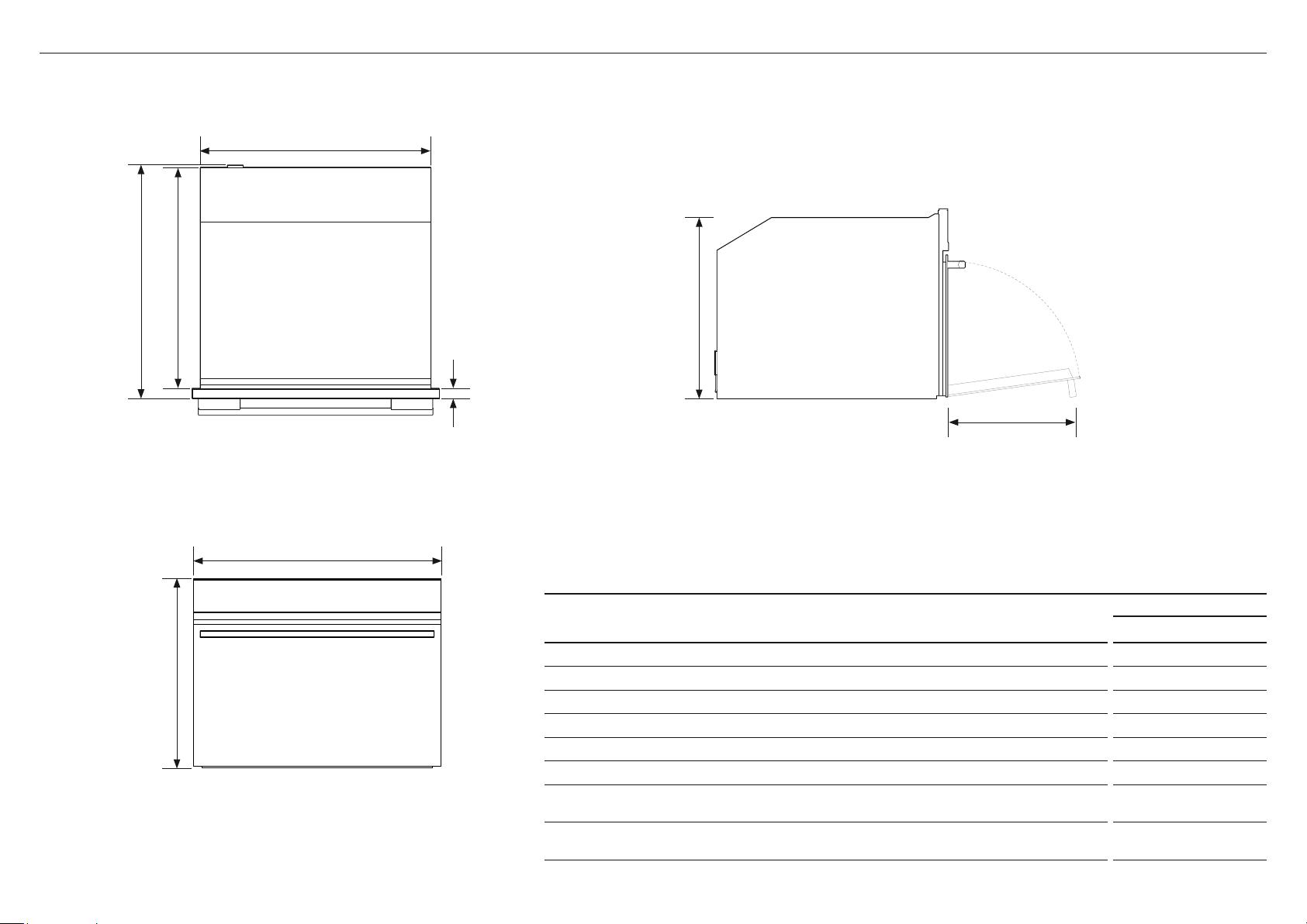
5 PRODUCT DIMENSIONS
FRONT
TOP
SIDE
PRODUCT DIMENSIONS
EB24 MODELS
inches (mm)
A
Overall height of product 18" (458)
B
Overall width of product 23 1/2" (596)
C
Overall depth of product (excluding dials) 18 7/8" (480)
D
Height of chassis 17 1/2" (445)
E
Width of chassis 22 1/16" (560)
F
Depth of chassis 18 1/8" (460)
G
Depth of coffee maker frame and control panel 13/16" (20)
H
Stepdown control panel to chassis 1/2" (13)
I
Height of control panel 4" (100)
B
E
A
C F
D
I
H
16 | COFFEE MAKER INSTALLATION GUIDE
Verify the minimum measurements required for correct installation of the appliance. The coffee maker must be
installed in a column and the column must be firmly fixed to the wall with commercially available brackets.
IMPORTANT!
●
All installation or maintenance operations must be performed with the appliance disconnected
from the mains electricity supply.
●
Kitchen furniture in direct contact with the appliance must be heat resistant 149°F min (65°C min).
●
To guarantee correct ventilation, leave a gap at the bottom of the cabinet
(see measurements below).
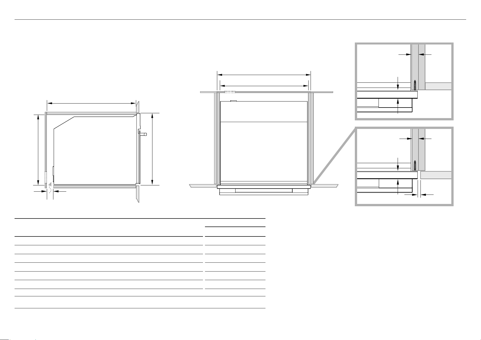
6A CABINETRY DIMENSIONS (18 1/8" (460mm) HIGH CAVITY)
PROUD INSTALL
FLUSH INSTALL
5/8–13/16"
(16–20mm)
min 1/16" (2mm)
5/8–13/16"
(16–20mm)
Electrical supply
CABINETRY DIMENSIONS
EB24 MODELS
inches (mm)
I
Minimum inside width of cavity 22 1/16" (560)
J
Overall width of cabinetry 23 5/8" (600)
K
Minimum inside height of cavity 17 3/4" (450)
L
Overall height of cabinetry 18 1/8" (460)
M
Minimum inside depth of cavity 21 7/16" (545)
n
Ventilation Air Gap 2" (50)
TOPSIDE
M
J
I
Lk
n
13/16"
(20mm)
13/16"
(20mm)
COFFEE MAKER INSTALLATION GUIDE | 17
Verify the minimum measurements required for correct installation of the appliance. The coffee maker must be
installed in a column and the column must be firmly fixed to the wall with commercially available brackets.
Lower Trim Kit
The Lower Trim kit shown is available to order separately from fisherpaykel.com.
To install the trim kit, refer to the instructions which accompany it.
IMPORTANT!
●
All installation or maintenance operations must be performed with the appliance disconnected
from the mains electricity supply.
●
Kitchen furniture in direct contact with the appliance must be heat resistant 149°F min (65°C min).
●
To guarantee correct ventilation, leave a gap at the bottom of the cabinet
(see measurements below).
6B CABINETRY DIMENSIONS (18 7/8" (480mm) CAVITY TRIM KIT)
TOPSIDE
Electrical supply
o
Lower
Trim kit
M
J
I
Lk
n
CABINETRY DIMENSIONS
EB24 MODELS
inches (mm)
I
Minimum inside width of cavity 22 1/16" (560)
J
Overall width of cabinetry 23 5/8" (600)
K
Minimum inside height of cavity 18 1/2" (470)
L
Overall height of cabinetry 18 7/8" (480)
M
Minimum inside depth of cavity 21 7/16" (545)
n
Ventilation air vent 2" (50)
o
Height of trim kit
13/16" (20)
PROUD INSTALL
FLUSH INSTALL
5/8–13/16"
(16–20mm)
min 1/16" (2mm)
5/8–13/16"
(16–20mm)
13/16"
(20mm)
13/16"
(20mm)
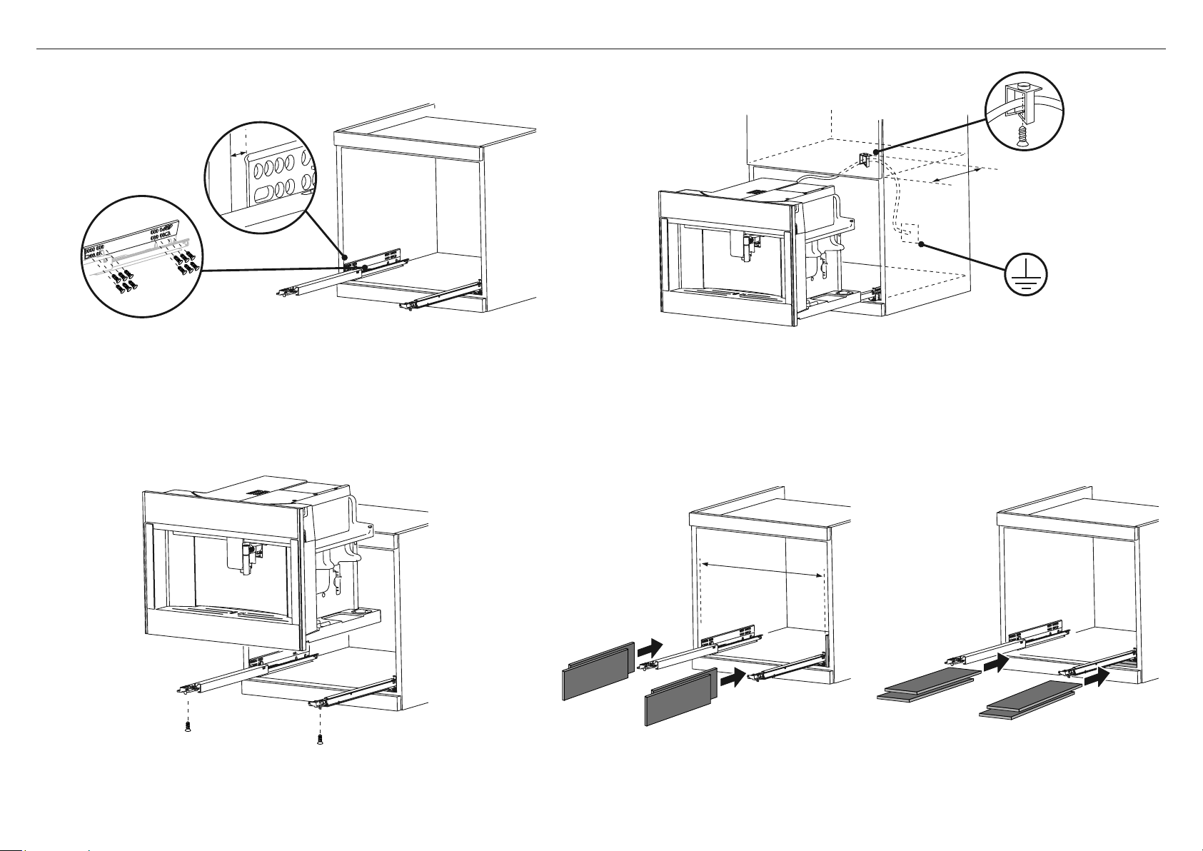
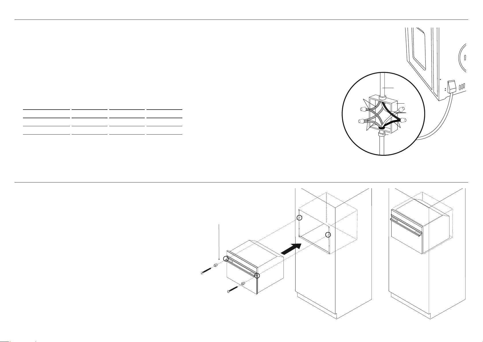
18 | COFFEE MAKER INSTALLATION GUIDE
1 Position the rails on the sides of the cabinet. Fix with the screws provided, then extract
them completely.
●
If the coffee maker is installed over a warmer drawer, use the top surface of this as
a reference to position the rails.
●
In this case, there will be no surface to rest the rails on.
2 Fix the power cable with the clip. The power cable must be long enough to allow
the appliance to be extracted from the cabinet to fill the coffee bean container.
●
The appliance must be earthed in compliance with legislation.
●
Electrical connections must be performed by a qualified electrician following
the instructions.
3 Position the appliance on the rails, making sure the pins are correctly inserted
in the housings, then fix it with the screws supplied. If the height of the appliance
requires adjusting, use the spacer disks provided.
4 If necessary, correct alignment of the appliance by positioning the spacers
supplied under or at the sides of the support.
7 INSTALLATION INSTRUCTIONS
approx. 13 3/4" (350mm)
22 1/16" min
(560mm min)
0.07"
(1.8mm)

COFFEE MAKER INSTALLATION GUIDE | 19
8 CONNECT THE WARMING DRAWER TO THE MAINS SUPPLY
IMPORTANT!
●
All electrical work may only be carried out by suitably qualified and competent persons in accordance with national and local safety regulations.
●
This warming drawer must be grounded.
Before placing the coffee maker into the cavity, route the power cord into the back of the cavity and plug it in to the switched socket.
The switched socket should be in an easily accessible area within 35 7/16" (900mm) of the centre rear of the product.
Power requirements
Model Code Power Voltage Wattage Hz
EB24 11.25 A 120 V 1350 W 60 Hz

20 | COFFEE MAKER INSTALLATION GUIDE
TO BE COMPLETED BY THE INSTALLER
F Make sure the coffee maker is level and securely fitted to the cabinetry.
F Check the lower trim is undamaged.
F Check there is adequate clearance. This is to ensure correct air circulation.
F Make sure any cable ties and internal packaging has been removed from the coffee maker cavity.
F Make sure all coffee maker vents and openings are clear and free of any obstruction or damage.
IMPORTANT!
Failure to make sure all vents are clear may result in poor product performance.
F Make sure the isolating switch is accessible by the customer.
TEST OPERATION:
F Turn the power to the coffee maker on. The display should light up.
F Have you demonstrated the basic operation to the customer?
F Fill the water tank to the indicated level.
9 FINAL CHECKLIST
Complete and keep for safe reference:
Model
Serial No.
Purchase Date
Purchaser
Dealer Address
Installer’s Name
Installer’s Signature
Installation Company
Installation Date
STEAM OVEN
OS24N models

22 | STEAM OVEN INSTALLATION GUIDE
IMPORTANT!
SAVE THESE INSTRUCTIONS
1 SAFETY AND WARNINGS
Installation
WARNING!
Fire Hazard
Do not use adapters, reducers, or branching devices to connect this
appliance to the mains power supply.
Failure to follow this advice may result in overheating, burning, or fire.
WARNING!
Cut Hazard
Take care – some edges are sharp.
Failure to use caution could result in injury or cuts.
WARNING!
Electrical Shock Hazard
Before carrying out any work on the electrical section of the appliance,
it must be disconnected from the mains electricity supply.
Connection to a good ground wiring system is absolutely essential
and mandatory.
Alterations to the domestic wiring system must only be made by a
qualified electrician
Failure to follow this advice may result in electrical shock or death.
●
If the installation requires alterations to the domestic electrical system, call a qualified
electrician. The electrician should also check that the socket cable section is suitable
for the electricity drawn by the oven.
●
The oven must be grounded.
●
Installation must comply with your local building and electricity regulations.
●
This appliance must be installed and connected to the mains power supply only by a
suitably qualified person according to these installation instructions and in compliance
with any applicable local building and electricity regulations. Failure to install the
appliance correctly could invalidate any warranty or liability claims.
●
If the power supply cable is damaged, it must be replaced by the manufacturer, its
service agent or similarly qualified person in order to avoid a hazard.
●
A circuit breaker is recommended.
●
Do not use adaptors, reducers or branching devices to connect the oven to the mains
electricity supply, as they can cause overheating and burning.
●
Make sure the cavity is completely sealed with no gaps. This is to ensure the oven
cooling system functions correctly.
●
Do not allow children and animals to stop or linger near the appliance when it is pulled
out of the cabinet.
Electrical requirements
●
Connect oven with copper wire only.
●
Do not cut the conduit.
●
A U.L. listed conduit connector must be provided at the junction box.
●
Do not ground to a gas pipe.
●
Do not have a fuse in the grounding or neutral circuit.
●
Fuse both sides of the line.
●
A time delay fuse or circuit breaker is recommended. If using a time delay fuse, then
fuse both sides of the line.
●
Flexible armored cable from the appliance should be connected directly
to the junction box.
●
Connect directly to the fused disconnect (or circuit breaker box) through flexible,
armored or non-metallic sheathed, copper cable (with grounding wire).
●
If codes permit and a separate grounding wire is used, it is recommended that a
qualified electrician determine that the grounding path and wire gauge are in
accordance with local codes.
IMPORTANT SAFETY INSTRUCTIONS!
To avoid hazard, follow these instructions carefully before installing or using this appliance.
●
Save these instructions for the local inspectors use.
●
Please make this information available to the person installing the appliance – doing
so could reduce your installation costs.
●
This oven is to be installed and connected to the electricity supply only by an
authorized person.
STEAM OVEN INSTALLATION GUIDE | 23
2 PRIOR TO INSTALLATION
3 AFTER INSTALLATION
●
The countertop and oven cavity are square and level, and are the required dimensions.
●
The installation will comply with all clearance requirements and applicable standards and regulations.
●
The isolating switch will be easily accessible to the customer with the oven installed.
●
The electrician provides sufficient free length of power supply cable to reach from the bottom rear of the cavity
to at least 59 1/16" (1.5m) in front of the bottom edge of the opening.
●
The cable may enter the cavity from the side, top or bottom, but top entry must be at the rear of the cavity.
●
The oven connection socket (if fitted) is outside the cavity if the oven is flush to the rear wall.
●
The oven will rest on a surface that can support its weight.
●
The height from the floor suits the customer.
●
You consult local building authorities and by-laws if in doubt regarding installation.
IMPORTANT!
Some environmental factors and cooking habits can cause condensation in and around the oven during use.
To protect surrounding cabinetry from possible damage caused by frequent or excessive condensation, we
recommend moisture-proofing the oven cavity.
IMPORTANT!
Take extra care not to damage the lower trim of the oven during installation. The trim is important for correct air circulation and allows the door to open and close without obstruction.
The manufacturer does not accept any responsibility for damage resulting from incorrect installation.
●
The oven door(s) can open fully without obstruction.
●
The power supply cable does not touch any hot metal parts.
●
The isolating switch is easily accessible to the customer with the oven installed.
●
You complete the ‘Final checklist’ at the end of the installation.
●
If, after following the instructions given, correct performance cannot be achieved, please contact your nearest Fisher & Paykel Authorized Service Center, Customer Care, or
contact us through our local website listed at the end of this document.
Optional Trim kit installation
If you are using a 30" (762mm) trim kit, refer
to the separate Trim Kit Installation Guide.

24 | STEAM OVEN INSTALLATION GUIDE
4 PRODUCT DIMENSIONS
PRODUCT DIMENSIONS
OS24N MODELS
inches (mm)
A
Overall height of product 18" (458)
B
Overall width of product 23 7/16" (596)
C
Overall depth of product (excluding handle and dials) 22 1/8" (562)
D
Height of chassis 17 1/2" (445)
E
Width of chassis 21 7/8" (556)
F
Depth of chassis 21 1/4" (540)
G
Depth of oven frame and control panel
(=distance between front of chassis and front of oven door, excl. knobs)
7/8" (22)
H
Depth of oven door when fully open
(measured from front of control panel)
12 5/8" (320)
FRONT
TOP SIDE
B
E
A
C F
G
D
H
STEAM OVEN INSTALLATION GUIDE | 25
TOPSIDE
CABINETRY DIMENSIONS
OS24N MODELS
inches (mm)
I
Minimum inside width of cavity 22 1/16" (560)
J
Overall width of cabinetry 23 5/8" (600)
K
Minimum inside height of cavity 17 3/4" (450)
L
Overall height of cabinetry 18 1/8" (460)
M
Minimum inside depth of cavity 22 1/16" (560)
n
Ventilation air vent
2" (50)
Note: If installing a cooktop above the oven, ensure adequate clearance is provided for the cooktop as per the cooktop
manufacturer’s instructions.
5A CABINETRY DIMENSIONS (18 1/8" (460mm) HIGH CAVITY)
●
The oven can be installed under a cooktop, in a column, or combined with the companion warmer drawer.
●
The cabinet material must be able to withstand heat.
●
The oven must be centered within the walls of the cabinet and fixed with the screws and bushings that are provided.
Electrical supply
M
J
I
Lk
n
PROUD INSTALL
FLUSH INSTALL
5/8–13/16"
(16–20mm)
min 1/16" (2mm)
5/8–13/16"
(16–20mm)
7/ 8"
(22mm)
7/ 8"
(22mm)
26 | STEAM OVEN INSTALLATION GUIDE
TOPSIDE
CABINETRY DIMENSIONS
OS24N MODELS
inches (mm)
I
Minimum inside width of cavity 22 1/16" (560)
J
Overall width of cabinetry 23 5/8" (600)
K
Minimum inside height of cavity 18 1/2" (470)
L
Overall height of cabinetry 18 7/8" (480)
M
Minimum inside depth of cavity 22 1/16" (560)
n
Ventilation air vent 2" (50)
o
Height of trim kit
13/16" (20)
Note: If installing a cooktop above the oven, ensure adequate clearance is provided for the cooktop as per the cooktop
manufacturer’s instructions.
5B CABINETRY DIMENSIONS (18 7/8" (480mm) CAVITY TRIM KIT)
●
The oven must be installed under a cook top, in a column, or combined with the companion warmer drawer.
●
The cabinet material must be able to withstand heat.
●
The oven must be centred within the walls of the cabinet and fixed with the screws and bushings that are provided.
Lower Trim Kit
The Lower Trim kit shown is available to order separately from fisherpaykel.com.
To install the trim kit, refer to the instructions which accompany it.
Electrical supply
o
Lower
Trim kit
M
J
I
Lk
n
PROUD INSTALL
FLUSH INSTALL
5/8–13/16"
(16–20mm)
min 1/16" (2mm)
5/8–13/16"
(16–20mm)
7/ 8"
(22mm)
7/ 8"
(22mm)

STEAM OVEN INSTALLATION GUIDE | 27
7 SECURE THE OVEN TO THE CABINETRY
1 Position the oven in the prepared cavity.
IMPORTANT!
Do not lift the oven by the door handle.
2 Use the supplied screws and spacers to secure the oven
to the cabinetry.
IMPORTANT!
●
Do not over-tighten the screws.
●
Take care not to damage the lower trim of the oven.
●
Do not seal the oven into the cabinetry with silicone or glue.
This makes future servicing difficult. Fisher & Paykel will not cover
the costs of removing the oven, or of damage caused by this removal.
Ensure supplied spacer
is fitted between oven
and cabinetry
Before connecting to the electricity, make sure that the:
●
specifications of the electrical system match with what is detailed on this section. (Fig. 1)
●
system has an effective ground connection compliant with current standards and laws.
The ground connection is required by law. The cable must not, at any point, reach a temperature greater than 122°F (50°C)
above room temperature.
This oven must be connected to the electricity through a power supply cable and plug that is compatible with the outlet
of the electrical system that powers this oven. If a fixed appliance does not have a power cord and plug, or another device
that ensures disconnection from the mains, with an opening distance of the contacts that allows complete disconnection,
such disconnection devices must be provided in the power supply mains conforming to the installation rules.
The omnipolar socket or switch must be easy to reach when the appliance is installed.
NOTE: The manufacturer declines all liability if the usual accident prevention standards and the above instructions are not followed.
6 ELECTRICAL HOOK-UP
MAX POWER (W) HZ VOLTAGE (V) AMPS (A)
3000 60 Hz 240V 12.5
2250 60 Hz 208V 10.8
UL - listed conduit
connector
wall wiring
box
cable from
power supply
white wires
red wires
green grounding
oven wires -
factory taped
black wires
Fig. 1

28 | STEAM OVEN INSTALLATION GUIDE
8 FINAL CHECKLIST
TO BE COMPLETED BY THE INSTALLER
F Make sure the oven is level and securely fitted to the cabinetry.
F Check the lower trim is undamaged.
F Open the oven door slowly until it is fully open and check there is adequate clearance between the bottom of the door and the lower trim.
This is to ensure correct air circulation. Should the lower trim become damaged, straighten the trim and ensure the oven door opens fully without obstruction.
F Make sure any cable ties and internal packaging has been removed from the oven cavity.
F Make sure all oven vents and openings are clear and free of any obstruction or damage.
IMPORTANT!
Failure to make sure all oven vents are clear may result in poor product performance.
F Make sure the isolating switch is accessible by the customer.
TEST OPERATION:
F Have you demonstrated the basic operation to the customer?
Refer to User Guide.
Complete and keep for safe reference:
Model
Serial No.
Purchase Date
Purchaser
Dealer Address
Installer’s Name
Installer’s Signature
Installation Company
Installation Date
FISHERPAYKEL.COM
© Fisher and Paykel Appliances 2020. All rights reserved.
The appliance specifications in this document apply to the specific
appliances and models described at the date of issue. Under our policy
of continuous appliance improvement, these specifications may change
at any time. You should therefore check with your Dealer to ensure this
document correctly describes the appliance currently available.
For current details about model and specification availability in your
country, go to our website fisherpaykel.com or contact your local
Fisher&Paykel dealer.

SPEED OVEN
OM24N models
30 | SPEED OVEN INSTALLATION GUIDE
IMPORTANT!
SAVE THESE INSTRUCTIONS
1 SAFETY AND WARNINGS
Installation
WARNING!
Fire Hazard
Do not use adapters, reducers, or branching devices to connect this
appliance to the mains power supply.
Failure to follow this advice may result in overheating, burning, or fire.
WARNING!
Cut Hazard
Take care – some edges are sharp.
Failure to use caution could result in injury or cuts.
WARNING!
Electrical Shock Hazard
Before carrying out any work on the electrical section of the appliance,
it must be disconnected from the mains electricity supply.
Connection to a good ground wiring system is absolutely essential
and mandatory.
Alterations to the domestic wiring system must only be made by a
qualified electrician
Failure to follow this advice may result in electrical shock or death.
●
If the installation requires alterations to the domestic electrical system, call a qualified
electrician. The electrician should also check that the socket cable section is suitable
for the electricity drawn by the oven.
●
The oven must be grounded.
●
Installation must comply with your local building and electricity regulations.
●
This appliance must be installed and connected to the mains power supply only by a
suitably qualified person according to these installation instructions and in compliance
with any applicable local building and electricity regulations. Failure to install the
appliance correctly could invalidate any warranty or liability claims.
●
If the power supply cable is damaged, it must be replaced by the manufacturer, its
service agent or similarly qualified person in order to avoid a hazard.
●
A circuit breaker is recommended.
●
Do not use adaptors, reducers or branching devices to connect the oven to the mains
electricity supply, as they can cause overheating and burning.
●
Make sure the cavity is completely sealed with no gaps. This is to ensure the oven
cooling system functions correctly.
●
Do not allow children and animals to stop or linger near the appliance when it is pulled
out of the cabinet.
Electrical requirements
●
Connect oven with copper wire only.
●
Do not cut the conduit.
●
A U.L. listed conduit connector must be provided at the junction box.
●
Do not ground to a gas pipe.
●
Do not have a fuse in the grounding or neutral circuit.
●
Fuse both sides of the line.
●
A time delay fuse or circuit breaker is recommended. If using a time delay fuse, then
fuse both sides of the line.
●
Flexible armored cable from the appliance should be connected directly
to the junction box.
●
Connect directly to the fused disconnect (or circuit breaker box) through flexible,
armored or non-metallic sheathed, copper cable (with grounding wire).
●
If codes permit and a separate grounding wire is used, it is recommended that a
qualified electrician determine that the grounding path and wire gauge are in
accordance with local codes.
IMPORTANT SAFETY INSTRUCTIONS!
To avoid hazard, follow these instructions carefully before installing or using this appliance.
●
Save these instructions for the local inspectors use.
●
Please make this information available to the person installing the appliance – doing
so could reduce your installation costs.
●
This oven is to be installed and connected to the electricity supply only by an
authorized person.

SPEED OVEN INSTALLATION GUIDE | 31
2 PRIOR TO INSTALLATION
3 AFTER INSTALLATION
●
The countertop and oven cavity are square and level, and are the required dimensions.
●
The installation will comply with all clearance requirements and applicable standards and regulations.
●
The isolating switch will be easily accessible to the customer with the oven installed.
●
The electrician provides sufficient free length of power supply cable to reach from the bottom rear of the cavity
to at least 59 1/16" (1.5m) in front of the bottom edge of the opening.
●
The cable may enter the cavity from the side, top or bottom, but top entry must be at the rear of the cavity.
●
The oven connection socket (if fitted) is outside the cavity if the oven is flush to the rear wall.
●
The oven will rest on a surface that can support its weight.
●
The height from the floor suits the customer.
●
You consult local building authorities and by-laws if in doubt regarding installation.
IMPORTANT!
Some environmental factors and cooking habits can cause condensation in and around the oven during use.
To protect surrounding cabinetry from possible damage caused by frequent or excessive condensation, we
recommend moisture-proofing the oven cavity.
IMPORTANT!
Take extra care not to damage the lower trim of the oven during installation. The trim is important for correct air circulation and allows the door to open and close without obstruction.
The manufacturer does not accept any responsibility for damage resulting from incorrect installation.
●
The oven door(s) can open fully without obstruction.
●
The power supply cable does not touch any hot metal parts.
●
The isolating switch is easily accessible to the customer with the oven installed.
●
You complete the ‘Final checklist’ at the end of the installation.
●
If, after following the instructions given, correct performance cannot be achieved, please contact your nearest Fisher & Paykel Authorized Service Center, Customer Care, or
contact us through our local website listed at the end of this document.
Optional Trim kit installation
If you are using a 30" (762mm) trim kit, refer
to the separate Trim Kit Installation Guide.
32 | SPEED OVEN INSTALLATION GUIDE
4 PRODUCT DIMENSIONS
PRODUCT DIMENSIONS
OM24N MODELS
inches (mm)
A
Overall height of product 18" (458)
B
Overall width of product 23 7/16" (596)
C
Overall depth of product (excluding handle and dials) 22 1/8" (562)
D
Height of chassis 17 1/2" (445)
E
Width of chassis 21 7/8" (556)
F
Depth of chassis 21 1/4" (540)
G
Depth of oven frame and control panel
(=distance between front of chassis and front of oven door, excl. knobs)
7/8" (22)
H
Depth of oven door when fully open
(measured from front of control panel)
12 5/8" (320)
FRONT
TOP SIDE
B
E
A
C F
G
D
H

SPEED OVEN INSTALLATION GUIDE | 33
TOPSIDE
CABINETRY DIMENSIONS
OM24N MODELS
inches (mm)
I
Minimum inside width of cavity 22 1/16" (560)
J
Overall width of cabinetry 23 5/8" (600)
K
Minimum inside height of cavity 17 3/4" (450)
L
Overall height of cabinetry 18 1/8" (460)
M
Minimum inside depth of cavity 22 1/16" (560)
n
Ventilation air vent
2" (50)
Note: If installing a cooktop above the oven, ensure adequate clearance is provided for the cooktop as per the cooktop
manufacturer’s instructions.
5A CABINETRY DIMENSIONS (18 1/8" (460mm) HIGH CAVITY)
●
The oven can be installed under a cooktop, in a column, or combined with the companion warmer drawer.
●
The cabinet material must be able to withstand heat.
●
The oven must be centered within the walls of the cabinet and fixed with the screws and bushings that are provided.
Electrical supply
M
J
I
Lk
n
PROUD INSTALL
FLUSH INSTALL
5/8–13/16"
(16–20mm)
min 1/16" (2mm)
5/8–13/16"
(16–20mm)
7/ 8"
(22mm)
7/ 8"
(22mm)

34 | SPEED OVEN INSTALLATION GUIDE
TOPSIDE
CABINETRY DIMENSIONS
OM24N MODELS
inches (mm)
I
Minimum inside width of cavity 22 1/16" (560)
J
Overall width of cabinetry 23 5/8" (600)
K
Minimum inside height of cavity 18 1/2" (470)
L
Overall height of cabinetry 18 7/8" (480)
M
Minimum inside depth of cavity 22 1/16" (560)
n
Ventilation air vent 2" (50)
o
Height of trim kit
13/16" (20)
Note: If installing a cooktop above the oven, ensure adequate clearance is provided for the cooktop as per the cooktop
manufacturer’s instructions.
5B CABINETRY DIMENSIONS (18 7/8" (480mm) CAVITY TRIM KIT)
●
The oven must be installed under a cook top, in a column, or combined with the companion warmer drawer.
●
The cabinet material must be able to withstand heat.
●
The oven must be centred within the walls of the cabinet and fixed with the screws and bushings that are provided.
Lower Trim Kit
The Lower Trim kit shown is available to order separately from fisherpaykel.com.
To install the trim kit, refer to the instructions which accompany it.
Electrical supply
o
Lower
Trim kit
M
J
I
Lk
n
PROUD INSTALL
FLUSH INSTALL
5/8–13/16"
(16–20mm)
min 1/16" (2mm)
5/8–13/16"
(16–20mm)
7/ 8"
(22mm)
7/ 8"
(22mm)
SPEED OVEN INSTALLATION GUIDE | 35
7 SECURE THE OVEN TO THE CABINETRY
1 Position the oven in the prepared cavity.
IMPORTANT!
Do not lift the oven by the door handle.
2 Use the supplied screws and spacers to secure the oven
to the cabinetry.
IMPORTANT!
●
Do not over-tighten the screws.
●
Take care not to damage the lower trim of the oven.
●
Do not seal the oven into the cabinetry with silicone or glue.
This makes future servicing difficult. Fisher & Paykel will not cover
the costs of removing the oven, or of damage caused by this removal.
Ensure supplied spacer
is fitted between oven
and cabinetry
Before connecting to the electricity, make sure that the:
●
specifications of the electrical system match with what is detailed on this section. (Fig. 1)
●
system has an effective ground connection compliant with current standards and laws.
The ground connection is required by law. The cable must not, at any point, reach a temperature greater than 122°F (50°C)
above room temperature.
This oven must be connected to the electricity through a power supply cable and plug that is compatible with the outlet
of the electrical system that powers this oven. If a fixed appliance does not have a power cord and plug, or another device
that ensures disconnection from the mains, with an opening distance of the contacts that allows complete disconnection,
such disconnection devices must be provided in the power supply mains conforming to the installation rules.
The omnipolar socket or switch must be easy to reach when the appliance is installed.
NOTE: The manufacturer declines all liability if the usual accident prevention standards and the above instructions are not followed.
6 ELECTRICAL HOOK-UP
UL - listed conduit
connector
wall wiring
box
cable from
power supply
white wires
red wires
green grounding
oven wires -
factory taped
black wires
Fig. 1
MAX POWER (W) HZ VOLTAGE (V) AMPS (A)
3400 60 Hz 120/240 14
2700 60 Hz 120/208 13

36 | SPEED OVEN INSTALLATION GUIDE
8 FINAL CHECKLIST
TO BE COMPLETED BY THE INSTALLER
F Make sure the oven is level and securely fitted to the cabinetry.
F Check the lower trim is undamaged.
F Open the oven door slowly until it is fully open and check there is adequate clearance between the bottom of the door and the lower trim.
This is to ensure correct air circulation. Should the lower trim become damaged, straighten the trim and ensure the oven door opens fully without obstruction.
F Make sure any cable ties and internal packaging has been removed from the oven cavity.
F Make sure all oven vents and openings are clear and free of any obstruction or damage.
IMPORTANT!
Failure to make sure all oven vents are clear may result in poor product performance.
F Make sure the isolating switch is accessible by the customer.
TEST OPERATION:
F Have you demonstrated the basic operation to the customer?
Refer to User Guide.
Complete and keep for safe reference:
Model
Serial No.
Purchase Date
Purchaser
Dealer Address
Installer’s Name
Installer’s Signature
Installation Company
Installation Date
FISHERPAYKEL.COM
© Fisher and Paykel Appliances 2020. All rights reserved.
The appliance specifications in this document apply to the specific
appliances and models described at the date of issue. Under our policy
of continuous appliance improvement, these specifications may change
at any time. You should therefore check with your Dealer to ensure this
document correctly describes the appliance currently available.
For current details about model and specification availability in your
country, go to our website fisherpaykel.com or contact your local
Fisher&Paykel dealer.

GUIDE D’INSTALLATION
US CA
591496F 08.20
PRODUITS COMPAGNONS
Modèles
Tiroir chauant WB24
Machine à café EB24
Four à vapeur OS24N
Four à micro-ondes OM24N

TABLE DES MATIÈRES
IMPORTANT!
CONSERVEZ CES INSTRUCTIONS
Tiroir chauffant 1
1 Sécurité et avertissements 2
2 Pièces fournies 3
3 Avant l’installation 3
4 Dimensions du produit 4
5A Dimensions de l’armoire – underbench
(ie installé avec f&p four unique) 5
5B Dimensions de l’armoire – mural
(ie installé avec un four compact F&P) 6
5C Dimensions de l’armoire – mural
(ie installé avec une cafetière F&P) 7
5D Dimensions de l’armoire – mural (standalone) 8
6 Jeter l’emballage de manière responsable 9
7 Marquer et pré-percer les trous pour fixer
le tiroir-réchaud 9
8 Connectez le tiroir chauffant à l’alimentation secteur 9
9 Fixez le tiroir chauffant aux armoires 10
10 Fixez le support anti-basculement (en option
en fonction de la configuration de l’armoire) 10
11 Liste de contrôle finale 11
Machine à café 12
1 Sécurité et avertissements 13
2 Pièces fournies 14
3 Avant l’installation 14
4 Après l’installation 14
5 Dimensions du produit 15
6A Dimensions de l’armoire
(cavité de 18 1/8" (460mm) de hauteur) 16
6B Dimensions de l’armoire
(kit de garniture de cavité de 18 7/8" (480mm)) 17
7 Instructions d’installation 18
8 Liste de contrôle finale 19
Four à vapeur 20
1 Sécurité et avertissements 21
2 Avant l’installation 22
3 Après l’installation 22
4 Dimensions du Produit 23
5A Dimensions de l’armoire
(cavité de 18 1/8" (460mm) de hauteur) 24
5B Dimensions de l’armoire
(kit de garniture de cavité de 18 7/8" (480mm)) 25
6 Branchement électrique 26
7 Fixez le four aux armoires 26
8 Liste de contrôle finale 27
Four à micro-ondes 28
1 Sécurité et avertissements 29
2 Avant l’installation 30
3 Après l’installation 30
4 Dimensions du Produit 31
5A Dimensions de l’armoire
(cavité de 18 1/8" (460mm) de hauteur) 32
5B Dimensions de l’armoire
(kit de garniture de cavité de 18 7/8" (480mm)) 33
6 Branchement électrique 34
7 Fixez le four aux armoires 34
8 Liste de contrôle finale 35
TIROIR CHAUFFANT
Modèles WB24
2 | TIROIR CHAUFFANT GUIDE D’INSTALLATION
IMPORTANT!
CONSERVEZ CES INSTRUCTIONS
1 SÉCURITÉ ET AVERTISSEMENTS
●
Avant l’installation, assurez-vous que la tension et la fréquence indiquées sur la plaque
signalétique correspondent à l’alimentation électrique domestique.
●
La prise électrique doit être facilement accessible après l’installation.
●
Lorsqu’un produit complémentaire est installé en même temps que le tiroir chauffant sur le
même circuit, l’utilisation des deux produits peut provoquer une surcharge. En cas de doute,
consultez un électricien qualifié.
●
Lorsqu’il est installé en combinaison avec un produit compagnon, le produit compagnon peut
être placé directement sur le tiroir-réchaud. Il n’est pas nécessaire de placer une étagère entre
les produits. Une étagère intégrée à la base des armoires pouvant supporter le poids des deux
produits est requise.
●
Si vous installez le tiroir-réchaud directement sous un four, veillez à ne pas endommager la
garniture inférieure du four. La garniture inférieure assure une circulation d’air correcte dans le four
et permet à la porte de s’ouvrir et de se fermer sans obstruction. Fisher & Paykel n’accepte aucune
responsabilité pour tout dommage résultant d’une installation incorrecte.
●
Le poids maximum que le tiroir chauffant peut supporter est de 132 lb (60 kg).
●
Le tiroir-réchaud n’est pas conçu pour être utilisé dans des installations mobiles telles que des
véhicules récréatifs, des bateaux ou des avions.
●
Lors de l’installation de produits d’accompagnement, le poids du produit d’accompagnement
doit être réparti sur les bords du tiroir-réchaud. Les produits au-dessus desquels reposent les
"pieds" ne peuvent être installés que si les pieds du produit se trouvent à moins de 2 3/4" (70mm)
des côtés du tiroir-réchaud, car cette zone est renforcée. Si vous ne le faites pas, vous risquez
d’endommager le tiroir-réchaud et le produit associé.
●
Avant d’installer le tiroir-réchaud, vous devez l’inspecter pour déceler tout signe de dommage.
Vous ne devez en aucun cas installer ou utiliser le tiroir chauffant s’il a été endommagé.
●
Si le cordon d’alimentation est endommagé, il doit être remplacé par le fabricant, son agent de
service ou un professionnel qualifié afin d’éviter tout danger.
●
Connecter le tiroir chauffant à un circuit d’alimentation correctement dimensionné, protégé et
dimensionné pour éviter une surcharge électrique.
●
N’utilisez pas une rallonge ou un appareil de prise de courant portatif (par exemple, une prise
de courant à plusieurs prises) pour raccorder le tiroir-réchaud à l’alimentation électrique.
Assurez-vous que le cordon d’alimentation est situé de façon à ne pas marcher, trébucher ou
subir des dommages ou des contraintes.
●
Assurez-vous que la connexion à l’alimentation est accessible après l’installation.
CONSIGNES DE SÉCURITÉ IMPORTANTES
Pour réduire les risques d’incendie, d’électrocution, de blessure ou de dommages lors de
l’utilisation du tiroir-réchaud, veuillez lire attentivement ces instructions avant d’installer ce
produit.
●
Veuillez mettre cette information à la disposition de la personne qui installe le produit – cela
pourrait réduire les coûts d’installation.
●
Les travaux d’installation, d’entretien et de réparation ne doivent être effectués que par des
personnes qualifiées et compétentes, conformément aux normes de sécurité nationales et locales.
●
Débranchez toujours l’alimentation électrique avant d’effectuer toute opération d’installation,
d’entretien ou de réparation.
AVERTISSEMENT!
Couper le danger
Attention – certains bords sont coupants.
Ne pas faire preuve de prudence peut entraîner des blessures ou des
coupures.
AVERTISSEMENT!
Risque d’incendie
N’utilisez pas d’adaptateurs, de réducteurs ou de dispositifs de
dérivation pour raccorder cet appareil à l’alimentation secteur.
Le non-respect de ce conseil peut entraîner une surchauffe, une brûlure
ou un incendie.
AVERTISSEMENT!
Danger de choc électrique
Avant d’effectuer tout travail sur la partie électrique de l’appareil,
celui-ci doit être déconnecté du secteur.
La connexion à un bon système de mise à la terre est absolument
essentielle et obligatoire.
Les modifications apportées au système de câblage domestique ne
doivent être effectuées que par un électricien qualifié.
Le non-respect de ce conseil peut entraîner un choc électrique ou la mort.
TIROIR CHAUFFANT GUIDE D’INSTALLATION | 3
3 AVANT L’INSTALLATION
●
La cavité est carrée et de niveau, et des dimensions requises.
●
L’installation sera conforme à toutes les exigences de dégagement et aux normes et règlements applicables.
●
L’interrupteur d’alimentation sera facilement accessible au client lorsque le tiroir-réchaud est installé.
●
Le tiroir chauffant (et tout produit sur le dessus) reposera sur une surface qui peut supporter son poids.
●
La hauteur du sol convient au client.
●
Vous consultez les autorités locales de construction et les règlements en cas de doute concernant l’installation.
Si l’installation avec un produit compagnon
IMPORTANT!
●
Si vous installez un produit d’accompagnement, veuillez vous reporter aux instructions d’installation de ce produit pour vous assurer que les exigences
d’installation des DEUX produits sont respectées.
●
Lors de l’installation de produits sur le dessus du tiroir-réchaud, le poids du produit doit être réparti sur les bords du tiroir-réchaud.
●
Les produits au-dessus desquels reposent les "pieds" ne peuvent être installés que si les pieds du produit se trouvent à moins de 2 3/4" (70mm) des côtés du
tiroir-réchaud, car cette zone est renforcée. Si vous ne le faites pas, vous risquez d’endommager le tiroir-réchaud et le produit associé.
Des vis (4) Support anti-basculement (1) Supports de support de four (2)
Le tiroir-réchaud peut supporter un poids
maximum de 132 lb (60 kg)
2 3/4"
(70mm)
2 3/4"
(70mm)
Pieds
2 PIÈCES FOURNIES
4 | TIROIR CHAUFFANT GUIDE D’INSTALLATION
4 DIMENSIONS DU PRODUIT
HAUT
AVANT
Bornier
LE CÔTÉ
DIMENSIONS DU PRODUIT
MODÈLE
WB24SDEB
MODÈLE
WB24SDEX
Pouces (mm) Pouces (mm)
A
Hauteur totale du produit 4 5/8" (118) 4 5/8" (118)
B
Largeur totale du produit 23 1/2" (596) 23 1/2" (596)
C
Profondeur du panneau avant du tiroir (à l’exclusion de la poignée)* 13/16" (20) 7/8" (22)
D
Profondeur du châssis (y compris le bornier) 21 1/8" (536) 21 1/8" (536)
E
Largeur du châssis à l’arrière 21 3/4" (551) 21 3/4" (551)
F
Hauteur entre le panneau inférieur du tiroir et le bas du châssis arrière 5/8" (16) 5/8" (16)
G
Hauteur entre le bas du panneau du tiroir et le haut du châssis 4 5/8" (118) 4 5/8" (118)
H
Profondeur du tiroir (ouverte) (mesurée depuis l’avant du tiroir) 17 7/8" (455) 17 7/8" (455)
I
Hauteur du panneau avant du tiroir 4 5/8" (116) 4 5/8" (116)
J
Profondeur de la poignée mesurée depuis l’avant du tiroir 1 5/8" (41) 1 5/8" (41)
K
Largeur de la poignée 22 1/4" (565) 22 1/4" (565)
A
B
I
C
D
F
G
E
D
H
K
JC

TIROIR CHAUFFANT GUIDE D’INSTALLATION | 5
5A DIMENSIONS DE L’ARMOIRE – UNDERBENCH (ie INSTALLÉ AVEC F&P FOUR UNIQUE)
**
28 3/8"
(720mm)
Tiroir chauffant
Tiroir chauffant
Four
Four
*PO
Attache
Support de four
Monter les supports de four fournis
Dévisser-
adapter-rescrew
LES PAGES SUIVANTES DÉTAIL SCÉNARIOS D’ARMOIRES COMMUNES
IMPORTANT!
Si vous installez sous un four, vous devez d’abord monter les
deux supports de four fournis sur les côtés du tiroir-réchaud.
Les supports aident à soutenir l’arrière du four.
Dévissez les 3 vis supérieures de chaque côté, fixez les supports
avec les languettes vers l’intérieur comme indiqué et revissez.
Remarque: Les vis peuvent ne pas être identiques.
Replacez chaque vis dans sa position d’origine.
Supports de
support de four
HAUT
LE CÔTÉ
CABINETRY DIMENSIONS Pouces (mm)
M
Hauteur intérieure minimale de la cavité 27" (687)
N
Largeur intérieure de la cavité 22" (560)
O
Profondeur intérieure minimale de la cavité 22 1/4" (565)
Remarque: Lorsqu’il est installé en combinaison avec un produit compagnon, le produit compagnon peut être placé directement sur le tiroir chauffant.
Il n’est pas nécessaire de placer une étagère entre les produits. Une étagère intégrée à la base des armoires pouvant supporter le poids des deux
produits est requise.
* PO – PRISE DE COURANT. Assurez-vous qu’il y a une prise de courant mise à la terre accessible à moins de 35 7/16" (900mm) de l’arrière du
centre du produit.
N
O
M

6 | TIROIR CHAUFFANT GUIDE D’INSTALLATION
5B DIMENSIONS DE L’ARMOIRE – MURAL (ie INSTALLÉ AVEC UN FOUR COMPACT F&P)
23 5/8"
(600mm)
*PO
HAUT
LE CÔTÉ
CABINETRY DIMENSIONS Pouces (mm)
M
Hauteur intérieure minimale de la cavité
avec kit de garniture inférieur en option
sans kit de garniture inférieur en option
23 1/4" (590)
22 1/2" (570)
N
Largeur intérieure de la cavité 22" (560)
O
Profondeur intérieure minimale de la cavité 22 1/4" (565)
Remarque: Lorsqu’il est installé en combinaison avec un produit compagnon, le produit compagnon peut être placé directement sur le tiroir chauffant. Il n’est pas
nécessaire de placer une étagère entre les produits. Une étagère intégrée à la base des armoires pouvant supporter le poids des deux produits est requise.
* PO – PRISE DE COURANT. Assurez-vous qu’il y a une prise de courant mise à la terre accessible à moins de 35 7/16" (900mm) de l’arrière du centre du produit.
Four compact
Four compact
Cabinet ci-dessous
Espaceur de bois supplémentaire
de 11/16" (18mm)
Tiroir chauffant
Trousse de garniture inférieure
(en option, fournie séparément)
Four compact
IMPORTANT!
Dans une installation
murale, un espaceur de
11/16" (18mm) doit être
fixé sous le tiroir chauffant
pour le relever à la hauteur
requise.
Tiroir chauffant
Tiroir chauffant
N
O
M
M
TIROIR CHAUFFANT GUIDE D’INSTALLATION | 7
5C DIMENSIONS DE L’ARMOIRE – MURAL (ie INSTALLÉ AVEC UNE CAFETIÈRE F&P)
23 5/8"
(600mm)
1 3/4"
(45mm)
*PO
HAUT
LE CÔTÉ
CABINETRY DIMENSIONS Pouces (mm)
M
Hauteur intérieure minimale de la cavité
avec kit de garniture inférieur en option
sans kit de garniture inférieur en option
23 1/4" (590)
22 1/2" (570)
N
Largeur intérieure de la cavité 22" (560)
O
Profondeur intérieure minimale de la cavité 22 1/4" (565)
Remarque: Lorsqu’il est installé en combinaison avec un produit compagnon, le produit compagnon peut être placé directement sur le tiroir chauffant. Il n’est pas
nécessaire de placer une étagère entre les produits. Une étagère intégrée à la base des armoires pouvant supporter le poids des deux produits est requise.
* PO – PRISE DE COURANT. Assurez-vous qu’il y a une prise de courant mise à la terre accessible à moins de 35 7/16" (900mm) de l’arrière du centre du produit.
Espaceur de bois supplémentaire
de 11/16" (18mm)
IMPORTANT!
Dans une installation
murale, un espaceur
de 11/16" (18mm) doit
être fixé sous le tiroir
chauffant pour le relever
à la hauteur requise.
Tiroir chauffant
Tiroir chauffant
Machine
à café
Machine à café
Tiroir chauffant
Trousse de garniture inférieure
(en option, fournie séparément)
Machine à café
Side rail
IMPORTANT!
Lors de l’installation sous une cafetière
F&P, vous devez vous assurer que le
support antibasculement fourni est installé,
à moins qu’il n’y ait une tablette fixe
au-dessus du tiroir faisant office d’obstacle
anti-basculement.
Support
anti-basculement
Support anti-basculement fourni
(vissé sur la paroi arrière)
IMPORTANT!
Si vous installez sous la cafetière F&P, assurez-vous qu’il
y a un espace de 2"(50mm) à l’arrière de l’armoire et
une découpe de 7 7/8"
2
(200mm
2
) pour le passage de l’air.
Reportez-vous aux instructions d’installation du fabricant de café.
N
O
M
M
8 | TIROIR CHAUFFANT GUIDE D’INSTALLATION
5D DIMENSIONS DE L’ARMOIRE – MURAL (STANDALONE)
4 3/4"
(120mm)
*PO
HAUT
LE CÔTÉ
CABINETRY DIMENSIONS Pouces (mm)
M
Hauteur intérieure de la cavité
4 3/4" (120)
N
Largeur intérieure de la cavité 22" (560)
O
Profondeur intérieure minimale de la cavité 21 1/2" (545)
* PO – PRISE DE COURANT. Assurez-vous qu’il y a une prise de courant mise à la terre accessible à moins de 35 7/16" (900mm) de
l’arrière du centre du produit.
Espaceur de bois supplémentaire
de 11/16" (18mm)
IMPORTANT!
Dans une installation
murale, un espaceur
de 11/16" (18mm) doit
être fixé sous le tiroir
chauffant pour le relever
à la hauteur requise.
Tiroir chauffant
Support anti-basculement fourni
(vissé sur la paroi arrière)
Tablette fixe
IMPORTANT!
Dans une installation murale autonome, vous devez
vous assurer que le support antibasculement fourni
est installé à moins qu’une étagère fixe agisse
au-dessus comme un obstacle anti-basculement.
Four à vapeur
Cabinet ci-dessous
Cabinet ci-dessus
Tiroir chauffant
N
O
M

TIROIR CHAUFFANT GUIDE D’INSTALLATION | 9
6 JETER L’EMBALLAGE DE MANIÈRE RESPONSABLE
7 MARQUER ET PRÉ-PERCER LES TROUS POUR FIXER LE TIROIR-RÉCHAUD
8 CONNECTEZ LE TIROIR CHAUFFANT À L’ALIMENTATION SECTEUR
IMPORTANT!
Ne soulevez pas le tiroir chauffant par la poignée du tiroir.
Recycler de manière responsable
IMPORTANT!
●
Tous les travaux électriques doivent être effectués uniquement par des personnes qualifiées et compétentes conformément aux réglementations
de sécurité nationales et locales.
●
Ce tiroir chauffant doit être mis à la terre.
Avant de placer le tiroir chauffant dans la cavité, faites passer le cordon d’alimentation à l’arrière de la cavité et branchez-le à la prise commutée.
La prise commutée doit se trouver dans une zone facilement accessible à moins de 900mm (35 7/16mm) de l’arrière du produit.
Besoins d’alimentation
Code du modèle Courant Voltage Wattage
WB24 4A 120V 832-960W
Déballez le tiroir chauffant et inspectez pour déceler tout signe de dommage.
N’installez pas le tiroir chauffant s’il a été endommagé.
IMPORTANT!
Les matériaux d’emballage (sacs en plastique, mousse de
polystyrène, agrafes, sangles d’emballage, etc.) et les outils
ne doivent pas être laissés en place pendant et après
l’installation, surtout s’ils sont facilement accessibles
aux enfants, car ils peuvent causer des blessures graves.
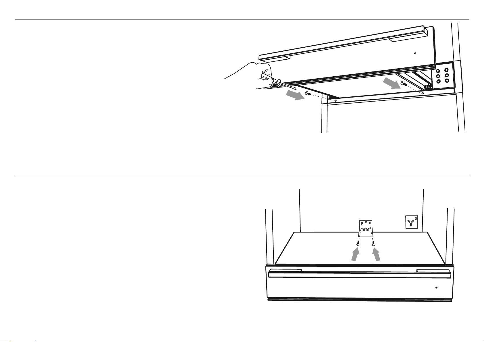
10 | TIROIR CHAUFFANT GUIDE D’INSTALLATION
1 Assurez-vous que le tiroir chauffant est de niveau et positionné dans la cavité.
IMPORTANT!
Ne soulevez pas le tiroir chauffant par la poignée du tiroir.
2 Ouvrez complètement le tiroir.
3 Fixez le tiroir chauffant en place avec les deux vis fournies, à travers la garniture
avant, sous le tiroir. Ne pas trop serrer les vis.
Si le support anti-basculement est requis (voir les exemples de scénarios),
fixez d’abord le produit à l’avant, puis placez le support centralement
à l’arrière de la cavité et placez-le sur le dessus du châssis.
Fixez-le à la paroi arrière de l’armoire à l’aide des vis fournies.
9 FIXEZ LE TIROIR CHAUFFANT AUX ARMOIRES
!0 FIXEZ LE SUPPORT ANTI-BASCULEMENT
(EN OPTION EN FONCTION DE LA CONFIGURATION DE L’ARMOIRE)

TIROIR CHAUFFANT GUIDE D’INSTALLATION | 11
!1 LISTE DE CONTRÔLE FINALE
A REMPLIR PAR L’INSTALLATEUR
F Assurez-vous que le tiroir-réchaud est de niveau et solidement fixé aux armoires.
F Assurez-vous que tout emballage interne a été retiré du tiroir.
F Assurez-vous que l’interrupteur d’isolement est accessible au client.
F Assurez-vous que le support anti-basculement a été correctement installé si nécessaire.
F Si vous installez un four directement sur le dessus du tiroir chauffant, assurez-vous que les supports de four fournis ont été installés sur le tiroir chauffant.
OPERATION DE TEST:
F Ouvrez le tiroir et appuyez sur le
bouton pour allumer le tiroir-réchaud.
Le halo marche / arrêt et le réglage de la température 2 ( ) halo doivent s’allumer en rouge.
Ferme le tiroir.
Après 5-10 minutes, ouvrez le tiroir. Les surfaces internes du tiroir doivent être légèrement réchauffées.
Appuyez sur le bouton pour éteindre le tiroir chauffant et fermer le tiroir.
Compléter et conserver pour référence sûre:
Modèle
Numéro de série
Date d’achat
Acheteur
Adresse du concessionnaire
Nom de l’installateur
Signature de l’installateur
Compagnie d’installation
Date d’installation
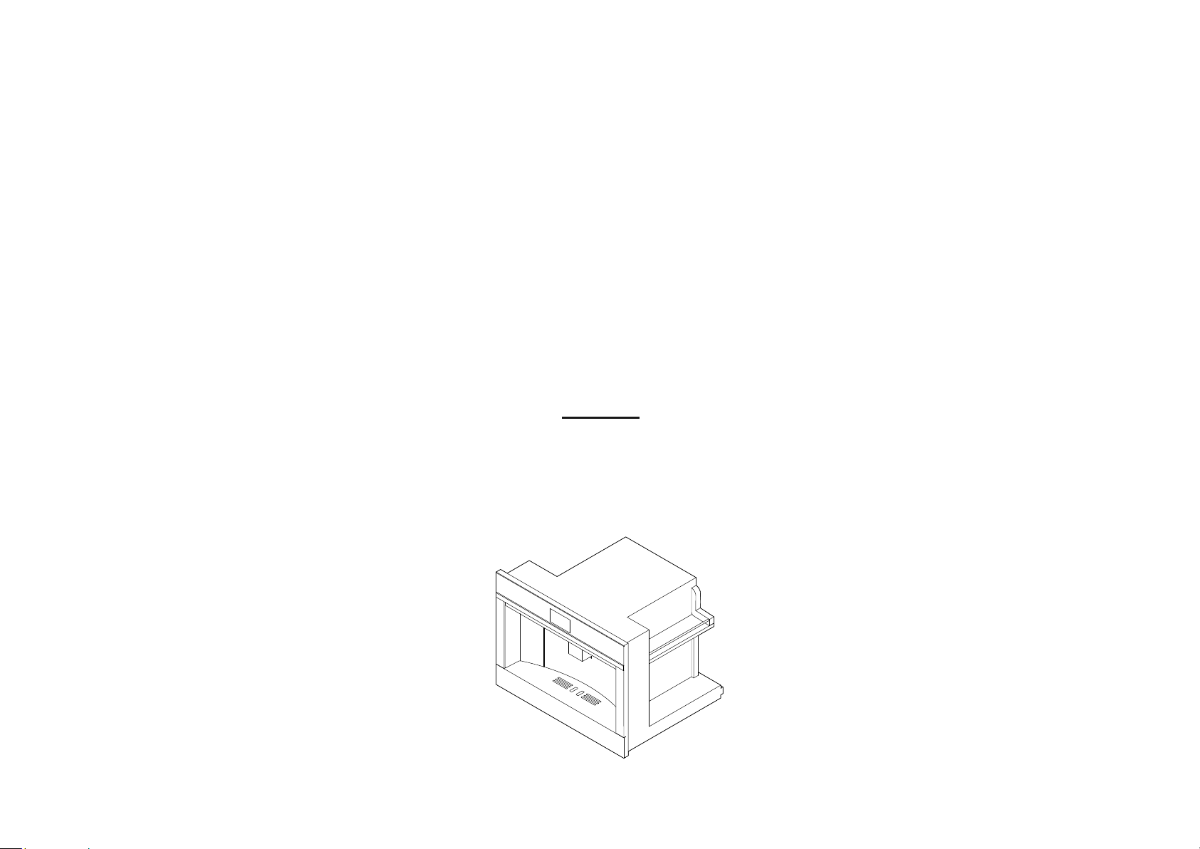
MACHINE À CAFÉ
Modèles EB24
MACHINE À CAFÉ GUIDE D’INSTALLATION | 13
IMPORTANT!
CONSERVEZ CES INSTRUCTIONS
1 SÉCURITÉ ET AVERTISSEMENTS
CONSIGNES DE SÉCURITÉ IMPORTANTES!
Installation
Vérification des dommages de transport
Après avoir retiré l’emballage, assurez-vous que le produit est complet et non endommagé et que tous
les accessoires sont présents. N’utilisez pas l’appareil s’il est visiblement endommagé. Contacter le
service client.
IMPORTANT!
●
Avant de raccorder l’appareil à l’alimentation électrique, assurez-vous que la tension et la
fréquence indiquées sur la plaque signalétique correspondent à l’alimentation électrique
domestique. En cas de doute, consultez un technicien qualifié.
●
L’appareil doit être correctement installé avant de l’utiliser pour s’assurer qu’aucun
composant électrique n’est accessible. Assurez-vous que l’appareil n’est pas alimenté
pendant les travaux d’installation, de réparation ou de maintenance.
●
Assurez-vous que votre appareil est correctement installé et mis à la terre par un technicien
qualifié. Pour garantir la sécurité électrique de cet appareil, une continuité doit exister
entre l’appareil et le système de mise à la terre efficace. Il est impératif que cette exigence
de sécurité de base soit respectée. En cas de doute, faites vérifier le système électrique
de la maison par un électricien qualifié. Le fabricant ne peut être tenu responsable des
dommages causés par le manque ou l’insuffisance d’un système de mise à la terre efficace.
●
N’utilisez pas de rallonge pour brancher l’appareil à l’électricité. La rallonge ne garantit pas
la sécurité requise de l’appareil (risque de surchauffe).
●
Avant de procéder à l’entretien ou à la maintenance, coupez l’alimentation électrique en
éteignant l’interrupteur principal et en débranchant l’appareil.
●
Installez ou installez cet appareil uniquement conformément aux instructions d’installation
fournies.
●
Les travaux d’installation et de réparation doivent être effectués uniquement par un
technicien qualifié conformément aux réglementations de sécurité nationales et locales. Les
réparations et autres travaux effectués par des personnes non autorisées pourraient être
dangereux et annuler la garantie.
●
N’utilisez que des pièces de rechange d’origine. Ce n’est qu’alors que le fabricant peut
garantir la sécurité de cette machine.
●
N’ouvrez jamais le boîtier extérieur de l’appareil. Toute altération des connexions
électriques ou des composants et pièces mécaniques est dangereuse et peut endommager
la machine.
AVERTISSEMENT!
Couper le danger
Attention – certains bords sont coupants.
Ne pas faire preuve de prudence peut entraîner des blessures ou des
coupures.
●
Si la machine est installée en combinaison avec d’autres appareils, une base de
protection doit être installée entre l’appareil et l’appareil.
●
Ne pas installer ou utiliser à l’extérieur même s’il est installé dans la vitrine.
●
Pour se protéger contre les incendies, les chocs électriques et les blessures, n’immergez
pas le cordon ou les prises dans l’eau ou d’autres liquides.
●
Pour réduire le risque de blessure, ne pas enrouler le cordon sur le comptoir ou sur la
table où les enfants pourraient tirer dessus ou trébucher involontairement.
●
Ne laissez pas le cordon pendre sur le bord d’une table ou d’un comptoir, ou touchez des
surfaces chaudes.
●
N’utilisez pas un appareil dont le cordon ou la fiche sont endommagés ou qui ne
fonctionne pas correctement ou qui a été endommagé de quelque manière que ce soit.
●
Retournez l’appareil à un centre de service autorisé pour un examen, une réparation ou
un ajustement.
●
Pour déconnecter, éteignez la machine, éteignez l’interrupteur principal puis retirez la
fiche de la prise murale.
●
Ne permettez pas aux enfants et animaux de se trouver ou circuler à proximité de
l’appareil lorsqu’il est retiré hors des armoires.
●
Ne laissez pas l’appareil retiré hors des armoires lorsqu’il est utilisé.
●
Ne laissez pas l’appareil retiré hors des armoires lorsque ce n’est pas nécessaire.
●
Installez l’appareil conformément aux instructions du manuel pour vous assurer qu’il n’y
ait aucun déversement lorsqu’il est retiré hors des armoires.
●
Le panneau de fixation des rails doit être d’une épaisseur adaptée aux vis de fixation
fournies en standard.
●
Le matériau du panneau doit être adapté au poids de l’appareil, d’environ 55 lb
(24,9 kg).
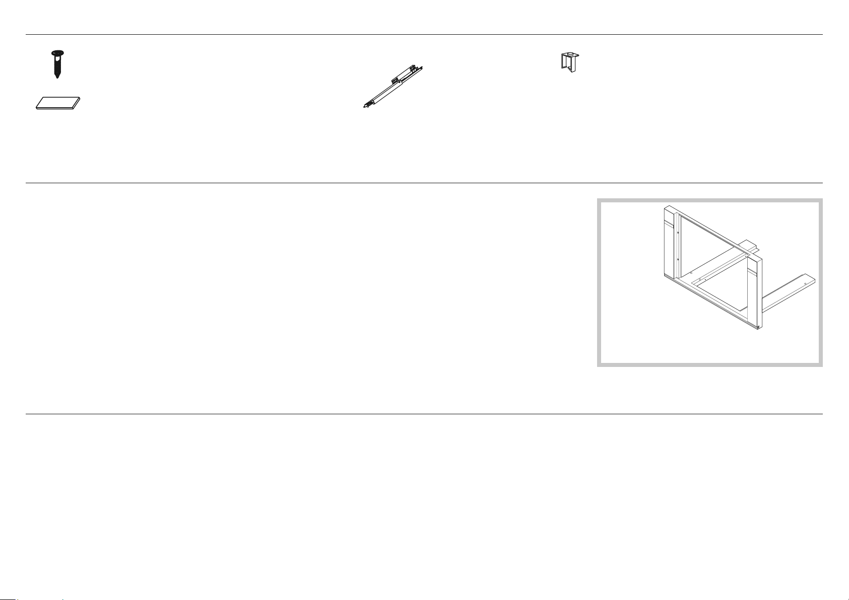
14 | MACHINE À CAFÉ GUIDE D’INSTALLATION
2 PIÈCES FOURNIES
3 AVANT L’INSTALLATION
4 APRÈS L’INSTALLATION
Des vis
(28)
Espaceurs
(4) pour le côté
(4) pour le bas
●
La cavité du comptoir et de la cafetière sont carrées et de niveau, et sont les dimensions requises.
●
L’installation sera conforme à toutes les exigences de dégagement et aux normes et règlements applicables.
●
L’interrupteur d’isolement sera facilement accessible au client avec la cafetière installée.
●
L’électricien fournit suffisamment de longueur libre du câble d’alimentation pour atteindre l’arrière de la cavité à au moins
59 1/16" (1.5 m) devant le bord inférieur de l’ouverture.
●
Le câble peut entrer dans la cavité par le côté, le haut ou le bas, mais l’entrée supérieure doit être à l’arrière de la cavité.
●
La prise de connexion de la cafetière (si installée) est à l’extérieur de la cavité si le four affleure la paroi arrière.
●
La cafetière repose sur une surface pouvant supporter son poids.
●
La hauteur du sol convient au client.
●
Vous consultez les autorités locales de construction et les règlements en cas de doute concernant l’installation.
IMPORTANT!
Certains facteurs environnementaux et habitudes de cuisson peuvent provoquer de la condensation dans et autour de
la cafetière pendant l’utilisation. Pour protéger les armoires environnantes des dommages possibles causés par une
condensation fréquente ou excessive, nous recommandons d’imperméabiliser la cavité.
IMPORTANT!
Veillez à ne pas endommager la partie inférieure de l’appareil pendant l’installation. La garniture est importante pour une circulation d’air correcte et permet à la porte de s’ouvrir
et de se fermer sans obstruction. Le fabricant décline toute responsabilité pour les dommages résultant d’une installation incorrecte.
●
La cafetière peut être utilisée complètement sans obstruction.
●
Le câble d’alimentation ne touche aucune pièce métallique chaude.
●
L’interrupteur d’isolement est facilement accessible au client avec la cafetière installée.
●
Vous remplissez la "liste de contrôle finale" à la fin de l’installation.
●
Si, après avoir suivi les instructions données, les performances correctes ne peuvent pas être atteintes, veuillez contacter le centre de service après-vente agréé Fisher & Paykel
le plus proche, ou contactez-nous via notre site Web local indiqué à la fin de ce document.
Rails (2)
Agrafe (1)
Installation du kit
de garniture en option
Si vous utilisez un kit de finition
de 30" (762mm), reportez-vous au
Guide d’installation du kit de finition séparé.
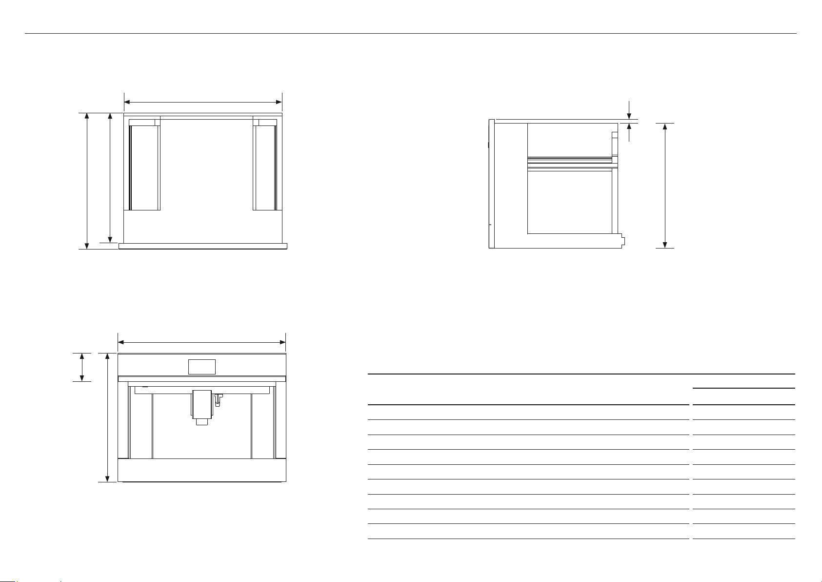
MACHINE À CAFÉ GUIDE D’INSTALLATION | 15
5 DIMENSIONS DU PRODUIT
Avant
HAUT
LE CÔTÉ
DIMENSIONS DU PRODUIT
MODÈLES EB24
Pouces (mm)
A
Hauteur totale du produit 18" (458)
B
Largeur totale du produit 23 1/2" (596)
C
Profondeur totale du produit (à l’exclusion des cadrans) 18 7/8" (480)
D
Hauteur du châssis 17 1/2" (445)
E
Largeur du châssis 22 1/16" (560)
F
Profondeur du châssis 18 1/8" (460)
G
Profondeur du cadre de la cafetière et du panneau de commande 13/16" (20)
H
Panneau de contrôle Stepdown au châssis 1/2" (13)
I
Hauteur du panneau de contrôle 4" (100)
B
E
A
C F
D
I
H
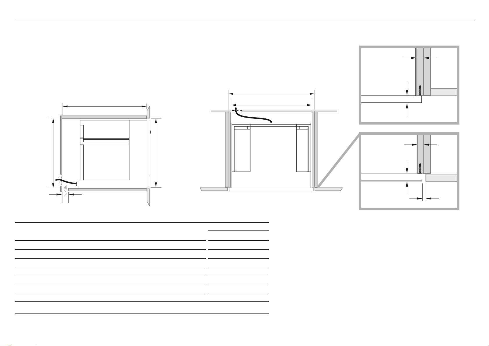
16 | MACHINE À CAFÉ GUIDE D’INSTALLATION
Vérifiez les mesures minimales requises pour une installation correcte de l’appareil. La cafetière doit être installée dans
une colonne et la colonne doit être fermement fixée au mur avec des supports disponibles dans le commerce.
IMPORTANT!
●
Toutes les opérations d’installation ou de maintenance doivent être effectuées avec l’appareil déconnecté du secteur.
●
Les meubles de cuisine en contact direct avec l’appareil doivent résister à la chaleur de 149°F min (65°C min).
●
Pour garantir une ventilation correcte, laissez un espace au fond de l’armoire (voir mesures ci-dessous).
6A DIMENSIONS DE L’ARMOIRE (CAVITÉ DE 18 1/8" (460MM) DE HAUTEUR)
FIÈRE INSTALLER
FLUSH INSTALLER
5/8–13/16"
(16–20mm)
min 1/16" (2mm)
5/8–13/16"
(16–20mm)
Fourniture électrique
CABINETRY DIMENSIONS
MODÈLES EB24
Pouces (mm)
I
Largeur intérieure minimale de la cavité 22 1/16" (560)
J
Largeur totale des armoires 23 5/8" (600)
K
Hauteur intérieure minimale de la cavité 17 3/4" (450)
L
Hauteur totale des armoires 18 1/8" (460)
M
Profondeur intérieure minimale de la cavité 21 7/16" (545)
n
Ventilation d’aération 2" (50)
Remarque: Si vous installez une table de cuisson au-dessus de la cafetière, assurez-vous que la surface de cuisson est suffisamment
dégagée selon les instructions du fabricant de la table de cuisson.
HAUTLE CÔTÉ
M
J
I
Lk
n
13/16"
(20mm)
13/16"
(20mm)
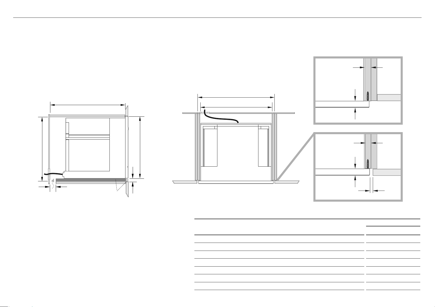
MACHINE À CAFÉ GUIDE D’INSTALLATION | 17
Vérifiez les mesures minimales requises pour une installation correcte de l’appareil. La cafetière doit être installée dans une
colonne et la colonne doit être fermement fixée au mur avec des supports disponibles dans le commerce.
Trousse de garniture inférieure
Le kit Lower Trim montré est disponible à commander séparément auprès de fisherpaykel.com.
Pour installer le kit de finition, reportez-vous aux instructions qui l’accompagnent.
IMPORTANT!
●
Toutes les opérations d’installation ou de maintenance doivent être effectuées avec l’appareil déconnecté du secteur.
●
Les meubles de cuisine en contact direct avec l’appareil doivent résister à la chaleur de 149°F min (65°C min).
●
Pour garantir une ventilation correcte, laissez un espace au fond de l’armoire (voir mesures ci-dessous).
6B DIMENSIONS DE L’ARMOIRE (KIT DE GARNITURE DE CAVITÉ DE 18 7/8" (480MM))
HAUTLE CÔTÉ
Fourniture électrique
o
Trousse de
garniture
inférieure
M
J
I
Lk
n
CABINETRY DIMENSIONS
MODÈLES EB24
Pouces (mm)
I
Largeur intérieure minimale de la cavité 22 1/16" (560)
J
Largeur totale des armoires 23 5/8" (600)
K
Hauteur intérieure minimale de la cavité 18 1/2" (470)
L
Hauteur totale des armoires 18 7/8" (480)
M
Profondeur intérieure minimale de la cavité 21 7/16" (545)
n
Ventilation d’aération 2" (50)
o
Hauteur du kit de finition
13/16" (20)
FIÈRE INSTALLER
FLUSH INSTALLER
5/8–13/16"
(16–20mm)
min 1/16" (2mm)
5/8–13/16"
(16–20mm)
13/16"
(20mm)
13/16"
(20mm)
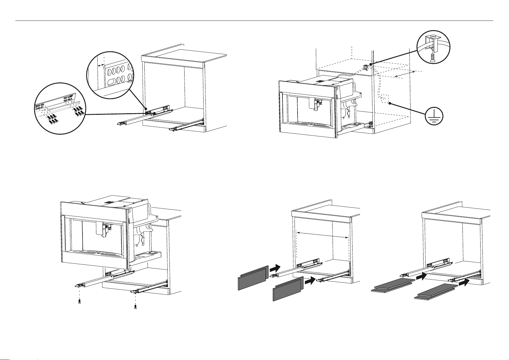
18 | MACHINE À CAFÉ GUIDE D’INSTALLATION
1 Positionnez les rails sur les côtés de l’armoire. Fixer avec les vis fournies, puis les extraire
complètement.
●
Si la cafetière est installée sur un tiroir chauffant, utilisez la surface supérieure comme
référence pour positionner les rails.
●
Dans ce cas, il n’y aura pas de surface sur laquelle reposer les rails.
2 Fixez le câble d’alimentation avec le clip. Le câble d’alimentation doit être suffisamment
long pour permettre à l’appareil d’être extrait de l’armoire pour remplir le conteneur de
grains de café.
●
L’appareil doit être mis à la terre conformément à la législation.
●
Les connexions électriques doivent être effectuées par un électricien qualifié en suivant
les instructions.
3 Positionnez l’appareil sur les rails, en vous assurant que les broches sont
correctement insérées dans les boîtiers, puis fixez-les avec les vis fournies.
Si la hauteur de l’appareil nécessite un réglage, utilisez les disques
d’espacement fournis.
4 Si nécessaire, corriger l’alignement de l’appareil en positionnant les entretoises
fournies sous ou sur les côtés du support.
7 INSTRUCTIONS D’INSTALLATION
environ 13 3/4" (350mm)
22 1/16" min.
(560mm min.)
0.07"
(1.8mm)

MACHINE À CAFÉ GUIDE D’INSTALLATION | 19
A REMPLIR PAR L’INSTALLATEUR
F Assurez-vous que la cafetière est de niveau et solidement fixée aux armoires.
F Vérifiez que la garniture inférieure n’est pas endommagée.
F Vérifiez qu’il y a un dégagement suffisant. Ceci afin d’assurer une circulation d’air correcte.
F Assurez-vous que les attaches de câble et l’emballage interne ont été retirés de la cavité de la cafetière.
F Assurez-vous que toutes les ouvertures et toutes les ouvertures de la cafetière sont dégagées et qu’elles ne sont pas obstruées ou endommagées.
IMPORTANT!
Si vous ne vous assurez pas que toutes les ouvertures d’aération sont dégagées, les performances du produit peuvent être médiocres.
F Assurez-vous que l’interrupteur d’isolement est accessible au client.
OPÉRATION DE TEST:
F Mettez l’appareil sous tension. L’affichage devrait s’allumer.
F Avez-vous démontré l’opération de base au client?
F Remplissez le réservoir d’eau jusqu’au niveau indiqué.
8 LISTE DE CONTRÔLE FINALE
Compléter et conserver pour référence sûre:
Modèle
Numéro de série
Date d’achat
Acheteur
Adresse du concessionnaire
Nom de l’installateur
Signature de l’installateur
Compagnie d’installation
Date d’installation

FOUR À VAPEUR
Modèles OS24N

FOUR À VAPEUR GUIDE D’INSTALLATION | 21
IMPORTANT!
CONSERVEZ CES INSTRUCTIONS
1 SÉCURITÉ ET AVERTISSEMENTS
Installation
AVERTISSEMENT!
Risque d’incendie
N’utilisez pas d’adaptateurs, de réducteurs ou de dispositifs de
dérivation pour raccorder cet appareil à l’alimentation secteur.
Le non-respect de ce conseil peut entraîner une surchauffe, une brûlure
ou un incendie.
AVERTISSEMENT!
Couper le danger
Attention – certains bords sont coupants.
Ne pas faire preuve de prudence peut entraîner des blessures ou des
coupures.
AVERTISSEMENT!
Danger de choc électrique
Avant d’effectuer tout travail sur la partie électrique de l’appareil,
celui-ci doit être déconnecté du secteur.
La connexion à un bon système de mise à la terre est absolument
essentielle et obligatoire.
Les modifications apportées au système de câblage domestique ne
doivent être effectuées que par un électricien qualifié.
Le non-respect de ce conseil peut entraîner un choc électrique ou la mort.
●
Si l’installation nécessite des modifications du système électrique domestique, appelez un
électricien qualifié. L’électricien doit également vérifier que la section du câble de prise est
adaptée à l’électricité tirée par le four.
●
Le four doit être mis à la terre.
●
L’installation doit être conforme aux réglementations locales en matière de construction
et d’électricité.
●
Cet appareil doit être installé et branché sur le secteur uniquement par une personne
qualifiée conformément à ces instructions d’installation et conformément aux
réglementations locales applicables en matière de construction et d’électricité. Si vous
n’installez pas l’appareil correctement, cela pourrait invalider toute réclamation de garantie
ou de responsabilité.
●
Si le câble d’alimentation est endommagé, il doit être remplacé par le fabricant, son agent
de service ou une personne de qualification similaire afin d’éviter tout danger.
●
Un disjoncteur est recommandé.
●
N’utilisez pas d’adaptateurs, de réducteurs ou de dispositifs de dérivation pour raccorder
le four à l’alimentation secteur car ils peuvent provoquer une surchauffe et une brûlure.
●
Assurez-vous que la cavité est complètement scellée sans espaces. Ceci permet de s’assurer
que le système de refroidissement du four fonctionne correctement.
●
Ne permettez pas aux enfants et animaux de se trouver ou circuler à proximité de l’appareil
lorsqu’il est retiré hors des armoires.
Exigences électriques
●
Connectez le four avec du fil de cuivre seulement.
●
Ne pas couper le conduit.
●
Un U.L. Le connecteur de conduit listé doit être fourni à la boîte de jonction.
●
Ne pas broyer sur un tuyau de gaz.
●
Ne pas avoir de fusible dans le circuit de mise à la terre ou dans le neutre.
●
Fuse les deux côtés de la ligne.
●
Un fusible temporisé ou un disjoncteur est recommandé. Si vous utilisez un fusible temporisé,
fusionnez les deux côtés de la ligne.
●
Le câble blindé flexible de l’appareil doit être connecté directement à la boîte de jonction.
●
Connectez-le directement au disjoncteur à fusible (ou au boîtier du disjoncteur) par l’intermédiaire
d’un câble en cuivre souple gainé, blindé ou non métallique (avec fil de mise à la terre).
●
Si les codes le permettent et qu’un fil de mise à la terre distinct est utilisé, il est recommandé
qu’un électricien qualifié détermine que le chemin de mise à la terre et la jauge de fil sont
conformes aux codes locaux.
CONSIGNES DE SÉCURITÉ IMPORTANTES!
Pour éviter tout danger, suivez ces instructions attentivement avant d’installer ou d’utiliser
cet appareil.
●
Conservez ces instructions pour l’utilisation par les inspecteurs locaux.
●
Veuillez mettre cette information à la disposition de la personne qui installe l’appareil,
ce qui pourrait réduire vos coûts d’installation.
●
Ce four doit être installé et connecté à l’alimentation électrique uniquement Personne autorisée.

22 | FOUR À VAPEUR GUIDE D’INSTALLATION
2 AVANT L’INSTALLATION
3 APRÈS L’INSTALLATION
●
Le comptoir et la cavité du four sont carrés et de niveau, et sont les dimensions requises.
●
L’installation sera conforme à toutes les exigences de dégagement et aux normes et règlements applicables.
●
L’interrupteur d’isolement sera facilement accessible au client avec le four installé.
●
L’électricien fournit suffisamment de longueur libre du câble d’alimentation pour atteindre l’arrière de la cavité à au moins
59 1/16" (1.5 m) devant le bord inférieur de l’ouverture.
●
Le câble peut entrer dans la cavité par le côté, le haut ou le bas, mais l’entrée supérieure doit être à l’arrière de la cavité.
●
La prise de raccordement au four (si installée) est à l’extérieur de la cavité si le four affleure la paroi arrière.
●
Le four reposera sur une surface pouvant supporter son poids.
●
La hauteur du sol convient au client.
●
Vous consultez les autorités locales de construction et les règlements en cas de doute concernant l’installation.
IMPORTANT!
Certains facteurs environnementaux et habitudes de cuisson peuvent provoquer de la condensation dans et autour
du four pendant l’utilisation. Pour protéger les armoires environnantes des dommages possibles causés par une
condensation fréquente ou excessive, nous recommandons d’imperméabiliser la cavité du four.
IMPORTANT!
Veillez à ne pas endommager la partie inférieure du four lors de l’installation. La garniture est importante pour une circulation d’air correcte et permet à la porte de s’ouvrir et
de se fermer sans obstruction. Le fabricant décline toute responsabilité pour les dommages résultant d’une installation incorrecte.
●
La (les) porte (s) du four peuvent s’ouvrir complètement sans obstruction.
●
Le câble d’alimentation ne touche aucune pièce métallique chaude.
●
L’interrupteur d’isolement est facilement accessible au client lorsque le four est installé.
●
Vous remplissez la "liste de contrôle finale" à la fin de l’installation.
●
Si, après avoir suivi les instructions données, les performances correctes ne peuvent pas être atteintes, veuillez contacter le centre de service après-vente agréé Fisher & Paykel
le plus proche, ou contactez-nous via notre site Web local indiqué à la fin de ce document.
Installation du kit
de garniture en option
Si vous utilisez un kit de finition
de 30" (762mm), reportez-vous au
Guide d’installation du kit de finition séparé.
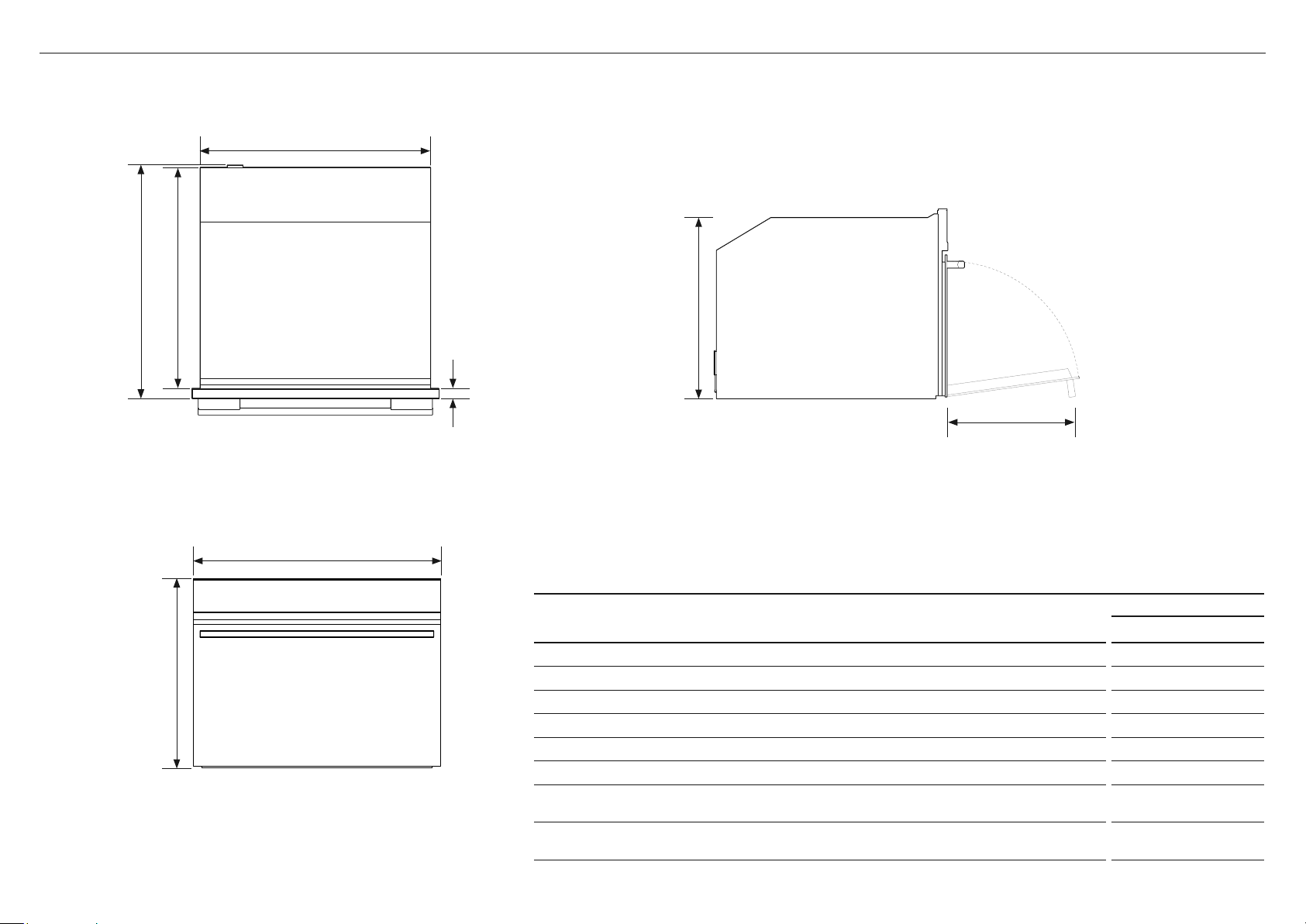
FOUR À VAPEUR GUIDE D’INSTALLATION | 23
4 DIMENSIONS DU PRODUIT
Avant
HAUT LE CÔTÉ
DIMENSIONS DU PRODUIT
MODÈLES OS24N
Pouces (mm)
A
Hauteur totale du produit 18" (458)
B
Largeur totale du produit 23 7/16" (596)
C
Profondeur totale du produit (à l’exclusion de la poignée et des cadrans) 22 1/8" (562)
D
Hauteur du châssis 17 1/2" (445)
E
Largeur du châssis 21 7/8" (556)
F
Profondeur du châssis 21 1/4" (540)
G
Profondeur du cadre du four et du panneau de commande
(=distance entre l’avant du châssis et l’avant de la porte du four, à l’exclusion des boutons)
7/8" (22)
H
Profondeur de la porte du four lorsqu’elle est complètement ouverte
(mesurée depuis l’avant du panneau de commande)
12 5/8" (320)
B
A
D
H
E
C F
G
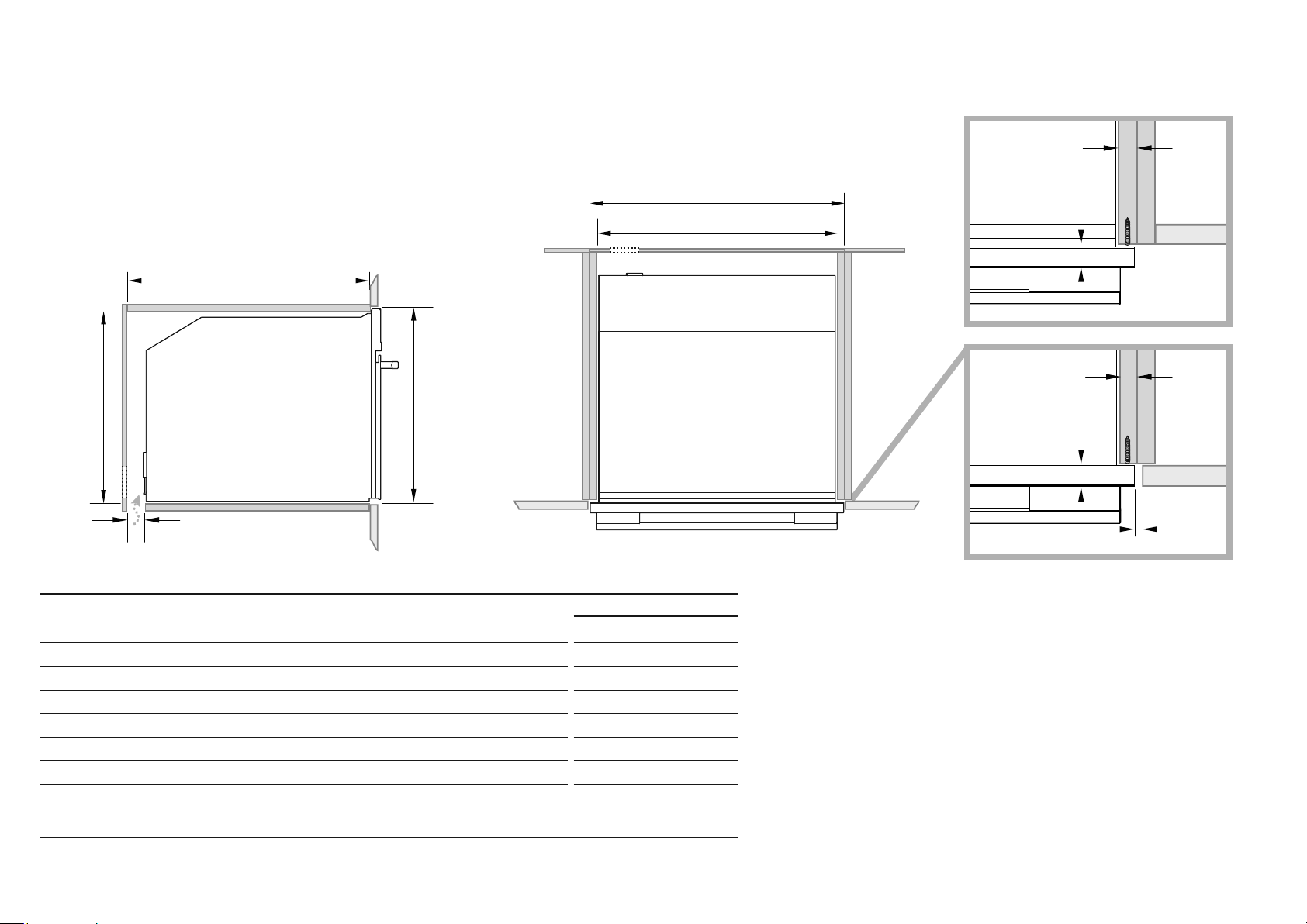
24 | FOUR À VAPEUR GUIDE D’INSTALLATION
HAUTLE CÔTÉ
CABINETRY DIMENSIONS
MODÈLES OS24N
Pouces (mm)
I
Largeur intérieure minimale de la cavité 22 1/16" (560)
J
Largeur totale des armoires 23 5/8" (600)
K
Hauteur intérieure minimale de la cavité 17 3/4" (450)
L
Hauteur totale des armoires 18 1/8" (460)
M
Profondeur intérieure minimale de la cavité 22 1/16" (560)
n
Ventilation d’aération
2" (50)
Remarque: Si vous installez une table de cuisson au-dessus du four, assurez-vous que la surface de cuisson est suffisamment dégagée
selon les instructions du fabricant de la table de cuisson.
5A DIMENSIONS DE L’ARMOIRE (CAVITÉ DE 18 1/8" (460MM) DE HAUTEUR)
●
Le four doit être installé sous une table de cuisson, dans une colonne ou combiné avec le tiroir-réchaud.
●
Le matériau de l’armoire doit être capable de résister à la chaleur.
●
Le four doit être centré dans les parois de l’armoire et fixé avec les vis et les bagues fournies.
Fourniture électrique
M
J
I
Lk
n
FIÈRE INSTALLER
FLUSH INSTALLER
5/8–13/16"
(16–20mm)
min 1/16" (2mm)
5/8–13/16"
(16–20mm)
7/ 8"
(22mm)
7/ 8"
(22mm)

FOUR À VAPEUR GUIDE D’INSTALLATION | 25
HAUTLE CÔTÉ
CABINETRY DIMENSIONS
MODÈLES OS24N
Pouces (mm)
I
Largeur intérieure minimale de la cavité 22 1/16" (560)
J
Largeur totale des armoires 23 5/8" (600)
K
Hauteur intérieure minimale de la cavité 18 1/2" (470)
L
Hauteur totale des armoires 18 7/8" (480)
M
Profondeur intérieure minimale de la cavité 22 1/16" (560)
n
Ventilation d’aération 2" (50)
o
Hauteur du kit de finition
13/16" (20)
Remarque: Si vous installez une table de cuisson au-dessus du four, assurez-vous que la surface de cuisson est suffisamment dégagée
selon les instructions du fabricant de la table de cuisson.
5B DIMENSIONS DE L’ARMOIRE (KIT DE GARNITURE DE CAVITÉ DE 18 7/8" (480MM))
●
Le four doit être installé sous une table de cuisson, dans une colonne ou combiné avec le tiroir-réchaud.
●
Le matériau de l’armoire doit être capable de résister à la chaleur.
●
Le four doit être centré dans les parois de l’armoire et fixé avec les vis et les bagues fournies.
Trousse de garniture inférieure
Le kit Lower Trim montré est disponible à commander séparément auprès de fisherpaykel.com.
Pour installer le kit de finition, reportez-vous aux instructions qui l’accompagnent.
Fourniture électrique
o
Trousse de
garniture
inférieure
M
J
I
Lk
n
FIÈRE INSTALLER
FLUSH INSTALLER
5/8–13/16"
(16–20mm)
min 1/16" (2mm)
5/8–13/16"
(16–20mm)
7/ 8"
(22mm)
7/ 8"
(22mm)

26 | FOUR À VAPEUR GUIDE D’INSTALLATION
7 FIXEZ LE FOUR AUX ARMOIRES
1 Placez le four dans la cavité préparée.
IMPORTANT!
Ne soulevez pas le four par la poignée de la porte.
2 Utilisez les vis et les entretoises fournies pour fixer le four aux armoires.
IMPORTANT!
●
Ne serrez pas trop les vis.
●
Veillez à ne pas endommager la partie inférieure du four.
●
Ne pas sceller le four dans les armoires avec du silicone ou de la colle.
Cela rend l’entretien ultérieur difficile. Fisher & Paykel ne couvrira pas
les coûts d’enlèvement du four, ou des dommages causés par ce retrait.
S’assurer que l’entretoise
fournie est installée entre
le four et les armoires
Avant de vous connecter à l’électricité, assurez-vous que:
●
les spécifications du système électrique correspondent à ce qui est détaillé sur cette section. (Fig. 1)
●
le système a une connexion au sol efficace conforme aux normes et lois en vigueur.
La connexion au sol est requise par la loi. Le câble ne doit à aucun moment atteindre une température supérieure à 122 ° F (50 °
C) au-dessus de la température ambiante.
Ce four doit être connecté à l’électricité par un câble d’alimentation et une fiche compatible avec la sortie du système électrique
qui alimente ce four. Si un appareil fixe n’a pas de cordon d’alimentation et de prise, ou un autre appareil qui assure une
déconnexion
du secteur, avec une distance d’ouverture des contacts qui permet une déconnexion complète, de tels dispositifs de déconnexion
doivent être prévus dans le réseau d’alimentation conforme à l’installation règles.
La prise ou l’interrupteur omnipolaire doit être facile à atteindre lorsque l’appareil est installé.
Remarque: Le fabricant décline toute responsabilité si les normes habituelles de prévention des accidents et les instructions
ci-dessus ne sont pas respectées.
6 BRANCHEMENT ÉLECTRIQUE
MAXIMUM D’ÉNERGIE (W) HZ VOLTAGE (V) AMPS (A)
3000 60 Hz 240V 12.5
2250 60 Hz 1208V 10.8
connecteur de
conduit
homologué UL
boîte de
câblage
mural
câble
d’alimentation
électrique
fils rouges
fils blancs
fils verts de mise
àla terre du four -
regroupés en usine
fils noirs
Fig. 1

FOUR À VAPEUR GUIDE D’INSTALLATION | 27
8 LISTE DE CONTRÔLE FINALE
A REMPLIR PAR L’INSTALLATEUR
F Assurez-vous que le four est de niveau et solidement fixé aux armoires.
F Vérifiez que la garniture inférieure n’est pas endommagée.
F Ouvrez lentement la porte du four jusqu’à ce qu’elle soit complètement ouverte et vérifiez qu’il y a un espace suffisant entre le bas de la porte et la garniture inférieure.
Ceci afin d’assurer une circulation d’air correcte. Si les moulures inférieures sont endommagées, redressez la moulure et assurez-vous que la porte du four s’ouvre
complètement sans obstruction.
F Assurez-vous que les attaches de câbles et l’emballage interne ont été retirés de la cavité du four.
F Assurez-vous que tous les évents et les ouvertures du four sont dégagés et qu’ils ne sont pas obstrués ou endommagés.
IMPORTANT!
Si vous ne vous assurez pas que toutes les fentes d’aération du four sont dégagées, la performance du produit peut être médiocre.
F Assurez-vous que l’interrupteur d’isolement est accessible au client.
OPERATION DE TEST:
F Avez-vous démontré l’opération de base au client?
Reportez-vous au Guide de l’utilisateur.
Compléter et conserver pour référence sûre:
Modèle
Numéro de série
Date d’achat
Acheteur
Adresse du concessionnaire
Nom de l’installateur
Signature de l’installateur
Compagnie d’installation
Date d’installation
FISHERPAYKEL.COM
© Fisher&Paykel Appliances 2020. Tous droits réservés.
Les caractéristiques de produit présentées dans ce document
s’appliquent aux modèles et produits spécifiques qui y sont décrits à la
date de publication. Dans le cadre de notre politique d’amélioration en
permanence de nos produits, ces caractéristiques peuvent être modifiées
à tout moment. Nous vous recommandons de vérifier auprès de votre
détaillant que ce document décrit le produit actuellement disponible.
Pour les plus récentes informations sur la disponibilité des modèles et des
caractéristiques dans votre pays, visitez notre site Web fisherpaykel.com
ou contactez votre détaillant Fisher&Paykel local.

FOUR À MICRO-ONDES
Modèles OM24N

FOUR À MICRO-ONDE GUIDE D’INSTALLATION | 29
IMPORTANT!
CONSERVEZ CES INSTRUCTIONS
1 SÉCURITÉ ET AVERTISSEMENTS
Installation
AVERTISSEMENT!
Risque d’incendie
N’utilisez pas d’adaptateurs, de réducteurs ou de dispositifs de
dérivation pour raccorder cet appareil à l’alimentation secteur.
Le non-respect de ce conseil peut entraîner une surchauffe, une brûlure
ou un incendie.
AVERTISSEMENT!
Couper le danger
Attention – certains bords sont coupants.
Ne pas faire preuve de prudence peut entraîner des blessures ou des
coupures.
AVERTISSEMENT!
Danger de choc électrique
Avant d’effectuer tout travail sur la partie électrique de l’appareil,
celui-ci doit être déconnecté du secteur.
La connexion à un bon système de mise à la terre est absolument
essentielle et obligatoire.
Les modifications apportées au système de câblage domestique ne
doivent être effectuées que par un électricien qualifié.
Le non-respect de ce conseil peut entraîner un choc électrique ou la mort.
●
Si l’installation nécessite des modifications du système électrique domestique, appelez un
électricien qualifié. L’électricien doit également vérifier que la section du câble de prise est
adaptée à l’électricité tirée par le four.
●
Le four doit être mis à la terre.
●
L’installation doit être conforme aux réglementations locales en matière de construction
et d’électricité.
●
Cet appareil doit être installé et branché sur le secteur uniquement par une personne
qualifiée conformément à ces instructions d’installation et conformément aux
réglementations locales applicables en matière de construction et d’électricité. Si vous
n’installez pas l’appareil correctement, cela pourrait invalider toute réclamation de garantie
ou de responsabilité.
●
Si le câble d’alimentation est endommagé, il doit être remplacé par le fabricant, son agent
de service ou une personne de qualification similaire afin d’éviter tout danger.
●
Un disjoncteur est recommandé.
●
N’utilisez pas d’adaptateurs, de réducteurs ou de dispositifs de dérivation pour raccorder
le four à l’alimentation secteur car ils peuvent provoquer une surchauffe et une brûlure.
●
Assurez-vous que la cavité est complètement scellée sans espaces. Ceci permet de s’assurer
que le système de refroidissement du four fonctionne correctement.
●
Ne permettez pas aux enfants et animaux de se trouver ou circuler à proximité de l’appareil
lorsqu’il est retiré hors des armoires.
Exigences électriques
●
Connectez le four avec du fil de cuivre seulement.
●
Ne pas couper le conduit.
●
Un U.L. Le connecteur de conduit listé doit être fourni à la boîte de jonction.
●
Ne pas broyer sur un tuyau de gaz.
●
Ne pas avoir de fusible dans le circuit de mise à la terre ou dans le neutre.
●
Fuse les deux côtés de la ligne.
●
Un fusible temporisé ou un disjoncteur est recommandé. Si vous utilisez un fusible temporisé,
fusionnez les deux côtés de la ligne.
●
Le câble blindé flexible de l’appareil doit être connecté directement à la boîte de jonction.
●
Connectez-le directement au disjoncteur à fusible (ou au boîtier du disjoncteur) par l’intermédiaire
d’un câble en cuivre souple gainé, blindé ou non métallique (avec fil de mise à la terre).
●
Si les codes le permettent et qu’un fil de mise à la terre distinct est utilisé, il est recommandé
qu’un électricien qualifié détermine que le chemin de mise à la terre et la jauge de fil sont
conformes aux codes locaux.
CONSIGNES DE SÉCURITÉ IMPORTANTES!
Pour éviter tout danger, suivez ces instructions attentivement avant d’installer ou d’utiliser
cet appareil.
●
Conservez ces instructions pour l’utilisation par les inspecteurs locaux.
●
Veuillez mettre cette information à la disposition de la personne qui installe l’appareil,
ce qui pourrait réduire vos coûts d’installation.
●
Ce four doit être installé et connecté à l’alimentation électrique uniquement Personne autorisée.

30 | FOUR À MICRO-ONDE GUIDE D’INSTALLATION
2 AVANT L’INSTALLATION
3 APRÈS L’INSTALLATION
●
Le comptoir et la cavité du four sont carrés et de niveau, et sont les dimensions requises.
●
L’installation sera conforme à toutes les exigences de dégagement et aux normes et règlements applicables.
●
L’interrupteur d’isolement sera facilement accessible au client avec le four installé.
●
L’électricien fournit suffisamment de longueur libre du câble d’alimentation pour atteindre l’arrière de la cavité à au moins
59 1/16" (1.5 m) devant le bord inférieur de l’ouverture.
●
Le câble peut entrer dans la cavité par le côté, le haut ou le bas, mais l’entrée supérieure doit être à l’arrière de la cavité.
●
La prise de raccordement au four (si installée) est à l’extérieur de la cavité si le four affleure la paroi arrière.
●
Le four reposera sur une surface pouvant supporter son poids.
●
La hauteur du sol convient au client.
●
Vous consultez les autorités locales de construction et les règlements en cas de doute concernant l’installation.
IMPORTANT!
Certains facteurs environnementaux et habitudes de cuisson peuvent provoquer de la condensation dans et autour
du four pendant l’utilisation. Pour protéger les armoires environnantes des dommages possibles causés par une
condensation fréquente ou excessive, nous recommandons d’imperméabiliser la cavité du four.
IMPORTANT!
Veillez à ne pas endommager la partie inférieure du four lors de l’installation. La garniture est importante pour une circulation d’air correcte et permet à la porte de s’ouvrir et
de se fermer sans obstruction. Le fabricant décline toute responsabilité pour les dommages résultant d’une installation incorrecte.
●
La (les) porte (s) du four peuvent s’ouvrir complètement sans obstruction.
●
Le câble d’alimentation ne touche aucune pièce métallique chaude.
●
L’interrupteur d’isolement est facilement accessible au client lorsque le four est installé.
●
Vous remplissez la "liste de contrôle finale" à la fin de l’installation.
●
Si, après avoir suivi les instructions données, les performances correctes ne peuvent pas être atteintes, veuillez contacter le centre de service après-vente agréé Fisher & Paykel
le plus proche, ou contactez-nous via notre site Web local indiqué à la fin de ce document.
Installation du kit
de garniture en option
Si vous utilisez un kit de finition
de 30" (762mm), reportez-vous au
Guide d’installation du kit de finition séparé.

FOUR À MICRO-ONDE GUIDE D’INSTALLATION | 31
4 DIMENSIONS DU PRODUIT
Avant
HAUT LE CÔTÉ
DIMENSIONS DU PRODUIT
MODÈLES OM24N
Pouces (mm)
A
Hauteur totale du produit 18" (458)
B
Largeur totale du produit 23 7/16" (596)
C
Profondeur totale du produit (à l’exclusion de la poignée et des cadrans) 22 1/8" (562)
D
Hauteur du châssis 17 1/2" (445)
E
Largeur du châssis 21 7/8" (556)
F
Profondeur du châssis 21 1/4" (540)
G
Profondeur du cadre du four et du panneau de commande
(=distance entre l’avant du châssis et l’avant de la porte du four, à l’exclusion des boutons)
7/8" (22)
H
Profondeur de la porte du four lorsqu’elle est complètement ouverte
(mesurée depuis l’avant du panneau de commande)
12 5/8" (320)
B
A
D
H
E
C F
G

32 | FOUR À MICRO-ONDE GUIDE D’INSTALLATION
HAUTLE CÔTÉ
CABINETRY DIMENSIONS
MODÈLES OM24N
Pouces (mm)
I
Largeur intérieure minimale de la cavité 22 1/16" (560)
J
Largeur totale des armoires 23 5/8" (600)
K
Hauteur intérieure minimale de la cavité 17 3/4" (450)
L
Hauteur totale des armoires 18 1/8" (460)
M
Profondeur intérieure minimale de la cavité 22 1/16" (560)
n
Ventilation d’aération
2" (50)
Remarque: Si vous installez une table de cuisson au-dessus du four, assurez-vous que la surface de cuisson est suffisamment dégagée
selon les instructions du fabricant de la table de cuisson.
5A DIMENSIONS DE L’ARMOIRE (CAVITÉ DE 18 1/8" (460MM) DE HAUTEUR)
●
Le four doit être installé sous une table de cuisson, dans une colonne ou combiné avec le tiroir-réchaud.
●
Le matériau de l’armoire doit être capable de résister à la chaleur.
●
Le four doit être centré dans les parois de l’armoire et fixé avec les vis et les bagues fournies.
Fourniture électrique
M
J
I
Lk
n
FIÈRE INSTALLER
FLUSH INSTALLER
5/8–13/16"
(16–20mm)
min 1/16" (2mm)
5/8–13/16"
(16–20mm)
7/ 8"
(22mm)
7/ 8"
(22mm)
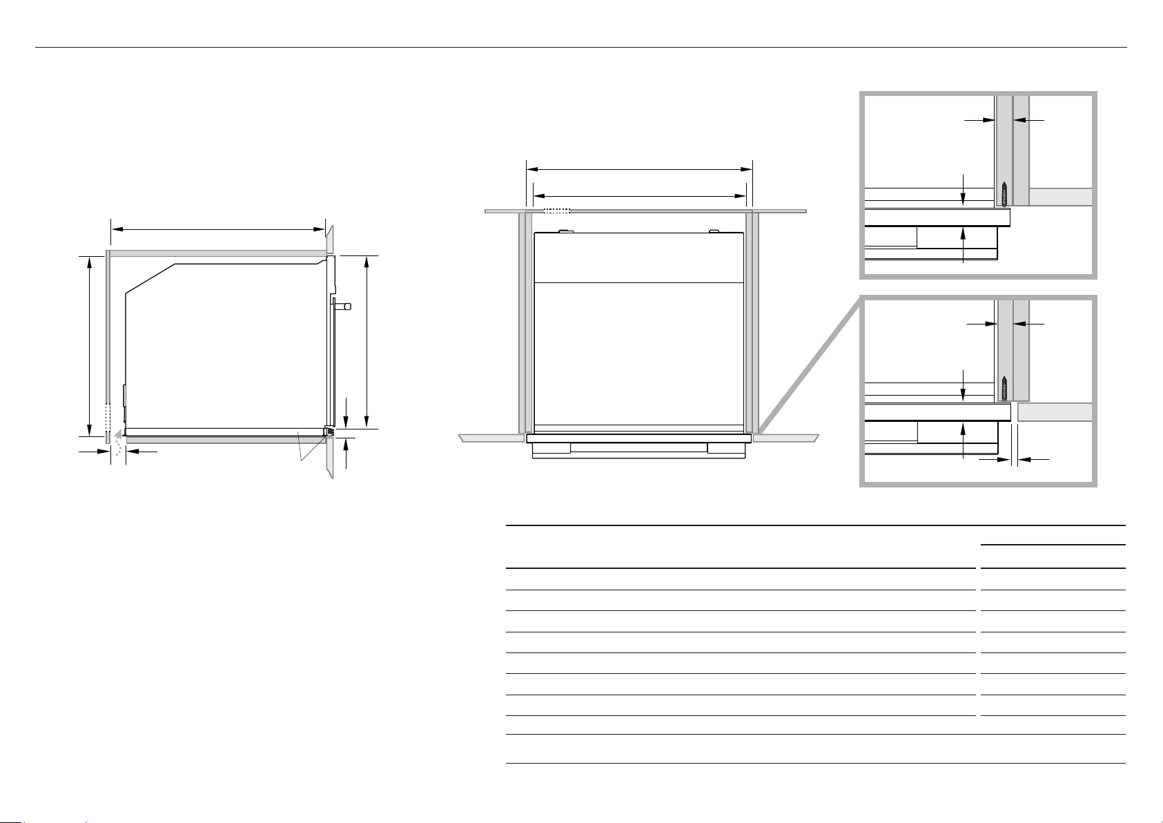
FOUR À MICRO-ONDE GUIDE D’INSTALLATION | 33
HAUTLE CÔTÉ
CABINETRY DIMENSIONS
MODÈLES OM24N
Pouces (mm)
I
Largeur intérieure minimale de la cavité 22 1/16" (560)
J
Largeur totale des armoires 23 5/8" (600)
K
Hauteur intérieure minimale de la cavité 18 1/2" (470)
L
Hauteur totale des armoires 18 7/8" (480)
M
Profondeur intérieure minimale de la cavité 22 1/16" (560)
n
Ventilation d’aération 2" (50)
o
Hauteur du kit de finition
13/16" (20)
Remarque: Si vous installez une table de cuisson au-dessus du four, assurez-vous que la surface de cuisson est suffisamment dégagée
selon les instructions du fabricant de la table de cuisson.
5B DIMENSIONS DE L’ARMOIRE (KIT DE GARNITURE DE CAVITÉ DE 18 7/8" (480MM))
●
Le four doit être installé sous une table de cuisson, dans une colonne ou combiné avec le tiroir-réchaud.
●
Le matériau de l’armoire doit être capable de résister à la chaleur.
●
Le four doit être centré dans les parois de l’armoire et fixé avec les vis et les bagues fournies.
Trousse de garniture inférieure
Le kit Lower Trim montré est disponible à commander séparément auprès de fisherpaykel.com.
Pour installer le kit de finition, reportez-vous aux instructions qui l’accompagnent.
Fourniture électrique
o
Trousse de
garniture
inférieure
M
J
I
Lk
n
FIÈRE INSTALLER
FLUSH INSTALLER
5/8–13/16"
(16–20mm)
min 1/16" (2mm)
5/8–13/16"
(16–20mm)
7/ 8"
(22mm)
7/ 8"
(22mm)
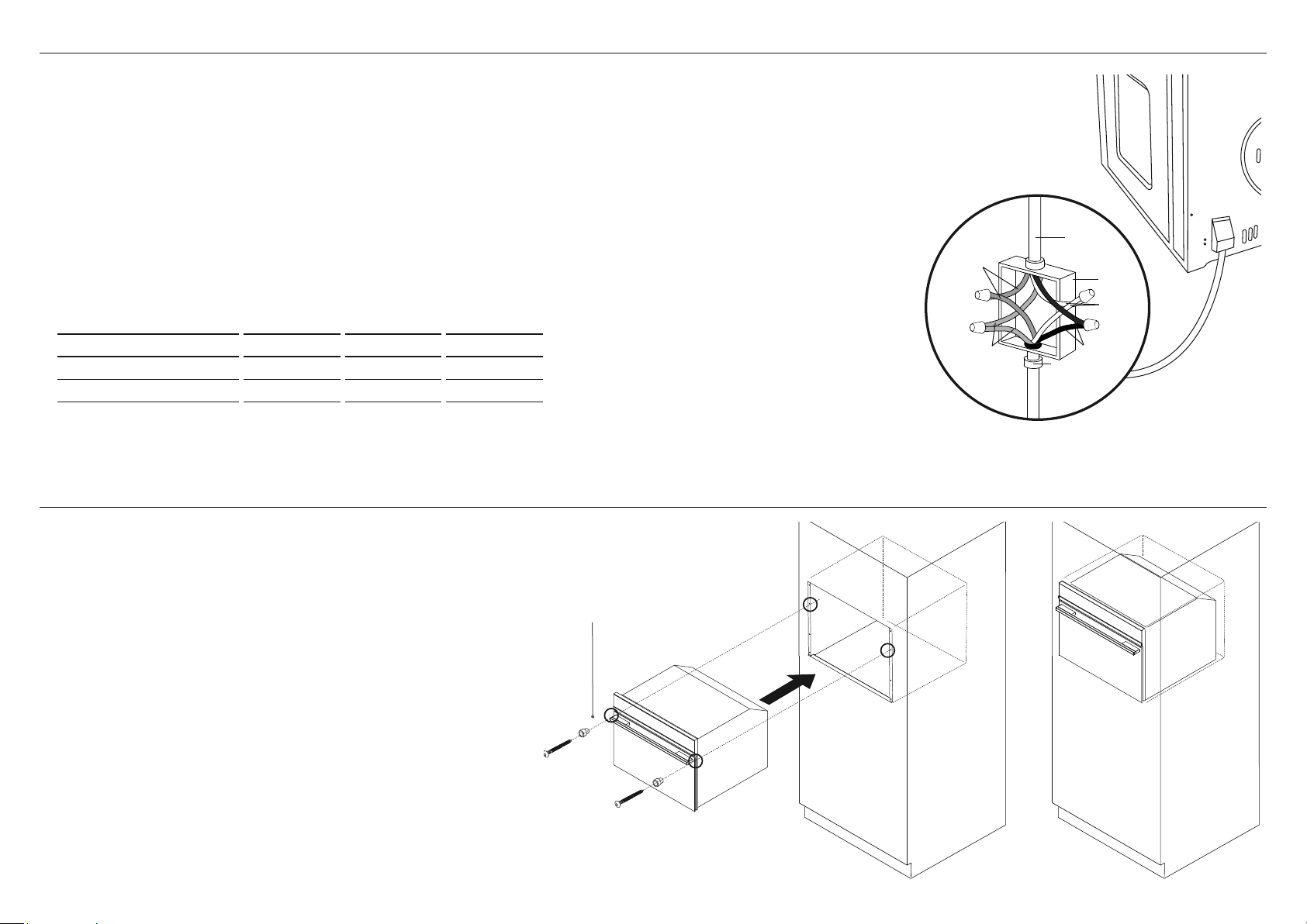
34 | FOUR À MICRO-ONDE GUIDE D’INSTALLATION
7 FIXEZ LE FOUR AUX ARMOIRES
1 Placez le four dans la cavité préparée.
IMPORTANT!
Ne soulevez pas le four par la poignée de la porte.
2 Utilisez les vis et les entretoises fournies pour fixer le four aux armoires.
IMPORTANT!
●
Ne serrez pas trop les vis.
●
Veillez à ne pas endommager la partie inférieure du four.
●
Ne pas sceller le four dans les armoires avec du silicone ou de la colle.
Cela rend l’entretien ultérieur difficile. Fisher & Paykel ne couvrira pas
les coûts d’enlèvement du four, ou des dommages causés par ce retrait.
S’assurer que l’entretoise
fournie est installée entre
le four et les armoires
Avant de vous connecter à l’électricité, assurez-vous que:
●
les spécifications du système électrique correspondent à ce qui est détaillé sur cette section. (Fig. 1)
●
le système a une connexion au sol efficace conforme aux normes et lois en vigueur.
La connexion au sol est requise par la loi. Le câble ne doit à aucun moment atteindre une température supérieure à 122 ° F (50 °
C) au-dessus de la température ambiante.
Ce four doit être connecté à l’électricité par un câble d’alimentation et une fiche compatible avec la sortie du système électrique
qui alimente ce four. Si un appareil fixe n’a pas de cordon d’alimentation et de prise, ou un autre appareil qui assure une
déconnexion
du secteur, avec une distance d’ouverture des contacts qui permet une déconnexion complète, de tels dispositifs de déconnexion
doivent être prévus dans le réseau d’alimentation conforme à l’installation règles.
La prise ou l’interrupteur omnipolaire doit être facile à atteindre lorsque l’appareil est installé.
Remarque: Le fabricant décline toute responsabilité si les normes habituelles de prévention des accidents et les instructions
ci-dessus ne sont pas respectées.
6 BRANCHEMENT ÉLECTRIQUE
connecteur de
conduit
homologué UL
boîte de
câblage
mural
câble
d’alimentation
électrique
fils rouges
fils blancs
fils verts de mise
àla terre du four -
regroupés en usine
fils noirs
Fig. 1
MAXIMUM D’ÉNERGIE (W) HZ VOLTAGE (V) AMPS (A)
3400 60 Hz 120/240 14
2700 60 Hz 120/208 13

FOUR À MICRO-ONDE GUIDE D’INSTALLATION | 35
8 LISTE DE CONTRÔLE FINALE
A REMPLIR PAR L’INSTALLATEUR
F Assurez-vous que le four est de niveau et solidement fixé aux armoires.
F Vérifiez que la garniture inférieure n’est pas endommagée.
F Ouvrez lentement la porte du four jusqu’à ce qu’elle soit complètement ouverte et vérifiez qu’il y a un espace suffisant entre le bas de la porte et la garniture inférieure.
Ceci afin d’assurer une circulation d’air correcte. Si les moulures inférieures sont endommagées, redressez la moulure et assurez-vous que la porte du four s’ouvre
complètement sans obstruction.
F Assurez-vous que les attaches de câbles et l’emballage interne ont été retirés de la cavité du four.
F Assurez-vous que tous les évents et les ouvertures du four sont dégagés et qu’ils ne sont pas obstrués ou endommagés.
IMPORTANT!
Si vous ne vous assurez pas que toutes les fentes d’aération du four sont dégagées, la performance du produit peut être médiocre.
F Assurez-vous que l’interrupteur d’isolement est accessible au client.
OPERATION DE TEST:
F Avez-vous démontré l’opération de base au client?
Reportez-vous au Guide de l’utilisateur.
Compléter et conserver pour référence sûre:
Modèle
Numéro de série
Date d’achat
Acheteur
Adresse du concessionnaire
Nom de l’installateur
Signature de l’installateur
Compagnie d’installation
Date d’installation
© Fisher&Paykel Appliances 2020. Tous droits réservés.
Les caractéristiques de produit présentées dans ce document
s’appliquent aux modèles et produits spécifiques qui y sont décrits à la
date de publication. Dans le cadre de notre politique d’amélioration en
permanence de nos produits, ces caractéristiques peuvent être modifiées
à tout moment. Nous vous recommandons de vérifier auprès de votre
détaillant que ce document décrit le produit actuellement disponible.
Pour les plus récentes informations sur la disponibilité des modèles et des
caractéristiques dans votre pays, visitez notre site Web fisherpaykel.com
ou contactez votre détaillant Fisher&Paykel local.
FISHERPAYKEL.COM