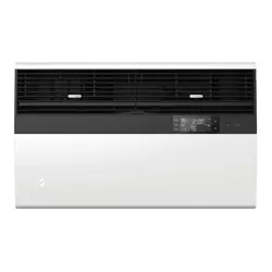
User Manual Friedrich SQ08N10C Window or Wall Air Conditioner Cooling Area
Installation Instructions
CIRCUIT PROTECTION – Use on single outlet circuit only. An overloaded circuit will invariably cause malfunction or failure of an air conditioner, therefore, it is necessary that the electrical protection is adequate. Due to momentary high current demand when the air conditioner starts, use a "TIME DELAY" fuse or a HACR type circuit breaker. Consult your dealer or power company if in doubt.
Refer to the electrical name plate located on the air conditioner chassis (See page 2) to determine the correct fuse or circuit breaker amperage for your model (See Table 1 on Page 6 for electrical receptacle types)
The power cord has a plug with a grounding prong and a matching receptacle is required.
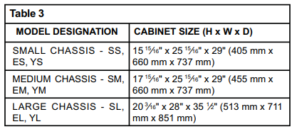
The following instructions are for standard chassis model groups distinguished by the first two letters of the model designations and cabinet sizes listed in Table 3.
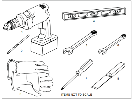
Recommended Tools
1. Power Drill
2. 5/32" Drill Bit
3. Gloves
4. Carpenters Level
5. 5/16" Wrench
6. 1/4" Wrench
7. #2 Phillips Screw Driver
8. Putty Knife or (wood stir stick)
INSTALLATION HARDWARE AND ACCESSORY DETAIL
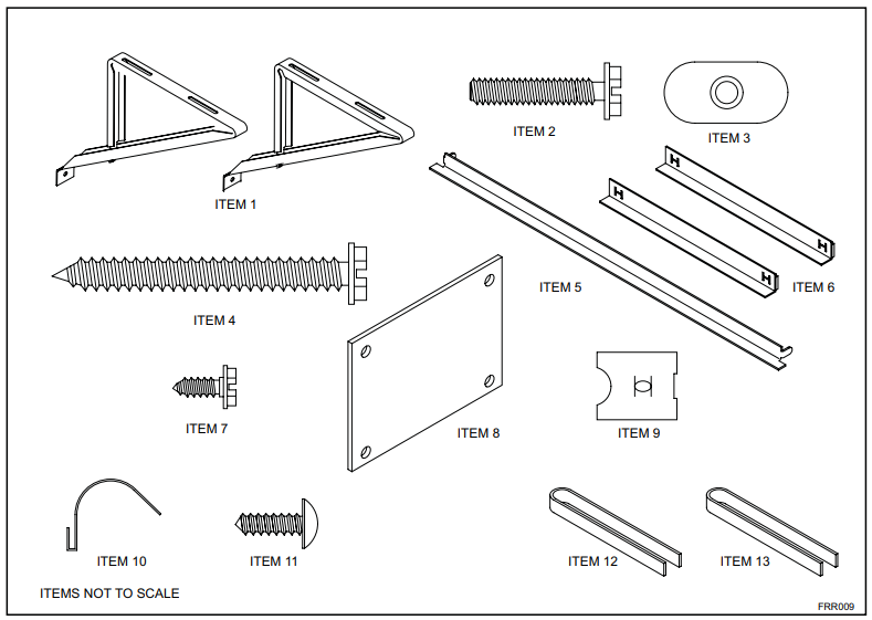
Window Mount Installation Hardware
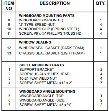
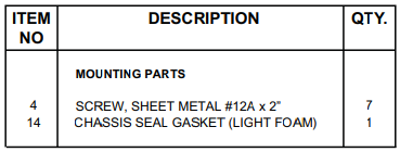
Thru-the-wall Installation Hardware
Standard Window Installation
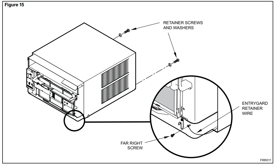
STEP 1.
Remove the chassis Entrygard retainer by removing the far right screw (See Figure 15), save this screw to reattach the chassis retainer after installation (Step 12). Also, remove and discard the two retainer screws and washers located at the rear of the unit (See Figure 15).
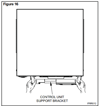
STEP 2.
Hold the cabinet stationary, then use the hand grips on both ends of the control unit support bracket to pull the chassis out of the cabinet (See Figure 16).
STEP 3.
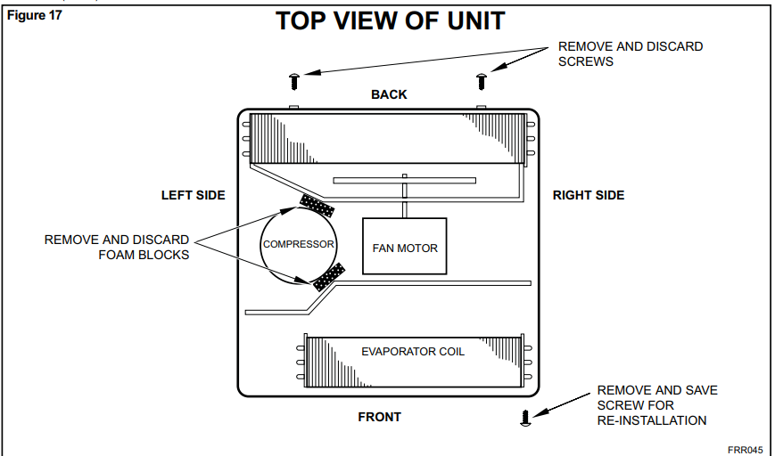
Remove the large white foam blocks used to restrain the compressor during shipment (See Figure 17). Inspect base pan for dislodged white foam blocks and remove. Do not remove any other foam parts.
STEP 4.
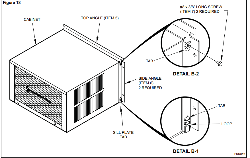
Anchor the side angles (Item 6) by engaging the tabs of the lower sill plate (See Figure 18, Detail B-2) with the loops of the side angle. Engage the tabs of the top angle (Item 5) with the top loops of the side angle (See Figure 18, Detail B-1). Install two (2) screws (Item 7) to secure the top angle tabs and the side angle to the cabinet (See Figure 18, Detail B-1).
STEP 5.
Check the window sill and frame to be sure they are in good condition and firmly anchored to the wall. Repair if necessary
STEP 6. CABINET MOUNTING
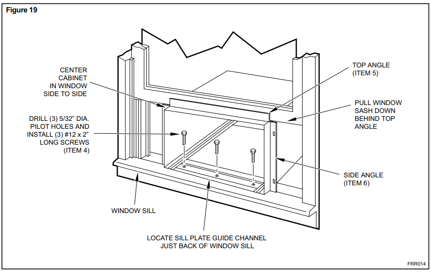
Raise the lower window 1/4" more than the height of the cabinet. Carefully slide the cabinet through the opening until the lower sill plate channel rests behind the window sill and the top angle rests against the window (See Figure 19). Center the cabinet within the opening. Drill three (3) 5/32" diameter pilot holes into window sill using the holes in the cabinet sill plate as a guide. Install three (3) #12 x 2" long screws (Item 4) (See Figure 19)
STEP 7.
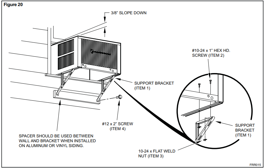
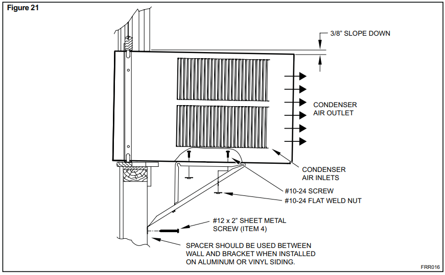
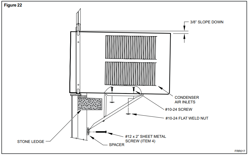
OUTSIDE SUPPORT MOUNTING – Refer to Figures 20 and 21. Assemble the support brackets (Item 1) to the bottom of the cabinet with four (4) 10-24 1” long screws (Item 2) and four 10-24 flat nuts (item 3 ). Adjust the support brackets, using a combinations of the elongated holes of the bracket and different hole locations in the cabinet, to bring the bottom support bracket pads in contact with the wall. A 1" x 4" or 2" x 4" SPACER SHOULD BE USED BETWEEN THE WALL AND SUPPORT THE BRACKETS WHEN INSTALLED ON ALUMINUM OR VINYL SIDING. Drill 5/32" diameter pilot holes and secure the brackets to the wall with two (2) 12A x 2" long screws (Item 4)
Adjust the support brackets to provide an inside-to-outside slope for excess condensation drainage (Refer to Standard Window Installation, Figures 20 through 24). Tighten all screws.
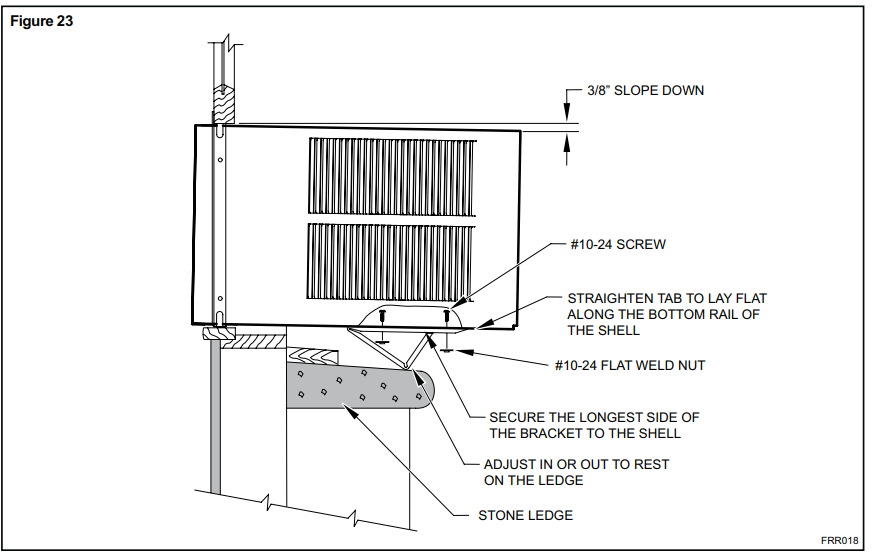
Alternate support method A: If you have a wide window sill which prevents you from mounting the brackets as shown in Figure 23. try the folowing:
Using the elongated holes and different hole locations in the cabinet. set the placement of the bracket to support the unit's weight (Figure 23).
Tighten all screws.
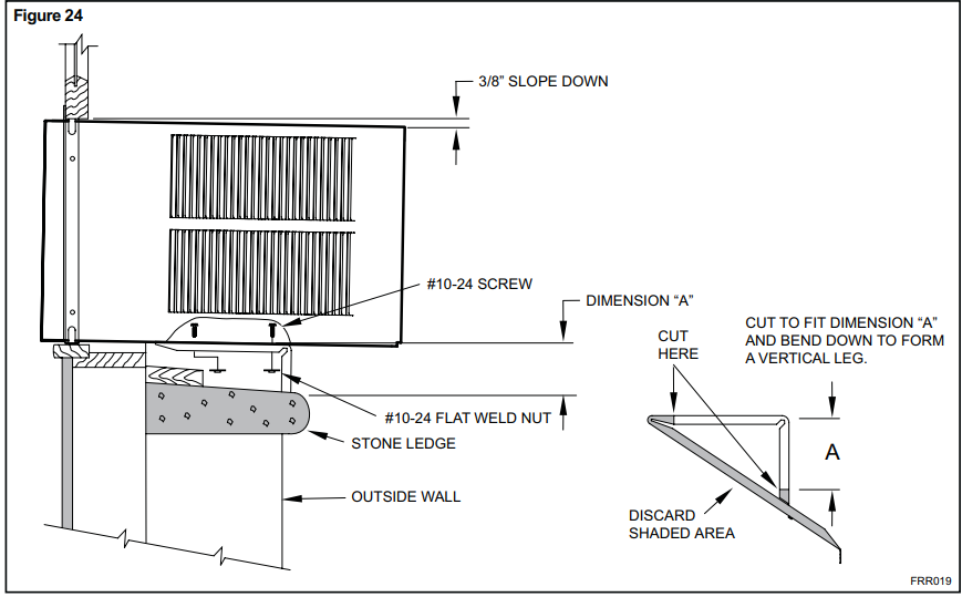
Alternate support method B: If the window ledge gap is narrow. try the following. Bend the bracket end tab flat. Cut the bracket in two (2) places as shown in Figure 24. Bend the short piece so it will be vertical when installed. Adjust the placement as required. Tighten all screws.
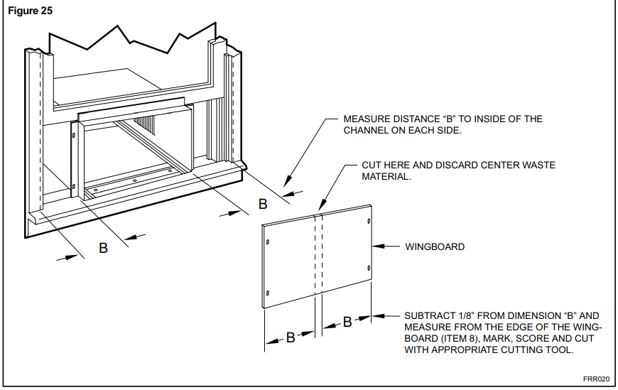
STEP 8.
Measure and cut the wingboard panels (it with about 1/8" clearance) from the supplied Masonite Item 8) tofitthe space between the window side channels and cabinet. (Figure 25).
Make sure you include the depth of the window channel.
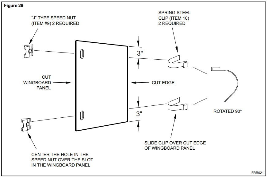
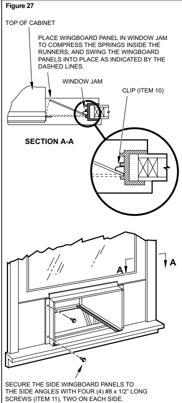
STEP 9
To assemble the wingboard panels. push on the "J" type speed nuts (Item 9) and spring stee! clips (Item 10) (See Figures 26) on page 31. Secure each panel with two (2) screws (Item 11).
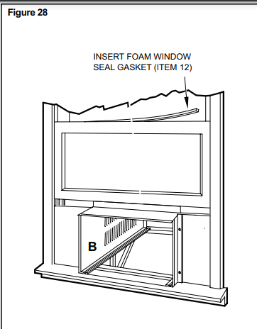
STEP 10.
INSTALL THE WINDOW SEALING GASKETS – Measure and cut the dark foam window seal gasket (Item 12) and install it between the upper glass panel and the top part of the window sash (Figure 28).
STEP 11.
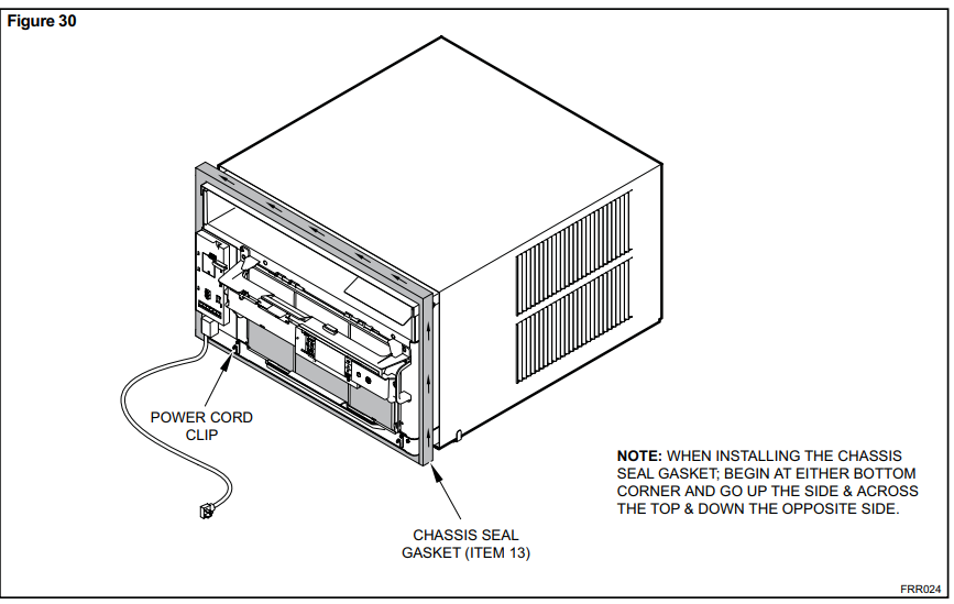
Carefully team lift the chassis and set it into the cabinet. Slide the chassis stopping approximately 3" from full insertion. Insert the chassis seal gasket (Item 13) one inch deep between the chassis and the cabinet (See Figure 30) as shown on page 33. A paint stir stick or ruler might be helpful here. Begin inserting the gasket at either bottom corner and go up the side, across the top, and down the opposite side. Then push the chassis all the way into the cabinet.
STEP 12.
Reattach the entry guard chassis entry guard retainer wire with the same screw retained in Step 1 (See Figure 15).
STEP13.
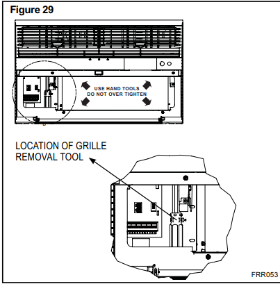
To attach and prevent damage to the front grille align the cord notch over the cord and center the fresh ar lever. then align and tighten the four (4) captive screws as indicated by the arrows in Figure 29. Before closing the front panel. be sure the filter is in place. Make sure curtains do not block the side ar intakes.
STEP 14.
Refer to the Control Panel Operation section for instructions.
STEP 15.
You are now ready to control the comfort level of the room.
Use Tool Provided
Please use the provided tool to attach the decorative front to the chassis.
Cord Routing Change
Unplug unit.
For convenience and optimum appearance the direction that the power cord exits the unit may be changed from left to right by following the procedure below. Select the exit location on the left or right based on proximity to the power outlet.
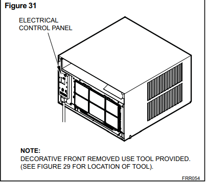
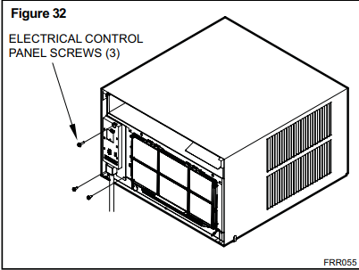
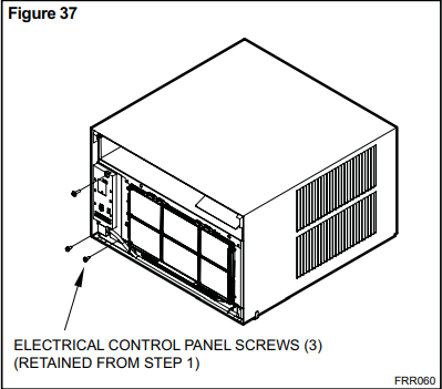
Remove 3 screws as shown from the electrical control panel. Save to reinstall later.
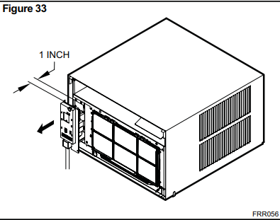
STEP 16.
Carefully pull out electrical control panel 1", but not all the way.
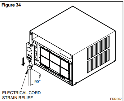
STEP 17.
Pull electrical cord strain relief downward until free and rotate 90 degrees to the right.
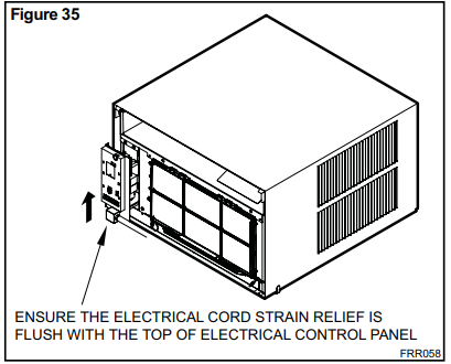
STEP 18.
Push electrical cord strain relief back upward into the electrical control panel.
STEP 19
Carefully push electrical control panel back into chassis.
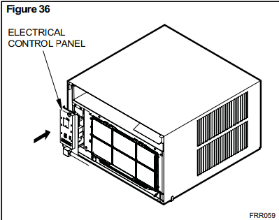
STEP 20.
Reinstall the 3 screws removed earlier to secure electrical control panel.
STEP 21.
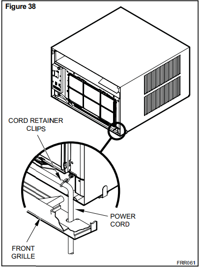
If running power cord to the right of the unit install the cord into the cord retainer clips along the bottom front of the unit.
Final Inspection & Start-up Checklist
+ Inspect and ensure that all components and accessories have been installed properly and that they have not been damaged during the installation progress.
+ Check the condensate water drain(s) to ensure that they are adequate for the removal of condensate water. and that they meet the approval of the end user.
+ Ensure that all installation instructions concerning clearances around the unit have been adhered to. Check to ensure that the unit air filter. indoor coil. and outdoor coils are free from any obstructions.
+ Ensure that the circuit breaker(s) or fuse(s) and supply circuit wire size have been sized correctly. If the unit was supplied with a power supply cord. insure that it is stored properly.
+ Ensure that the entire installation is in compliance with all applicable national and local codes and ordinances having jurisdiction.
+ Secure components and accessories. such as a decorative front cover.
+ Start the unit and check for proper operation of all components in each mode of operation.
+ Instruct the owner or operator of the units operation. and the manufacturer's Routine Maintenance.
+ Present the owner or operator of the equipment with the Installation & Operation Manual, all accessory installation instructions, and the name, address and telephone number of the Authorized Friedrich Warranty Service Company in the area for future reference if necessary.
This is a warm weather appliance
Your air conditioner is designed to cool in warm weather when the outside temperature is above 60° F (15.6° C) and below 115° F (46.1° C), so it won't cool a room if it is already cool outside. If you want to cool a room in the spring or fall, select the FAN ONLY mode and set the Fresh Air/Exhaust air control to Fresh Air. This will bring in a supply of cooler outside air.
Condensation is normal
Air conditioners actually pump the heat and humidity from your room to the outside. Humidity becomes water, and your air conditioner will use most of the water to keep the outside coil cool. If there is excessive humidity, there may be excess water that will drip outside. This is normal operation.
Frosting
This usually occurs because of insufficient airflow across the coils. a dirty fit. cool damp weather. oral ofthese. Set the SYSTEM mode to FAN
ONLY Band the frost will disappear. Setting the thermostata litte warmer will probably prevent the frosting from recurring.
Noises
All air conditioners make some noise. Friedrich units are designed to operate as quietly as possible. An air conditioner mounted in a wall is quieter than one mounted in a window. It is important to ensure that the chassis seal gasket (Item 13) is properly installed (refer to installation instructions).
Heat pumps operate differently
If your unit is a "Y", or heat pump model, there are some things that you will want to be aware of. Some functions of a heat pump differ from your unit when it is used for heating
- Its normal for ice to form on the outdoor coil of the heat pump.
Moisture in the outside air. passing over the coil when very cold. will form ice.
- If the outdoor temperature drops below 37° F (3° C), your heat pump will automatically turn on the electric resistance heat. When the temperature rises to 40° F (4° C), the compressor will resume the heat pump operation. If your unit is a 115 volt model (YS10), it is designed for use in warmer climates and does not have an electrical heat feature, and will not provide adequate heat below 37° F (2.8° C)