
Owner's Manual
ICRAFTSMAN°J
25.0 HP
ELECTRIC START
48" MOWER
AUTOMATIC
GARDEN TRACTOR
Model No.
917.275221
• Safety
• Assembly
• Operation
• Maintenance
• Repair Parts
CAUTION:
Read and follow all Safety
Rules and Instructions before
operating this equipment.
For answers to your questions
about this product, Call:
1-800-659-5917
Sears Craftsman Help Line
5 am - 5 pro, Mon- Sat
Sears, Roebuck and Co., Hoffman Estates, II 60179
Visit our Craftsman website:www.sears.com/craftsman
Warranty...............................................2
Safety Rules ......................................... 3
Product Specifications .......................... 6
Assembly .............................................. 9
Operation ............................................ 14
Maintenance Schedule ...................... 21
Maintenance ....................................... 21
Service and Adjustments .................... 25
Storage ............................................... 33
Troubleshooting ................................. 34
Repair Parts ........................................ 38
Parts Ordering ..................... Back Cover
LIMITED TWOYEAR WARRANTY ON CRAFTSMAN RIDING EQUIPMENT PARTS
For two (2) years from the date of purchase, if this Craftsman Riding Equipment Ls
maintained, lubricated and tuned up according to the instructionsin the owner's
manual, Sears will repair or replace, free of charge, any parts found to be defective in
material or workmanship. Warranty service is available free of charge by returning your
Craftsman riding equipment to your nearest Sears Service Center. In-home warranty
service is available but a trip charge will apply. This warranty applies only while this
product isin the United States.
This Warranty does not cover:
• Expendable items which become worn during normal use, such as blades, spark
plugs, air cleaners, belts and oil filters.
• Tire replacement or repair caused by punctures from outside objects, such as nails,
thorns, stumps, or glass.
• Repairs necessary because of operator abuse, including but not limited to, damage
caused by towing objects beyond the capability of the riding equipment, impacting
objects that bend the frame or crankshaft, or over speeding the engine.
• Repairs necessary because of operator negligence, including but not limited to,
electdcal and mechanical damage caused by improper storage, failure to use the
proper grade and amount of engine oil, failure to keep the deck clear of flammable
debris, or the failure to maintain the equipment according to the instructions con-
tained in the owner's manual.
• Engine (fuel system) cleaning or repairs caused by fuel determined to be contami-
nated or oxidized (stale). In general, fuel should be used within thirty (30) days of its
purchase date.
• Riding equipment used for commercial or rental purposes. A product is "used for
commercial purpose" if is used for any purpose other than single family household
dwellings or in usage where profit is made.
LIMITED 90 DAY WARRANTY ON BATTERY
For ninety (90) days from date of purchase, if any battery included with this riding
equipment proves defective in material or workmanship end our testing determines the
battery will not hold a charge, Sears will replace the battery at no charge. Warranty
service is available free of charge by returning your Craftsman riding equipment to
your nearest Sears Service Center. In-home warranty service is available but a trip
charge will apply. This warranty applies only while this product is in the United States.
TO LOCATE THE NEAREST SEARS SERVICE CENTER OR TO SCHEDULE IN-HOME
WARRANTY SERVICE, SIMPLY CONTACT SEARS AT 1-80O-4-MY-HOME
This Warranty gives you specific legal rights, and you may also have other rights which
may vary from state to state.
Sears, Roebuck and Co., D/817 WA, Hoffman Estates, IL 60179
IMPORTANT: This cutting machine is capable of amputating hands and feet and
throwing objects. Failure to observe the following safety instructionscould result in
serious injury or death.
I. GENERAL OPERATION
• Read, understand, and follow all
instructionsin the manual and on the
machine before starting.
• Only allow responsible adults, who are
familiar with the instructions,to operate
the machine.
• Clear the area of objects such as
rocks,toys, wire, etc., which could be
picked up and thrown by the blade.
• Be sure the area is clear of other
people before mowing. Stop machine
ifanyone enters the area.
• Never carry passengers.
• Do not mow in reverse unless abso-
lutely necessary. Always lookdown
and behind before and while backing.
• Be aware of the mower discharge
directionand do not point it at anyone.
Do not operate the mower without
either the entire grass catcher or the
guard in place.
• Slow down before turning.
• Never leave a running machine
unattended. Always tum off blades, set
parking brake, stop engine, and
remove keys before dismounting.
• Turn off blades when not mowing.
• Stop engine before removing grass
catcher or unclogging chute.
• Mow only in daylight or good artificial
light.
• Do not operate the machine while
under the influence of alcohol or drugs.
• Watch for traffic when operating near or
crossing roadways.
• Use extra care when loading or
unloading the machine into a trailer or
truck.
• Data indicates that operators, age 60
years and above, are involved in a
large percentage of riding mower-
related injuries. These operators
should evaluate their ability to operate
the riding mower safely enough to
protectthemselves and others from
serious injury.
II. SLOPE OPERATION
Slopes are a majorfactor related to loss-of-
control and tipover accidents, which can
result in severe injury or death. All slopes
require extra caution. Ifyou cannot backup
the slope or ifyou feel uneasy on it, do not
mow it.
DO:
• Mow up and down slopes, not across.
• Remove obstacles such as rocks, tree
limbs, etc.
• Watch for holes, ruts, or bumps.
Uneven terrain coutd overtum the
machine. Tallgrass can hide ob-
stacles.
• Use slow speed. Choose a low gear
so that you will not have to stop or shift
while on the slope.
• Follow the manufacturer's recommen-
dations for wheel weights or counter-
weights to improve stability.
• Use extra care with grass catchers or
other attachments. These can change
the stability ofthe machine.
• Keep all movement on the slopes s/ow
and gradual. Do not make sudden
changes in speed or direction.
• Avoid starting or stoppingon a slope. If
tires lose traction, disengage the
blades and proceed slowly straight
down the slope.
DO NOT:
• Do not turn on slopes unless neces-
sary, and then, turn slowly and gradu-
ally downhill, if possible.
• Do notmow near drop-offs, ditches, or
embankments. The mower could
suddenly turn over if a wheel is over
the edge of a cliff or ditch,or ifan edge
caves in.
• Donotmowonwetgress. Reduced
traction could cause sliding.
• Do not try to stabilize the machine by
puttingyour foot on the ground.
• Do notuse grass catcher on steep
slopes.
3
Ill. CHILDREN
Tragicaccidents can occur if the operator
is not alert to the presence of children.
Children are often attracted to the
machine and the mowing activity. Never
assume that children will remain where
you lastsaw them.
• Keep children out of the mowing area
and under the watchful care of another
responsible adult.
• Be alert and turn machine off ifchildren
enter the area.
• Before and when backing, look behind
and down for small children.
• Never carry children. They may fall off
and be seriously injured or interfere
with safe machine operation.
• Never allow children to operate the
machine.
• Use extra care when approaching blind
corners, shrubs, trees, or other objects
that may obscure vision.
IV. SERVICE
• Use extra care in handling gasoline
and other fuels. They are flammable
and vapors are explosive.
-Use only an approved container.
-Never remove gas cap or add fuel
with the engine running. Allow
engine to cool before refueling. Do
not smoke.
-Never refuel the machine indoors.
-Never store the machine or fuel
container inside where there is an
open flame, such as a water heater.
• Never run a machine inside a closed
area.
• Keep nuts and bolts, especially blade
attachment bolts, tight and keep
equipment in good condition.
• Never tamper with safety devices.
Check their proper operation regularly.
• Keep machine free of grass, leaves, or
other debris build-up. Clean oil or fuel
spillage. Allow machine to cool before
storing.
• Stop and inspect the equipment if you
strike an object. Repair, if necessary,
before restarting.
• Never make adjustments or repairs
with the engine running.
• Grass catcher components are subject
to wear, damage, and deterioration,
which could expose moving parts or
allow objects to be thrown. Frequently
check components and replace with
manufacturer's recommended parts,
when necessary.
• Mower blades are sharp and can cut.
Wrap the blade(s) or wear gloves, and
use extra caution when servicing them.
• Check brake operation frequently.
Adjust and service as required.
• Be sure the area is clear ofother
people before mowing. Stop machine if
anyone enters the area.
• Never carry passengers or children
even with the blades off.
• Do not mow in reverse unless abso-
lutely necessary. Always look down
and behind before and while backing.
• Never carry children. They may fall off
and be seriously injured or interfere
with safe machine operation.
• Keep children out of the mowing area
and under the watchful care of another
responsible adult.
• Be alert and turn machine off if children
enter the area.
• Before and when backing, look behind
and down for small children.
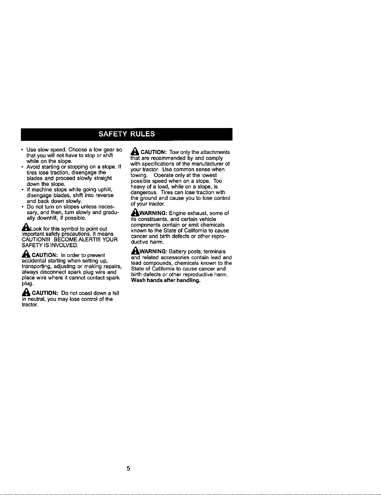
• Mow up and down slopes (15° Max),
not across.
• Remove obstacles such as rocks, tree
limbs,etc.
• Watch for holes, ruts, or bumps.
Uneven terrain could overturn the
machine. Tall grass can hide obstacles.
4
• Use slow speed. Choose a low gear so
that you will not have to stop or shift
while on the slope.
• Avoid starting or stoppingon a slope. If
tires lose traction, disengage the
blades and proceed slowly straight
down the slope.
• If machine stops while going uphill,
disengage blades, shift into reverse
and back down slowly.
• Do not turn on slopes unless neces-
sary, and then, turn slowly and gradu-
ally downhill, if possible.
_Look for this symbol to point out
important safety precautions. It means
CAUTIONf!! BECOMEALERTt!! YOUR
SAFETY IS iNVOLVED.
_ CAUTION: In order to prevent
accidental starting when setting up,
transporting, adjusting or making repairs,
always disconnect spark plug wire and
place wire where it cannot contact spark
plug.
,_ CAUTION: Do not coast down a hill
in neutral, you may lose control of the
tractor.
A
Mi, CAUTION: Tow only the attachments
that are recommended by and comply
with specificationsofthe manufacturer of
your tractor. Use common sense when
towing. Operate only at the lowest
possible speed when on a slope. Too
heavy of a load, while on a slope, is
dangerous. Tires can lose traction with
the ground and cause you to lose control
of yourtractor.
_IWARNING: Engine exhaust, some of
its constituents,and certain vehicle
components contain or emit chemicals
known to the State of California to cause
cancer and birthdefects or other repro-
ductive harm.
_WARNING: Battery posts, terminals
and related accessories contain lead and
lead compounds, chemicals known to the
State of California to cause cancer and
birthdefects or other reproductive harm.
Wash hands after handling.
5
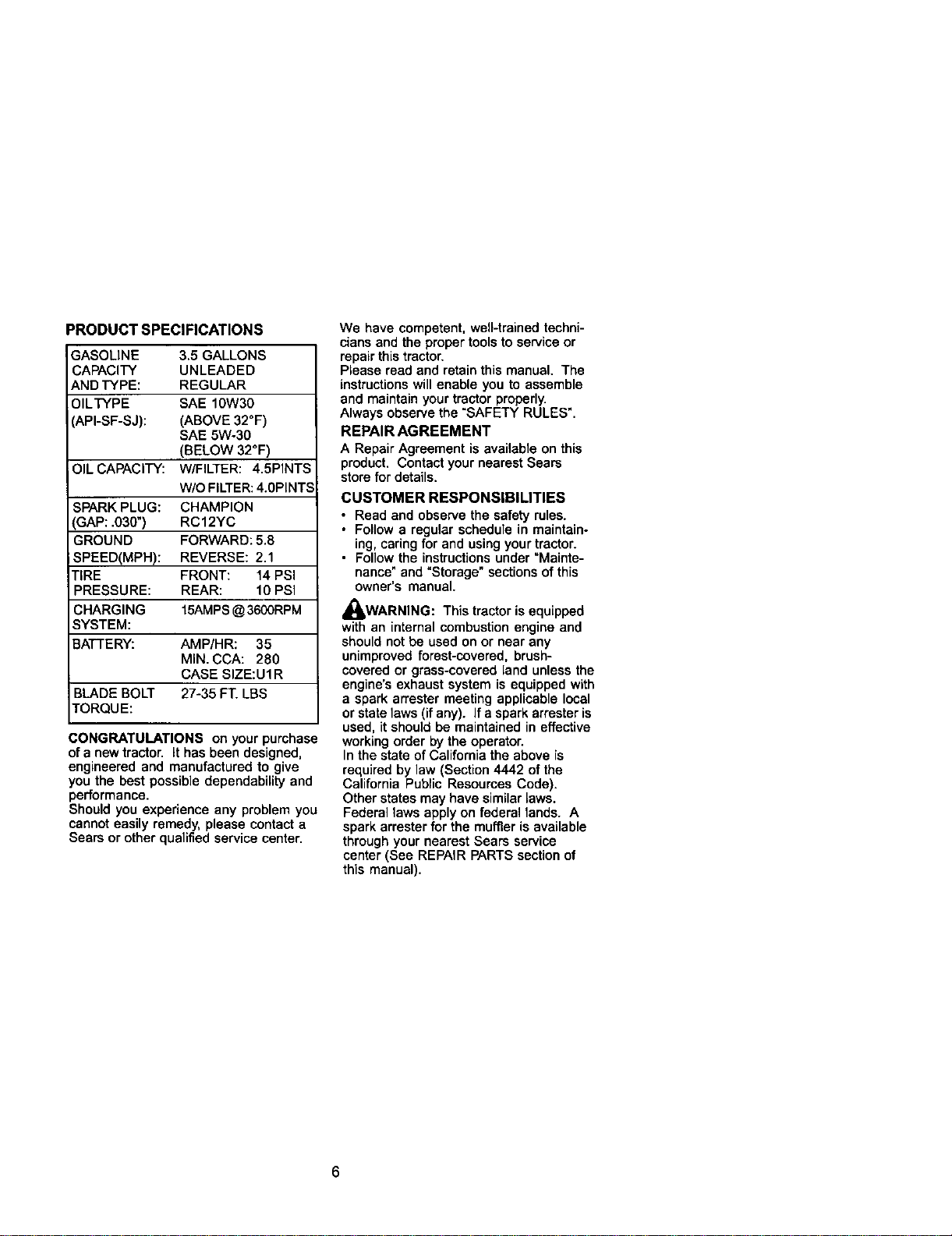
_RODUCT SPECIFICATIONS
GASOLINE 3,5 GALLONS
CAPACITY UNLEADED
AND TYPE: REGULAR
OILTYPE SAE 10W30
_Pt-SF-SJ): (ABOVE 32°F)
SAE 5W-30
(BELOW 32°F)
OILCAPACITY: W/FILTER: 4.5PINTS
W/O FILTER:4.0PINTS
._PARK PLUG: CHAMPION
GAP: .030 ) RC12YC
GROUND FORWARD: 5.8
SPEED(MPH): REVERSE: 2.1
T_RE FRONT: 14 PSi
PRESSURE: REAR: 10 PSi
CHARGING 15AMPS@ 3600RPM
SYSTEM:
BATTERY: AMP/HR: 35
MIN. CCA: 280
CASE SIZE:U1R
BLADE BOLT 27-35 FT. LBS
TORQUE:
CONGRATULATIONS on your purchase
of a new tractor, it has been designed,
engineered and manufactured to give
you the best possible dependability and
performance.
Should you experience any problem you
cannot easily remedy, please contact a
Sears or other quali_ed service center.
We have competent, well-trained techni-
cians and the proper tools to service or
repair this tractor.
Please read and retain this manual. The
instructions will enable you to assemble
and maintain your tractor properly.
Always observe the "SAFETY RULES".
REPAIR AGREEMENT
A Repair Agreement is available on this
product. Contact your nearest Sears
stere for details.
CUSTOMER RESPONSIBILITIES
• Read and observe the safety rules.
• Follow a regular schedule in maintain-
ing, caring for and using your tractor.
• Follow the instructions under "Mainte-
nance" and "Storage" sections of this
owner's manual.
_IjWARNING: This tractor is equipped
with an internal combustion engine and
should not be used on or near any
unimproved forest-covered, brush-
covered or grass-covered land unless the
engine's exhaust system is equipped with
a spark arrester meeting applicable local
or state laws (if any). If a spark srrester is
used, it should be maintained in effective
working order by the operator.
In the state of California the above is
required by law (Section 4442 of the
California Public Resources Code).
Other states may have similar laws.
Federal laws apply on federal lands. A
spark arrester for the muffler is available
through yournearest Seers service
center (See REPAIR PARTS section of
this manual).
6
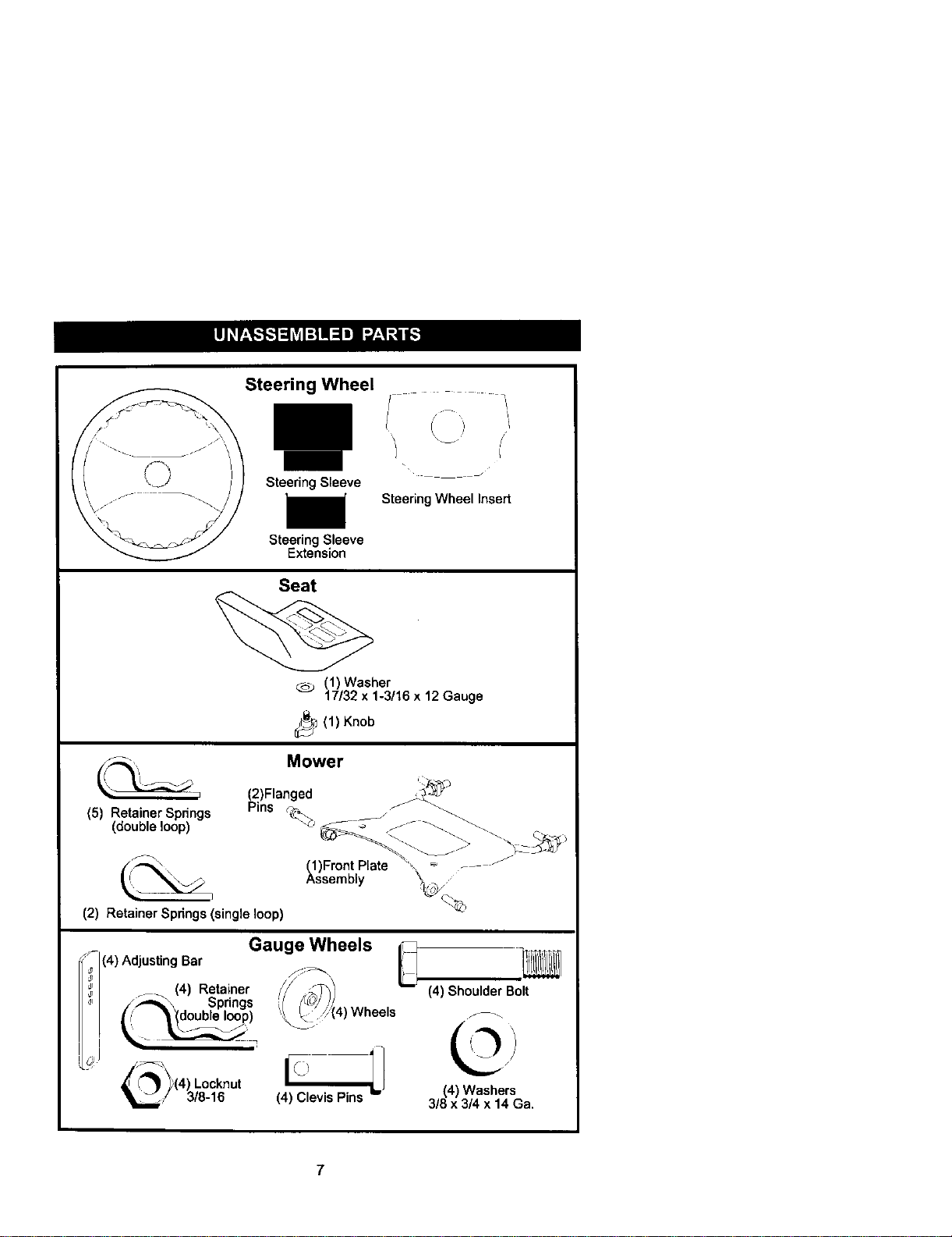
Steering Wheel
I
Steering Sleeve
ii
Steering Sleeve
Extension
Seat
,/
I i'
\
_ J•
Steering Wheel Insert
(1)Washer
17132x 1-3/16x 12 Gauge
_1(1) Knob
Mower
(5) Retainer Springs
(double loop)
_.2)Flanged
.,ns
(1)Front Plate
Assembly
(2) Retainer Spdngs (single loop)
Gauge Wheels
C4)Adjusting Bar _' J
LJ
_ (4) Retainer
,/_,_" Springs
_( _ (double loop)
L_'_\_(4 )Locknut
/ 3/8-16
Wheels
(4) Clevis Pins
(4) Shoulder Bolt
(4) Washers
3/8 x 3/4 x 14 Ga.
7
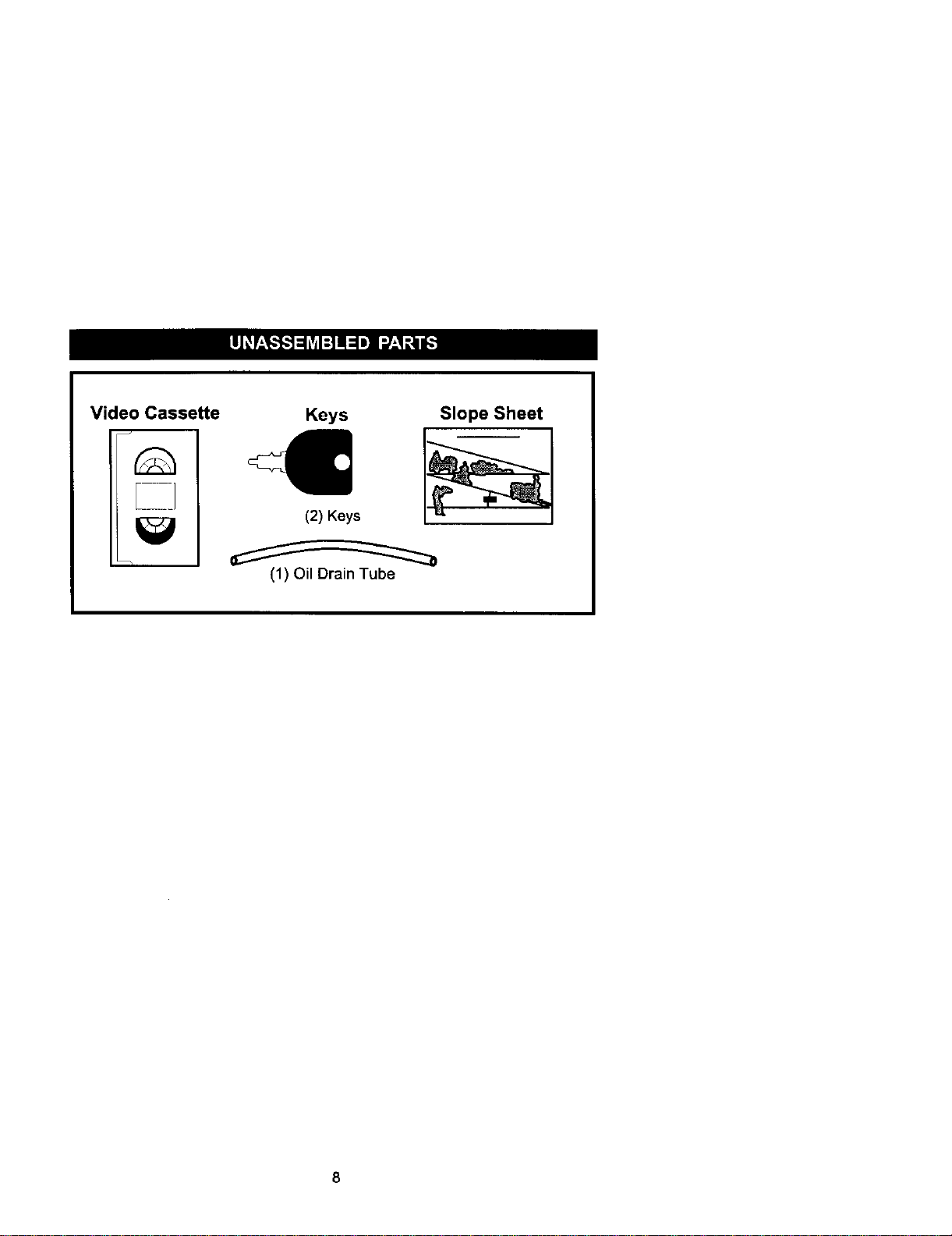
Video Cassette
Keys
(2) Keys
Slope Sheet
(1) Oil Drain Tube
Your new tractorhas been assembled at the factory with exception of those parts left
unassembled for shipping purposes. To ensure safe and proper operation of your
tractor all parts and hardware you assemble must be tightened securely. Use the
correct tools as necessary to insure proper tightness.
TOOLS REQUIRED FOR
ASSEMBLY
A socket wrench set will make assembly
easier. Standard wrench sizes you need
are listed below.
(1) 9/16"wrench (1) Pliers
(1) 1/2"wrench (1) Utility knife
(1) 3/4" socketwith
drive ratchet
(1) Tire pressure gauge
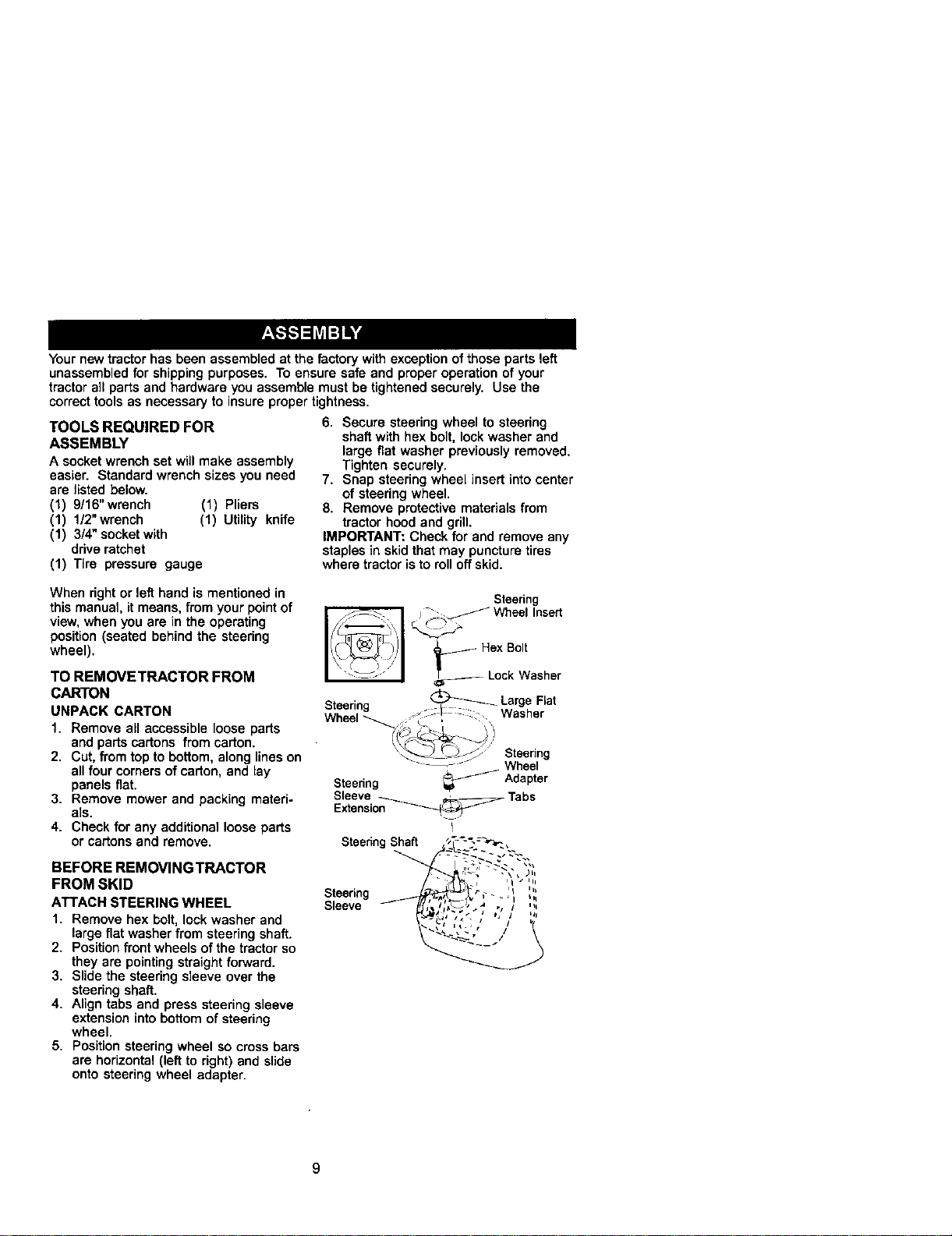
6. Secure steering wheel to steering
shaft with hex bolt, lock washer and
large flat washer previously removed.
Tighten securely.
7. Snap steering wheel insert into center
of steering wheel.
8. Remove protective materials from
tractor hood and grill.
IMPORTANT: Check for and remove any
staples in skid that may puncture tires
where tractor is to roll off skid.
When right or left hand is mentioned in
this manual, it means, from your pointof
view, when you are in the operating
position (seated behind the steering
wheel).
TO REMOVETRACTOR FROM
CARTON
UNPACK CARTON
1. Remove all accessible loose parts
and parts cartons from carton.
2. Cut, from top to bottom, along lines on
all four cornersof carton, and lay
panels flat.
3. Remove mower and packing materi-
als.
4. Check for any additional loose parts
or cartons and remove.
BEFORE REMOVINGTRACTOR
FROM SKID
ATTACH STEERING WHEEL
1. Remove hex bolt, lock washer and
large fiat washer from steering shaft.
2. Position front wheels of the tractor so
they are pointingstraightforward.
3. Slide the steering sleeve over the
steering shaft.
4. Align tabs and press steering sleeve
extension intobottom of steering
wheel.
5. Position steering wheel so cross bars
are horizontal (left to right) and slide
onto steering wheel adapter.
Steering
Wheel Insert
Steering
Wheel
Hex Bolt
Lock Washer
_ Large Flat
_;: :::: - Washer
Steering
Wheel
Steedng _ Adapter
Sleeve Tabs
Extensio__
SteeringShaft
Steering ' '"
Sleeve , / ,,,
9
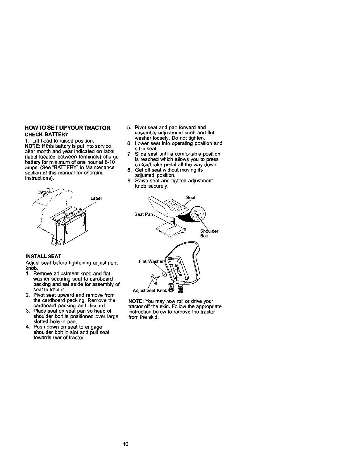
HOWTO SET UPYOURTRACTOR
CHECK BATTERY
1. Lift hood to raised position,
NOTE: Ifthis battery is put intoservice
after month and year indicated on label
(label located between terminals) charge
battery for minimum of one hour at 6-10
amps, (See "BATTERY" in Maintenance
section of this manual for charging
instructions).
_-_?_-.'y.-..-',;
Label
INSTALL SEAT
Adjust seat before tightening adjustment
knob•
1. Remove adjustment knob and fiat
washer securing seat to cardboard
packing and set aside for assembly of
seat totractor.
2. Pivot seat upward and remove from
the cardboard packing. Remove the
cardboard packing and discard.
3. Place seat on seat pan so head of
shoulder belt is positioned over large
slotted hole in pan.
4. Push down on seat to engage
shoulder bolt in slot and pull seat
towards rear of tractor,
5. Pivot seat and pan forward and
assemble adjustment knob and fiat
washer loosely. Do not tighten.
6. Lower seat into operating positionand
sit in seat.
7. Slide seat until a comfortable position
is reached which allowsyou to press
clutch/brake pedal all the way down.
8. Get off seat without movingits
adjusted position.
9. Raise seat and tightenadjustment
knob securely.
Seat
Bolt
Flat Washe__
Adjustmen_t Kn
NOTE: You may now rollor drive your
tractor off the skid. Follow the appropriate
instruction belowto remove the tractor
from the skid.
10
TO ROLLTRACTOR OFF SKID (See
Operation section for location and
function of controls)
1. Press lilt lever plunger and raise
attachment lilt lever to its highest
position.
2. Release parking brake by depressing
brake pedal
3. Place freewheel control in freewheel-
ing position to disengage transmis-
sion (See "TO TRANSPORT" in the
Operation section of this manual).
4. Roll tractor forward off skid.
TO DRIVETRACTOR OFF SKID (See
Operation section for location and
function of controls)
_WARNING: Before starting, read,
understand and follow all instructionsin
the Operation section ofthis manual Be
sure tractoris in a well-ventilated area. Be
sure the area in front of tractor is clear of
other people and objects.
1. Be sure all the above assembly steps
have been completed.
2. Check engine oil level and fill fuel
tank with gasoline.
3. Place freewheel control in "transmis-
sion engaged" position,
4. Sit on seat in operating position,
depress brake pedal and set the
parking brake.
5. Press liltlever plunger and raise
attachment lilt lever to its highest
position.
6. Start the engine. Alter engine has
started, move throttle controlto idle
position.
7, Release parking brake.
8. Slowly move the motion control lever
forward and slowly drive tractor off
skid.
9. Apply brake to stop tractor and set
parking brake.
1O.Turnignition key to "OFF" position.
Continue with the instructions that follow.
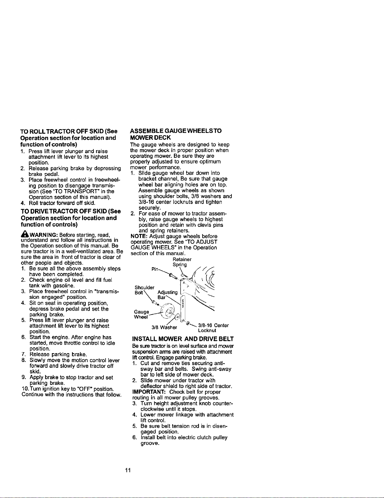
ASSEMBLE GAUGEWHEELSTO
MOWER DECK
The gauge wheels are designed to keep
the mower deck in proper position when
operating mower. Be sure they are
properly adjusted to ensure optimum
mower performance.
1. Slide gauge wheel bar down into
bracket channel, Be sure that gauge
wheel bar aligning holes are on top.
Assemble gauge wheels as shown
using shoulder bolts, 3/8 washers and
3/8-16 center Iocknuts and tighten
securely.
2. For ease of mower to tractor assem-
bly, raise gauge wheels to highest
position and retain with clevis pins
and spring retainers.
NOTE: Adjust gauge wheels before
operating mower. See "TO ADJUST
GAUGE WHEELS" in the Operation
section of this manual.
Retainer
Shoulder
Bolt\ Adjusting
Whee,
3/8 Was_he'r @_ 3/8 16 Center
Locknut
INSTALL MOWER AND DRIVE BELT
Be suretractorison level surfaceand mower
suspension armsare raisedwith attachment
liftcontrol.Engageparkingbrake.
1. Cut and remove ties securinganti-
sway bar and belts. Swing anti*sway
bar to left side of mower deck.
2. Slide mower under tractor with
deflector shield to rightside of tractor.
IMPORTANT: Check belt for proper
routing in all mower pulley grooves.
3. Turn height adjustment knob counter-
clockwise until it stops.
4. Lower mower linkage with attachment
lilt control
5. Be sure belt tension rod is in disen-
gaged position.
6. Install belt into electric clutch pulley
groove.
11
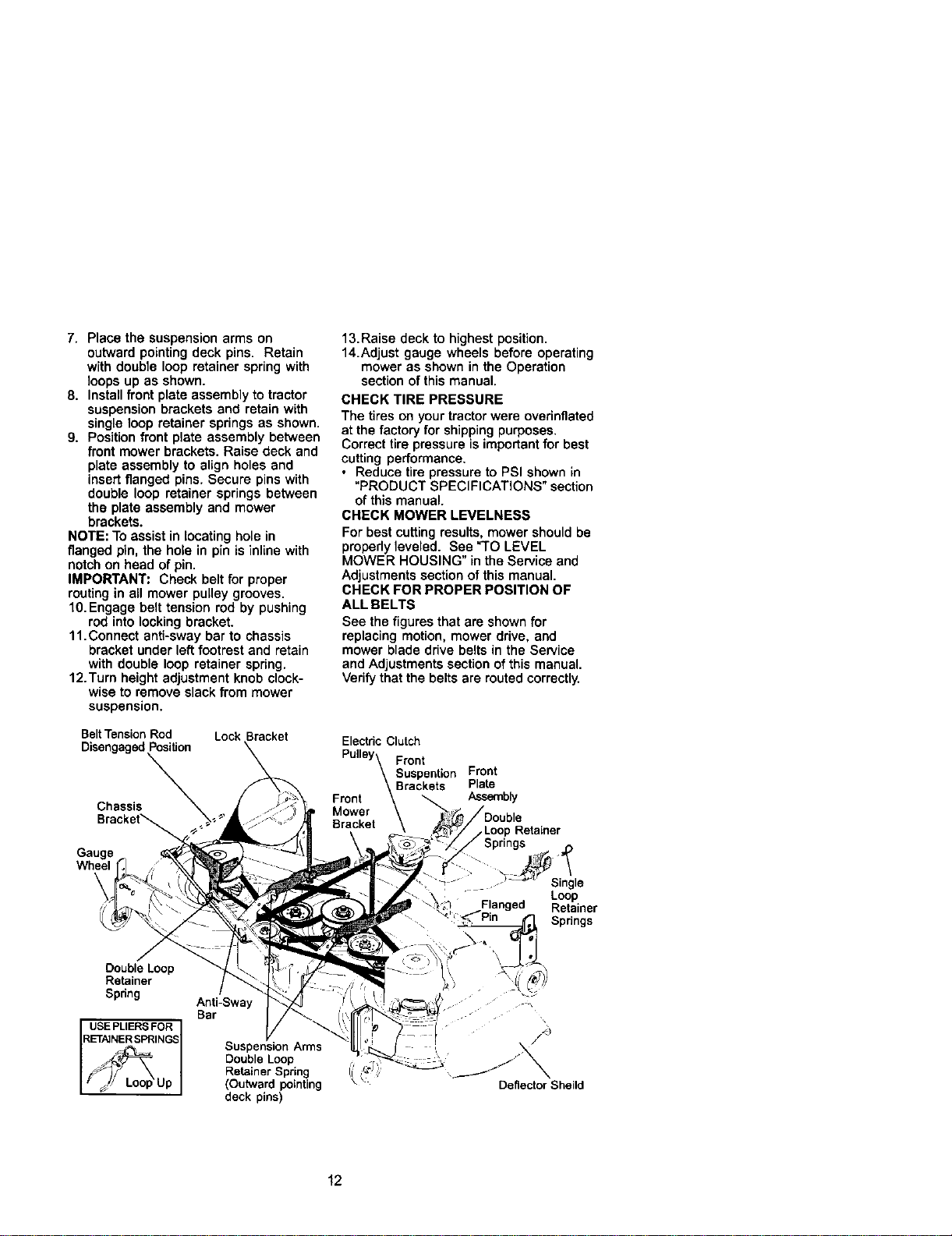
7. Place the suspension arms on
outward pointing deck pins. Retain
with double loop retainer spring with
loops up as shown.
8. Install front plate assembly to tractor
suspension brackets and retain with
single loop retainer springs as shown.
9. Position front plate assembly between
front mower brackets. Raise deck and
plate assembly to align holes and
insert flanged pins. Secure pins with
double loop retainer springs between
the plate assembly and mower
brackets.
NOTE: To assist in locating hole in
flanged pin, the hole in pin is inline with
notch on head of pin.
IMPORTANT: Check belt for proper
routing in all mower pulley grooves.
10. Engage belt tension rod by pushing
rod into locking bracket.
11.Connect anti-sway bar to chassis
bracket under left footrest and retain
with double loop retainer spring.
12.Turn height adjustment knob clock-
wise to remove slack from mower
suspension.
BeltTension Rod Lock Bracket
Disengaged Position
Chassis
Gauge
13.Raise deck to highest position.
14.Adjust gauge wheels before operating
mower as shown in the Operation
section of this manual.
CHECK TIRE PRESSURE
The tires on your tractor were overinflated
at the factoryfor shipping purposes.
Correcttire pressure isimportant for best
cutting performance.
• Reduce tire pressure to PSI shown in
"PRODUCT SPECIFICATIONS" section
of this manual.
CHECK MOWER LEVELNESS
For bestcutting results, mower should be
properly leveled. See "TO LEVEL
MOWER HOUSING" inthe Service and
Adjustments section of this manual.
CHECK FOR PROPER POSITION OF
ALL BELTS
See the figuresthat are shown for
replacing motion, mower drive, and
mower blade drive belts in the Service
and Adjustments section of this manual.
Verify that the belts are routed correctly.
Electdc Clutch
Pulley\ Front
\ Suspention Front
Front \Brackets PlateAssembly
Mower
Bracket\
.Loop Retainer
T Single
Loop
Flanged Retainer
Springs
Double Loop
Retainer
Spdng
USE PLIERS FOR
RT_NERSPRINGS//_Up
Anti-Sway
Bar
Suspension Arms
Double Loop
Retainer Spring
(Outward pointing
deck pins)
\
Deflector Sheild
12
,/'CHECKLIST
Before you operate and enjoy your new
tractor,we wish to assure that you receive
the best performance and satisfaction
from this Quality Product.
Please review the following checklist:
,/All assembly instructionshave been
completed.
,/'No remaining loose parts in carton.
,/'Battery is properly prepared and
charged. (Minimum 1 hour at 6 amps).
,/'Seat is adjusted comfortably and
tightened securely.
,/'All tires are properly inflated. (For
shipping purposes, the tires were
overinflated at the factory).
./Be sure mower deck is properly leveled
side-to-side/front-to-rear for best cutting
results. (Tires must be properly inflated
for leveling).
,/'Check mower and drive belts. Be sure
they are routed properly around pulleys
and inside all belt keepers.
,/Check wiring. See that all connections
are still secure and wires are properly
clamped.
,/Before drivingtractor, be sure free-
wheel control is in drive position.
While learning how to use your tractor,
pay extra attention to the following
important items:
,/" Engine oil is at proper level.
,/Fuel tank isfilled with fresh, clean,
regular unleaded gasoline.
,/Become familiar with all controls- their
location and function. Operate them
before you start the engine.
,/Be sure brake system is in safe
operating condition.
,/It is important to purge the transmission
before operating your tractor for the first
time. Follow proper starting and
transmission purging instructions(See
=TOSTART ENGINE" and "PURGE
TRANSMISSION" Lnthe Operation
section of this manual).
13
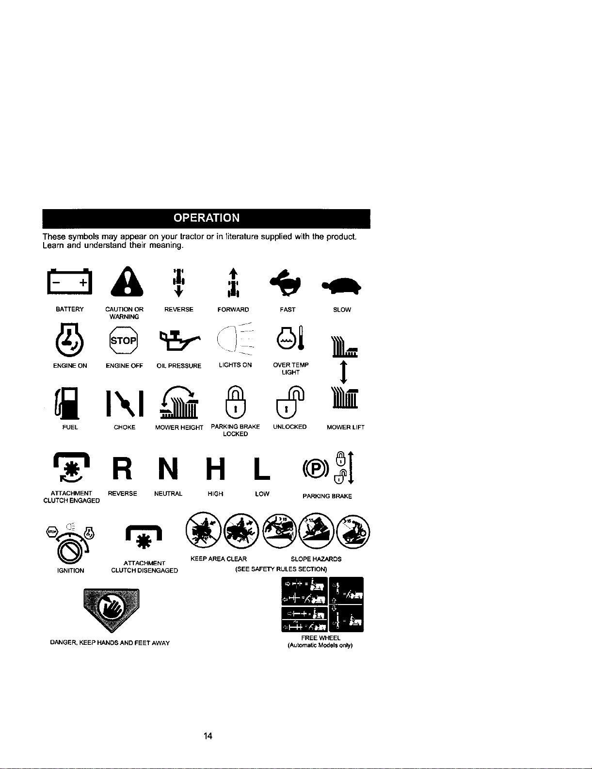
These symbols may appear onyour tractor or in literature suppliedwith the product.
Learn and understand their meaning,
BATTERY CAUTION OR REVERSE FORWARD FAST SLOW
WARNING
EHO,HEOHEHG,NEOF_O,LPRESSOREL,G.TSO.O%_MP 1
,IF
FUEL CHOKE MOWER HEIGHT PARKING BRAKE UNLOCKED MOWER LIFT
LOCKED
r_'l R N H L
ATrACHMENT REVERSE NEUTRAL HIGH LOW
CLUTCH ENGAGED
®3I
PARKING BRAKE
_(_ ATrACHMENT KEEP AREA CLEAR SLOPE HAZARDS
IGNITION CLUTCH DISENGAGED
OANGER, KEEP HANDS AND FEET AWAY
(SEE SAFETY RULES SECTION)
FREE WHEEL
(Automatic Modelsonly)
14
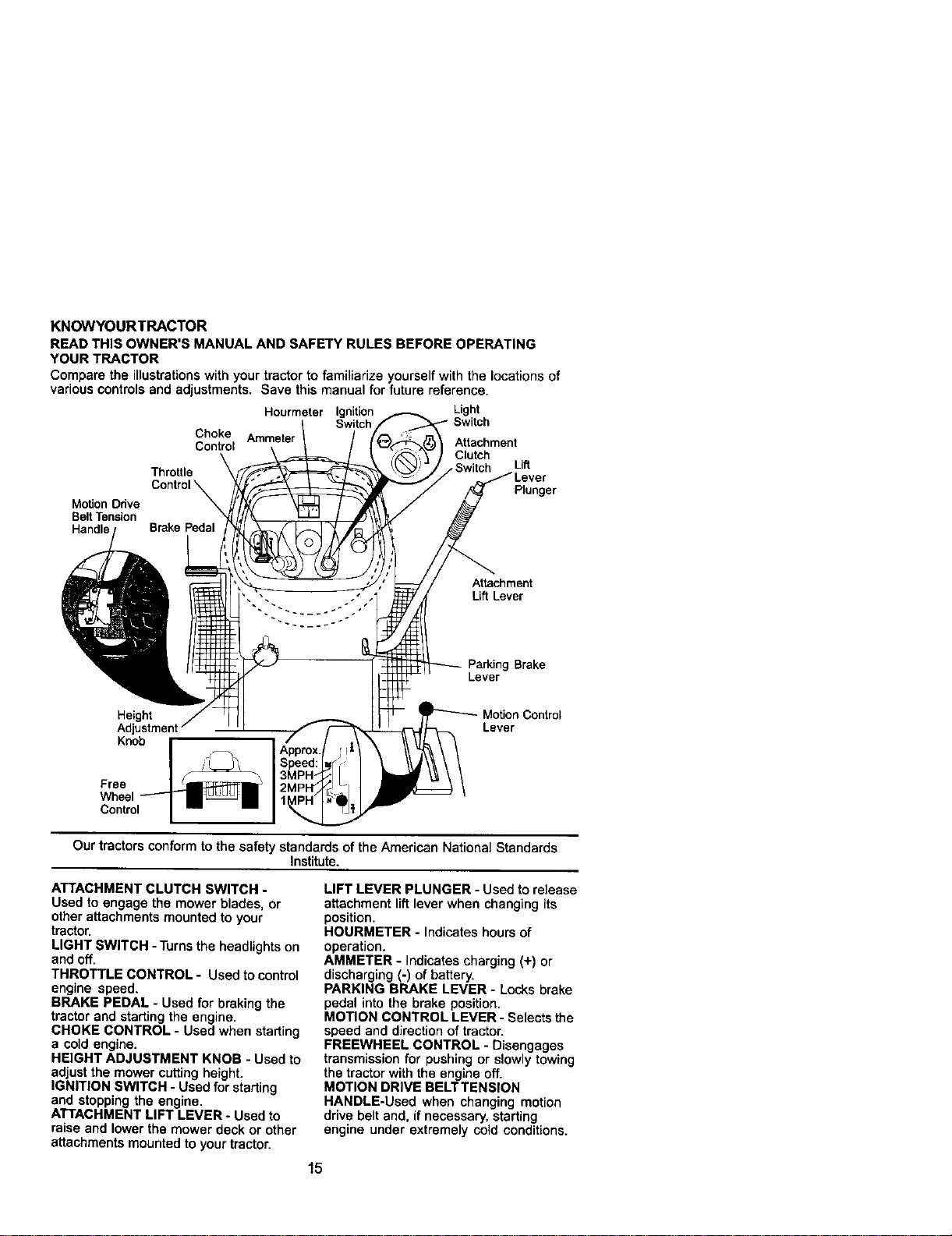
KNOWYOURTRACTOR
READ THIS OWNER'S MANUAL AND SAFETY RULES BEFORE OPERATING
YOUR TRACTOR
Compare the illustrations with your tractor to familiarize yourself with the locations of
various controls and adjustments. Save this manual for future reference.
Hourmeter Ignition Light
Switch Switch
Choke Attachment
Control Clutch
Lift
Throttle
Plunger
Motion Odve
Belt Tension
Handle
Attachment
Lift Lever
Parking Brake
Lever
Motion Control
Height Lever
Adjustment
Knob
Free
Wheel
Control
Our tractors conform tothe safety standards of the American National Standards
Institute.
ATTACHMENT CLUTCH SWITCH -
Used to engage the mower blades, or
other attachments mounted to your
tractor.
LIGHT SWITCH - Turns the headlights on
and off.
THROTTLE CONTROL - Used to control
engine speed.
BRAKE PEDAL - Used for braking the
tractor and starling the engine.
CHOKE CONTROL - Used when starting
a ooldengine.
HEIGHT ADJUSTMENT KNOB - Used to
adjust the mower cutting height.
IGNITION SWITCH - Used for starting
and stopping the engine.
ATTACHMENT LIFT LEVER - Used to
raise and lower the mower deck or other
attachments mounted to your tractor.
LIFT LEVER PLUNGER - Used to release
attachment lift lever when changing its
position.
HOURMETER - Indicates hours of
operation.
AMMETER - Indicates charging (+) or
discharging _-)of battery.
PARKING BRAKE LEVER - Locks brake
pedal into the brake position.
MOTION CONTROL LEVER - Selects the
speed and direction of tractor.
FREEWHEEL CONTROL - Disengages
transmission for pushing or slowly towing
the tractor with the engine off.
MOTION DRIVE BELTTENSION
HANDLE-Used when changing motion
drive belt and, if necessary, starting
engine under extremely cold conditions.
15
The operation of any tractor can result in foreign objects thrown into
the eyes, which can result in severe eye damage. Always wear safety
glasses or eye shields while operating your tractor or performing any
adjustments or repairs. We recommend a wide vision safety mask over
spectacles or standard safety glasses.
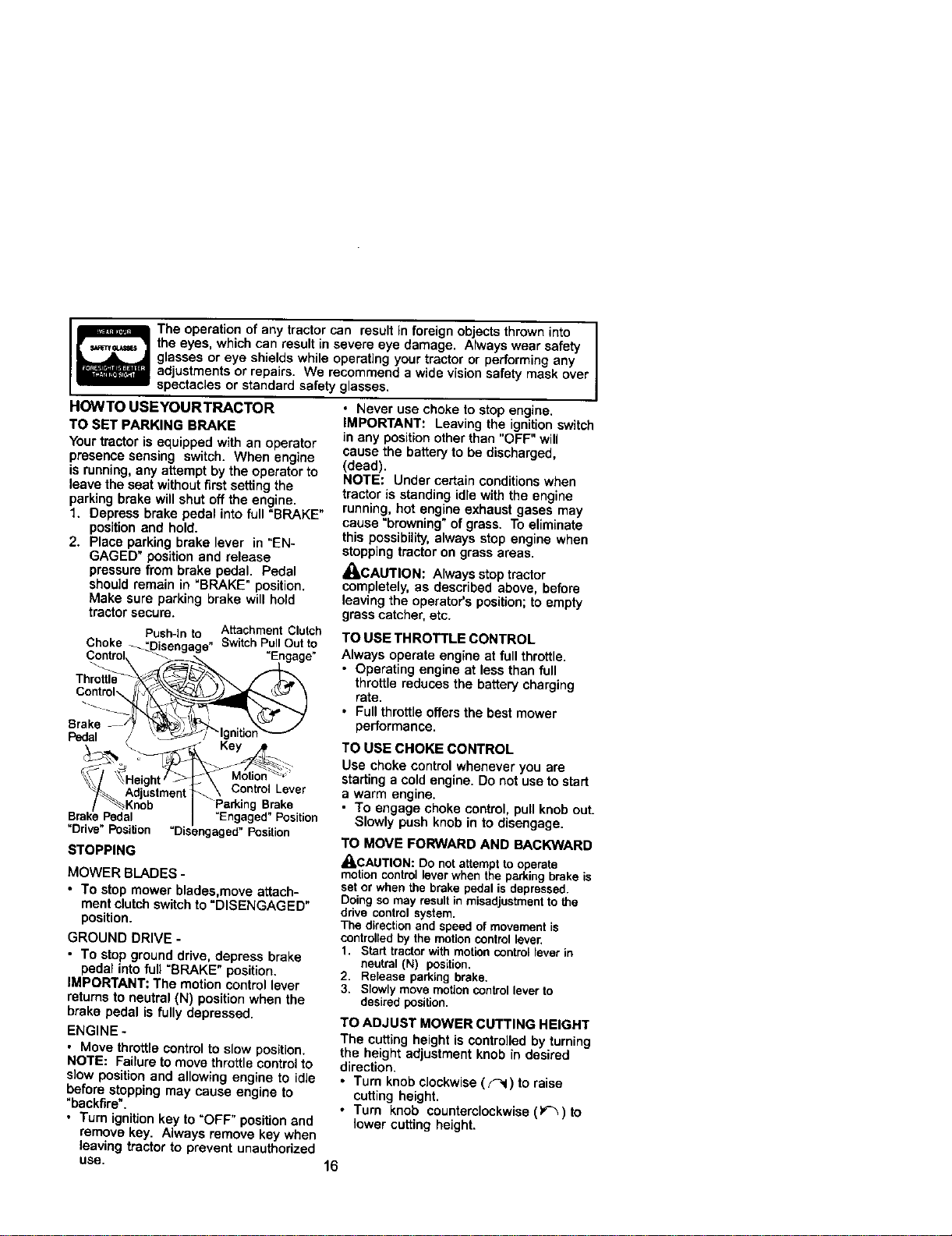
HOWTO USEYOURTRACTOR
TO SET PARKING BRAKE
Your tractor is equipped with an operator
presence sensing switch. When engine
is running, any attempt by the operator to
leave the seat without firstsetting the
parking brake will shut off the engine.
1. Depress brake pedal into full "BRAKE"
position and hold.
2. Place parking brake lever in "EN-
GAGED" position and release
pressure from brake pedal. Pedal
shou]dremain in "BRAKE" position.
Make sure parking brake will held
tractor secure.
Push-thto Attachment Clutch
Choke _ SwitchPullOutto
Brake
Psdal
Control Lever
Parking Brake
Pedal =Engaged" Position
"Drive" Position =Disengaged" Position
STOPPING
MOWER BLADES -
• To stop mower blades,move attach-
ment clutchswitch to "DISENGAGED"
position.
GROUND DRIVE -
• To stop ground drive, depress brake
pedal into full "BRAKE" position.
IMPORTANT: The motion control lever
returns to neutral (N) posit_onwhen the
brake pedal is fully depressed.
ENGINE -
• Move throttlecontrol to slow position.
NOTE: Failure to move throttle controlto
slow position and allowing engine to idle
before stopping may cause engine to
"backfire".
• Turn ignitionkey to "OFF" positionand
remove key. Always remove key when
leaving tractor to prevent unauthorized
use.
• Never use choke to stop engine.
IMPORTANT: Leaving the ignition switch
in any positionother than "OFF" will
cause the batteryto be discharged,
(dead).
NOTE: Under certain conditionswhen
tractor is standing idle with the engine
running, hot engine exhaust gases may
cause "browning" ofgrass. To eliminate
this possibility,always stop engine when
stopping tractor on grass areas.
_CAUTION: Always stoptractor
completely, as described above, before
leaving the operator's position;to empty
grass catcher, etc.
TO USE THROTTLE CONTROL
Always operate engine at full throttle.
• Operating engine at less than full
throttle reduces the battery charging
rate.
• Full throttleoffers the best mower
performance.
TO USE CHOKE CONTROL
Use choke control whenever you are
starting a cold engine, Do not use to start
a warm engine.
• To engage choke control, pull knob out.
Slowly push knob in to disengage.
TO MOVE FORWARD AND BACK3NARD
_CAUTION: Do not attempt to operate
motion control lever when the parking brake is
set or when the brake pedal is depressed.
Doing so may result in misadjustment to the
ddve control system.
The direction and speed of movement is
controlled by the motion control lever,
1. Start tractor with motion control lever in
neutral (N) position,
2. Release parking brake,
3. Slowly move motion control lever to
desired position.
TO ADJUST MOWER CUTTING HEIGHT
The cuttingheight is controlledby turning
the height adjustment knob in desired
direction.
• Turn knob clockwise (_) to raise
cutting height.
• Turn knob counterclockwise (_) to
lower cutting height.
16
The cutting height range is approximately
1-1/2" to 4-1/2". The heights are mea-
sured from the ground to the blade tip
with the engine not running.
These heights are approximate and may
vary depending upon soil conditions,
height of grass end types of grass being
mowed.
• The average lawn should be cut to
approximately 2-1/2 inches during the
cool season and to over 3 inches
during hot months. For healthier and
better looking lawns, mow often and
after moderate growth.
• For best cutting performance, grass
over 6 inches in height should be
mowed twice. Make the first cut
relatively high; the second to desired
height.
TO ADJUST GAUGE WHEELS
Gauge wheels are properly adjusted
when they are slightlyoff the ground
when mower is at the desired cutting
height in operating position. Gauge
wheels then keep the deck in proper
positionto help prevent scalping in most
terrain conditions.
NOTE: Be sure tractor is on a fiat level
surface.
1. Lower mower and adjust mower to
desired cutting height.
2. Remove retainer spring and clevis pin
which secure each gauge wheel bar.
3. Lower gauge wheels to ground. Raise
gauge wheels slightly to align holes in
bracket and gauge wheel bar and
insert clevis pin. Gauge wheels
should be slightly off the ground.
4. Replace retainer spring into clevis
pin.
IMPORTANT: Be sure to readjust gauge
wheels if you change the cutting height
of the mower deck.
Spdng
Clevis
Pin
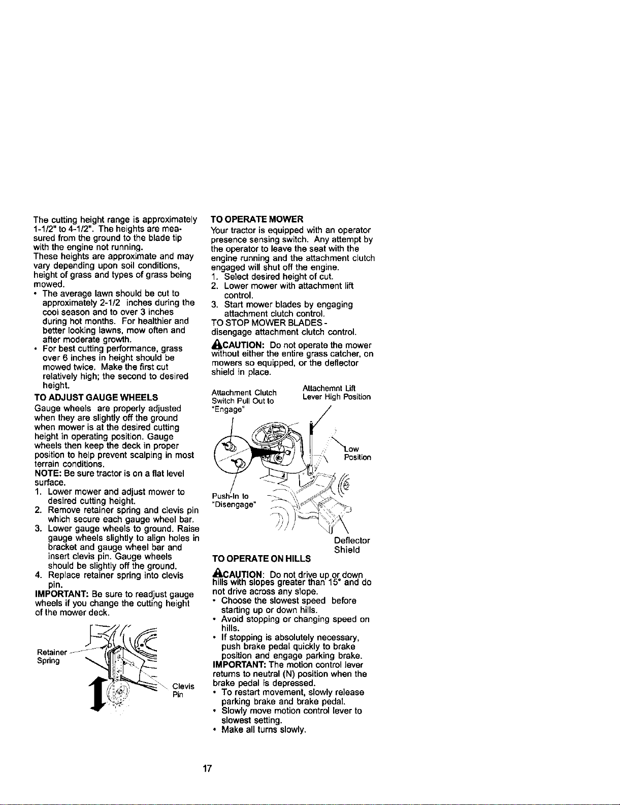
TO OPERATE MOWER
Your tractor is equipped with an operator
presence sensing switch. Any attempt by
the operator to leave the seat with the
engine running and the attachment clutch
engaged will shut offthe engine.
1. Select desired height of cut.
2. Lower mower with attachment lift
control.
3. Start mower blades by engaging
attachment clutchcontrol.
TO STOP MOWER BLADES -
disengage attachment clutchcontrol.
_LCAUTION: Do not operate the mower
withouteither the entire grass catcher, on
mowers so equipped, or the deflector
shield in place.
Attachment Clutch
Switch Pull Out to
"Engage"
Attachemnt Lift
Lever High Position
Position
Deflector
Shield
TO OPERATE ON HILLS
_,CAUTION: Do not drive up or down
hills with slopes greater than 15° and do
not drive across any slope.
• Choose the slowest speed before
starting up or down hills.
• Avoid stopping or changing speed on
hills.
• If stopping is absolutely necessary,
push brake pedal quickly to brake
position and engage parking brake.
IMPORTANT: The motion control lever
returns to neutral (N) position when the
brake pedal is depressed.
• To restart movement, slowly release
parking brake and brake pedal.
• Slowly move motion control lever to
slowest setting.
• Make all turns slowly.
17
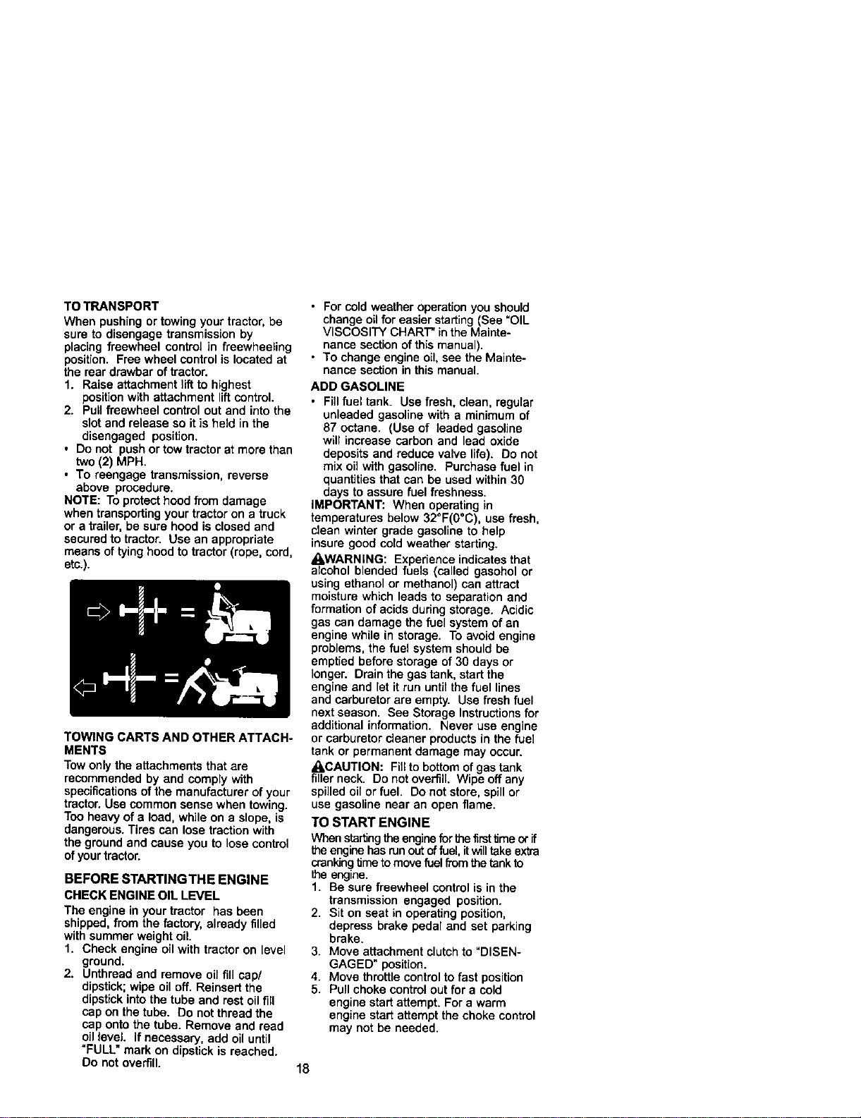
TO TRANSPORT
When pushing or towing your tractor,be
sure to disengage transmission by
placing freewheel control in freewheeling
position. Free wheel control is located at
the rear drawbar oftractor.
1. Raise attachment liftto highest
positionwith attachment liftcontrol.
2. Pull freewheel control out and into the
slot and release so it is held in the
disengaged position.
• Do not push or tow tractor at more than
two(2) MPH,
• To reengage transmission, reverse
above procedure,
NOTE: To protecthood from damage
when transportingyour tractor on a truck
or a trailer, be sure hood is closed and
secured to tractor. Use an appropriate
means of tying hood totractor (rope, cord,
etc.).
TOWING CARTS AND OTHER ATTACH-
MENTS
Tow onlythe attachments that are
recommended by and comply with
specifications of the manufacturer of your
tractor.Use common sense when towing.
Too heavy of a load, while on a slope, is
dangerous. Tires can lose traction with
the ground and cause you to lose control
of yourtractor.
BEFORE STARTINGTHE ENGINE
CHECK ENGINE OIL LEVEL
The engine in your tractor has been
shipped, from the factory, already filled
with summer weight oil.
1. Check engine oil with tractor on level
ground.
2. Unthread and remove oil fill cap/
dipstick;wipe oil off. Reinsert the
dipstick intothe tube and rest oil fill
cap on the tube. Do not thread the
cap onto the tube. Remove and read
oil level If necessary, add oil until
=FULL" mark on dipstick is reached.
Do not overfill.
• For cold weather operation you should
change oil for easier starting (See "OIL
VISCOSITY CHART" in the Mainte-
nance section of this manual).
• To change engine oil, see the Mainte-
nance section in this manual.
ADD GASOLINE
• Fillfuel tank. Use fresh, clean, regular
unleaded gasoline with a minimum of
87 octane, (Use of leaded gasoline
will increase carbon and lead oxide
deposits and reduce valve life). Do not
mix oil with gasoline. Purchase fuel in
quantitiesthat can be used within 30
days to assure fuel freshness.
IMPORTANT: When operating in
temperatures below 32°F(0°C), use fresh,
clean winter grade gasoline to help
insure good cold weather starting.
• LWARNING: Experience indicates that
alcohol blended fuels (called gasohol or
using ethanol or methanol) can attract
moisture which leads to separation and
formation of acids during storage. Acidic
gas can damage the fuel system of an
engine while in storage. To avoid engine
problems, the fuel system should be
emptied before storage of 30 days or
longer. Drain the gas tank, start the
engine and let it run until the fuel lines
and carburetor are empty. Use fresh fuel
next season. See Storage Instructions for
additional information. Never use engine
or carburetor cleaner products in the fuel
tank or permanent damage may occur.
_,CAUTION: Fillto bottom of gas tank
filler neck. Do not overfill. Wipe off any
spilled oil or fuel. Do not store, spill or
use gasoline near an open flame.
TO START ENGINE
When startingthe engine for _e firsttime ot if
the engine has run out of fuel, it will take extra
cranking Umeto movefuel from the tankto
the engine.
1. Be sure freewheel control is in the
transmission engaged position.
2. Sit on seat in operating position,
depress brake pedal and set parking
brake.
3. Move attachment clutch to "DISEN-
GAGED" position.
4. Move throttle control to fast position
5. Pull choke control out for a cold
engine start attempt. For a warm
engine start attempt the choke control
may not be needed.
18

NOTE: Before staring, read the warm and
cold starting procadur_s below.
6. Insert key into ignitionand turn key
clockwise to "START" position and
release key as soon as engine starts.
Do not run starter continuously for
more than fifteen seconds per minute.
If the engine does not start after
several attempts, push choke control
in, wait a few minutes and try again. If
engine still does not start, pull the
choke control out and retry.
WARMWEATHER STARTING (50° Fand
above)
7. When engine starts, slowly push
choke control in until the engine
begins to run smoothly. If the engine
starts to run roughly, pull the choke
control out slightly for a few seconds
and then continue to push the control
in slowly.
• The attachments and ground ddve can
now be used.Ifthe engine does not accept
the load, restartthe engine and a]k)witto
warm up for one minute using the choke
as described above.
COLD WEATHER STARTING (50° F and
below)
7. When engine starts, slowly push
choke control in until the engine
begins to run smoothly. Continue to
push the choke control in small steps
allowing the engine to accept small
changes in speed and load, until the
choke control is fully in. If the engine
starts to run roughly, pull the choke
control out slightly for a few seconds
and then continue to push the control
in slowly. This may require an engine
warm-up period from several seconds
to several minutes, depending on the
temperature.
NOTE: In extreme cold conditions, if
engine will not start you may need to
disengage the motion drive belt as
follows:
1. Be sure parking brake is engaged.
2. Remove retainer spring from the drive
belt tension handle to relieve belt
tension.
3. Start engine and allow it to warm up
for three (3) minutes.
4. Shut-off engine and engage parking
brake.
5. Engage drive belt tension handle and
replace the retainer spring.
AUTOMATICTRANSMISSION WARM UP
Before driving the unit in cold weather,
the transmission should be warmed up as
follows:
1. Be sure the tractor is on level ground.
2. Place the motion control lever in
neutral. Release the parking brake
and let the brake slowly return to
operating position.
3. Allow one minute for transmission to
warm up. This can be done during the
engine warm up period.
• The attachments can be used during
the engine warm-up period after the
transmission has been warmed up and
may require the choke control be
pulled out slightly.
NOTE: If at a high altitude (above 3000
feet) or in cold temperatures (below 32 F)
the carburetor fuel mixture may need to
be adjusted for best engine performance.
See "TO ADJUST CARBURETOR" in the
Service and Adjustments section of this
manual.
PURGETRANSMISSION
_CAUTION: Never engage or disen-
gage freewheel lever while the engine is
running.
To ensure proper operation and perfor-
mance, itis recommendedthat the
transmissionbe purged before operating
tractorforthe first time.This procedurewill
removeany trapped air inside the trans-
mission which may have developed during
shippingofyour tractor.
IMPORTANT: Should your transmission
require removal for serviceor replacement,
it should be purged after reinstallation
beforeoperating the tractor.
1. Place tractor safely on level surface
with engine off and parking brake set.
2. Disengage transmission by placing
freewheel control in freewheeling
position(See "TO TRANSPORT" in
this section of manual).
3. Sittingin the tractor seat, start engine.
After the engine is running, move
throttlecontrol to slow position.
Disengage parking brake.
4. Move motioncontrol lever to full
forward positionand hold for five (5)
seconds. Move lever to full reverse
position and hold for five (5) seconds.
Repeat this procedure three (3) times.
NOTE: Duringthis procedurethere will be
no movementof drivewheels. The air is
being removed from hydraulicdrive
system.
19
5. Move motion control lever to neutral
(N) position. Shut- off engine and set
parking brake.
6. Engage transmission by placing
freewheel control in driving position
(See "TO TRANSPORT" in this section
of manual).
7. Sitting in the tractor seat, start engine.
After the engine is running, move
throttle control to half (1/2) speed.
Disengage parking brake.
8. Slowly move motion control lever
forward, after the tractor moves
approximately five (5) feet, slowly
move motion control lever to reverse
position. After the tractor moves
approximately five (5) feet return the
motion control lever to the neutral (N)
position. Repeat this procedure with
the motion control lever three (3)
times.
Your tractor is now purged and now ready
for normal operation.
MOWlNGTIPS
• Tire chains cannot be used when the
mower housing is attached to tractor.
• Mower should be propedy leveled for
best mowing performance. See "TO
LEVEL MOWER HOUSING" in the
Service and Adjustments section of this
manual.
• The left hand side of mower should be
used for trimming.
• Drive so that clippings are discharged
onto the area that has been cut. Have
the cut area tothe rightof the tractor.
This will result in e more even distribu-
tion of clippings and more uniform
cutting.
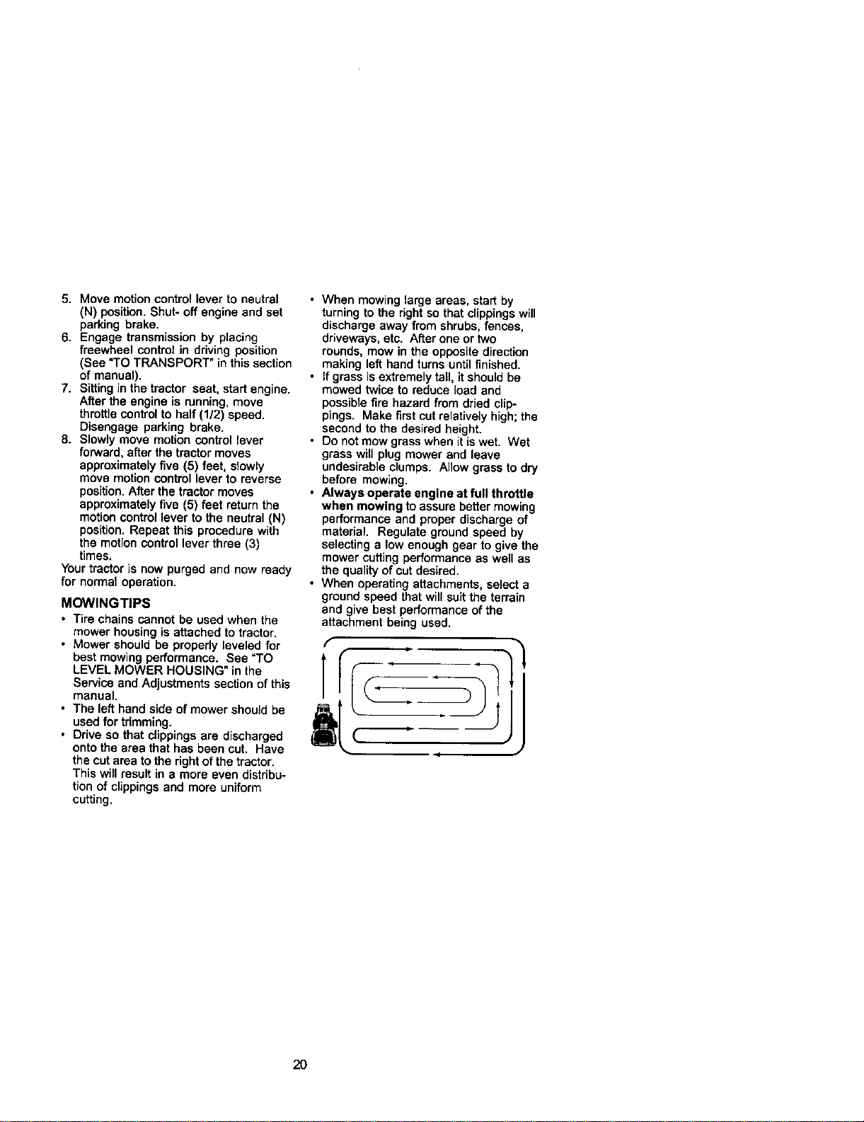
• When mowing large areas, start by
turning to the right so that clippingswill
discharge away from shrubs, fences,
driveways, etc. After one or two
rounds, mow in the opposite direction
making left hand turns until finished.
• If grass is extremely tall, it should be
mowed twice to reduce load and
possible fire hazard from dried clip-
pings. Make first cut relatively high; the
second to the desired height.
• Do not mow grass when it is wet. Wet
grass will plug mower and leave
undesirable clumps. Allow grass to dry
before mowing.
• Always operate engine at full throttle
when mowing to assure better mowing
performance and proper discharge of
material. Regulate ground speed by
selecting a low enough gear to give the
mower cutting performance as well as
the quality of cut desired.
• When operating attachments, select a
ground speed that will suit the terrain
and give best performance of the
attachment being used.
f
• 1
2O
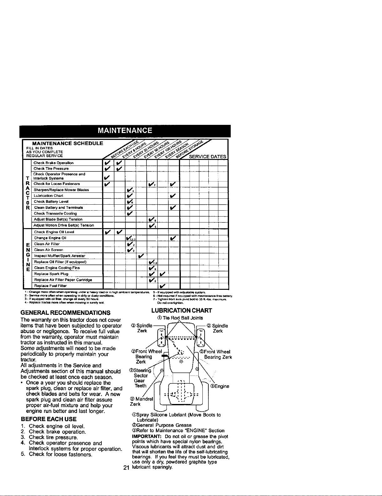
MAINTENANCE SCHEDULE
FILL IN DATES
ASYOU COMPLETE
REGULAR SERVICE
T
R
A
C
T
0
R
E
N
G
I
N
E
Check Brake Operation
Check Tire Pressure
Check Operator Plesence and
Interlock Systems
Check for Loose Fasteners
Sharpen/Replace Mower Blades
Lubrication Chart
Check Battery Level
Clean Battery and Terminals
Check Traz=sexle Cooling
Adjust Blade Belt(s) Tension
Adjust Motion Ddve Belt(s) Tension
Check Engine Oil Level
Change Engine Oil
C_ean Air FUter
Clean Air Sc:reen
Inspsct Muffler/Spark Arrester
Replace Oil Filter (If equipped)
Clean Engine Cooling Fins
Replace Spark Plug
Replace Air Filter Paper Cartridge
Replace Fuel Filter
1 - Ch,_ mo_e o_n wt_fl o_QJng urtd_ a helJW IOBd Or in h_gh arftbieP__. 5. if equipped _th adjl_l_b_ system
2. _ r_x_e 0Itemwhen q:p_raung in _ny c*-dUSly o_d_t k_ 6 * No( req_,_d if equLpped _th maint_a_-ftms bat;ery.
3. If equipped _m o_ fllmr, =_ar_Q _1 _ 50 houri 7. _ghten f_t ixl_ pl,,_t _(_t *o 35 rt .ibs rr_xbmum
4. R_ _Je= mona _ w_en mc_ng in ur,_y _1 [3o r_t o_ml_en
GENERAL RECOMMENDATIONS
The warranty onthis tractordoes not cover
items that have been subjected to operator
abuse or negligence. To receive full value
from the warranty,operator must maintain
tractor as instructedin thismanual.
Some adjustmentswill need to be made
pedodicallyto properly maintainyour
tractor.
All adjustmentsin the Service and
Adjustments sectionof this manual should
be checked at least onceeach season.
• Once a year you should replace the
spark plug,clean or replace airfilter, and
check blades and beltsfor wear. A new
spark plugand clean air filter assure
proper air-fuelmixture and help your
engine run better and last longer.
BEFORE EACH USE
1. Check engine oil level.
2. Check brake operation.
3. Check tire pressure.
4. Check operator presence and
interlock systems for proper operation.
5. Check for loose fasteners.
LUBRICATION CHART
(_Tie RodBallJoints
Zerk _ Zerk
_Front Wheel r- _#;.: X
Beadng _ _-.-----.-.- _ BearingZerk
Zerk _ _ '.,_ , -
.-/
_Steedng ):'_;_
Sector /-1
Gear _-J
_Mandrel I - ".......
Zerk _ _'
.J
_Spray SiliconeLubdant(MoveBootsto
Lubdcate)
_General PurposeGrease
@Referto Maintenance=ENGINE"Section
IMPORTANT: Do notoilor greasethepivot
pointswhichhave specialnylonbearings.
Viscouslubricantswillattractdustanddirt
thatwillshortenthelifeofthe self-lubricating
beadngs. Ifyoufeel theymustbelubricated,
useonlya dry,powderedgraphitetype
21 lubricant sparingly.
TRACTOR
Always observe safety rules when
performing any maintenance.
BRAKE OPERATION
Iftrector requires more than six (6) feet
stopping distance at high speed in
highest gear, then brake must be ad-
justed. (See "TO ADJUST BRAKE" in the
Service and Adjustments section of this
manual).
TIRES
• Maintain proper air pressure in all tires
(See "PRODUCT SPECIFICATIONS"
section of this manual).
• Keep tires free of gasoline, oil, or insect
control chemicals which can harm
rubber.
• Avoid stumps, stones, deep ruts, sharp
objects and other hazards that may
cause tire damage.
NOTE: To seal tire punctures and prevent
flat tires due to slow leaks, tire sealant
may be purchased from your local parts
dealer. Tire sealant also prevents tire dry
"rot and corrosion.
OPERATOR PRESENCE SYSTEM
Be sure operator presence and interlock
systems are working properly, if your
tractor does not function as described,
repair the problem immediately.
• The engine should not start unless the
brake pedal is fully depressed and
attachment clutchcontrol is in the
disengaged position.
• When the engine is running, any
attempt by the operator to leave the
seat without first setting the parking
brake should shut off the engine.
• When the engine is running and the
attachment clutch is engaged, any
attempt by the operator to reave the
seat should shut off the engine.
• The attachment clutch should never
operate unless the operator is in the
seat.
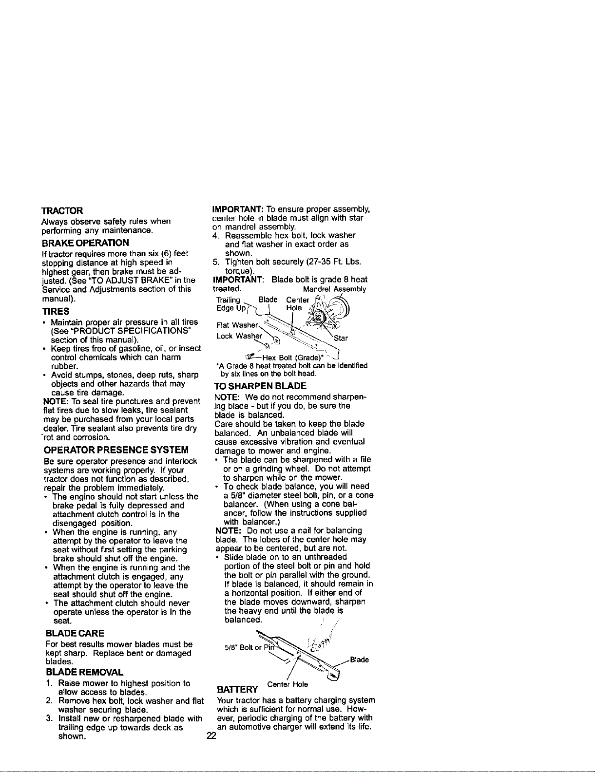
IMPORTANT: To ensure proper assembly,
center hole in blade must alignwith star
on mandrel assembly.
4. Reassemble hex bolt, lock washer
and fiat washer in exact order as
shown.
5, Tighten boltsecurely (27-35 Ft. Lbs.
torque).
IMPORTANT: Blade bolt is grade 8 heat
treated. MandrelAssembly
Blade Center
Hole
FlatWasher
Lock
_--Hex Bolt(Grade)
*A Grade8 heattreatedboltcanbe identified
by sixlinesonthe bolthead.
TO SHARPEN BLADE
NOTE: We do not recommend sharpen-
ing blade - but if you do, be sure the
blade is balanced.
Care should be taken to keep the blade
balanced. An unbalanced blade will
cause excessive vibration and eventual
damage to mower and engine.
• The blade can be sharpened with a file
or on a grindingwheel. Do not attempt
to sharpen while on the mower.
• To check blade balance, you will need
a 5/8" diameter steel bolt, pin, or a cone
balancer, (When using a cone bal-
ancer, follow the instructionssupplied
with balancer,)
NOTE: Do not use a nail for balancing
blade. The lobes ofthe center hole may
appear to be centered, but are not.
• Slide blade on to an unthreaded
portionof the steel bolt or pin and hold
the bolt or pin parallel with the ground,
If blade is balanced, it should remain in
a horizontal position. If either end of
the blade moves downward, sharpen
the heavy end until the blade is
balanced.
BLADE CARE
For best results mower blades must be
keptsharp. Replace bent or damaged
blades.
BLADE REMOVAL
1. Raise mower to highest positionto
allow access to blades,
2. Remove hex bolt, lock washer and fiat
washer securing blade.
3. Install new or resharpened blade with
trailing edge up towards deck as
shown.
CenterHole
BATTERY
Your tractor has a battery charging system
which is sufficient for normal use. How-
ever, periodic charging of the battery with
an automotive charger will extend its life.
22
• Keep battery and terminals clean.
• Keep battery bolts tight.
• Keep small vent holes open.
• Recharge at 6-10 amperes for 1 hour.
NOTE: The original equipment battery on
your tractor ismaintenance free. Do not
attempt to open or remove caps or covers.
Adding or checking level of electrolyte is
not necessary.
TO CLEAN BATTERY AND TERMINALS
Corrosion and dirt on the battery and
terminals can cause the batteryto "leak"
power.
1. Remove terminal guard.
2. Disconnect BLACK battery cable first
then RED battery cable and remove
batteryfrom tractor.
3. Rinse the battery with plain water and
dry.
4. Clean terminals and battery cable
ends with wire brush until bright.
5. Coat terminals with grease or petro-
leum jelly.
6. Reinstall battery (See "REPLACING
BATTERY" in the SERVICE AND
ADJUSTMENTS section ofthis
manual).
V-BELTS
Check V-belts for deterioration and wear
after 100 hours of operation and replace
if necessary. The belts are notadjustable.
Replace belts if they begin to slip from
wear.
TRANSAXLE COOLING
The transmissionfan and cooling fins
should be kept clean to assure proper
cooling.
Do notattempt to clean fan or transmis-
sion while engine is runningor while the
transmission is hot.To prevent possible
damage to seals, do not use high
pressurewater or steam to clean
transaxle.
• Inspect coolingfan to be sure fan
blades are intact and clean.
• inspect coolingfins for dirt, grass
clippings and other materials. To
prevent damage to seals, do notuse
compressed air or high pressure
sprayer to clean coolingfins.
TRANSAXLE PUMP FLUID
The transaxle was sealed at the factory
and fluid maintenance is not required for
the life ofthe transaxle. Should the
transaxle ever leak or require servicing,
contact your nearest authorized service
centeddepartment.
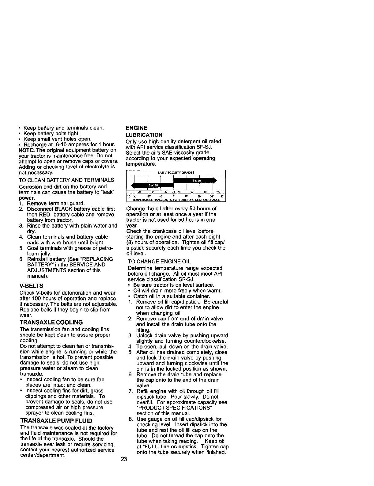
ENGINE
LUBRICATION
Only use high quality detergent oil rated
withAPI service classificationSF-SJ.
Select the oil's SAE viscosity grade
according to your expected operating
temperature.
I .... " "
TEM_=RATURE RANGE AI_ICIPATE D _EFORE NEXT C4L C_NGE
Change the oil after every 50 hours of
operationor at least once a year if the
tractor is not used for 50 hours in one
year.
Check the crankcase oil level before
starting the engine and after each eight
(8) hours ofoperation. Tighten oil fill cap/
dipstick securely each time you check the
oil level.
TO CHANGE ENGINE OIL
Determine temperature range expected
before oil change. All oil must meet API
service classification SF-SJ.
• Be sure tractor is on level surface.
• Oil will drain more freely when warm.
• Catch oil in a suitable container.
1. Remove oil fill cep/dipstick. Be careful
not to allow dirt to enter the engine
when changing oil,
2. Remove cap from end of drain valve
and install the drain tube onto the
fitting.
3. Unlock drain valve by pushing upward
slightly and turning counterclockwise.
4. To open, pull down on the drain valve.
5. After oil has drained completely, close
and lock the drain valve by pushing
upward and turning clockwise until the
pin is in the locked position as shown.
6. Remove the drain tube and replace
the cap onto to the end of the drain
valve.
7. Refill engine with oil through oil fill
dipstick tube. Pour slowly. Do not
overfill. For approximate capacity see
"PRODUCT SPECIFICATIONS"
section of this manual.
8. Use gauge on oil fill cap/dipstick for
checking level. Insert dipstick into the
tube and rest the oil fill cap on the
tube. Do not thread the cap onto the
tube when taking reading. Keep oil
at "FULL" line on dipstick. Tighten cap
onto the tube securely when finished.
23
Oil DrainValve
Draiia_be_Closed and
CLEAN AIR SCREEN Locked Position
Air screen must be kept free of dirtand
chaff to prevent engine damage from
overheating. Clean with a wire brush or
compressed air to remove dirt and
stubborndried gum fibers.
CLEAN AIR INTAKE/COOLING AREAS
To insure proper cooling, make sure the
grass screen, cooling fins, and other
external surfaces of the engine are kept
clean at all times.
Every 100 hours of operation (more often
under extremely dusty, dirty conditions),
remove the blower housing and other
coolingshrouds. Clean the cooling fins
and external surfaces as necessary. Make
sure the cooling shrouds are reinstalled.
NOTE: Operating the engine with a
blocked grass screen, dirty or plugged
cooling fins, and/or cooling shrouds
removed will cause engine damage due
to overheating.
AIR FILTER
Your engine will not run properly using a
dirty air filter. Clean the foam pre-oleaner
after every 25 hours of operation or every
season. Service paper cartridge every
100 hours of operation or every season,
whichever occurs first.
Service air cleaner more often under
dusty conditions.
1. Loosen knob and remove cover.
TO SERVICE PRE-CLEANER
2. Slide foam pre-cleaner off cartridge.
3. Wash it in liquid detergent and water.
4. Squeeze it dry in a clean cloth. Allow
itto dry.
5. Saturate itin engine oil. Wrap itin
clean, absorbent cloth and squeeze to
remove excess oil.
TO SERVICE CARTRIDGE
• Replace a dirty,bent, or damaged
cartridge.
NOTE: Do not wash the paper cartridge
or use pressurized air, as this will
damage the cartridge.
6. Remove nut and cartddge plate.
7. Reinstall the pre-cleaner (cleaned
and oiled) over the paper cartridge.
8. Check rubber seal for damage and
proper position around stud. Replace
if necessary.
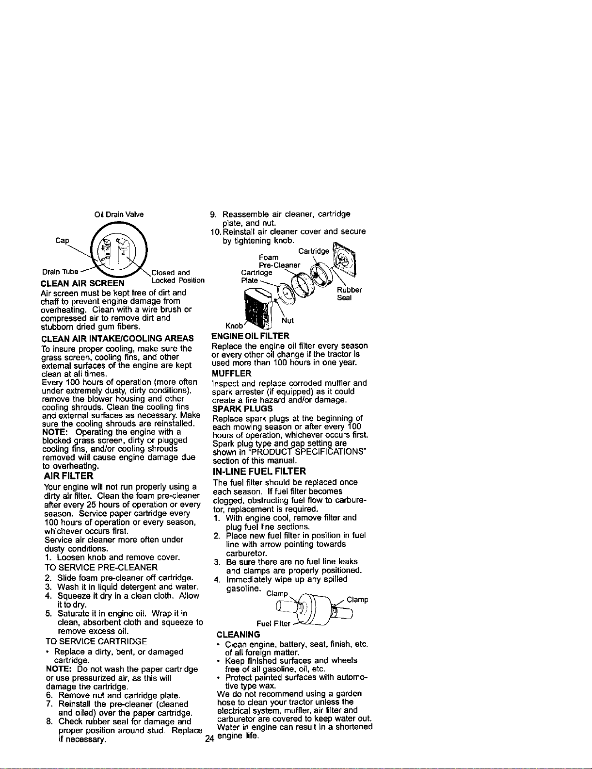
9. Reassemble air cleaner, cartridge
plate, and nut.
10. Reinstall air cleaner cover and secure
by tightening knob.
Cartridge
Foam
Pre-Cleaner
Cartridge
Rubber
Seal
Nut
ENGINE OIL FILTER
Replace the en_)ine oilfilter every season
or every other odchange if the tractor is
used more than fO0 hours in one year.
MUFFLER
Inspect and replace corroded muffler and
spark arrester (if equipped) as it could
create a fire hazard and/or damage.
SPARK PLUGS
Replace spark plugs at the beginning of
each mowing season or after every 100
hours of operation, whichever occurs first.
Spark plug type and gap setting are
shown in "PRODUCT SPECIFICATIONS"
section of this manual.
IN-LINE FUEL FILTER
The fuel filtershould be replaced once
each season. If fuel filter becomes
clogged, obstructingfuel flow to carbure-
tor, replacement is required.
1. With engine cool, remove filter and
plug fuel line sections.
2. Place new fuel filter in position in fuel
line with arrow pointingtowards
carburetor.
3. Be sure there are no fuel line leaks
and clamps are properly positioned.
4. Immediately wipe up any spilled
gasoline. Clamp.
(l
FuelFilter
CLEANING
• Clean engine, battery, seat, finish, etc.
ofall foreign matter.
• Keep finished surfaces and wheels
free of all gasoline, oil, etc.
• Protect painted surfaces with automo-
tive type wax.
We do not recommend using a garden
hose to clean your tractor unless the
electrical system, muffler, airfilter and
carburetor are covered to keep water out.
Water in engine can result in a shortened
24 engine life.
,_CAUTION: BEFORE PERFORMING ANY SERVICE OR ADJUSTMENTS:
1. Depress brake pedal fullyand set parking brake.
2. Place attachment clutch in "DISENGAGED" position.
3. Turn ignitionkey =OFF" and remove key.
4. Make sure the blades and all moving parts have completely stopped.
5. Disconnect spark plug wire from spark plug and place wire where it cannot
come in contact with plug.
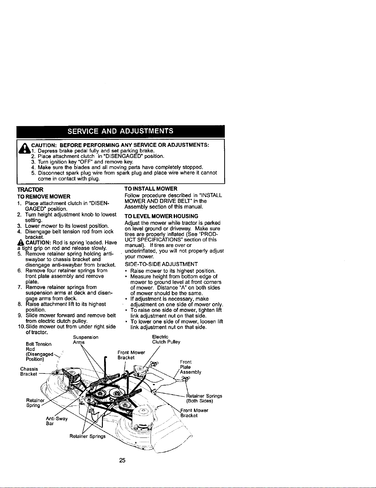
TRACTOR
TO REMOVE MOWER
1. Place attachment clutchin "DISEN-
GAGED" position.
2. Turn height adjustment knob to lowest
setting.
3. Lower mower to its lowest position.
4. Disengage belt tension rod from lock
bracket.
CAUTION: Rod is springloaded. Have
a tight grip on rod and release slowly.
5. Remove retainer spring holding anti-
swaybar to chassis bracket and
disengage anti-swaybar from bracket.
6. Remove four retainer springsfrom
front plate assembly and remove
plate.
7. Remove retainer springsfrom
suspension arms at deck and disen-
gage arms from deck.
8. Raise attachment liftto its highest
position.
9. Slide mower forward and remove belt
from electric clutch pulley.
lO.Slide mower outfrom under right side
oftractor.
Suspension
BeltTension
Rod
(Disengaged,_'
Position)
,,,
Chassis
TO INSTALL MOWER
Follow procedure described in =INSTALL
MOWER AND DRIVE BELT"in the
Assembly section of this manual.
TO LEVEL MOWER HOUSING
Adjust the mower while tractor is parked
on level ground or driveway. Make sure
tires are properly inflated (See "PROD-
UCT SPECIFICATIONS" section ofthis
manual). If tires are over or
underinflated, you will not propedy adjust
your mower.
SIDE-TO-SIDE ADJUSTMENT
• Raise mower to its highest position.
• Measure height from bottom edge of
mower to ground level at front corners
of mower. Distance "A" on both sides
of mower should be the same.
• If adjustment is necessary, make
adjustment on one side of mower only.
• To raise one side of mower, tighten lift
link adjustment nut on that side.
• To lower one side of mower, loosen lift
link adjustment nut on that side.
Electric
Clutch Pulley
Front Mower
Bracket
Front
=late
Retainer
Spdn
Anti-Sway
Bar
pdngs
(Both Sides)
, Bracket
/
25
NOTE: Each full turn of adjustment nut
will change mower height about 3/16".
• Recheck measurements after adjust-
ing.
BottomEdgeof BottomEdgeof
MowertoGround Mowerto Ground
AI GROUND' - TA
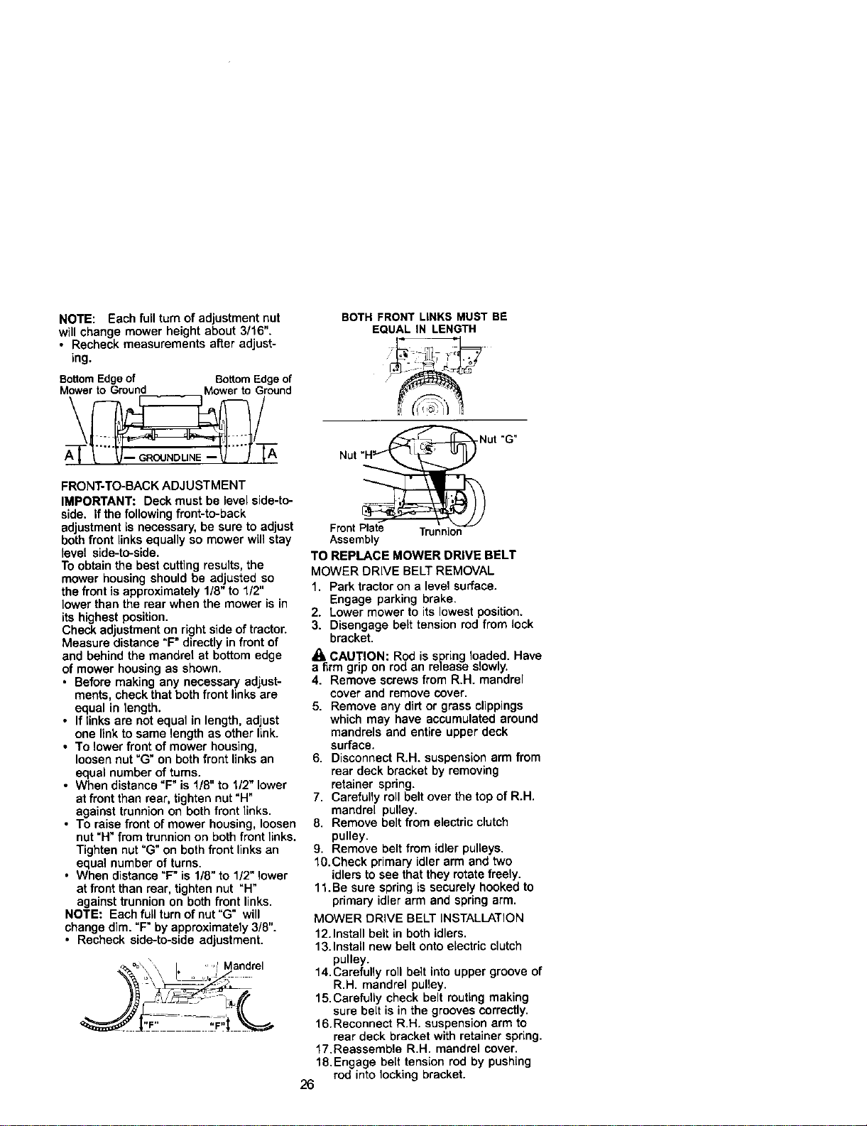
FRONT-TO-BACK ADJUSTMENT
IMPORTANT: Deck must be level side-to-
side. if the following front-to-back
adjustment is necessary, be sure to adjust
both front linksequally so mower will stay
level side-to-side.
Toobtain the bestcutting results, the
mower housing should be adjusted so
the frontis approximately 1/8"to 1/2"
lower than the rear when the mower is in
its highest position.
Check adjustment on right side of tractor.
Measure distance "F" directly in front of
and behind the mandrel at bottom edge
of mower housing as shown.
• Before making any necessary adjust-
ments, check that both front linksare
equal in length.
• If links are notequal in length, adjust
one linkto same length as other link.
• To lower front of mower housing,
loosen nut "G" on both front links an
equal number of tums.
• When distance "F" is 1/8" to 1/2" lower
at front than rear, tighten nut "H"
against trunnion on both front links.
• To raise front of mower housing, loosen
nut"H"from trunnion on both front links.
Tighten nut=G"on both front linksan
equal number of turns.
• When distance=F" is 1/8" to 1/2" lower
at front than rear, tighten nut "H"
against trunnion on both front links.
NOTE: Each full turnof nut"G" will
change dim. "F"by approximately 3/8".
• Recheck side-to-side adjustment.
\
_x\ \\ I * 'l' Mandrel
BOTH FRONT LINKS MUST BE
EQUAL IN LENGTH
Nut "G"
Front Plate Trunnion
Assembly
TO REPLACE MOWER DRIVE BELT
MOWER DRIVE BELT REMOVAL
1. Park tractor on a level surface.
Engage parking brake.
2. Lower mower to its lowest position.
3. Disengage belt tension rod from lock
bracket.
_l, CAUTION: Rod is spring loaded. Have
a firm grip on rod an remase slowly.
4. Remove screws from R.H. mandrel
cover and remove cover.
5. Remove any dirt or grass clippings
which may have accumulated around
mandrels and entire upper deck
surface.
6, Disconnect R.H. suspension arm from
rear deck bracket by removing
retainer spring.
7, Carefully roll belt over the top of R.H.
mandrel pulley.
8. Remove belt from electric clutch
pulley.
9, Remove belt from idler pulleys,
1O,Check primary idler arm and two
idlers to see that they rotate freely.
11.Be sure spring is securely hooked to
primary idler arm and spring arm,
MOWER DRIVE BELT INSTALLATION
12.Install belt in both idlers,
13.Install new belt onto electric clutch
pulley.
14,Carefully roll belt into upper groove of
R,H, mandrel pulley,
15,Carefully cheek belt routingmaking
sure belt is in the grooves correctly,
16.Reconnect R.H. suspension arm to
rear deck bracket with retainer spring.
17.Reassemble R,H. mandrel cover,
18. Engage belt tension rod by pushing
rod into locking bracket.
26
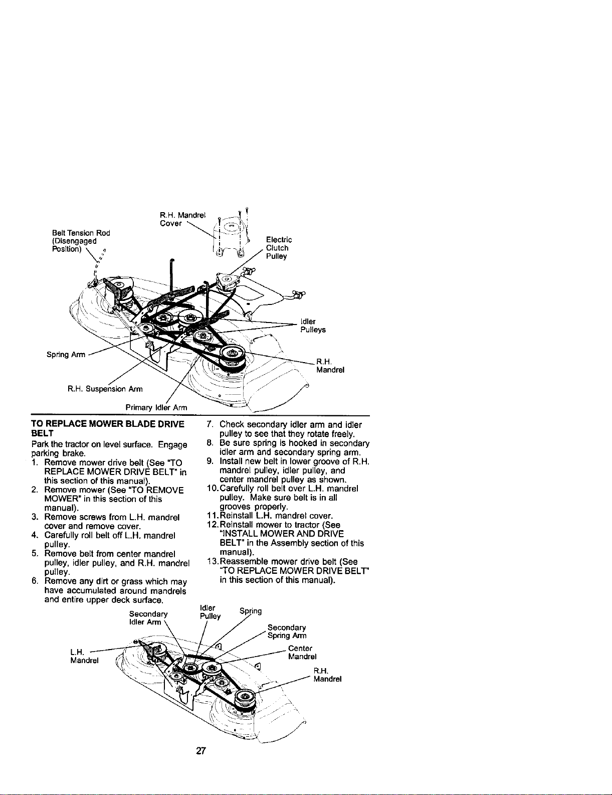
BeltTensionRod
(Disengaged
Position) _,;?
t/
R.H. Mandrel _t_ !
Electric
Clutch
Pulley
Idler
Pulleys
Spdng
R.H.
Mandrel
R.H. SuspensionArm -_ --I
PrimaryIdlerArm _:i_
TO REPLACE MOWER BLADE DRIVE
BELT
Park the tractoron level surface. Engage
parking brake.
1. Remove mower drive belt (See "TO
REPLACE MOWER DRIVE BELT" in
this section of this manual).
2. Remove mower (See "TO REMOVE
MOWER" in this section of this
manual).
3. Remove screws from L.H. mandrel
cover and remove cover.
4. Carefully roll belt off L.H. mandrel
pulley.
5. Remove belt from center mandrel
pulley, idler pulley,and R.H. mandrel
pulley.
6. Remove any dirtor grass which may
have accumulated around mandrels
and entire upper deck surface.
7. Check secondary idler arm and idler
pulley to see that they rotate freely.
8. Be sure spring is hooked in secondary
idler arm and secondary spring arm.
9. Install new belt in lower groove of R.H.
mandrel pulley, idler pulley, and
center mandrel pulley as shown.
1O.Carefully roll belt over L.H. mandrel
pulley. Make sure belt is in all
grooves properly.
11.Reinstall LH. mandrel cover.
12.Reinstall mower to tractor (See
"INSTALL MOWER AND DRIVE
BELT" in the Assembly section ofthis
manual).
13.Reassemble mower drive belt (See
=TOREPLACE MOWER DRIVE BELT"
in this section ofthis manual).
Secondary _uJ_lrey Sp_mg
IdlerArm \ / / Secondary
---- -_,_ / / / SpdngArm
LH __-_/_'/_'d / Center
Mandre_l f_'___"""_ Mandrel
.... , Mandre
27
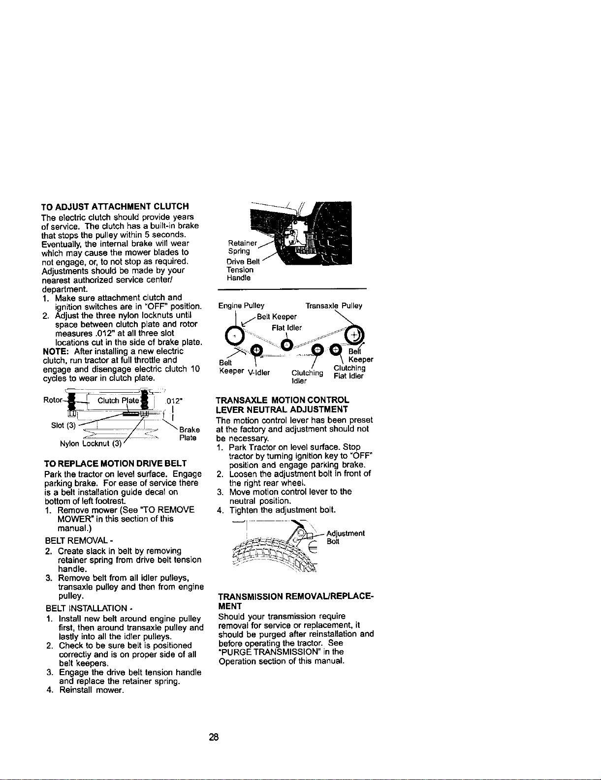
TO ADJUST ATTACHMENT CLUTCH
The electric clutchshould provide years
of service. The clutch has a built-inbrake
that stops the pulley within 5 seconds,
Eventually, the internal brake will wear
which may cause the mower blades to
notengage, or, to not stop as required.
Adjustments should be made by your
nearest authorized service center/
department.
1. Make sure attachment clutch and
ignition switches are in "OFF" position.
2. Adjust the three nylon Iocknuts until
space between clutch plate and rotor
measures ,012" at all three slot
locations cut in the side of brake plate.
NOTE: After installing a new electric
clutch, run tractorat full throttleand
engage and disengage electdc clutch 10
cycles towear in clutch plate.
___%-_,
Rotor-_----_-[_C utchPatel J 012"
J_/ \ l_ 1
s ot(3) Brake
ZiZ <:;
.,,o. Plats
TO REPLACE MOTION DRIVE BELT
Park the tractor on level surface. Engage
parkingbrake, For ease ofservice there
is a belt installation guide decal on
bottom of left footrest.
1. Remove mower (See "TO REMOVE
MOWER" in this sectionof this
manual.)
BELT REMOVAL -
2. Create slack in belt by removing
retainer spring from drive belt tension
handle.
3. Remove belt from all idler pulleys,
transaxle pulley and then from engine
pulley.
BELT INSTALLATION -
1. Install new belt around engine pulley
first, then around transaxle pulley and
lastly into all the idler pulleys.
2. Check to be sure belt is positioned
correctlyand is on proper side of all
belt keepers.
3. Engage the ddve belt tension handle
and replace the retainer spring,
4, Reinstall mower,
Retainer
Spring
Odve
Tension
Handle
EnginePulley Transaxle Pulley
se_ / / \ . P
Keeper V-Idler Clutching FCIu_i_dlnrg
Idler
TRANSAXLE MOTION CONTROL
LEVER NEUTRAL ADJUSTMENT
The motion control lever has been preset
at the factory and adjustment should not
be necessary.
1, Park Tractor on level surface, Stop
tractor by turningignitionkey to "OFF"
position and engage parking brake.
2, Loosen the adjustment bolt in front of
the right rear wheel.
3. Move motion control lever to the
neutral position.
4. Tighten the adjustment bolt.
__!_i .... _ ' AdjustmentBo_t
TRANSMISSION REMOVAL/REPLACE-
MENT
Should your transmission require
removal for service or replacement, it
should be purged after reinstallationand
before operating the tractor. See
"PURGE TRANSMISSION" inthe
Operation section of this manual.
28
TO ADJUST STEERING WHEEL ALIGN-
MENT
If steering wheel crossbars are not
horizontal (left to right) when wheels are
positionedstraight forward, remove
steering wheel end reassemble per
instructionsin the Assembly section of
this manual
FRONT WHEEL TOE-IN ADJUSTMENT
Front wheel toe-in is required for proper
steering operation. Toe-in was set at the
factory and adjustment should not be
necessary. If parts inthe front axle or
steering mechanism have been replaced
or damaged, check toe-in and adjust if
necessary,
TO CHECK TOE-IN -
1. Position front wheels straight ahead.
2. Measure distance between wheels at
front and rear of tires (dimensions "A"
and "B").
• Front dimension "A" should be 1/8" to
1/4" less than rear dimension "B".
TO ADJUST TOE-IN -
1. Loosen jam nuts at adjustment
sleeves on tie rod.
2. Adjust tie rod untildimension =A"is
1/8" to 1/4" less than dimension "B'.
3. Tighten jam nuts securely.
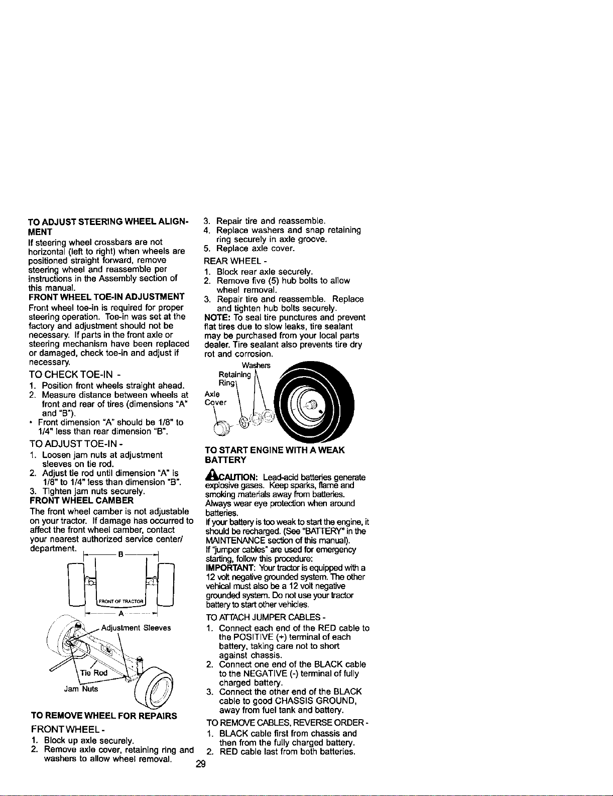
FRONT WHEEL CAMBER
The front wheel camber is not adjustable
on your tractor. If damage has occurred to
affect the front wheel camber, contact
your nearest authorized service center/
department. B
y//_z_djustrnent Sleeves
Jam Nuts
TO REMOVE WHEEL FOR REPAIRS
FRONTWHEEL-
1. Block up axle securely.
2. Remove axle cover, retaining ring and
3. Repair tire and reassemble.
4. Replace washers and snap retaining
ring securely in axle groove.
5. Replace axle cover.
REAR WHEEL -
1. Block rear axle securely.
2. Remove five (5) hub bolts to allow
wheel removal.
3. Repair tire and reassemble. Replace
and tighten hub bolts securely.
NOTE: To seal tire punctures and prevent
flat tires due to slow leaks, tire sealant
may be purchased from your local parts
dealer. Tire sealant also preventstire dry
rot and corrosion,
Washers
Retaining
Ring
Axle
Cover
TO START ENGINE WITH A WEAK
BATTERY
_bCAUTION: Lead-acidbatteries generate
explosivegases. Keep sparks, flameand
smoking materials away from batteries.
Always wear eye protection when around
batteries.
Ifyour battery is tee weak to startthe engine,it
should be recharged. (See "BAT[ERY" inthe
MAINTENANCE section of thismanual).
If"jumper cables" areused for emergency
star'dng,follow this procedure:
IMPORTANT: Yourtractoris equipped with a
12 volt negative grounded system.The other
vehical must also be a 12 volt negative
grounded system. Do not use yourb'actor
batteryto startother vehicles.
TO ATTACHJUMPER CABLES -
1. Connect each end of the RED cable to
the POSITIVE (+) terminal of each
battery, taking care not to short
against chassis.
2. Connect one end of the BLACK cable
to the NEGATIVE (-) terminal of fully
charged battery.
3. Connect the other end of the BLACK
cable to good CHASSIS GROUND,
away from fuel tank and battery.
TO REMOVECABLES, REVERSE ORDER -
1. BLACK cable first from chassis and
then from the fully charged battery.
2. RED cable last from both batteries.
washers to allow wheel removal. 29
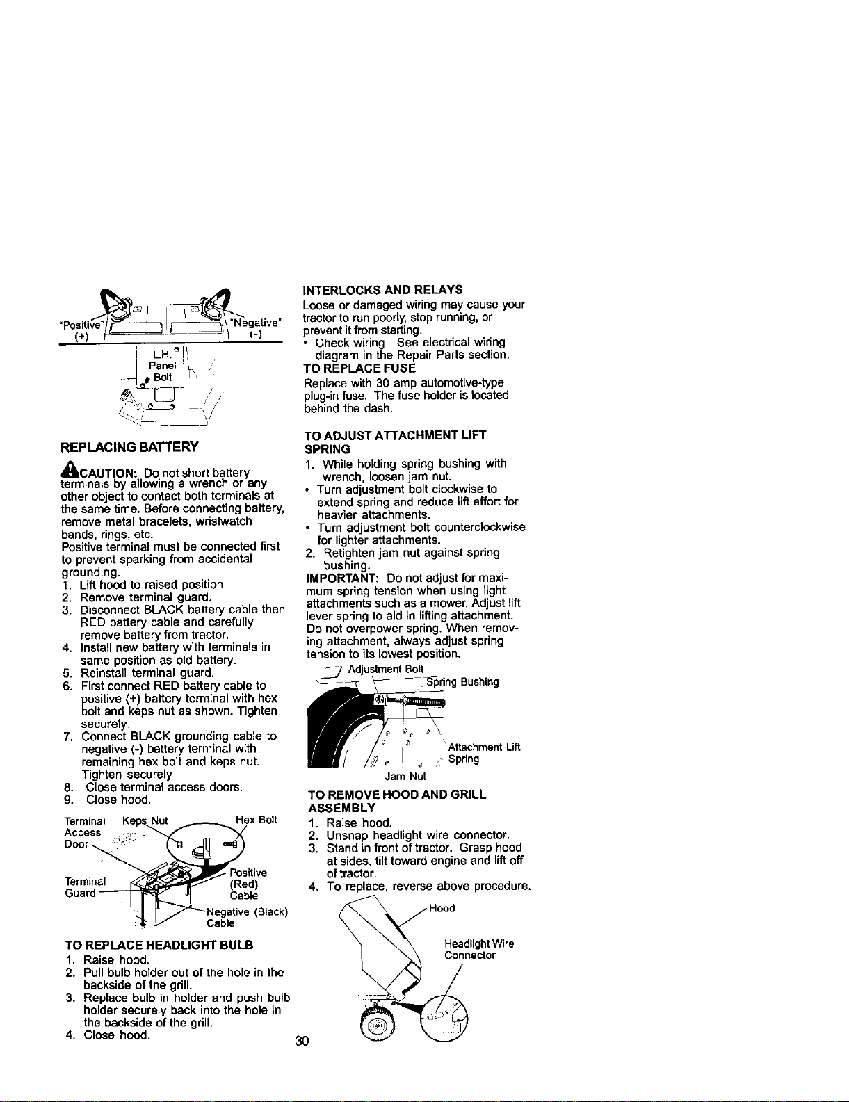
_ _anel _'
Bolt !
4. ,.L_ • /
":-_5 - 5'
REPLACING BATTERY
='t
4_CAUTION: Do not short battery
terminals by allowing a wrench or any
other object to contact both terminals at
the same time, Before connecting battery,
remove metal bracelets, wristwatch
bands, rings, etc.
Positiveterminal must be connected first
to prevent sparking from accidental
grounding.
1, Lift hood to raised position.
2. Remove terminal guard.
3. Disconnect BLACK battery cable then
RED battery cable and carefully
remove batteryfrom tractor.
4. Install new battery with terminals in
same positionas old battery.
5. Reinstall terminal guard.
6, First connect RED battery cable to
positive (+) battery terminal with hex
bolt and keps nut as shown. Tighten
securely,
7, Connect BLACK grounding cable to
negative (-) battery terminal with
remaining hex boltand keps nut.
Tighten securely
8. Close terminal access doors.
9. Close hood.
Termina_'_
Guard
Hex Bolt
_ _'sitive
(Red)
JI Cable
_"_ Negative (Black)
Cable
TO REPLACE HEADLIGHT BULB
1, Raise hood.
2. Pull bulb holder out of the hole in the
backside of the grill.
3. Replace bulb in holder and push bulb
holder securely back intothe hole in
the backside of the grill.
4. Close hood. 30
INTERLOCKS AND RELAYS
Looseor damaged wiring may cause your
tractorto run poorly,stoprunning,or
preventitfromstarting.
• Check wiring. See electrical wiring
diagram in the Repair Parts section.
TO REPLACE FUSE
Replace with 30 amp automotive-type
plug-infuse. The fuse holder is located
behind the dash.
TO ADJUST ATTACHMENT LIFT
SPRING
1. While holding spring bushing with
wrench, loosen jam nut.
• Turn adjustment boltclockwise to
extend springand reduce lift effortfor
heavier attachments.
• Turn adjustment bolt counterclockwise
for lighter attachments.
2. Retightan jam nut against spring
bushing.
IMPORTANT: Do not adjustfor maxi-
mum spring tension when using light
attachments such as a mower. Adjustlift
lever spring to aid in liftingattachment.
Do not overpower spring.When remov-
ing attachment, always adjust spring
tensionto its lowest position.
j AdjustmentBolt
Bushing
Attachment Lift
/ Spdng
Jam Nut
TO REMOVE HOOD AND GRILL
ASSEMBLY
1. Raise hood.
2. Unsnap headlight wire connector.
3. Stand in front oftractor. Grasp hood
at sides, tilt toward engine and liftoff
oftractor.
4. To replace, reverse above procedure,
Hood
HeadlightWire
octor
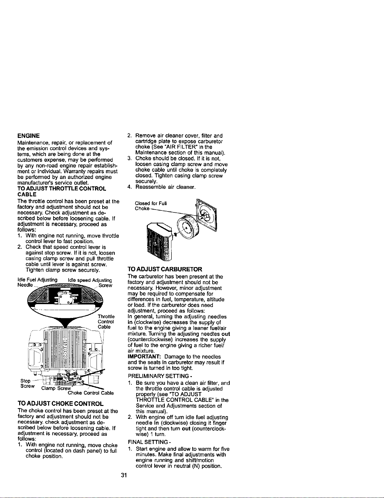
ENGINE
Maintenance, repair, or replacement of
the emission control devices and sys-
tems, which are being done at the
customers expense, may be performed
by any non-road engine repair establish-
ment or individual Warranty repairs must
be performed by an authorized engine
manufacturer's service outlet.
TO ADJUST THROTTLE CONTROL
CABLE
The throttlecontrolhas been preset at the
factory and adjustment should not be
necessary. Check adjustment as de-
scribed below before loosening cable, if
adjustment is necessary, proceed as
follows:
1. With engine notrunning, move throttle
control lever to fast position.
2. Check that speed control lever is
againststop screw. If it is not, loosen
casing clamp screw and pull throttle
cable until lever is against screw.
Tighten clamp screw securely.
Idle Fuel Adjusting Idle speed Adjusting
Needle Screw
Throttle
Control
Cable
I
I
[
Screw Clamp Screw /
Choke Control Cable
TO ADJUST CHOKE CONTROL
The choke control has been preset at the
factoryand adjustment should not be
necessary, check adjustment as de-
scribed below before loosening cable. If
adjustment is necessary, proceed as
follows:
1. With engine not running, move choke
control (located on dash panel) to full
choke position.
2. Remove air cleaner cover, filter and
cartddge plate to expose carburetor
choke (See "AIR FILTER" in the
Maintenance section of this manual).
3. Choke should be closed. If it is not,
loosen casing clamp screw and move
choke cable until choke is completely
closed. Tighten casing clamp screw
securely.
4. Reassemble air cleaner.
Closed for Full
TO ADJUST CARBURETOR
The carburetor has been present at the
factory and adjustment should not be
necessary. However, minor adjustment
may be required to compensate for
differences in fuel, temperature, altitude
or load. Ifthe carburetor does need
adjustment, proceed as follows:
In general, turning the adjusting needles
in (clockwise) decreases the supplyof
fuel to the engine giving a leaner fuel/air
mixture.Turning the adjusting needles out
(counterclockwise) increases the supply
offuel to the engine giving a richer fuel/
air mixture.
IMPORTANT: Damage to the needles
and the seats in carburetor may result if
screw isturned in too tight.
PRELIMINARY SETTING -
1. Be sure you have a clean air filter, and
the throttle control cable is adjusted
properly (see "TO ADJUST
THROTTLE CONTROL CABLE" in the
Service and Adjustments section of
this manual).
2. With engine off turn idle fuel adjusting
needle in (clockwise) closing it finger
tight and then turn out (counterclock-
wise) 1 turn.
FINAL SETTING -
1. Start engine and allow to warm for five
minutes. Make final adjustments with
engine running and shift/motion
control lever in neutral (N) position.
31
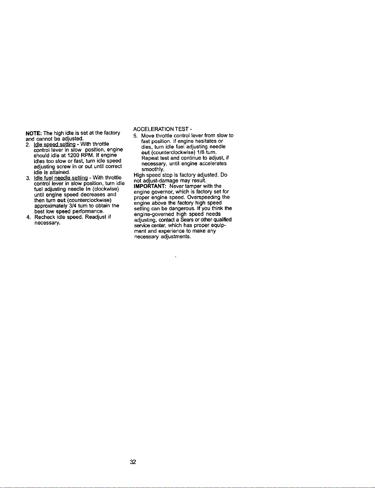
NOTE: The high idle is set at the factory
and cannot be adjusted.
2. Idle seeed settina - With throttle
controllever in slow position, engine
should idle at 1200 RPM. If engine
idles too slow or fast, turn idle speed
adjustingscrew in or out untilcorrect
idle is attained.
3. Idle fuel needle settina - With throttle
control lever in slow position, turn idle
fuel adjusting needle in (clockwise)
until engine speed decreases and
then turn out (counterclockwise)
approximately 3/4 turn to obtain the
best low speed performance.
4. Recheck idle speed. Readjust if
necessary.
ACCELERATION TEST -
5. Move throttlecontrol lever from slow to
fast position. If engine hesitates or
dies, turn idle fuel adjusting needle
out (counterclockwise) 1/8 turn.
Repeat test and continue to adjust, if
necessary, until engine accelerates
smoothly.
High speed stop is factory adjusted. Do
notadjust-damage may result.
IMPORTANT: Never tamper with the
engine governor, which isfactory set for
proper engine speed. Overspeeding the
engine above the factory high speed
setting can be dangerous. If you think the
engine-governed high speed needs
adjusting, contacta Sears orotherqualified
servicecanter, which has proper equip-
ment and experience to make any
necessary adjustments.
32
Immediately prepare your tractor for
storage at the end of the season or if the
tractor willnot be used for 30 days or
more,
_b CAUTION: Never store the tractor
with gasoline in the tank inside a building
where fumes may reach an open flame or
spark. Allow the engine to cool before
storing in any enclosure.
TRACTOR
Remove mower from tractor forwinter
storage. When mower is to be stored for
a period of time, clean it thoroughly,
remove all dirt, grease, leaves, etc. Store
in a clean, dry area.
1. Clean entire tractor (See =CLEANING"
in the Maintenance section of this
manual).
2. Inspect and replace belts, if necessary
(See belt replacement instructionsin
the Service and Adjustments section
of this manual).
3. Lubricate as shown in the Mainte-
nance section of this manual
4. Be sure that all nuts, bolts and screws
are securely fastened. Inspect moving
parts for damage, breakage and wear.
Replace if necessary.
5. Touch up all rusted or chipped paint
surfaces; sand lightly before painting.
BA'I'rERY
• Fully charge the battery for storage.
• After a period of time in storage, battery
may require recharging.
• To help prevent corrosion and power
leakage during long periods of storage,
battery cables should be disconnected
and battery cleaned thoroughly (see
=TOCLEAN BATTERY AND TERMI-
NALS" in the Maintenance section of
this manual).
• After cleaning, leave cables discon-
nected and place cables where they
cannot come in contact with battery
terminals.
• If battery is removed from tractor for
storage, do not store battery directly on
concrete or damp surfaces.
ENGINE
FUEL SYSTEM
IMPORTANT: It isimportant to prevent
gum deposites from forming in essential
fuel system parts such as carburetor,fuel
hose, or tank during storage. Also,
experiance indicates that alcohol
blended fuels (called gasohol or using
ethanol or methanol) can attract moisture
which leads to separation and formation
of acids during storage. Acidic gas can
damage the fuel system of and engine
while in storage.
1. Drain the fuel tank.
2. Start the engine and let it run until the
fuel lines and carburetor are empty.
• Never use engine or carburetor cleaner
products in the fuel tank or permanent
damage may occur.
• Use fresh fuel next season.
NOTE: Fuel stabilizer is an acceptable
alternative in minimizing the formation of
fuel gum deposits during storage. Add
stabilizer to gasoline in fuel tank or
storage container. Always follow the mix
ratio found on stabilizer container. Run
engine at least 10 minutes after adding
stabilizer to allow the stabilizer to reach
the carburetor. Do not drain the gas tank
and carburetor if using fuel stabilizer.
ENGINEOIL
Drain oil (with engine warm) and replace
with clean engine oil. (See "ENGINE" in
the Maintenance section of this manual).
CYLINDER(S)
1. Remove spark plug(s).
2. Pour one ounce of oil through spark
plug hole(s) into cylinder(s).
3. Turn ignition key to "START" position
for a few seconds to distribute oil.
4. Replace with new spark plug(s).
OTHER
• Do not store gasoline from one season
to another.
• Replace your gasoline can if your can
startsto rust. Rust and/or dirtin your
gasoline will cause problems.
• If possible, storeyour tractor indoors
and cover it to give protectionfrom dust
and dirt.
• Cover your tractor with a suitable
protective cover that does not retain
moisture. Do not use plastic. Plastic
cannot breathe which allows conden-
sation to form and will cause your
tractor to rust.
IMPORTANT: Never cover tractor while
engine and exhaust areas are stillwarm.
33
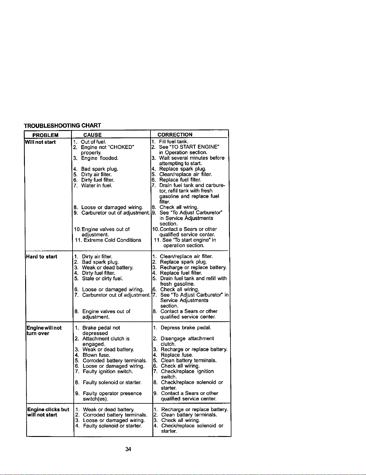
TROUBLESHOOTINGCHART
PROBLEM
Nill not start
Hard to start
Enginewill not
_umover
Engine clicks but
will not start
CAUSE
1. Out of fuel.
2. Engine not =CHOKED"
properly.
3. Engine flooded,
4. Bad spark plug.
5. Dirty air filter.
6. Dirty fuel filter.
7. Water in fuel.
8. Loose or damaged wiring.
9. Carburetor out of adjustment.
1O.Engine valves out of
adjustment.
11. Extreme Cold Conditions
1. Dirty air filter.
2. Bad spark plug.
3. Weak or dead battery.
4. Dirty fuel filter.
5. Stale or dirty fuel.
6. Loose or damaged wiring.
7. Carburetor out of adjustment.
8. Engine valves out of
adjustment.
1. Brake pedal not
depressed
2. Attachment clutch is
engaged.
3. Weak or dead battery.
4. Blown fuse.
5. Corroded battery terminals.
6. Loose or damaged wiring.
7. Faulty ignition switch.
8. Faulty solenoid or starter.
9. Faulty operator presence
switch(es).
1. Weak or dead battery.
2. Corroded battery terminals.
3. Loose or damaged wiring.
4. Faulty solenoid or starter.
CORRECTION
1. Fillfuel tank.
2. See "TO START ENGINE"
in Operation section.
3. Wait several minutes before
attempting to start.
4. Replace spark plug.
5. Clean/replace air filter.
6. Replace fuel filter.
7. Drain fuel tank and carbure-
tor, refill tank with fresh
gasoline and replace fuel
filter.
8. Check all wiring.
9. See "To Adjust Carburetor"
in Service Adjustments
section.
1O.Contact a Sears or other
qualified service center,
11. See "To start engine" in
operation section.
1. Clean/replace air filter.
2. Replace spark plug.
3. Recharge or replace battery.
4. Replace fuel filter.
5. Drain fuel tank and refill with
fresh gasoline.
3. Check all wiring.
t. See "To Adjust Carburetor" in
Service Adjustments
section.
3. Contact a Sears or other
qualified service center.
1. Depress brake pedal.
2. Disengage attachment
clutch.
3. Recharge or replace battery.
4. Replace fuse.
5. Clean battery terminals.
B. Check all wiring.
7. Check/replace ignition
switch.
8. Check/replace solenoid or
starter.
9. Contact a Sears or other
qualified service center.
1. Recharge or replace battery.
2. Clean battery terminals.
3. Check all wiring.
4. Check/replace solenoid or
starter.
34
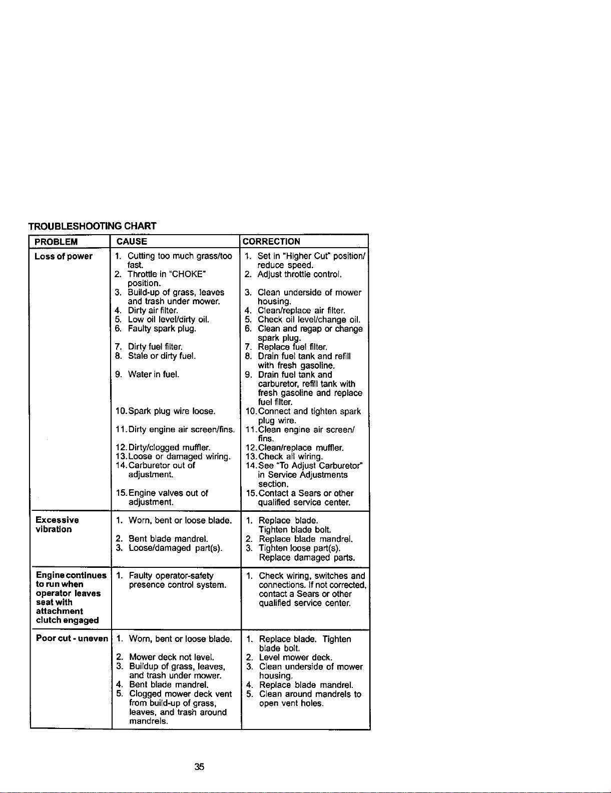
TROUBLESHOOTING CHART
PROBLEM CAUSE
Lossofpower 1, Cuttingtoo muchgrass_oo
Excessive
vibration
Engine continues
to run when
operator leaves
seat with
attachment
clutch engaged
Poor cut - uneven
fast.
2. Throttle in "CHOKE"
position.
3, Build-up of grass, leaves
and trash under mower,
4, Dirty air filter,
5. Low oil level/dirty oil.
6. Faulty spark plug.
7. Dirty fuel filter.
8. Stale or dirtyfuel
9. Water in fuel.
10.Spark plug wire loose,
11.Dirty engine air screen/fins.
12. Dirty/clogged muffler.
13,Loose or damaged wiring.
14,Carburetor out of
adjustment.
15.Engine valves out of
adjustment,
1. Worn, bent or loose blade.
2. Bent blade mandrel.
3, Loose/damaged part(s).
1. Faulty operator-safety
presence control system.
1. Worn, bent or loose blade.
2. Mower deck not level.
3. Buildup of grass, leaves,
and trash under mower.
4, Bent blade mandrel,
5. Clogged mower deck vent
from build-up of grass,
leaves, and trash around
mandrels.
CORRECTION
1. Set in "Higher Cut" position/
reduce speed.
2. Adjust throttle control,
3. Clean underside of mower
housing,
4. Clean/replace air filter.
5. Check oil level/change oil,
6. Clean and regap or change
spark plug.
7. Replace fuel filter,
8. Drain fuel tank and refill
with fresh gasoline.
9. Drain fuel tank and
carburetor, refill tank with
fresh gasoline and replace
fuel filter.
10.Connect and tighten spark
plug wire.
11.Clean engine air screen/
fins.
12.Clean/replace muffler.
13.Check all wiring.
14. See "To Adjust Carburetor"
in Service Adjustments
section.
15.Contact a Sears or other
qualified service center,
1. Replace blade.
Tighten blade bolt.
2. Replace blade mandrel.
3. Tighten loose part(s).
Replace damaged parts.
1. Check wiring, switches and
connections. If not corrected
contact a Sears or other
qualified service center.
1, Replace blade. Tighten
blade bolt.
2. Level mower deck.
3, Clean underside of mower
housing.
4, Replace blade mandrel,
5, Clean around mandrels to
open vent holes.
35
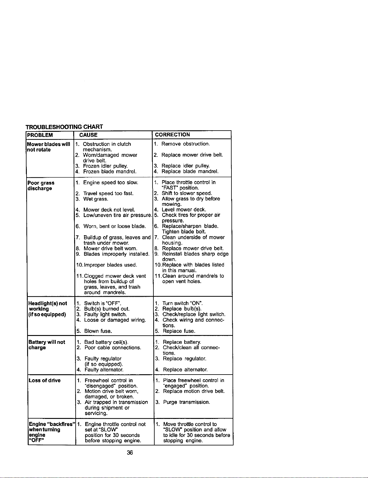
TROUBLESHOOTING CHART
PROBLEM CAUSE CORRECTION
_lowerbladeswill 1, Obstruction in clutch 1. Remove obstruction,
riotrotate mechanism,
2. Worn/damaged mower 2, Replace mower drive belt,
drive belt.
3. Frozen idler pulley. 3. Replace idler pulley.
4. Frozen blade mandrel. 4. Replace blade mandrel.
Poor grass 1. Engine speed too slow.
discharge
Headlight(s) not
working
(if so equipped)
2. Travel speed too fast.
3. Wet grass.
4, Mower deck not level.
5. Low/uneven tire air pressure
6. Worn, bent or loose blade.
;7. Buildup of grass, leaves and
trash under mower.
8. Mower drive belt worn.
9. Blades improperly installed.
10.Improper blades used.
11.Clogged mower deck vent
holes from buildup of
grass, leaves, and trash
around mandrels.
1. Switch is "OFF".
2. Bulb(s) burned out.
3. Faulty light switch.
4, Loose or damaged wiring.
5. Blown fuse.
Battery will not
icharge
3.
4.
Loss of drive 1.
2.
3.
Engine "backfires" 1.
_/henturning
snglne
"OFF"
1. Bad battery ceil(s).
2. Poor cable connections.
Faulty regulator
(if so equipped).
Faulty alternator.
Freewheel control in
"disengaged" position.
Motion drive belt worn,
damaged, or broken.
Air trapped in transmission
during shipment or
servicing.
1. Place throttle control in
"FAST" position.
2. Shift to slower speed.
3. Allow grass to dry before
mowing.
4, Level mower deck.
5. Check tires for proper air
pressure.
6. Replace/sharpen blade.
Tighten blade bolt.
7. Clean underside of mower
housing.
8. Replace mower drive belt.
9. Reinstall blades sharp edge
down.
10.Replace with blades listed
in this manual.
11.Clean around mandrels to
open vent holes.
1. Turn switch"ON".
2. Replace bulb(s).
3. Check/replace light switch.
4. Check wiring and connec-
tions.
5. Replace fuse.
1. Replace battery.
2. Check/clean all connec-
tions,
3. Replace regulator.
4. Replace alternator.
1. Place freewheel control in
=engaged" position.
2. Replace motion drive belt.
3, Purge transmission.
Engine throttle control not 1. Move throttle control to
set at "SLOW" "SLOW" position and allow
position for 30 seconds to idle for 30 seconds before
before stopping engine, stopping engine.
36
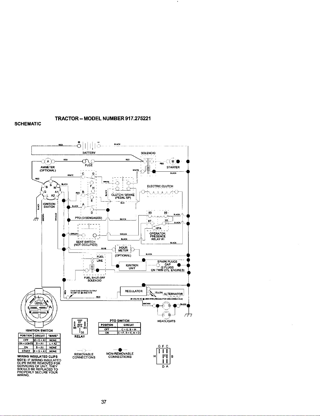
SCHEMATIC
TRACTOR - MODEL NUMBER 917.275221
WIRING tN5ULATED CLtP_
NOTE: IF WIRING INSULATED
CLIPS WERE REMOVED FOR
SERVICING OF UNIT, THEY
,5t_::Y_LE) I_E _EPLACED TO
PROPERLY SECURE YOUR
WIRING,
REMOVABLE
CONNECTIONS
NON-REMOVABLE
CONNECTtONS
GFC
DA
37
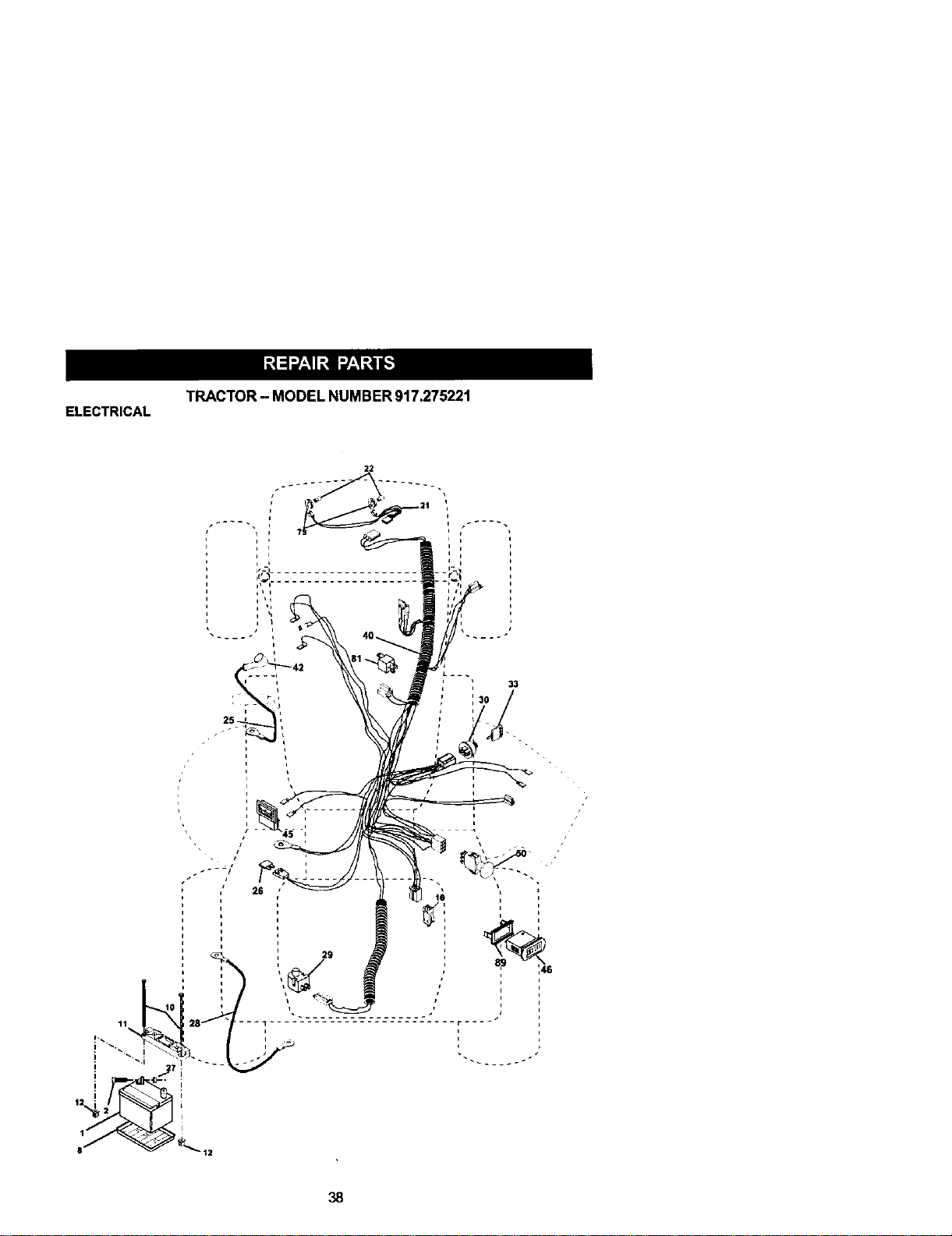
TRACTOR - MODEL NUMBER 917.275221
ELECTRICAL
22
33
38

ELECTRICAL
TRACTOR - MODEL NUMBER 917.27522t
KEY PART
NO. NO. DESCRIPTION
1 144927 Batte_
2 74760412 Bolt Hex Head 114-20 x 3/4
8 7603J Tray, Battery
10 145211 Bolt 1/4-20 x 7.5 Zinc
11 150109 Hold down Battery Dash Mount
12 145769 Nut Push Nylon 1/4"
16 153664 Switch Interlock Push-In
21 166184 Harness Socket Light W/4152J
22 4152J Bulb Light
25 150755 Cable. Battery
26 108824X Fuse
27 73510400 Nut Keps Hex 1/4-20 Unc
28 170697 Cable.Ground
29 160784 Switch, Plunger
30 175566 Switch, Ign
33 140403 Key, Ignition
40 170238 Harness Ign.
42 154336 Cover, Terminal
45 12282ZX Ammeter
46 169635 Houn'nete_
50 174652 Switch, PTO
79 163996 Bulbholder Asm Incandescent BV
81 109748X Relay Asm.
89 169639 Bracket Snap-In Hourmeter
NOTE: All component dimensions given in U. S.
inches 1 inch = 25.4 mm
39
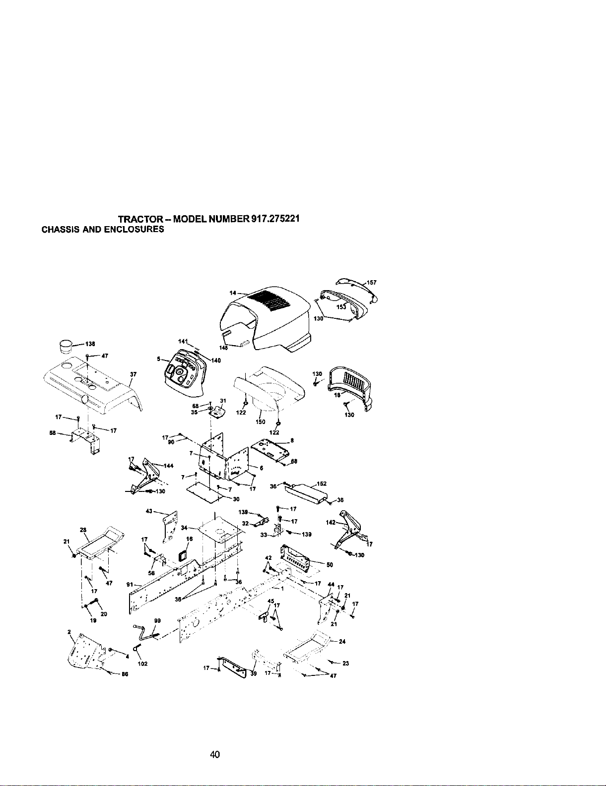
TRACTOR- MODELNUMBER917.275221
CHASSISANDENCLOSURES
17--._, I
157
37
150
122
130
i i
19
102 _- 23
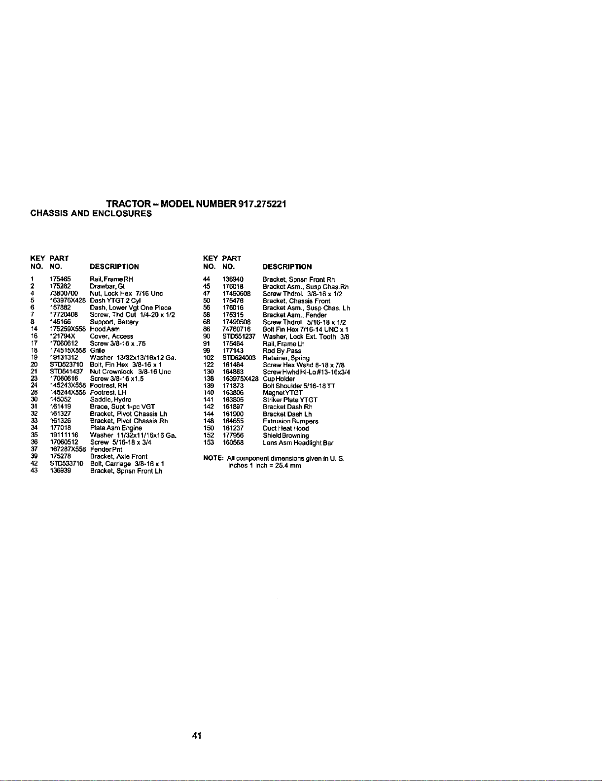
TRACTOR- MODEL NUMBER 917.27522t
CHASSIS ANDENCLOSURES
KEY PART KEY PART
NO. NO. DESCRIPTION NO. NO. DESCRIPTION
1 175465 Rail.Frame RH 44 136940 Bracket, Spnsn Front Rh
2 175282 Drawbar, Gt 45 176018 Bracket Asm., Susp Chas.Rh
4 73800700 Nut, Lock Hex 7116 Unc 47 17490608 Screw Thdrol. 3/8-16 x 1/2
5 153976)(428 Dash YTGT 2 Cyl 50 175476 Bracket, Chassis Front
6 157882 Dash, Lower Vgt One Piece 56 176016 Bracket Asm., Susp Chas, Lh
7 17720408 Screw. Thd Cut 1/4-20 x 1/2 58 175315 Bracket Asm., Fender
8 145166 Support, Battery 68 17490508 Screw Thdrol. 5/18-18 x 112
14 17525gx558 Hood Asm 86 74760716 Bolt Fin Hex 7/16-14 UNC x 1
16 121794X Cover, Access 90 STD551237 Washer, Lock Ext. Tooth 3/8
17 17060612 Screw 3/8_16 x .75 91 175464 Rait, Frame Lh
15 174515X558 Grille 99 177143 Rod By Pass
19 19131312 Washer 13/32x13/16x12Ga, 102 8_n_o24003 Retainer, Spring
20 STD523710 Bolt, Fin Hex 3/8-16 x 1 122 161464 Screw HexWshd 8-18x 7/8
21 s'rD541437 NutCrowniock 3/8-16Unc 130 164863 ScrewHwhdHi-Lo#18-16x3/4
23 17060616 Screw 3/5-16 x1,5 138 163975X428 CupHolder
24 145243X558 Footrest, RH 139 171873 BoltShoulder5/16-18TF
28 145244)(558 Footrest, LH 140 163806 MagnetYTGT
30 145052 Saddle, Hydro 141 1_3805 Striker Plate YTGT
31 161419 Brace, Supt 1-pcVGT 142 161897 Bracket Dash Rh
32 161327 Bracket, Pivot Chassis Lh 144 161900 Bracket Dash Lh
33 161326 Bracket, Pivot Chassis Rh 148 164655 Extrusion Bumpers
34 177018 Plate Asm Engine 150 161237 Duct Heat Hood
35 19111116 Washer 11/32x11/16x16Ga. 152 177956 ShieldBrowning
36 17060512 Screw 5/18-18 x 3/4 153 160568 LensAsmHeadlight Bar
37 167287X558 Fender Pnt
39 175278 Bracket, Axle Front NOTE: All component dimensions given in U. S.
42 STD533710 Bolt, Carriage 3/8-16xl inches1 inch=25.4mm
43 136939 Bracket, Spnsn Front Lh
41
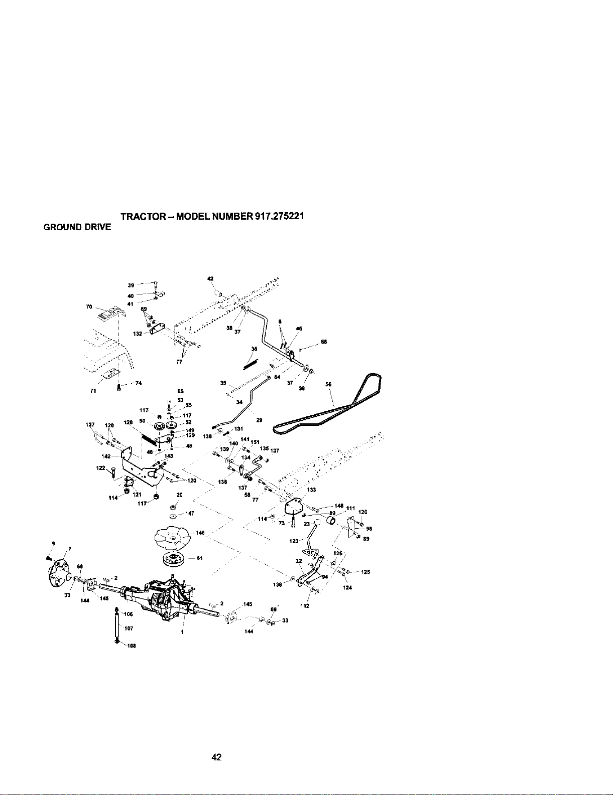
TRACTOR- MODELNUMBER917.275221
GROUNDDRIVE
117_
127 120 \
_129
48
68
36
133
120
$9
144
_2
_106
• 107
_108
_2 145
t44
22
/
112
6g
125
\
124
42
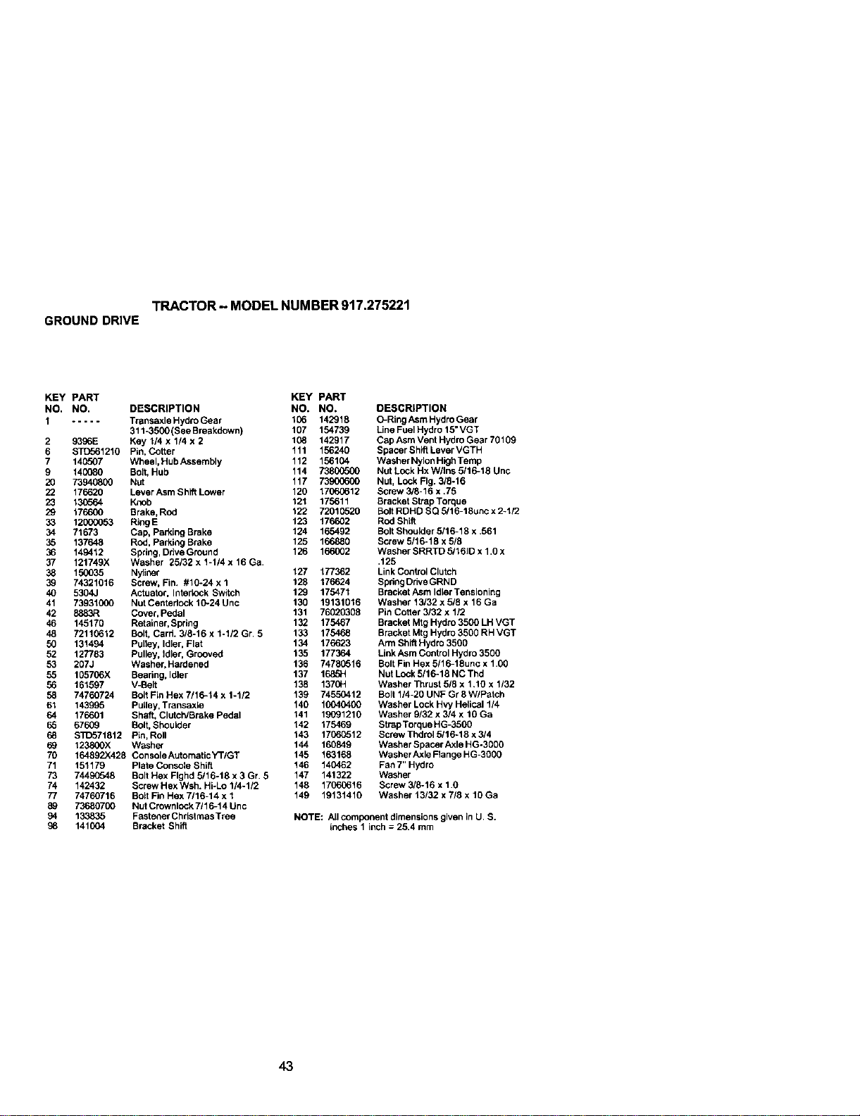
TRACTOR - MODEL NUMBER 917.275221
GROUNDDRIVE
KEY PART KEY PART
NO. NO. DESCRIPTION NO. NO.
I ..... Transaxle Hydro Gear 106 142918
311_500 (See Breakdown) 107 154739
2 9396E Key 1/4 x 1/4 x 2 108 142917
6 STD561210 Pin, Cotter 111 156240
7 146507 Wheel, Hub Assembly 112 156104
9 140080 Bolt, Hub 114 73800500
20 73940800 Nut 117 73_To00
22 176620 Lever Asm Shift Lower 120 17060612
23 130564 Knob 121 175611
29 176600 Brake, Rod 122 72010520
33 12000053 RingE 123 176602
34 71673 Cap, Parking Brake 124 165492
35 137648 Rod, Parking Brake 125 166880
36 149412 Spdng, Ddve Ground 126 166002
37 121749X Washer 25132 x 1-114 x 16 Ga.
38 150035 Nyliner 127 177362
39 74321016 Screw, Fin. #16-24 x 1 128 176624
40 5304J Actuator, Interlock Switch 129 175471
41 73931000 Nut Centedock 10-24Unc 130 19131016
42 8883R Cover, Pedal 131 76020308
46 145170 Retainer, Spring 132 175467
48 72110612 Bolt, Card. 3/8-16 x 1-1/2 Gr. 5 133 175468
50 131494 Pulley, Idler. Flat 134 176623
52 127783 Pulley, Idler, Grooved 135 177364
53 207J Washer, Hardened 136 74760516
55 105706X Bearing, Idler 137 168._1
56 161597 V-Belt 138 1370H
58 74760724 Bolt Fin Hex 7/16-14 x 1-1/2 139 74550412
61 143995 PuLley,Transaxle 140 10040400
64 176601 Shaft, Clutch/Brake Pedal 141 19091210
65 67609 Bolt, Shoulder 142 175469
68 S]C571812 Pin, Roll 143 17060512
69 123800X Washer 144 160849
70 164892)(428 ConsoleAutomaticYTIGT 145 163168
71 151179 Plate Console Shift 146 140462
73 74490548 Bolt Hex Flghd 5/16-18 x 3 Gr. 5 147 141322
74 142432 ScrewHexWsh. Hi-Lo 1/4-112 148 17060616
77 74760716 Bolt Fin Hex 7/16-14 x 1 149 19131410
89 73680700 Nut CrownloCk 7/10-14 Unc
94 133835 Fastener Christmas Tree
98 141004 Bracket Shift
DESCRIPTION
O-Ring Asm Hydro Gear
Line Fuel Hydro 15" VGT
Cap Asm Vent Hydro Gear 70109
Spacer Shift Lever VGTH
Washer Nylon High Temp
Nut Lock Hx Wllns 5/16-18 Unc
Nut, Lock Fig. 3/8-16
Screw 3/8-16 x .75
Bracket Strap Torque
Bolt RIDHC SQ 5/16-18unc x 2-1/2
Red Shift
Bolt Shoulder 5/16-18 x .561
Screw 5/16-18 x 5/8
Washer SRRTD 5/1610 x 1.0 x
.125
Link Control Clutch
Spdng Ddve GRND
Bracket Asm Idler Tensioning
Washer 15/32 x 5/8 x 16 Ga
Pin Cotter 3/32 x 1/2
Bracket Mtg Hydro 3500 LHVGT
Bracket Mtg Hydro 3500 RH VGT
Arm Shift Hydro 3500
Link Asm Control Hydro 3500
Bolt Fin Hex 5/16-18unc x 1.00
Nut Lock 5/16-18 NC Thd
Washer Thrust 5/8 x 1.10 x 1132
Bolt 114-20 UNF Gr 8 W/Patch
Washer Lock Hvy Helical 1/4
Washer 9/32 x 3/4 x 10 Ga
StrapTorque HG-3500
Screw Thdrol 5/16-18 x 3/4
Washer Spacer Axle HG-3000
Washer Axle Flange HG-3000
Fan 7" Hydro
Washer
Screw 3/6-16 x 1.O
Washer 13132 x 7/8 x 10 Ga
NOTE: All component dimensions given in U. S.
inches 1 inch = 25.4 mm
43
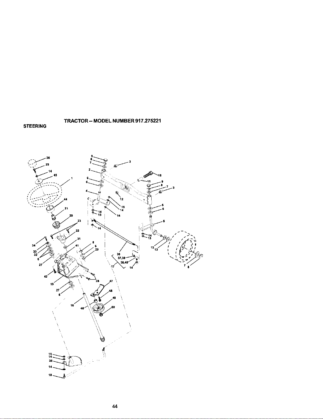
STEERING
TRACTOR-- MODEL NUMBER 917.275221
21
20
22
34
32
6
27
42
19
27 _
6'
16
\
\
'/
\
\
23
44

STEERING
TRACTOR - MODEL NUMBER 917.275221
KEY PART
NO. NO. DESCRIPTION
1 159944X428 Wheel, Steedng
2 137094 Axle Asm., Front
3 6855M Fitting, Grease
4 161849 Spindle Asm, LH
5 161848 Spindle Asm., RH
6 6266H Beadng, Race Thrust Harden
7 121748X Washer 25/32 x 1-5/8 x 16 Ga.
8 12000029 Ring, Klip#T5304-75
9 121232X Cap, Spindle
10 74781044 BoJt,Fin Hex 5/8-11 x 2-3/4
11 136518 Spacer Beadng AXle Front
12 73901000 Nut, Lock Flange 5/8-11 Unc
13 121749X Washer 25/32 x 1-1/4 x 16 Ga.
14 STD551137 Washer, Lock Hvy HIcl Spr 3/8
15 ST1_41537 Nut, Lock Center 3/8-24 UNF
16 145103 Shaft Asm., Steedng
17 137347 Rod Asm., Tie Ball J Ball Vgt (Inc. Key No. 36-40)
18 175572 Draglink Vgt
19 156011 Supgert Asm., Steering Vgt
20 163887X428 Boot, Steering
21 159945 Adapter. Wheel Steering
22 155105 Bushing. Strg. BIk
23 152927 Screw
25 74780616 Bolt, Fin Hex 3/8ol 6 x 1 Gr. 5
26 159946X428 Cap, Wheel Steering
27 3366R Bearing, Col. Strg.
28 176(_612 Screw, 3/8-16 x 3/4
29 104239X Bearing,Flange
31 138136 Bushing, Nyliner Snap
32 19111610 Washer 11/32 x 1 x 10 Ga.
33 STD551131 Washer, Lock Hvy Hid Spr 5/16
34 74780512 Bolt Fin Hex 5/16-18unc x 3/4
35 138059 Gear, Sector Steedng
36 137156 Tie Rod
37 73360600 Jam Nut RH Thread
38 109850X Joint Asm. BallRH Thread
39 7370(_000 Jam Nut LH Thread
40 109851X Joint Asm. Ball LH Thread
41 155246 Bracket Switch Interlock VGT 97
42 17490508 Screw Thdrol 5/16-18 x 1/2 Tyt
44 160135X428 Extension, Steering
45 19132411 Washer 13/32 x 1-1120 x 11 Ga.
46 178291 Spacer .407 x .625 x .500
47 177863 Bracket Asm Idler Stationaly
48 17060612 Screw 3/8-16 x .75
49 131494 Pulley Idler Flat
50 73900600 Nut Lock Fig 3/6-16 UNC
NOTE: AIIcomponent dimensions given in U. S.
inches 1 inch = 25.4 mm
45
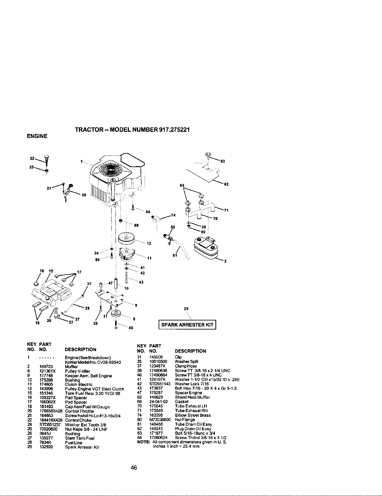
ENGINE
TRACTOR - MODEL NUMBER 917.275221
18 15 _t7
37
-47 \ 10
16
39
26
\
\
L SPARK ARRESTER KIT J
KEY PART
NO. NO.
1 ......
2 149723
8 121361X
9 177748
10 175288
11 174605
12 143996
15 151346
16 1G9227X
17 106082X
18 161493
20 176635X428
21 164863
22 164416X428
24 ST[T.551237
25 73920600
26 3645J
27 135277
28 7834R
29 132920
DESCRIPTION
Engine(See Breakdown)
KohlerModel No. CV26-69540
Muffler
Pulley V-Idler
Keeper Asm. Belt Engine
Bushing
Clutch Electric
Pulley Engine VGT Elect Clutch
Tank Fuel Rear 3,50 Yt/Gt 96
Pad Spacer
Pad Spacer
Cap Asm Fuel W/Gauge
ControlThrottle
Screw hwhd Hi-Lo #13-16x314
ControlChoke
Washer Ext Tooth 3/8
Nut Keps 3/8 - 24 UNF
Bushing
Stem Tank Fuel
FuelLIne
Spark Arrester Kit
KEY PART
NO. NO. DESCRIPTION
31 145006 CJip
35 10010500 Washer Split
37 123487X Clamp Hose
39 17490636 Screw TT 3/8-16 x 2-114 UNC
40 174_064 Screw TT 3/8-16 x 4 UNC
41 126197X Washer 1-112OD x15132 IDx ,250
42 STD551143 Washer Lock 7/16
43 173937 Bolt Hex 7/16 - 20 X 4 x Gr 5-1,5
47 175287 Bbecer Engine
62 146629 Shield Heat Muffler
69 24-041-02 Gasket
70 175545 Tube Exhaust LH
71 175548 Tube Exhaust RH
74 162295 Elbow Street Brass
80 M73030800 NutFlange
81 148456 Tube Drain Oil Easy
82 148315 Plug Drain Oil Easy
83 171877 Bolt 5/16-18unc x 3/4
84 17060624 Screw Thdrol 3/8-16 x 1-1/2
NOTE: All component dimensions given in U. S.
inches 1 inch = 25,4 mm
46
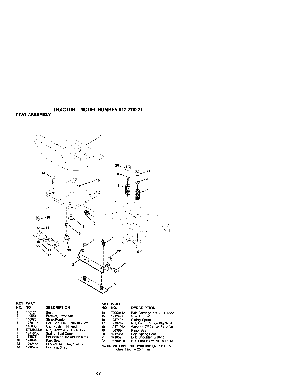
TRACTOR--MODELNUMBER917.275221
SEATASSEMBLY
21
KEY PART
NO. NO. DESCRIPTION
1 140124 Seat
2 140551 Bracket, Pivot Seat
3 146675 Strap, Fender
4 127018X Bolt, Shoulder 5116-18 x .62
5 145006 Clip, Push In, Hinged
6 STD541437 Nut, Crownlock 3/8-16 Unc
7 124181X Spring, Seat Cprsn
8 171877 Bolt 5116-18Uncx3/4 w/Seres
10 174894 Pan. Seat
12 121246X Bracket, Mounting Switch
13 121248X Bushing, Snap
KEY PART
NO. NO. DESCRIPTION
14 72050412 Bolt, Cardage 1/4-20 X 1-1/2
15 121249X Spacer, Split
16 123740)( Spring, Cprsn
17 123976X Nut. Lock 1/4 Lge Fig Gr 5
18 19171912 Washer 17/32x1-3/16x12 Ga.
19 166369 Knob, Seat
20 124238X Cap, Spdng Seat
21 171852 Bolt, Shoulder 5/16-18
22 73800500 Nut, Lock Hx wllns. 5/16-18
NOTE: All component dimensions given inU. S.
inches 1 inch = 25.4 mm
47
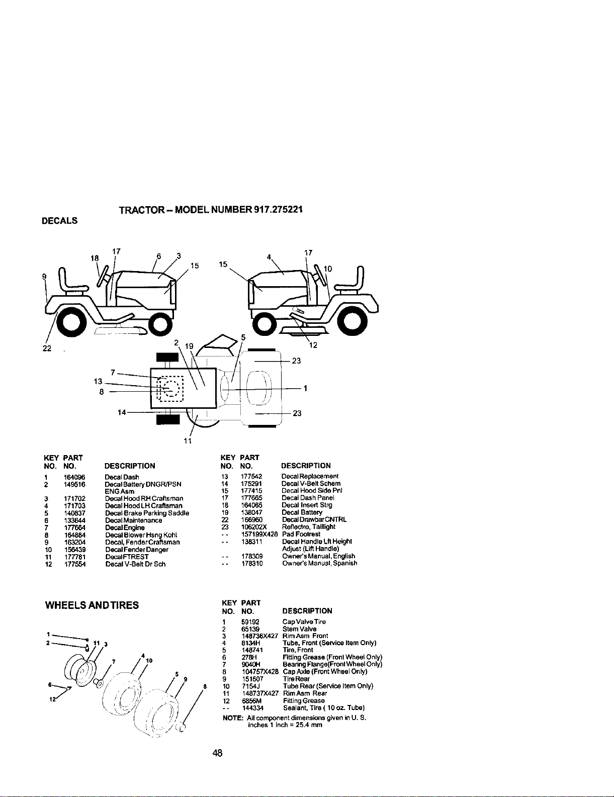
DECALS
TRACTOR- MODEL NUMBER 917.275221
18
17
15
15
17
22
12
KEY PART
NO. NO.
1 164096
2 149516
3 171702
4 171703
5 140837
6 133644
7 177664
8 164884
9 163204
10 156439
11 177781
12 177554
11
DESCRIPTION
DecalDash
Decal Battery DNGR/PSN
ENGAsm
Decal Hood RH Craftsman
Decal Hood LH Craftsman
Decal Brake Parking Saddle
Decal Maintenance
Decal Engine
Decal Blower Hsng Koh[
Decal, Fender Craftsman
Decal Fender Danger
DecalFTREST
Decal V-Belt Dr Sch
KEY PART
NO. NO. DESCRIPTION
13 177542 Deca_Replecement
14 175291 Oecal VoBeltScbem
15 177415 Decal Hood Side Pnl
17 177665 Decal Dash Panel
15 164065 Decal Insert Stpg
19 138047 Decal Batter/
22 166960 Decal Drawber CNTRL
23 106202X Reflectm, Taillight
- - 157199X428 Pad Footrest
-- 138311 Decal Handle Lft Height
Adjust (LiftHandle)
- - 178309 Owner's Manual, English
-* 178310 Owner's Manual, Spanish
WHEELS ANDTIRES
i\
KEY PART
NO. NO. DESCRIPTION
1 59192 Cap Valve Tire
2 65139 Stem Valve
3 148736X427 RimAsm Front
4 8134H Tube, Front (Service Item Only)
5 148741 Tim, Front
6 278H FittingGrease (Front Wbeel Only)
7 904_H Beadng Flenge(Front Wheel Only)
8 104757X428 Cap Axle (Front Wheel Only)
9 151607 TireRear
10 7154J Tube Rear (Service Item Only)
11 148737X427 RimAsm Rear
12 6856M FiftingGrease
- - 144334 Sealant, Tire ( 10 oz. Tube)
NOTE: All component dimensions given in U. S.
inches I inch = 25.4 mm
48
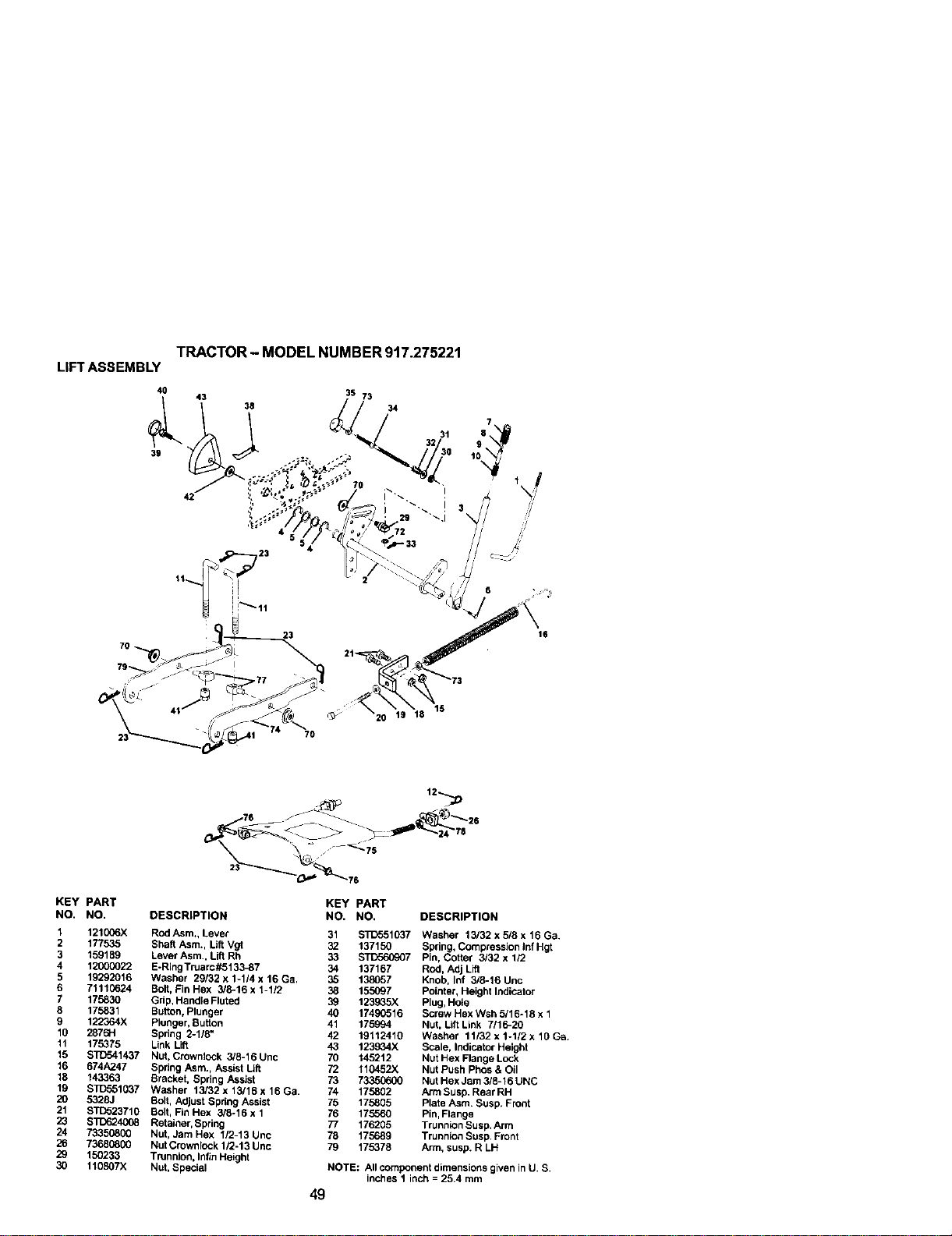
LIFT ASSEMBLY
40
39
TRACTOR - MODEL NUMBER 917.275221
43
42
35 73
38 34
32 31 _
30 10
23
7O
KEY PART
NO. NO.
1 121006X
2 177535
3 159189
4 12000022
5 19292016
6 71110624
7 175830
8 175831
9 122364X
10 2876H
11 175375
15 ST{354_437
16 674A247
18 143363
19 STD551037
2O 5328J
21 STO523710
23 ST1_2.4CO8
24 73350800
26 73680800
29 150233
30 110807X
12--_
75
KEY PART
OESCRtPTtON NO. NO. DESCRiPTiON
Rod Asm., Lever 31 $33_51037 Washer 13/32x5/8x16Ga.
Shaft Asm., Lilt Vgt 32 137150 Spring, Compression Inf Hgt
Lever Asm., Lift Rh 33 STD560907 Pin, Cotter 3/32 x 1/2
E*Ring Truarc#5133_7 34 137167 Rod, Adj Lift
Washer 29132 x 1-1/4 x 16 Ga. 35 138057 Knob, Inf 3/8-16 Unc
Bolt, Fin Hex 3/8-16 x 1-112 38 155097 Pointer, Height Indicator
Grip,Handle Fluted 39 123935X Plug.Hole
Button, Plunger 40 17490516 Screw Hex Wsh 6/16-18 x 1
Pionger, Button 41 175994 Nut, LiftLink 7116-20
Spring 2-1/8" 42 19112410 Washer 11/92 x 1-1/2 x 10 Ga.
Link Lift 43 123934X Scale, Indicator Height
N_, Cr_wntock 316-16 Unc 70 "_462"_2 NUt Hex Flar_geLock
Spring Asm., Assist Lift 72 110452X Nut Push Phos & Oil
Bracket, Spring Assist 73 73350600 Nut Hex Jam 3/8-16 UNC
Washer 13/32 x t3/16 x 16 Ga. 74 175802 Arm Susp. Rear RH
Bolt, Adjust Spdng Assist 75 175805 Plate Asm. Susp. Front
Bolt, Fin Hex 3/6-16 x 1 76 175560 Pin,Flange
Retainer, Spring 77 176205 Trunnion Susp.Arm
Nut, Jam Hex 112-13 Unc 76 175689 Trunnion Susp. Front
NutCrownlock 1/2-13 Unc 79 175378 Arm, susp. R LH
Trunnion, Infin Height
Nut, Special NOTE; All component dimensions given inU. S.
inches 1 inch = 25.4 mrn
49
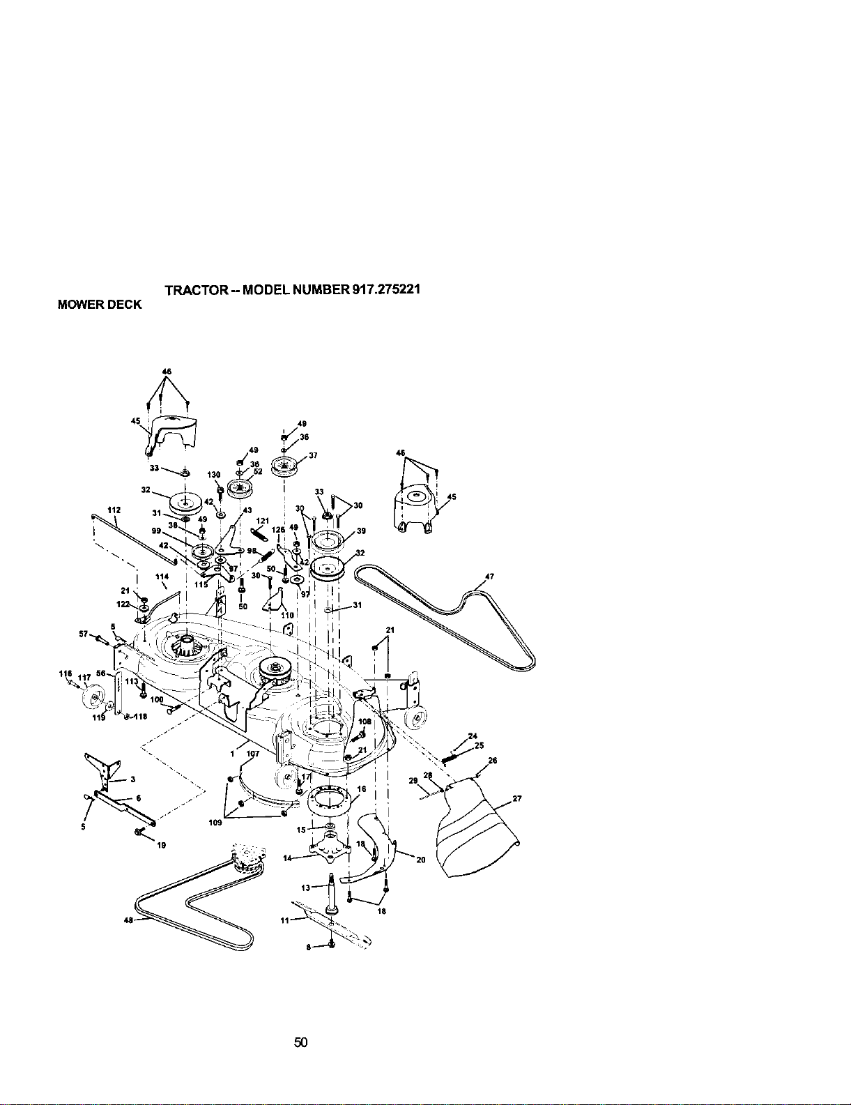
TRACTOR- MODELNUMBER917.275221
MOWERDECK
46
, 49
1_,0 ,
I
47
19
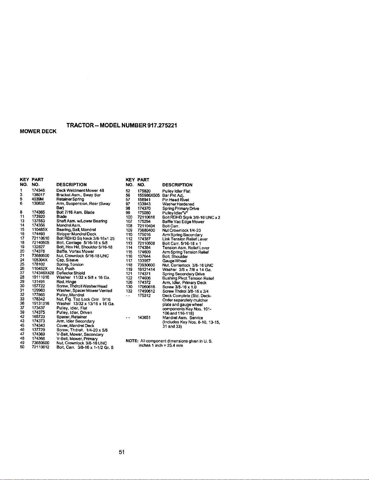
TRACTOR-- MODEL NUMBER 917.275221
MOWERDECK
KEY PART KEY PART
NO. NO. DESCRIPTION NO. NO.
1 174348 Deck Weldment Mower 48 52 175820
3 138017 Bracket Asm., Sway Bar 56 155986X505
5 4939M Retainer Spdng 57 156941
6 130832 Arm, Suspension, Rear(Sway 97 133943
Bar) 98 174370
8 174365 Bolt 7116 Asm. Blade 99 175080
11 173920 Blade 100 72110616
13 137553 Shaft Asm. w/Lower Beadn 9 167 175294
14 174356 MandrelAsm, 108 72110404
15 110485X Bearing, Bali, Mandrel 109 73680400
16 174493 Stdpper MandrelDeck 110 175016
17 72110610 Bolt RDHD Sq Neck 3/6-16xl,25 112 174387
18 72140505 Bolt, Carriage 5/16-18 x 5/8 113 72110508
19 132827 Bolt, Hex Hd, Shoulder 5116-18 114 174384
20 174378 Baffle, Vortax Mower 115 174609
21 73686500 Nut, Crownlock 5116-18UNC 116 137644
24 165304X Cap, Sleeve 117 133957
25 178102 Spring,Torsion 118 73930600
26 110452X Nut, Push 119 19121414
27 174346)(428 Deflector Shield 121 174371
28 19111016 Washer 11/32 x 5/8 x 16 Ga. 122 174606
29 131491 Rod, Hinge 126 174372
30 157722 Screw. ThdrollWasher Head 130 17060616
31 129963 Washer, Spacer Mower Mentod 132 17490612
32 177865 Pulley,Mandrel - - 175312
33 178342 Nut. Fig. Top LockCntr. 9/16
36 19131316 Washer 13/32 x 13/16 x 16 Ga.
37 173437 Pulley, Idler, Flat
39 174375 Pulley, Idler, Driven
42 165723 Spacer, Retainer °- 143651
43 174373 Arm, Idler Secondary
45 174343 Cover, Mandrel Deck
46 137729 Screw, Thdrolh 114-20 x 5/8
47 174369 V-Belt, Mower, Secondary
48 174368 V-Belt, Mower, Pdmary
49 73680600 Nut, Crownlock 3/6-16 UNC
50 72110612 Bolt, Cart. 3/8-16 x 1-1/2 Gr. 5
DESCRIPTION
Pulley Idler Flat
Bar Pnt Adj.
Pin Head Rivet
Washer Hardenad
Spring Primary Ddve
Pulley Idler'V"
Bolt RDHD Sqnk 3/6-16 UNC x 2
Baffle Mac Edge Mower
Bolt CarT.
Nut Crownlock 114-20
Arm Spring Secondary
Link Tension Relief Lever
Bolt CarT. 5/16-18 x 1
Tension Asm. Relief Lever
Arm Spring Tension Relief
Bolt, Shoulder
GaugeWheel
Nut, Centerlock 3/8-16 UNC
Washer 3/6 x 7/8 x 14 Ga,
Spdn9 Secondary Ddve
Bushing Pivot Tension Relief
Arm, Idler, Pdmary Deck
Screw 3/8°16 x 1.0
Screw Thdrol 3/8-16 x 3/4
Deck Complete (Std, Deck-
Order separately mulcher
plate and gauge wheel
components Key Nos, 191-
106 and 116-119)
Mandrel Asm. Service
(Includes Key Nos. 6-10, 13-15,
31 and 33)
NOTE: All component dimensions given in U. S.
inches 1 inch = 25.4 mm
51
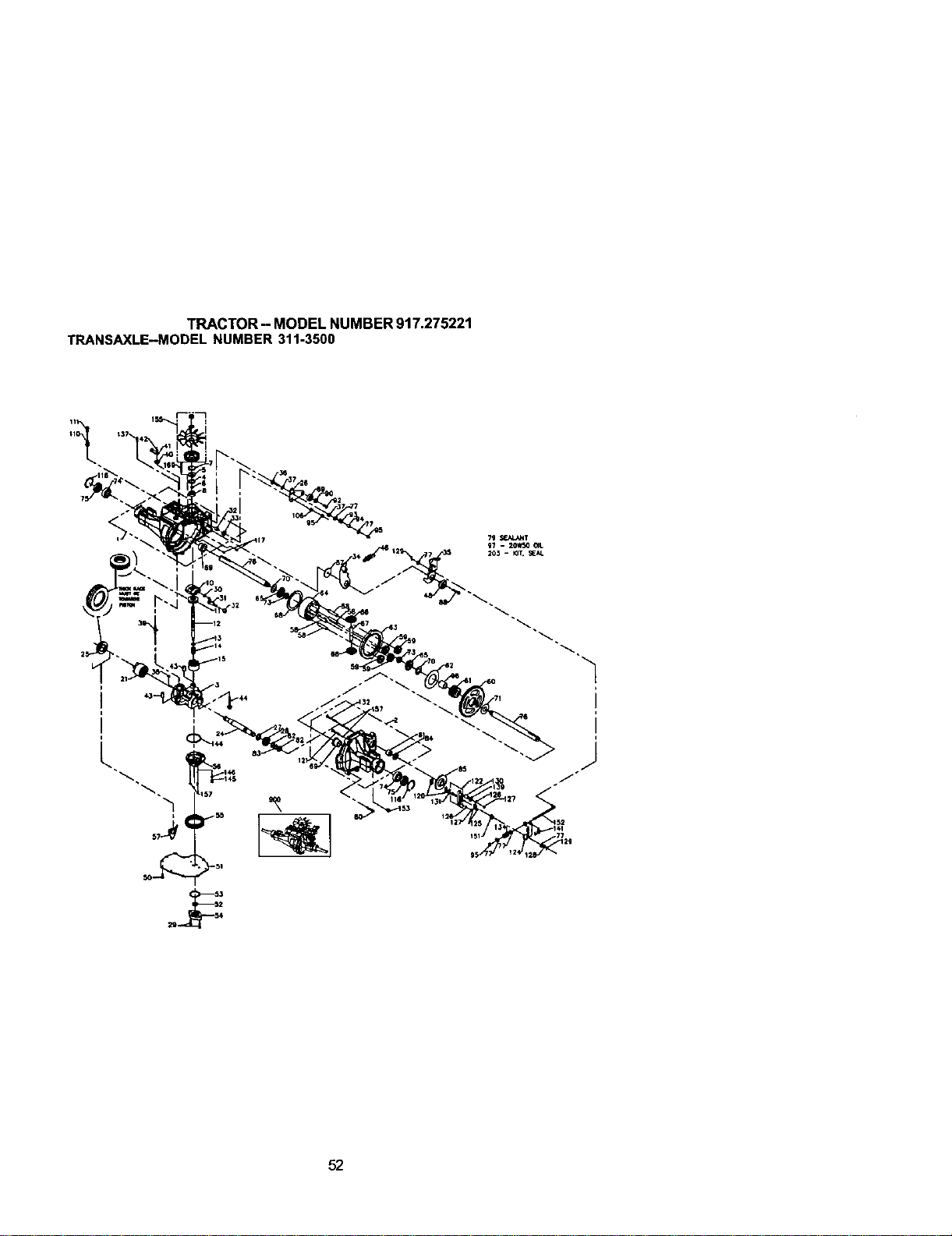
TRACTOR- MODELNUMBER917.275221
TRANSAXLE-MODELNUMBER311-3500
i
52

TRACTOR - MODEL NUMBER 917.275221
TRANSAXLE--MODELNUMBER311-3500
KEY PART KEY pART
NO. NO. DESCRIPTION NO. NO. OESCRIPllON
1 161122 Main Housing Assembly 74 169535 BallBrg 6205-1
2 178317 R.H. Housing Assembly 75 161157 Seal l"ld X 2.0472" X B.375"
3 169522 Center Section Assembly 76 161153 Shaft, Axle
4 161125 Spacer 77 142884 Washer
5 142932 Seal-Lip 79 178322 Gasket Mateda]
6 142928 Wire Retaining Ring 80 161159 Torx Head Screw, 5/16-18
7 142933 Retaining Ring 81 161160 Needle Beadng(Sce1412)
8 142934 BallBeadng 82 161161 Washe_2
9 169523 Cradle Beadng 83 161162 RetainingRing
10 169524 Vadable Swashplate 84 161163 UpSeal
11 150771 Thrust Beadng 30 X 52 X 13 (O.875i.D.X1.3o,D.X0.25
12 161126 Input Shal_ 85 161164 Brake Disk
13 142978 Block Thrust Washer 87 178323 Washer
14 142977 Arm-Trunnion 88 178324 Screw5/16-24
15 196050 10cc Cylinder Block Assembly 89 178325 Bearing
21 169525 21cc Cylinder Block Assembly 90 178326 Spacer
24 161127 Output (Motor) Shaft 91 169536 Oring. 0.070 X 0,239
25 169526 Thrust Bearing 42 X 68 X 16 92 178327 Screw
26 161128 ControlArm 93 142969 Spring, Fdclton Pack
27 161129 Spaosr 94 142980 Spacer, Friction Pack
28 161130 16t Pinion Gear 95 169537 Hex Lock Nut 5/16-24
29 169527 Capscrew, M6 X 1-22 96 169538 Sleeve Bearing
30 142941 BIct Guide 97 150798 Oil
31 161132 Trunnion Ann 106 161166 Spacer,Trunnion
32 161133 Trunnion Bushing 108 178328 Plug
33 142940 Lip Seal 110 142918 FitUng-O Ring Ass'y
34 178318 Arm Return 111 142917 Cap Vent Ass'y
35 178319 Arm Actuating 116 169539 Retaining Ring
36 169528 5/16-24 Stud 117 161168 Std Hdls Pin
37 142967 Puck, Fdction 120 142883 Puck, Brake
38 150787 Bypass Plate 121 169540 Rib Neck Bolt, 2"
39 169529 Bypass Actuator 122 178329 Brake Yoke
40 142945 LipSeal 124 178330 Arm, Brake
41 142952 Bypass Arm 125 142887 Pins, Brake
42 142953 Retaining Ring 126 161172 Lockwasher, 1/4"
43 142965 Pin 127 161173 Nut, 1/4-20
44 150797 Screw 128 142885 Nut, Caslte
48 178320 Puck 129 142886 Cotter Pin
50 178343 Screw-Self Tapping 130 161174 Spacer
51 169530 LowerCover 131 142882 Puck Plate
52 169531 GerotorAssembly 132 169544 Rib Neck Bolt, 3" 1
53 144581 O-Ring 134 178331 Spnng
54 161139 Gerotor Cover 136 178332 Spring Extension
55 178321 Filter 137 178333 Pin Spdng
56 169533 Charge Manifold 138 178334 Bolt Self Tapping
57 161142 Retainer, Motor Beadng 139 161176 Washer.
58 161143 Pin,Carrier 7/8od X 0,265id X 0.125 Thk
59 161144 15t Planet Gear 141 178335 Spring Brake
60 161145 7t Spur Gear 144 169545 O Ring, 2.664 Id X 0,070 Thk
61 161146 21t Sun Gear 145 169546 Spring,Relief
62 161147 Planet Thrust Plate 146 169547 Ball, 7/16
63 161148 511 Ring Gear 151 161181 Comp. Spdng, Brake Anti-Drag
64 161149 Planetary Carrier 152 178336 Brake PullRod
65 178511 Miter Gear, Oiff,(Splined) 153 142914 Plug, StraightThread
66 178512 Miter Gear, Diff, 155 178337 Kit Fan
67 161152 Shaft, Differential 157 169548 ScrewO-Ring
68 161163 Diff, Thrust Plate 180 169549 Manifold Kit
166_34 Flange Beadng 203 178338 Kit Seal
70 161154 Washe# 900 176057 Transaxle, complete
71 161155 Washer
73 161156 Hex Jam Nut, 5/8-16 NOTE: All component dimensions given in U.S, inches
1 inch = 25,4 mm
53
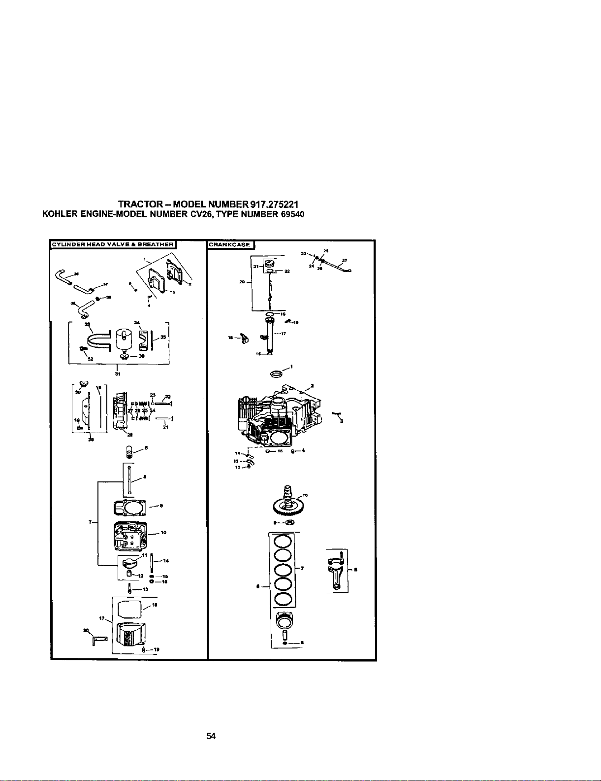
TRACTOR--MODELNUMBER917.275221
KOHLERENGINE-MODELNUMBERCV26,TYPENUMBER69540
CRANKCASE J
I--_E)
ll-- _7
Ou|
54
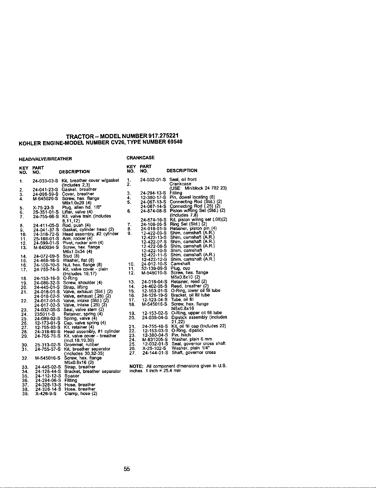
TRACTOR- MODELNUMBER917.275221
KOHLERENGINE-MODELNUMBERCV26,TYPENUMBER69540
HEADNALVE/BREATHER
CRANKCASE
KEY PART KEY PART
NO. NO, DESCRIPTION NO. NO. DESCRIPTION
1. 24-033-03-S Kit, breather cover w/gasket 1. 24-032-01-S Seal, oil front
(Includes 2,3) 2. Crankcase
2. 24-041-23-S Gasket, breather (USE: Miniblock 24 782 23)
3. 24-096-59-S Cover, breather 3. 24-294-13-S Fittin
4. M-645020-S Screw, hex flange 4. 12-380-17-S Pin o_owel locating 6
M6xl.0x20 (4) 5. 24-067-t3-S Connecflng Rod (Std. (2
5. X-75-23-S Plug, allen hd. 1/8" 24-067-14-S Connecting Rod .25 2)
6. 25-351-01-S Lifter, valve _4 6. 24-874-08-S Piston wiRing Set (Std.) (2)
7. 24-755-66-S Kit, valve train ncudes (Includes 7,8)
8,11,12) 24-874-16-S Kit, piston wiring set (.08)(2)
8. 24-411-05-S Rod, push 4) 7. 24-108-05-S Ring Set (Std.)(2
9. 24-041-37-S Gasket, cylinder head (2) 8. 24-018-01-S Retainer, piston pin (4)
10. 24-318-72-S Head assembly, #2 cylinder 9. 12-422-09-S
11. 25-186-01-S Arm, rocker(4) 12-422-13-S Shim, camshaft A.R.
12. 24-599-01-S Pivot, rocker arm (4) 12-422-07-S Shim, camshaft A.R.
13. M-640034-S Screw, hex flange 12-422-08-S Shim, camshaft A.R.
M6x10x34 (4) 12-422-10-S Shim, camshaft
14. 24-072-09-S Stud (8) 12-422-11-S Shim, camshaft A.R.)
15. 24-468-16-S Washer, fiat (8) 12-422o12-S Shim, camshaft A.R.
16. 24-100-10-S Nut, hex. flange 8 10. 24-012-10-S Camshaft
17. 24-755-74-S Kit, valve cover - plain 11. 52-139-09-S Plug, cup
Includes 16,17) 12. M-545010-S Screw, hex. flange
18 24-153-16-S O-Rng M5x0.8xl0 2)
19. 24-086-32-S Screw, shoulder (4) 13. 24-018-04-S Retaner, reed (2)
20. 24-445-01-S Strap, lifting 14. 24-402-05-S Reed, breather 2)
21. 24-016-01-S Valve. exhaust Std) (2) 15. 12-153-01-S O-Ring, lower oil fill tube
24-016-02-S Valve, exhaust (.25) (2) 16. 24-126-19-S Bracket, oil fill tube
22. 24-017-01-S Valve, intake Std. (2 17. 12-123-04-S Tube, oil fill
24-017-02-S Valve, ntake .25 2 18. M-545016-S Screw, hex. flange
23. 24-032-05-S Seal, valve stem (2) M5x0.8x16
24. 235011-S Retainer, spring (4) 19. 12-153-02-S O-Ring, upper oil fill tube
25. 24-089-02-S Spdng, valve (4) 20. 24-038-04-S Dipstick assembly (includes
26. 12-173-01-S Cap, valve spring (4) 21,22)
27. 12-755-03-S Kit, retainer (4) 21. 24-755-46-S Kit, oil fill cap (Includes 22)
28. 24-318-69-S Head assembly, #1 cylinder 22. 12-153-03-S O-Ring, dipstick
29. 24-755-76-S Kit, valve cover - breather 23. 12-380-04oS Pin, hitch
(IncL18,19,30) 24. M-631005-S Washer, plain 6 mm
30. 25-313-02-S Grommet, rubber 25. 12-032-01-S Seal, governor cross shaft
31. 24-755-57-S Kit, breather separator 26. X-25-102-S Washer, plain 1/4"
(Includes 30,32-35) 27. 24-144-01-S Shaft, governor cross
32. M-545016-S Screw, hex. flange
M5x0.gx16 (2)
33. 24-445-02-S Strap, breather NOTE: All component dimensions given in U.S.
34. 24-126-44-S Bracket, breather separator inches 1 inch = 25.4 mm
35. 24-112-12-S Spacer
36. 24-294-06-S Fitting
37. 24-326-13-S Hose, breather
38. 24-326-14-S Hose, breather
39. X-426-9-S Clamp, hose (2)
55
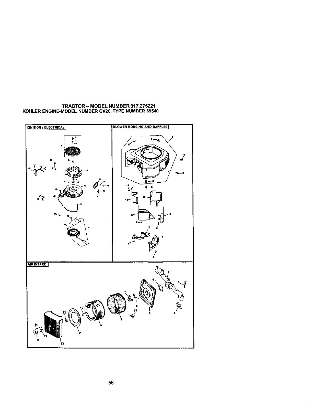
TRACTOR - MODEL NUMBER 917.275221
KOHLER ENGINE-MODEL NUMBER CV26, TYPE NUMBER 69540
IGNITION / ELECTRICAL I
BLOWER HOUSING AND BAFFLES I
|Iz
14_ _ 13_
lO u
/
S/|
I
AiR INTAKE J
13
56
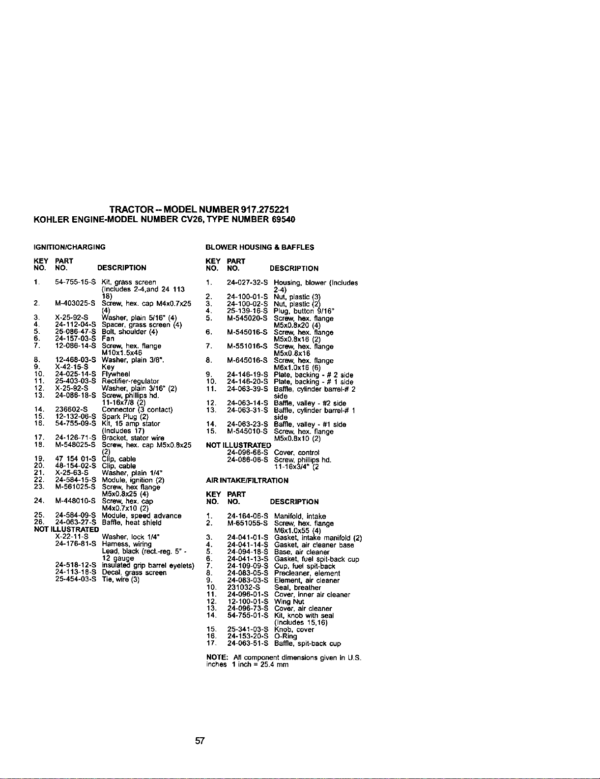
TRACTOR - MODEL NUMBER 917.275221
KOHLERENGINE-MODELNUMBERCV26,TYPE NUMBER69540
IGNITIONIBHARGING
BLOWER HOUSING & BAFFLES
KEY pART KEY PART
NO. NO. DESCRIPTION NO. NO. DESCRIPTION
1. 24-027-32-S Housing, blower (Includes
1. 54-755-15-S Kit, grass screen
_lncludes 2_,and 24 113 2-4)
18) 2. 24-100o01-S Nut, plastic (3
2. M-403025-S Screw, hex. cap M4x0,7x25 3. 24-1g0-02-S Nut plastic (2)
(4) 4. 25-13g-16-S Plug, button 9/16
5. M-545020-S Screw, hex. flange
3. X-25-92-S Washer, plain 5/16" (4)
4. 24-112-04-S Spacer, grass screen (4) M5xfl.8x20 (4)
5. 25-086÷47-S Bolt, shoulder (4) 6. M-545016-S Screw, hex. flange
6. 24-157÷03-S Fan M5xg.8x16 (2)
7. 12-086-14-S So'ew, hex. flange 7. M°551016-S Screw, hex. flange
M10x1.5x46 M5x0,8x16
8. 12-468-03-S Washer, plain 3/8". 8. M-645016-S Screw, hex. flange
9. X-42-15-S Key M6xl.gx16 (6)
10. 24-025-14-S Flywheel 9. 24-146-19°S Plate backing - # 2 side
11. 25°403-03-S Rectifier-regulator 10. 24-146-20-S Plate, backing - # 1 sde
12. X-25-92-S Washer, plain 3/16" (2) 11. 24-063-39-S Baffle, cylinder barrel-# 2
13. 24-086-16-S Screw, phillips hd. side
11-16x7/8 (27 12. 24-063-14-S Baffle, valley - #2 side
24-063-31-S Baffle, cylinder barrel-# 1
14. 236602-S Connector (3 contact) 13,
15. 12-132-06-S SparkPlug (2) side
16. 54-755-0g°S Kit, 16 amp starer 14. 24-063-23-S Ba_e, vatley - #1 side
Includes 17 15. M°545010-S Screw, hex. flange
17. 24°126-71-S Sracke, saorwre M5xO.8xlO (2)
18. M-548025°S Screw, hex. cap M5x0.Sx2.5 NOT ILLU_I"RATED
(2) 24-096-66-S Cover, control
19. 47 154 Of-S Grip, cable 24-086-06-S Screw, hillips hd.
20. 48-154-02-S Clip, cable 11-16x_}4" (2
21. X-25-63-S Washer, plain 1/4"
22. 24-584-15-S Module, ignition(2) /MRtNTAKEtFILTRATION
23. M-561025°S Screw, hex flange
M5xO.8x25 (4) KEY PART
24. M-448010-S Screw, hex. cap NO. Re. DESCRtPT_ON
M4xO.7xlO (2)
25. 24-584-09-S Module. speed advance 1. 24-164-06-S Manifold, intake
26. 24-063-27-S Baffle, heat shield 2. M-651055-S Screw, hex. fMoge
NOT ILLUSTRATED M6x1.0x55 (4
X-22-_1-S Washer, lock. 1/4" 3. 24-041-01-S Gasket. intake man fold (2)
24-176-81-S Harness. wiring 4. 24-041-14-S Gasket, air cleaner base
Lead, black (rect.-reg. 5" - 5. 24-094-18-S Base, air cleaner
12 auge 6. 24-041-13-S Gas_.et, fue_ s 't_>ack cup
24-518-12-S insulated ghp barrel eyeletS) 7. 24-109-09-S Cup, fuel spit-_a_ck
24-113-18-S Cecal, grass screen 8. 24-083-05-S Precleaner, element
25-454-03-S Tie, wire (3) 9. 24-083-03-S Element, air cleaner
10. 231032-S Seal, breather
11. 24-096-01-S Cover, inner air cleaner
12. 12-100-01-S Wing Nut
13. 24-096-73-S Cover, air cleaner
14. 54-755-gl-S Kit, knob with seat
(Includes 15,16)
15. 25-341-03-S Knob, cover
16. 24-153-20-S O-Ring
17. 24-063-51-S Baffle, spit-back cup
NOTE: All component dimensions given in U.S.
inches 1 inch = 25.4 mm
57
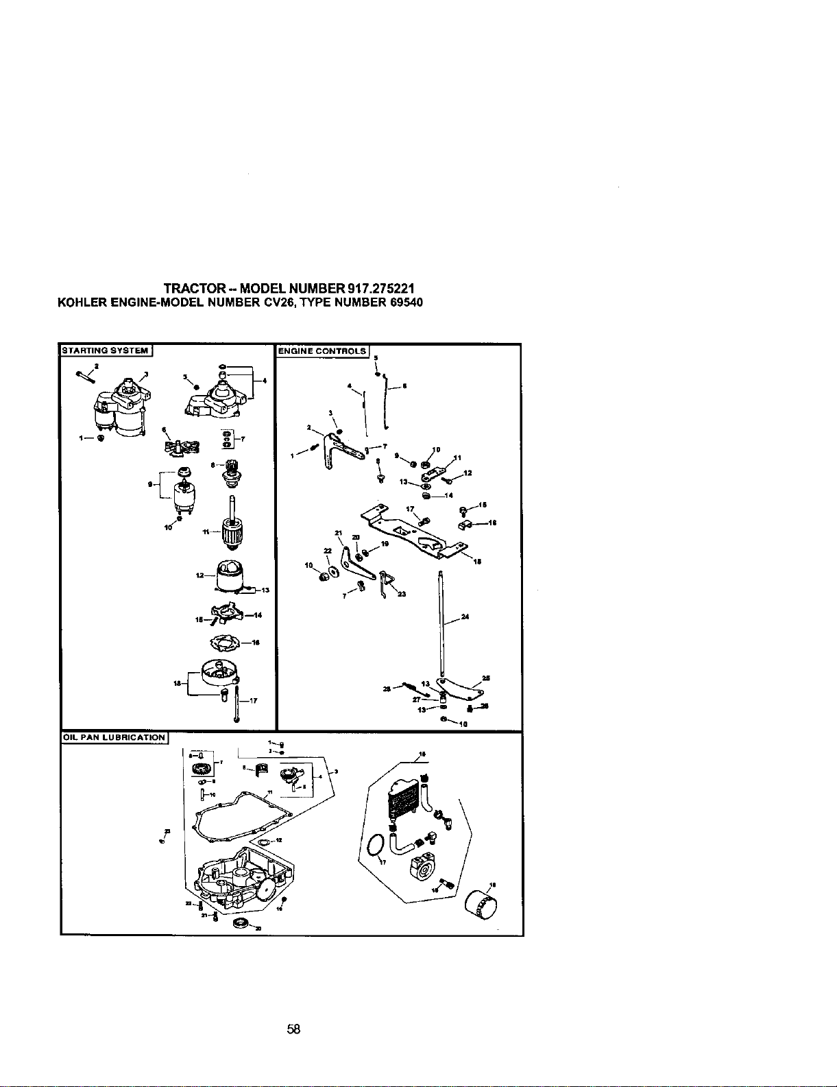
TRACTOR-- MODEL NUMBER 917.275221
KOHLERENGINE-MODELNUMBERCV26,TYPE NUMBER69540
STARTING SYSTEM ]
t8___ "-14
O--16
OIL PAN LUBRICATION I
Z
ENGINE CONTROLS !
$
t
I
3
j_
13 (
13_'_D
6_10
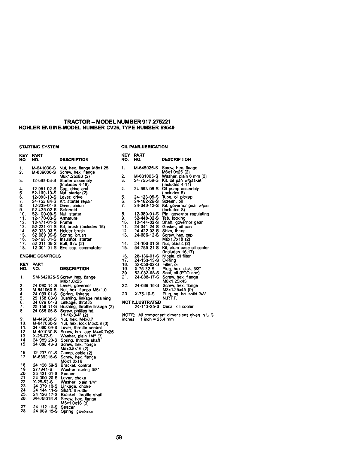
TRACTOR - MODEL NUMBER 917.275221
KOHLERENGINE-MODELNUMBERCV26,TYPE NUMBER69540
STARTING SYSTEM
OIL PANILUBRICATION
KEY PART KEY PART
NO. NO, DESCRIPTION NO, NO, DESCRIPTION
1. M-841080-S Nut, hex. flange MSx1,25
2. M-S3gOSO-S Screw. hex. flange
MSxl.25xS0 2)
3. 12-098-g3-s Starter assemb y
(Includes 4o18)
4. 12-081-02-S Cap, drive end
5. 52-100-1g-S Nut. starter (2)
6, 12-090-10-S Lever, drive
7, 24-755 84-S Kit, starter repair
8, 12.23g-61-S Bdve, pinion
9. 52-435-g2-s Solenoid
10. 52-100-09-S Nut. starter
11. 12-170-g3-s Armature
12. 12.471-gl-S Frame
13. 52-221-01-S Kit, brush Includes 15)
14. 52 323 fl3-S Hoder brush
15. 52 089 0g-s Spring, brush
16. 52-168 01-S Insulator, starter
17. 52 211 05-S Bolt, thru (2)
18. 12o301-gl-S End cap, commutator
ENGINE CONTROLS
KEY PART
NO. NO. DESCRIPTION
1. SM-642025-SScrew, hex. flange
M6x1.0x25
2. 24 090 14-S Lever, governor
3. M.641060-S Nut, hex. flange M6xl.g
4. 24 089 01-S Spring, linkage
5. 25 158 08-S Bushing. llnkagee retaining
6. 24 679 _4-S Lin_age throttta
7. 25 158 11-S Bushing, throttle linkage (2)
8. 24 086 06-S Screw, plhillips hal.
11-16x3/4" (2)
9. M-446930-S Nut, hex. M4x0.7
1O. M-64796g-S Nut, hex. _ck M5xg.fi _3_
11. 24 090 09-S Lever, throttle control
12. M-401030-S Screw, he)(. cap M4x0.7x25
13. X-25-72-S Washer, plain 1/4" (3
14. 24 089 20-S Spring, throttle shaft
15. 24 g86 43-S Screw, he.x. flange
M5x0.8xlfl (2)
16. 12 237 01-S Clamp, cable (2)
17. M-639016-S Screw, hex. flange
M6xl.0x16
18. 24 126 59-S Bracket. control
19. 277341-S Washer, spring 3/8"
20. 25 431 Ol-S Spacer
21. 24 090 20-S Lever, choke
22. X-25-52-S Washer, plain 1/4"
23. 24 079 lg-S Linkage, choke
24. 24 144 11-S Shaft, throttle
25. 24 126 17-S Bracket, throttle shaft
26. M-645016-S Screw, hex. flange
M6xl.gx16 (3)
27. 24 112 lg-S Spacer
28. 24 059 15-S Spnng, governor
1. M-64flg25-S Screw, hex. flange
M6x1.Ox25 (2)
2. M-631g05-S Washer, plain 6 mm (2)
3. 24-755-59-S Kit, oll pan w/gasket
(Includes 4-1
1)
4, 24-393-g8-s Oil pump assembly
(Includes 5)
5. 24-123-g5-s Tube, oil pickup
6. 24-152-26-S Screen, oil
7. 24-043-12-S Kit, governor gear w/pin
(Includes 8)
8. 12-38g-01-S Pin, governor regulating
9. 52-445-02-S Tab, locking
10. 12-144-02-S Shaft, governor gear
11. 24-041-24-S Gasket, oil pan
12. 24-422-03-S Shim, thrust
13, 24-086-12-S Screw, hex. cap
MSx1.7x15 2)
14. 24-100-01-S Nut, plastic 2)
15. 54 755 21-S Kit, alum base oil cooler
(Includes 16,17)
16. 28-136-01-S Nipple, oil filter
17. 24-153-13-S O-Ring
18. 52-0f10-02-S Filter, oil
19. X-75-32-S Plug, hex. ctsk. 3/8"
20. 52-g32-g8-s Seal, oil (PTO end)
21. 24-0fl6-17-S Screw, hex. flange
Mfix1.25x45
22. 24-086-16-S Screw, hex. flange
Mflxl.25x45 (9)
23. X-75-10-S Plug, sq. hd. solid 3/8"
N.RT.F.
NOT tLLLISTRATED
24-113-25-S Decal, oil cooler
NOTE: All componentdimensionsgivenin U,S,
inches 1 inch = 25.4 mm
59
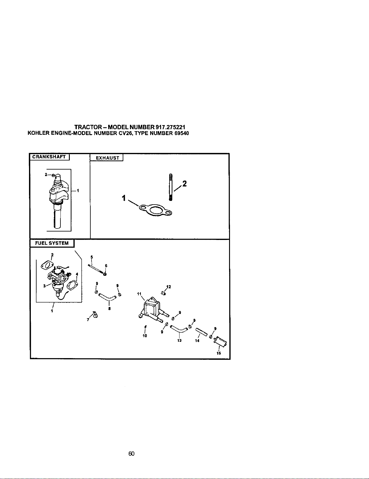
TRACTOR - MODEL NUMBER 917.275221
KOHLERENGINE-MODELNUMBERCV26,TYPE NUMBER69540
CRANKSHAFT I
2-
ml
EXHAUST J
FUELSYSTEM J
4
/
1
5
6
9 9
8
/g
7
/.9
/9
13 14
15
6O
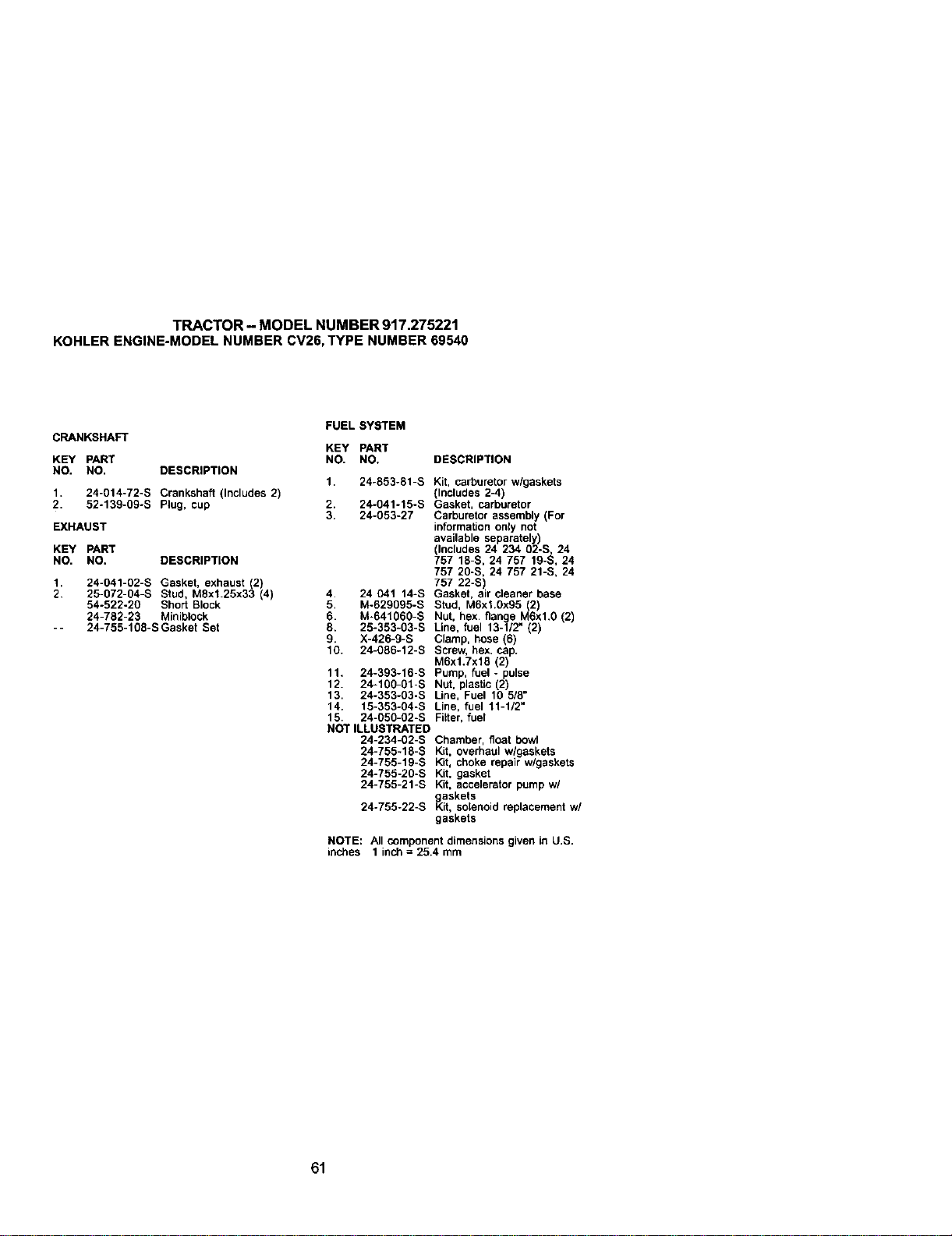
TRACTOR- MODELNUMBER917.275221
KOHLERENGINE-MODELNUMBERCV26,TYPENUMBER69540
CRANKSHAFT
KEY PART
NO. NO. DESCRIPTION
1. 24-014-72-S Crankshaft (Includes 2)
2. 52-139-09-S Plug, cup
EXHAUST
KEY PART
NO. NO. DESCRIPTION
1. 24-041-02-S Gasket, exhaust (2)
2, 25-072-04-S Stud, M8xl.25x33 (4)
54-522-20 Short Block
24-782-23 Miniblock
-- 24-755-108-S Gasket Set
FUEL SYSTEM
KEY PART
NO. NO. DESCRIPTION
1. 24-853-81-S Kit, carburetor w/gaskets
(Includes 2-4)
2. 24-041-15-S Gasket, carburetor
3. 24-053-27 Carburetor assembly (For
information only not
available separately)
(Includes 24 234 O2-S, 24
757 18-S, 24 757 19-S, 24
757 2g-s, 24 757 21-S, 24
757 22-S
4. 24 041 14-S Gasket. a r c eaner base
5. M-629095-S Stud, M6xt.gx95 (2)
6. M-64106O-S Nut, hex. flange M6xl.g (2)
8. 25-353-03-S Line, fuel 13-1/2" (2)
9. X-426-9-S Clamp, hose (6)
10. 24-086-12-S Screw, hex. cap.
M6x1.7x18 (2)
11. 24-393-16-S Pump, fuel - pulse
12. 24-10g-o1-s Nut, plastic (2)
13. 24-353-g3-s Line, Fuel 10 518"
14. 15-3f13-g4-s Line, fuel 11-1/2"
15. 24-050-02-S Filter, fuel
NOT ILLUSTRATED
24-234-02-S Chamber, float bowl
24-755-18-S Kit, overhaul wlgaskets
24-755-19-S Kit, choke repair w/gaskets
24-755-20-S Kit, gasket
24-755-21-S Kit, accelerator pump wl
gaskets
24-755-22-S Kit, solenoid replacement w/
gaskets
NOTE: All componentdimensions given in U.S.
inches 1 inch = 25.4 mm
61

62
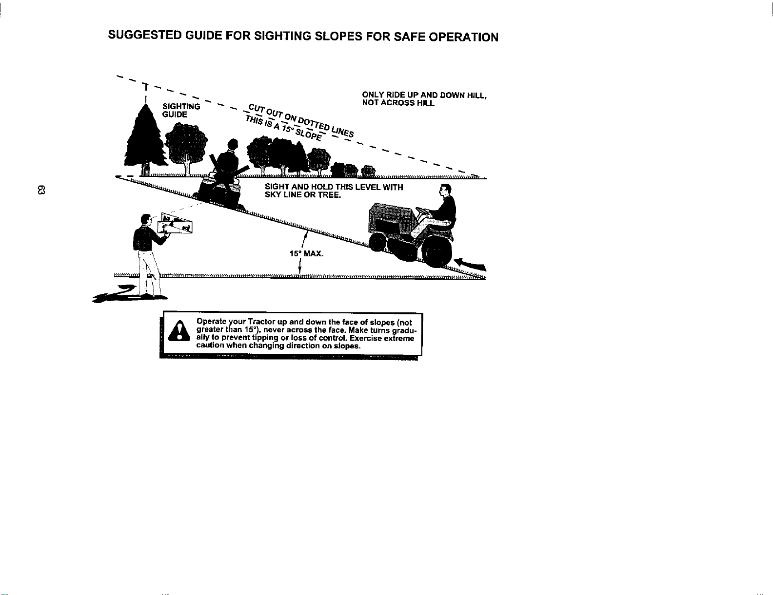
SUGGESTED GUIDE FOR SIGHTING SLOPES FOR SAFE OPERATION
ONLY RIDE UP AND DOWN HILL,
NOTACROSS HILL
I_ Operate your Tractor up and down the face of slopes (not
greater than 15°), never across the face. Make turns gradu- I
ally to prevent tipping or loss of control. Exercise extreme |
caution when changing direction on slopes. |
I

For repair of major brand appliances in your own home...
no matter who made it, no matter who sold it!
1-800-4-MY-HOME sMAnytime, day or night
(1-800-469-4663)
www.sears.com
To bring inproductssuch as vacuums,
lawn equipment and electronicsforrepair,call for
the locationof your nearest Sears Parts & Repair Center.
1 800 488 1222 _i ight
" " " me, day or n
www.sears.com ii_il;
For the replacement parts, accessories and owner's manuals
that you need to do-it-yourself, call Sears PartsDirectSM!
1-800-366-PART 6 a.m. - 11 p,m. CST,
(1-800-366-7278) 7 days a week
www, sears.com/partsdlrect _;,i.......
......................................................................................................................................................................................_'_
Topurchase or inquire about a Sears Service Agreement:
1-800-827-6655
7 a.m. - 5 p.m. CST, Mort. - Sat.
; _!i!
Para pedir servicio de reparacibn a domicilio, AU Canada pour service en franc_ais:
y para ordenar piezas con entrega a domicilio: 1.877.LE.FOYER s"
(1-877-533-6937)
1.888.SU.HOGAR _"
(1-888-784-6427)
........ [ SEARS|
,_ '_i_ t HomeCentral ®
J
© Sears, Roebuck and Co.
® Registered Trademark / n_ Trademark of Sears, Roebuck and Co.
® Marca Registrada / 1" Marca de Ft*brica de Sears, Roebuck and CO.
178309 02.07.01 RH Printed in U.S.A.


