Loading ...
Loading ...
3
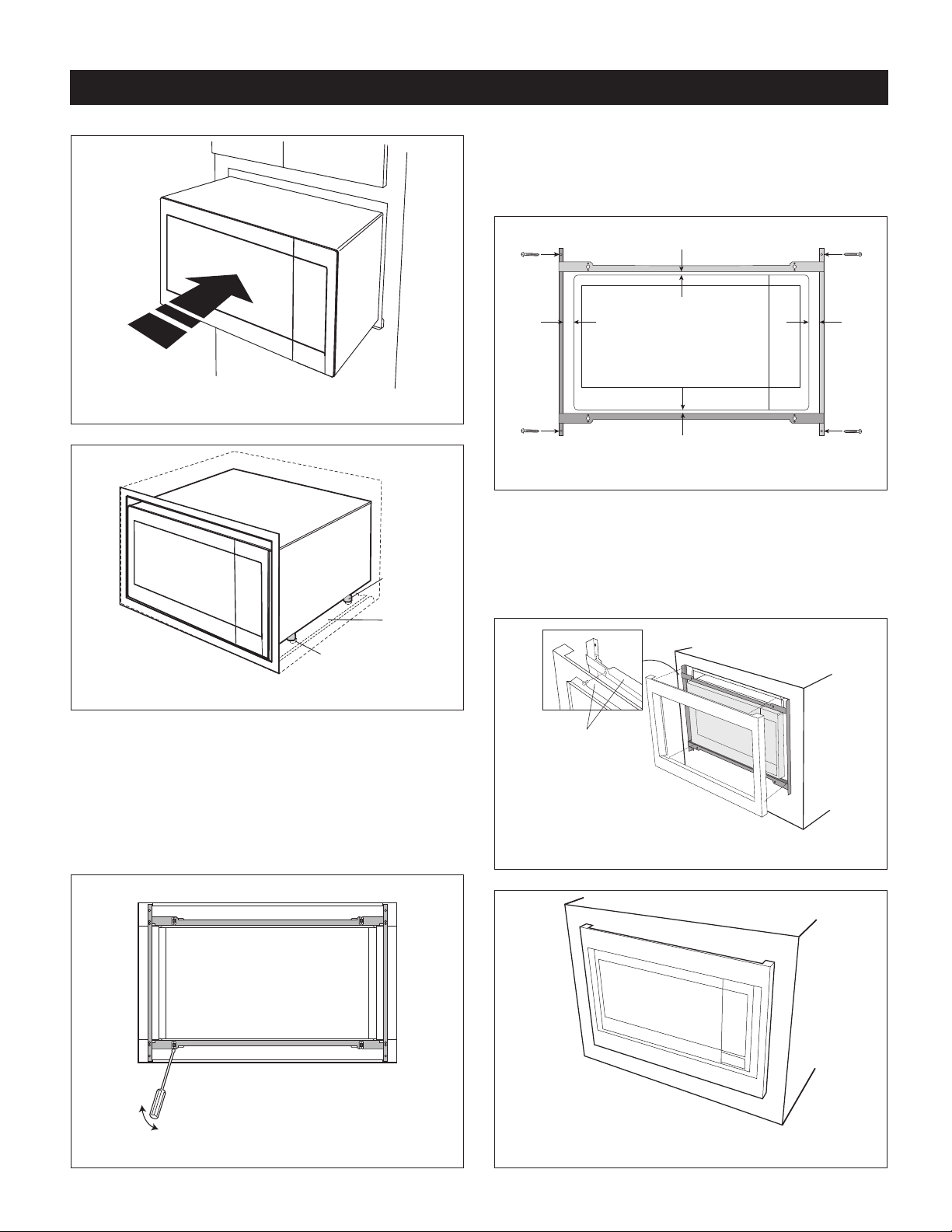
FIGURE 4
Exhaust
duct
assembly
Foot
Duct recess
FIGURE 5
3. DISASSEMBLY: The FRONT FRAME and BACK FRAME
come pre-assembled with ball studs engaged in the
receivers. Separate the FRONT FRAME from the BACK
FRAME. Place the assembly facedown onto a protected
surface. At the location of the ball stud, insert a athead
screwdriver between the FRONT FRAME and the BACK
FRAME and gently pry up to disengage the ball stud from
the receiver. Repeat for each corner. See Figure 6.
FIGURE 6
STANDARD INSTALLATION INSTRUCTIONS
4. BACK FRAME INSTALLATION: Position back frame with
equal space top to bottom, side to side. Mark for 4 holes,
center punch and pre-drill the cabinet with
1
/16" drill bit.
Secure frame with 4 SCREWS E. See Figure 7.
Equal gap top, bottom
Equal gap
side to side
Mounting holes
Mounting holes
Mounting holes
Mounting holes
Screw E
Screw E
Screw E
Screw E
FIGURE 7
5. FRONT FRAME INSTALLATION: Place the FRONT
FRAME onto the BACK FRAME and align ball studs
and receivers. Secure the FRONT FRAME to the BACK
FRAME by rmly pushing the front frame onto the
back frame, engaging the 4 snap attachments. See
Figures 8-9.
Snap
attachment
FIGURE 8
FIGURE 9
Loading ...
Loading ...
Loading ...