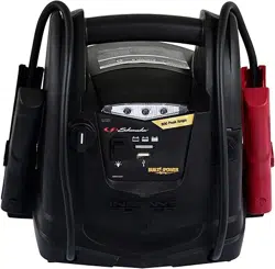
When connected to a battery, the digital display can be used to indicate the battery’s voltage. When not connected to a battery, the digital display can be used to indicate the percent of charge or the voltage of the jump starter’s internal battery.
To check the internal battery’s charge status, make sure the rotary switch is in the OFF position, then press the display button on the front of the jump starter. The digital display will show the battery’s percent of charge. A fully charged battery will read 100%. Charge the internal battery if the display shows it is under 100%.
NOTE: The internal battery’s percent of charge is most accurate when the jump starter has been disconnected from all devices and charging sources for a few hours.
To check the voltage level of the jump starter’s internal battery, make sure the clips are attached to their plastic storage holders and not touching each other, and then turn the rotary switch to the 12V position (12V or 24V position on DSR115). The display will indicate the battery’s voltage.
To check the voltage level of the vehicle’s battery, make sure the switch in the OFF position, then connect the clips to the vehicle’s battery. The display will indicate the battery’s voltage
Charger LED Indicators
POWER (green) LED lit: The charger is connected to AC power
CHARGING STATUS LED (green) pulsing slowly: The charger is charging the jump starter’s internal battery, or the battery is fully charged and the charger is in Maintain mode.
CHARGING STATUS LED (yellow/orange) flashing rapidly: The charger has detected a problem with the battery. See Troubleshooting for more information.
BAD BATTERY (red) LED lit: The charger has detected a problem with the battery. SeeTroubleshooting for more information.
CHARGING THE INTERNAL BATTERY OF THE JUMP STARTER
Grounding and AC Power Cord Connections
IMPORTANT: Only use the charger that was included with the jump starter to charge the internal battery of the jump starter. Using a different charger could result in personal injury or property damage.
WARNING! RISK OF ELECTRIC SHOCK OR FIRE. This battery charger is for use on a nominal 120V circuit. The plug must be plugged into an outlet that is properly installed in accordance with all local codes and ordinances. The plug pins must fit the receptacle (outlet). Do not use with an ungrounded system.
DANGER. Never alter the AC cord or plug provided – if it does not fit the outlet, have a proper outlet installed by a qualified electrician. An improper connection can result in a risk of an electric shock or electrocution.
An extension cord should not be used unless absolutely necessary. Use of an improper extension cord could result in a risk of fire and electric shock. If an extension cord must be used, make sure:
• That the pins on the plug of the extension cord are the same number, size and shape as those of the plug on the charger.
• That the extension cord is properly wired and in good electrical condition.
• That the wire size is large enough for the AC ampere rating of the charger, as specified:
*AWG-American Wire Gauge
Charging the Jump Starter with included Charger
1. Make sure the charger and jump starter are placed on a dry, nonflammable surface. To charge the jump starter, plug the charger into the charging port on the front of the jump starter.
2. Confirm the AC outlet voltage matches the input voltage of the charger.
3. Connect the charger to the AC wall outlet and confirm that the green POWER LED on the charger turns on.
4. Check that the green CHARGING STATUS LED on the charger is pulsing slowly, to indicate that charge process has started. To see the status of the charge, check the percentage shown on the jump starter display.
5. When the jump starter display shows 100 (%), the internal battery is fully charged and the jump starter is ready to use. Complete charging may take up to 24 hours.
NOTE: The green CHARGING STATUS LED will remain pulsing after the display shows 100%, as the charger automatically goes into Maintain mode and maintains the battery at full charge without damaging it.
6. After the charge is complete, disconnect the charger from the AC outlet, then disconnect the charger from jump starter.
Charger Modes
Automatic charging mode
When an automatic charge is performed, the charger switches to maintain mode automatically after the battery is charged.
Aborted Charge
If charging cannot be completed normally, charging will abort. When charging aborts, the charger’s output is shut off. The BAD BATTERY (red) LED will light. Do not continue attempting to charge the battery. Check the battery and replace, if necessary.
Desulfation Mode
Desulfation could take 8 to 10 hours. If desulfation fails, charging will abort. The red BAD BATTERY LED will light and the yellow/orange CHARGING STATUS LED will flash.
Completion of Charge
When the internal battery is fully charged, the jump starter’s display will show “100”.
Maintain Mode (Float Mode Monitoring)
When the internal battery is fully charged and the jump starter display shows “100”, the charger has started maintain mode. In this mode, the charger keeps the battery fully charged by delivering a small current when necessary. If the charger has to provide its maximum maintain current for a continuous 12 hour period, it will go into abort mode (see Aborted Charge). This is usually an indication of a bad battery; have the jump starter checked.
Charging the Internal Battery While Driving
You may also charge the internal battery while driving, using a male-to-male charger cable (part number 94500109 – sold separately).
IMPORTANT: DO NOT CHARGE THE INTERNAL BATTERY FOR MORE THAN 30 MINUTES OR LEAVE THE BATTERY UNATTENDED. IT COULD EXPLODE, CAUSING PROPERTY DAMAGE OR PERSONAL INJURY.
1. Make sure the car is running.
2. Insert one end of the accessory cable into the 12V DC power outlet.
3. Insert the other end of the accessory cable into the vehicle’s accessory outlet (lighter socket).
NOTE: Using this method to charge the battery overrides the maintain mode and the battery can be overcharged.
4. Monitor the progress of the charge by pressing the Percentage of Charge button on the front of the unit. Do not leave the battery unattended or it could explode, causing property damage and personal injury. When the battery is fully charged, disconnect the accessory cable from the jump starter, and then from the lighter socket of the vehicle.
NOTE: Completely disconnect the charger cable when the engine is not running.
OPERATING INSTRUCTIONS
Jump Starting a Vehicle Engine
IMPORTANT: Using the jump starter without a battery installed in the vehicle will damage the vehicle’s electrical system.
IMPORTANT: Do not use the jump starter while charging its internal battery.
1. Turn the vehicle’s ignition OFF before making cable connections.
2. Make sure the rotary switch on the front of the jump starter is in the OFF position. Connect the jump starter to the battery, following the precautions listed in section 3.
WARNING! RISK OF EXPLOSION. If you have connected the clips backward, an audio alarm will sound. DO NOT turn the rotary switch to the 12V (12V or 24V for model DSR115) position. This could cause serious damage to the jump starter or the vehicle. Reverse the connections and the audio alarm will stop.
3. If no audio alarm sounds, turn the rotary switch to the 12V position (12V or 24V position for model DSR115). The clips are now powered.
4. Crank the engine. If the engine does not start within 3-8 seconds, stop cranking and wait at least 1 minute before attempting to start the vehicle again. (This permits the battery to cool down.)
5. After the engine starts, turn the rotary switch to the OFF position. Disconnect the black clip (-), then the red clip (+) in that order, and clip them back onto the jump starter storage holders.
6. Recharge the jump starter as soon as possible after use.
NOTE: If the cables are connected to a 24 volt system when the switch is in the 12 volt position, the audio alarm will sound continuously. TURN OFF the jump starter immediately or internal battery damage could occur.
NOTE: If the switch is in the 12V or 24V position or the jump starter is connected to a battery for more than five minutes, four beeps will sound. This is a reminder to turn the jump starter off and/or disconnect it from the vehicle’s battery when not in use.
WARNING! RISK OF EXPLOSION. To prevent sparking, NEVER allow the clips to touch together or to contact the same piece of metal. Never attempt to jump start a frozen battery.
Powering A 12V DC Device:
The jump starter is a power source for all 12V DC accessories that are equipped with a 12V accessory plug. Use it for power outages and fishing or camping trips. Estimated usage time is listed in the following chart.
1. Make sure the device to be powered is OFF before inserting a 12V DC accessory plug into the 12V DC socket.
2. Ensure the battery clips are securely clipped on the storage holders.
3. Open the protective cover of the 12V DC power outlet on the front of the jump starter.
4. Plug the 12V DC device into the 12V DC power outlet, and turn on the 12V DC device (if required).
5. If the 12V DC device draws more than 15A or has a short circuit, the internal circuit breaker of the jump starter will trip and disconnect the power to the device. Disconnect the 12V DC device. The breaker will automatically reset a short time after an overload is disconnected.
6. Recharge immediately after unplugging the 12V DC device.
12V DC ESTIMATED RUN-TIMES
NOTE: Estimated run-times. Actual time may vary. Times are based on the internal battery being fully charged.
USING THE USB PORT
The USB port provides up to 2.1A at 5V DC.
Ensure the battery clips are securely clipped on the storage holders.
Press the USB button on the front of the unit.
Plug the device into the USB port on the front of the unit.
Turn the USB device on.
Reverse these steps when finished using the USB port.
Charge the jump starter as soon as possible after using the USB port.
MAINTENANCE INSTRUCTIONS
After use and before performing maintenance, unplug and disconnect the jump starter.
Use a dry cloth to wipe all battery corrosion and other dirt or oil from the battery clips, cords and the jump starter case.
Ensure that all of the jump starter components are in place and in good working condition.
All servicing should be performed by qualified service personnel.
MOVING AND STORAGE INSTRUCTIONS
1.Store inside, in a cool, dry place.
2. Do not store the clips on the handle, clipped together, on or around metal, or clipped to cables. The clips on the jump starter are live when the switch is in the ON position and will produce arcing or sparking if they come in contact with each other. To prevent accidental arcing, always place the switch in the OFF position and keep the clips on the storage holders when not using it to jump start a vehicle.
3. If the jump starter is moved around the shop or transported to another location, take care to avoid/prevent damage to the cords, clips and jump starter. Failure to do so could result in personal injury or property damage. IMPORTANT: Do not use and/or store the jump starter in or on any area or surface where damage could occur if the internal battery should unexpectedly leak acid.
4. IMPORTANT:
• CHARGE IMMEDIATELY AFTER PURCHASE
• KEEP FULLY CHARGED
Charge the jump starter’s internal battery immediately after purchase, after every use and every 30 days.
All batteries are affected by temperature. The ideal storage temperature is at 70°F. The internal battery will gradually self-discharge (lose power) over time, especially in warm environments. Leaving the battery in a discharged state may result in permanent battery damage. To ensure satisfactory performance and avoid permanent damage, charge the internal battery every month.
TROUBLESHOOTING
Jump Starter
PROBLEM
POSSIBLE CAUSE
SOLUTION
The jump starter won’t jump start my car.
Clamps are not making a good connection to the battery.
Check for poor connection to battery and frame. Make sure connection points are clean.
The jump starter’s battery is not charged.
Check the battery charge status by pressing the Display button on the front of the unit. The display will show the percentage of charge.
The vehicle’s battery is defective.
Have the battery checked.
The jump starter won’t power my 12V device.
The 12V device is not turned on.
Turn on the 12V device.
The jump starter’s battery is not charged.
Check the battery charge status by pressing the Display button on the front of the unit. The display will show the percentage of charge.
The 12V device draws more than 15A or has a short circuit.
Disconnect the 12V device. The internal breaker will automatically reset after a minute or two. Try using the 12V device again.
The battery in the jump starter won’t hold a charge.
The battery is bad (will not accept a charge).
Replace the battery.
The jump starter’s alarm is on.
Connections are reversed.
Disconnect the jump starter and reverse the clamps.
Charger
PROBLEM
REASON
SOLUTION
The green POWER LED does not light when charger is properly connected
AC outlet is dead.
Check for open fuse or circuit breaker supplying AC outlet.
Poor electrical connection.
Check power cord and extension cord for a loose fitting plug.
The red BAD BATTERY LED is lit.
The battery is sulfated.
The charger is in desulfation mode. Continue charging for several hours. If not successful, have the battery checked.
Lack of progress is detected and battery voltage is below 14.2V.
The battery may be overheated. If so, allow the battery to cool. The battery may be too large or have a short circuit. Have battery checked or replaced.
The battery’s initial voltage is below 12.2V and the total input is less than 1.5 Ah.
The battery capacity is too low, or the battery is too old. Have it checked or replaced.
The battery voltage drops below 12.2V during Maintain Mode
The battery won’t hold a charge. May be caused by a drain on the battery or the battery could be bad. Make sure there are no loads on the battery. If there are remove them. If there are none, have the battery checked or replaced.
The red BAD BATTERY LED is lit and the yellow/orange CHARGING STATUS LED is flashing rapidly
The battery voltage is still below 10V after 2 hours of charging. (or)
In maintain mode, the output current is more than 1.5A for 12 hours.
The battery may be defective. Make sure there are no loads on the battery. If there are, remove them. If there are none, have the battery checked or replaced.
Desulfation was unsuccessful.
The battery may be defective. Have battery checked or replaced.


 POWER LED does not light when charger is properly connected
 BAD BATTERY LED is lit.
 CHARGING STATUS LED is flashing rapidly