
1
PRONGK1 / PROLPK1 Conversion Kit
for 30” / 36” / 42” / 54” Outdoor Grills
Power Burner Accessory
Side Burner Accessory
Installation
GUIDE
2
IMPORTANT: PLEASE READ AND FOLLOW
1. Before beginning, please read these instructions completely and carefully.
2. Do not remove permanently a xed labels, warnings, or plates from
product. This may void the warranty.
3. Please observe all local and national codes and ordinances.
CAUTION: Before proceeding with the conversion, shut o the gas
supply to the appliance prior to disconnecting the electrical
power.
This conversion kit shall be installed by a
quali ed service agency in accordance with the
manufacturer’s instructions and all applicable
codes and requirements of the authority having
jurisdiction. If the information in these instructions
is not followed exactly, a re, explosion or
production of carbon monoxide may result
causing property damage, personal injury or loss
of life. The quali ed service agency is responsible
for the proper installation of this kit. The
installation is not proper and complete until the
operation of the converted appliance is checked
as speci ed in the manufacturer’s instructions
supplied with the kit.
WARNING
GAS CONVERSION
To convert a grill or accessory burners from natural to LP/Propane gas or
LP/Propane to natural, you must use the conversion kit supplied by the
manufacturer. When converting to Natural Gas, use the PRONGK1 kit for
30”/36” / 42”/54” Grills, Power Burner and Side Burner models. When
converting to LP/Propane, use the PROLPK1 kit for 30”/36” / 42”/54” Grills,
Power Burner and Side Burner models. Conversions should only be done by
an authorized service technician.
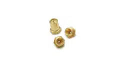
PRONGK1 Conversion Kit Part List
(1) Elbow 1/2 NPT, 90 degree Pipe Elbow
(1) #41S Ori ce, Main Burner 36” Model
(2) #44S Ori ce, Sear Burner 36” Model
(2) #50 Ori ce, IR Rotis 30”/36”/54” Models
(2) #68 Smoker Ori ce
(3) #41L, 1.375 Ori ce, Main Burner 30”/42”/54” Models
(1) #42S Ori ce, Sear Burner 30”/42”/54” Models
(1) 4/11 Regulator
(2) #185 Side Burner Ori ce
(1) #50L Ori ce, Inner Power Burner
(1) #35L Ori ce, Outer Power Burner
(1) Valve Valve, Main Burner, Red Spring
(1) 068907-000 Conversion Kit Instructions
(1) PF030427 Conversion Label
(1) 071523-000 Red Natural Gas Label
(1) #48 Ori ce, #48
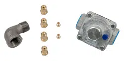
PROLPK1 Conversion Kit Part List
(1) Elbow 3/8” Flare to 1/2” FIP Pipe Elbow
(4) #53 Ori ce, Main Burner 36” Model
(1) #55 Ori ce, Sear Burner 36” Model
(2) #57 Ori ce, IR Rotis 30”/36”/54” Models
(2) #77 Ori ce, Smoker
(3) #53L, 1.375 Ori ce, Main Burner 30”/42”/54” Models
(2) #54 Ori ce, Sear Burner 30”/42”/54” Models
(1) 2-stage Regulator w/Hose
(2) #115 Side Burner Ori ce
(1) #57L Ori ce, Inner Power Burner
(1) #50L Ori ce, Outer Power Burner
(1) Valve Valve, Main Burner, Red Spring
(1) 068907-000 Conversion Kit Instructions
(1) PF030427 Conversion Label
(1) 071522-000 Yellow LP Gas Label
(1) #56S Ori ce, #56S
• 1 ¼” open end wrench or large channel locks (removing / installing
NG regulator)
• Phillips screwdriver (removing installing rear panel / adjusting air
shutters)
• ½” deep socket and ratchet (removing / installing gas ori ces on
burner valves)
• ½” open end wrench (removing / installing rotisserie burner
ori ce)
• 7/16” open end wrench or socket (removing / installing manifold
pipe)
• 3/8” socket (to remove the heat shield)
• 3/32” blade slot screwdriver - 3” long shaft (adjusting burner valves
to obtain proper minimum ame)
• 5/8” open end wrench (removing / installing LP regulator & hose
to are tting)
• Pipe wrench (removing / installing the LP – brass 90 degree ½” x
3/8” are elbow and NG – 90 degree street elbow connection at
manifold)
• Pipe dope, yellow Te on gas tape, etc (sealing gas connec tions)
Tools Needed
*NOTE: All parts in the kit may not be used depending on model being converted
3
*Important note for 30”/42”/54” Grills:
The main burner and power burner on the
30”/42”/54” grills require the long ori ce.
These ori ces are 1.375” in length. Failure to
use the longer ori ce on these models could
result in a serious re.
** 41L Long 1.375” in Length
** 53L Long 1.375” in Length
** 50L Long 1.375” in Length
** 57L Long 1.375” in Length
** 35L Long 1.375” in Length
GAS PLUMBING REQUIREMENTS
• A pressure regulator must be installed on all gas equipment. All local codes require that a pressure regulator be installed. Removing or failing
to install the pressure regulator can result in re and serious bodily harm.
• An installer supplied gas shut-o valve must be installed in an easily accessible location for all hardplumbed natural gas and liquid propane
applications.
• In order for a the grill to perform properly, you must have adequate gas plumbing. Please see the guidelines below to help ensure that you
have the appropriate gas plumbing with respect to gas pipe diameter, length of pipe run and the grills BTU requirements.
IMPORTANT: PLEASE READ AND FOLLOW
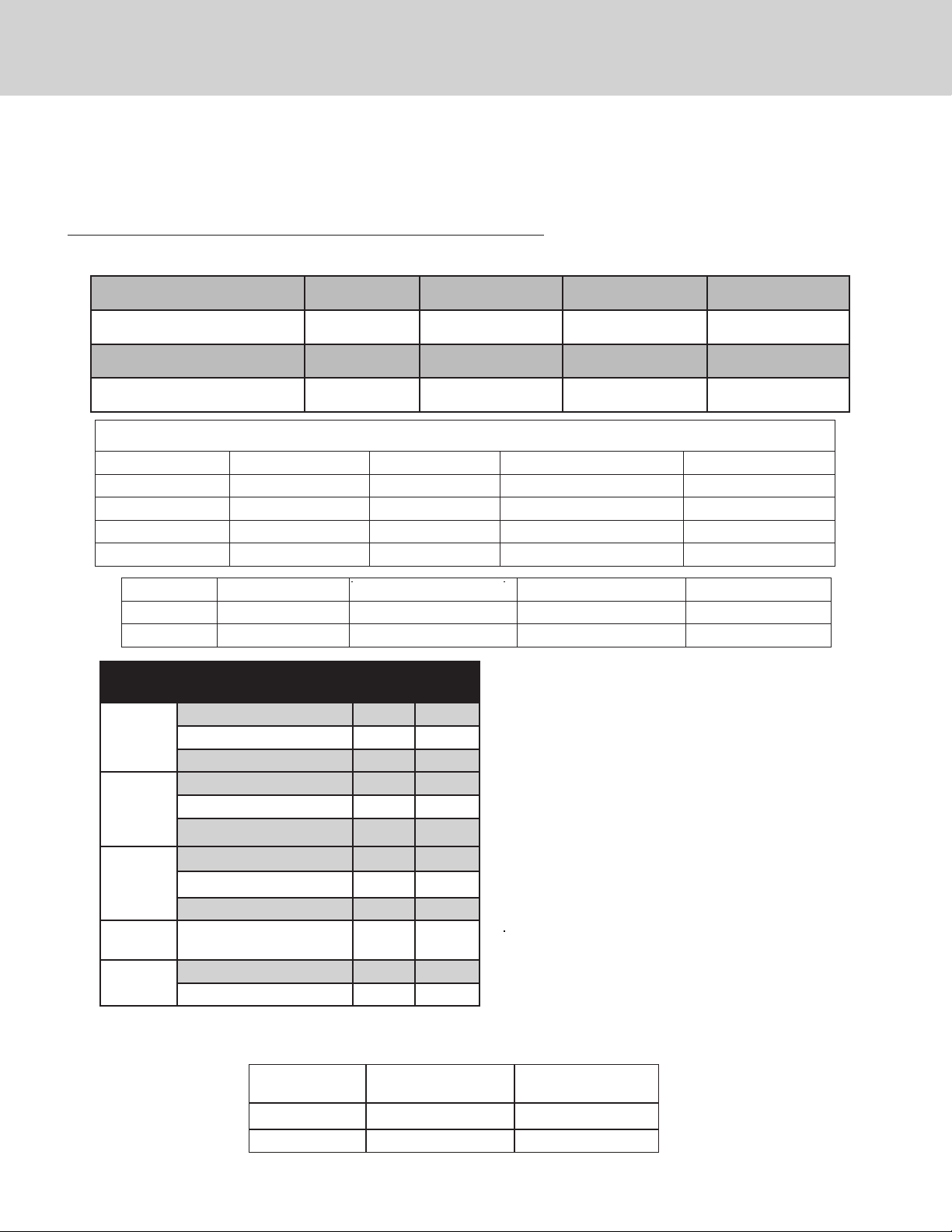
Ensure that the gas supplied meets with the minimum pressure requirements. Do
not operate the grill on any gas other than that for which the grill has been set.
Fuel WC Max Inlet WC Min Under
Full Load
Nat Gas 10 in 4 in
LP 14 in 11 in
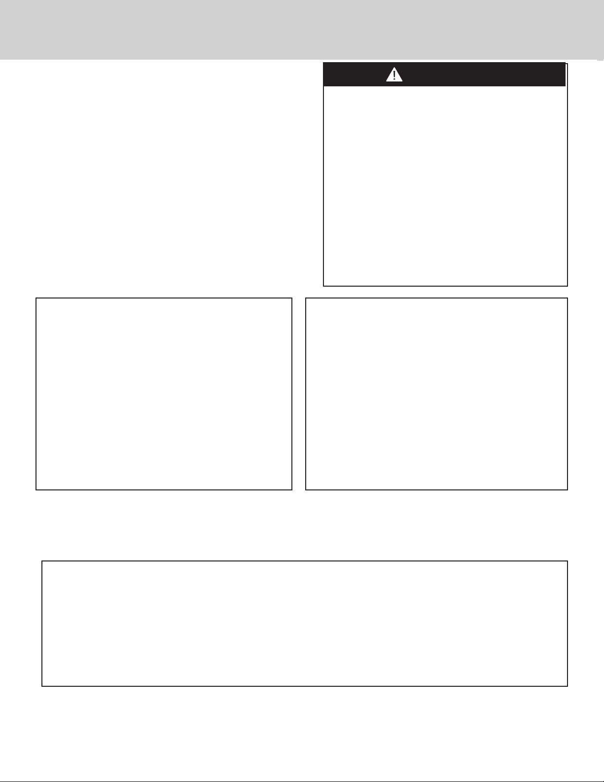
MODEL-SPECIFIC BTU OUTPUTS
MODEL H BURNER (Btu) ROTISSERIE (Btu) PROSEAR™ / TRIDENT(Btu) TOTAL INPUT
30 W. 1 @ 25,000 Nat / LP 1 @ 14,000 Nat / LP 1 @ 21,000 Nat / LP 62,000 Btu/Hr Nat / LP
36” W. 2 @ 25,000 Nat / LP 1 @ 14,000 Nat / LP 1 @ 21,000 Nat / LP 87,000 Btu/Hr Nat / LP
42” W. 2 @ 25,000 Nat / LP 1 @ 16,000 Nat / LP 1 @ 21,000 Nat / LP 89,000 Btu/Hr Nat / LP
54” W. 3 @ 25,000 Nat / LP 2 @ 14,000 Nat / LP 1 @ 21,000 Nat / LP 126,000 Btu/Hr Nat / LP
MODEL TOP BURNER (Btu) OUTER TOP BURNER (Btu) INNER TOP BURNER (Btu) TOTAL INPUT
Side Burner 1 @ 15,000 Nat / LP N/A N/A 30,000 Btu/Hr Nat / LP
Power Burner N/A 1 @ 34,000 1 @ 13,000 47,000 Btu/Hr Nat / LP
Models NG LP
36”
Main Burner 41 53
ProSear /Trident Burner 44 55
IR Rotisserie 50 57
30” / 54”
Main Burner* 41L** 53L**
ProSear /Trident Burner 42 54
IR Rotisserie 50 57
42”
Main Burner* 41L** 53L**
ProSear /Trident Burner 42 54
IR Rotisserie 48 56
Side
Burner
Top Burner #185 #115
Power
Burner
Outer Burner 50L** 57L**
Inner Burner 35L** 50L**
Internal Pipe Diameter 10 ft. 20 ft. 30 ft. 40 ft.
3/4” 360,000 BTU 245,000 BTU 198,000 BTU 169,000 BTU
Internal Pipe Diameter 50 ft. 60 ft. 70 ft. 80 ft.
3/4” 150,000 BTU 135,000 BTU 123,000 BTU 116,000 BTU
4
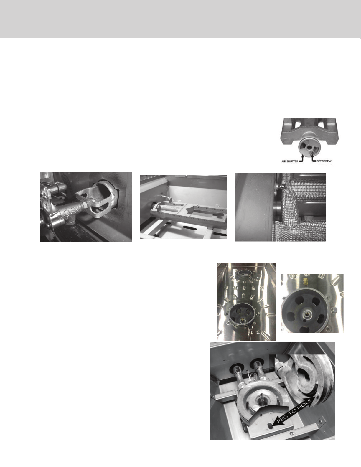
Refer to the chart to install correct ori ces.
Outdoor Grills
• Remove cooking grates and briquette trays.
• Remove the main burners, lift up and then back, up and out.
• Remove the sear burner and lift up and then back, up and out.
• Maintenance: check burner throat for spider webs, run a bottle brush around the inside diameter, wire brush over burner to insure ports are
clear.
• Using the ½” deep socket remove the ori ces from the burner valves. Be sure to support the socket straight and true.
• Using the deep socket install the proper ori ces completely onto the valve. Hold the socket straight and true.
• Remove the rear rotisserie access panel cover plate w/ phillips screwdriver. (one screw on rear hood)
• Remove the rotisserie burner ori ce using the ½” open end wrench. Install the speci ed ori ces.
• On cabinet models, remove the back regulator access panel (four screws) with the phillips screw driver.
• Built in models, under the enclosure, the regulator is located at the rear of the grill.
• Remove the regulator and connector (brass elbow – LP, black pipe 90 degree elbow - NG) from the manifold. Use
fresh pipe dope or tape to install the regulator and elbow supplied in kit.
• Adjust air shutters to minimize yellow ames. (Only applies to brass burners)
• Replace all burners, briquette trays, and grates.
Converting the Grill Burners
Ori ce / Venturi Proper Position
ProSear / Trident Burner pushed all
the way onto the ori ce
Main Burner pushed all the way
onto the ori ce
Side Burner Accessory
• Remove cooking grates.
• Remove the brass burner cap.
• Using the ½” deep socket remove the ori ces from the burner valves. Be sure to
support the socket straight and true. Install the proper ori ces completely onto valve.
Hold the socket straight and true.
• Remove the regulator and connector (brass elbow – LP, black pipe 90 degree elbow -
NG) from the manifold. Use fresh pipe dope or tape to install the regulator and elbow
supplied in kit.
• Open “LP” air shutters three-quarters.
• Open “NG” air shutters one half.
• Replace all burners cap and grates.
Power Burner Accessory
• Remove cooking grates.
• Remove the brass burners, lift up and then back, up and out.
• Using the ½” deep socket remove the ori ces from the burner valves.
Be sure to support the socket straight and true. Install the proper
ori ces completely onto the valve. Hold the socket straight and true.
• Remove the regulator and connector (brass elbow – LP, black pipe 90
degree elbow - NG) from the manifold. Use fresh pipe dope or tape to
install the regulator and elbow supplied in kit.
• Open “LP” air shutters three-quarters.
• Open “NG” air shutters one half.
• Replace all burners and grates. Make sure the burner is seated
correctly on the frame with the brass peg inside the positioning hole
5
Checking for Gas Leaks
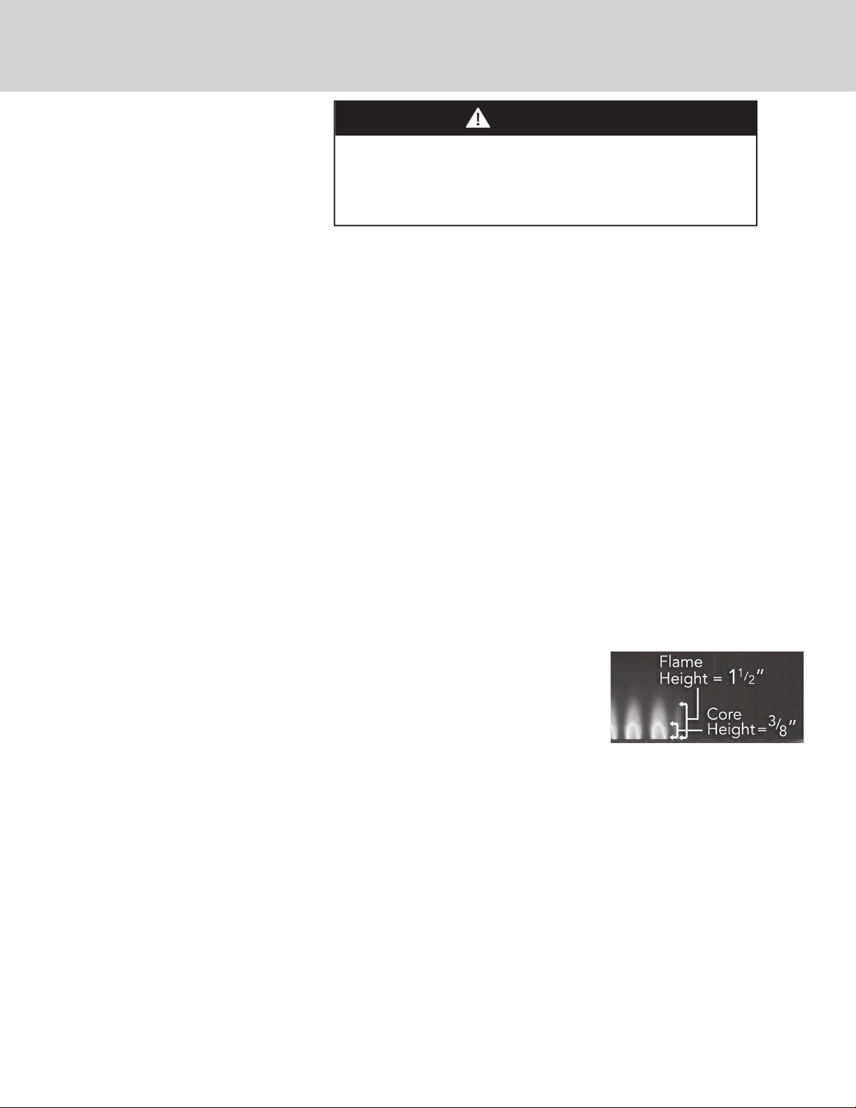
•ADJUSTING BURNER FLAME
• Replace the burners. Light the grill to check ame height. Adjust low ame height with the 3/32” slot blade screw driver.
• Turn the burner valve to the low position. Hold the valve stem in position by hand and insert the screwdriver into the hole in
the valve stem. Turn the screwdriver right or clockwise to reduce ame and left or counter
clockwise to increase ame height.
• Open and close each valve twice to insure the ame height did not change. Re-install all parts
and replace all panels removed
WARNING
To prevent re or explosion hazard, DO NOT smoke or allow
any potential source of ignition (sparks, electrical arcing, etc)
in the area while performing a leak test. Leak tests should be
conducted outdoors only. Never conduct a leak test using re or
ame.
Li
gh
tin
g
Your Gri
ll
For the Main Burner, ProSear™ /Trident Burner or Accessory Burners:
Push and hold the control knob in for 5-7 seconds, allowing the igniter to heat up. Then rotate the knob to “LITE”. After ignition, set
the knob to the desired heat setting.
For the Rotisserie Burner:
The rotisserie burner features a thermocouple sensor with a safety valve that automatically shuts o the ow of gas if the burner
goes out.
To light the rotisserie burner, push and hold the control knob in for 2 seconds and then turn the knob to the “LITE” position.
After ignition CONTINUE HOLDING THE CONTROL KNOB IN for 30 to 60 seconds. During this time the thermocouple will heat up
and the safety valve will remain open.
If you release the control knob before the thermocouple has heated up, the safety valve will shut o the ow of gas to the rotisserie
burner and you will have to re-light the burner.
Create a soapy solution of 1 part soap and 3 parts water.
• Con rm that all control knobs are in the o position.
• Turn on the fuel supply. For natural gas, turn the valve handle 1/4 turn to align with the gas ow.
• For L.P., turn the cylinder valve knob counter clockwise one full rotation.
• Apply the soap solution generously by paint brush or squirt bottle on all connections and ttings.
• If bubbles appear to “grow” on any of the connections, you have a gas leak. IMMEDIATELY turn o the gas supply.
Fixing a Gas Leak:
• Shut o the gas supply
• Turn all grill controls to the “ON” position to purge the grill of any gas build-up, then turn the controls back “OFF”.
• Wash o the soapy solution with cold water and dry.
• Tighten the loose joint, or replace the faulty part with manufacturer-recommended replacement parts.
• DO NOT attempt to repair the L.P. cylinder valve if it is damaged. The only way to safely resolve a damaged cylinder is to REPLACE IT.
• Repeat the leak test to ensure that no leaks are present.
Final Preparation
This appliance was converted on __________________day-month-year to _____________ gas
with the ____________________________________(model number of kit used) Conversion Kit
by:
(name and address of organization making the conversion), which accepts the responsibility that
this conversion has been properly made.
PF030427B
Note: When the conversion is complete, place the labels below in the required locations.
Conversion label
Complete the informaion on this label with a permanent marker and place next to the rating label under the drip tray
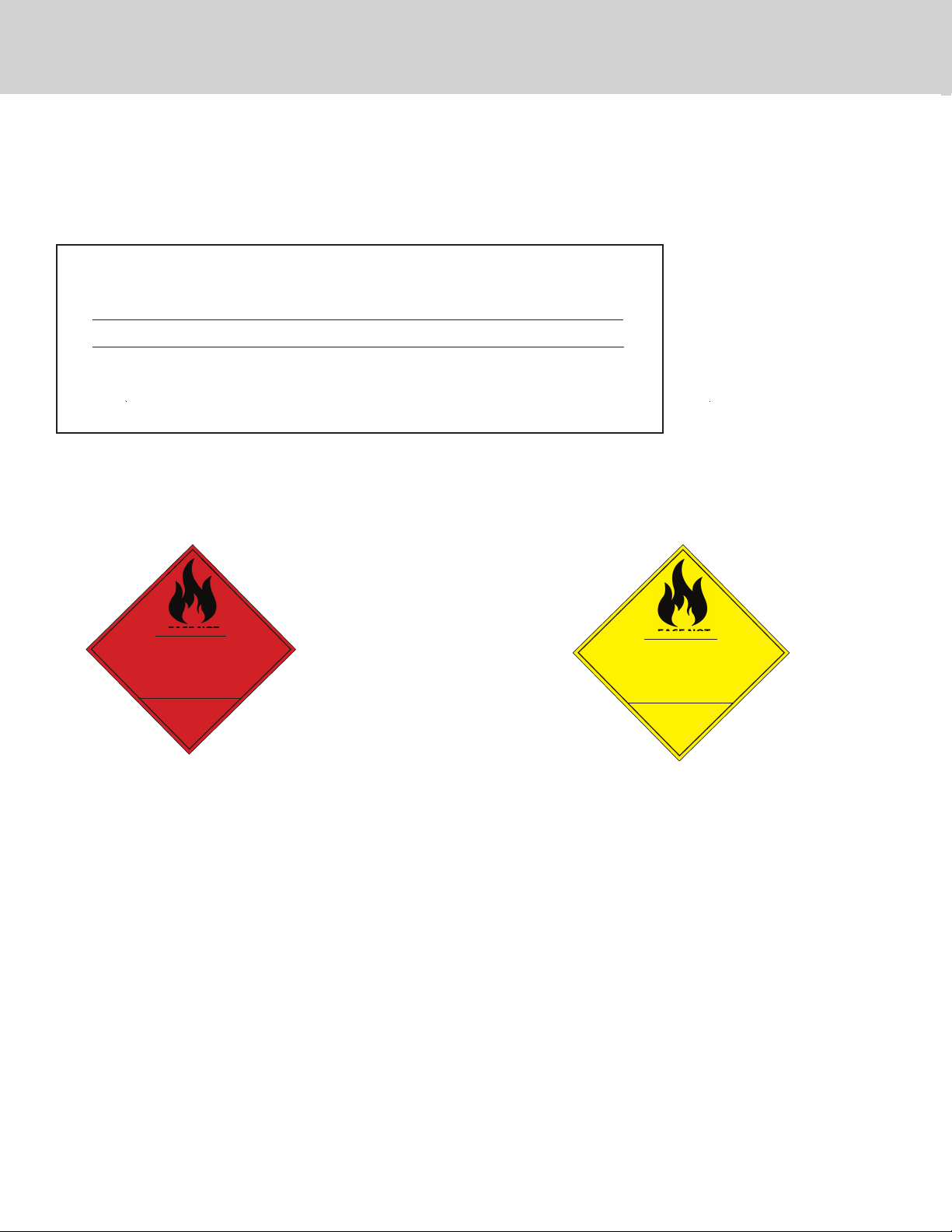
Gas Identi cation label
Replace the triangle label on the back of the unit with the one in the kit.
Red triangle will go on the grill converted to Natural. Yellow triangle will go on the unit converted to LP
PLEASE NOTE
THIS APPLIANCE HAS
BEEN MANUFACTURED
TO OPERATE ON
NATURAL GAS
LEASE NOT
071523-000
PLEASE NOTE
THIS APPLIANCE HAS
BEEN MANUFACTURED
TO OPERATE ON
LIQUID PROPANE GAS
L
E
A
S
E
N
O
T
071522-000
068907-000C (073021)