Loading ...
Loading ...
Loading ...
INSTALLATION INSTRUCTIONS
13
Step 8: Mount the Indoor Unit
If new connective piping was installed to the outdoor unit, complete the following:
1. If the refrigerant piping has already been passed through the wall, proceed to step 4.
2. Otherwise, double check that the ends of the refrigerant pipes are sealed to prevent dirt or foreign
materials from entering the pipes.
3. Slowly pass the wrapped bundle of refrigerant pipes, drain hose and signal wire through the hole in
the wall.
4. Hook the top of the indoor unit on the upper hook of the mounting plate.
5. Check that the unit is hooked fi rmly on mounting by applying slight pressure to the left and right-hand
sides of the unit. The unit should not jiggle or shift.
6. Using even pressure, push down on the bottom half of the unit. Keep pushing down until the unit snaps
onto the hooks along the bottom of the mounting plate.
7. Check that the unit is fi rmly mounted by applying slight pressure to the left and right-hand sides of the
unit.
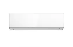
If refrigerant piping is already embedded in the wall, complete the following:
1. Hook the top of the indoor unit on the upper hook of the mounting plate.
2. Use a bracket or wedge to prop up the unit, allowing enough room to connect the refrigerant piping,
signal cable and drain hose.
3. Connect the drain hose and refrigerant piping. Refer to the Refrigerant Piping Connection section for
more information.
4. Keep the pipe connection point exposed to perform the leak test. Refer to the Electrical Checks and Leak
Checks section for more information.
5. After the leak test, wrap the connection point with insulation tape.
6. Remove the bracket or wedge that is propping up the unit.
7. Using even pressure, push down on the bottom half of the unit. Keep pushing down until the unit snaps
onto the hooks along the bottom of the mounting plate.
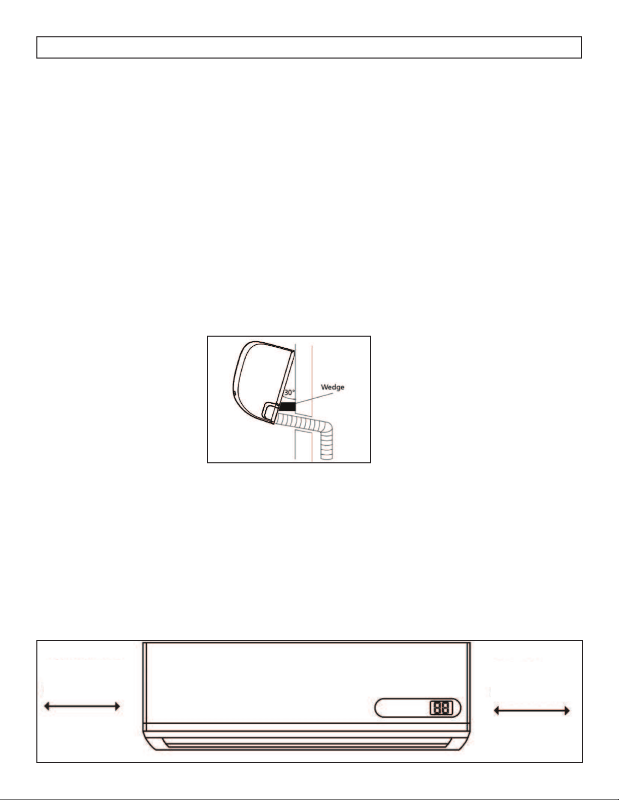
Unit is Adjustable
The hooks on the mounting plate are smaller than the holes on the back of the unit. The unit can be
adjusted left or right by approximately 30 - 50 mm (1.25 - 1.95 in) depending on the model.
10 - 20 mm
( 0.4 - 0.8”)
10 - 20 mm
( 0.4 - 0.8”)
Loading ...
Loading ...
Loading ...