Loading ...
Loading ...
Loading ...
11
INSTALLATION INSTRUCTIONS
Step 6: Connect the Signal Cable
The signal cable enables communication between the indoor and outdoor units. You must fi rst choose the
right cable size before preparing it for connection.
Cable types:
• Indoor Power Cable (if applicable): SOW
• Outdoor Power Cable: SOW
• Signal Cable: SOW
Minimum Cross Sectional Area of
Power and Signal Cables
Appliance Amps (A) AWG
10 18
13 16
18 14
25 12
30 10
CHOOSE THE RIGHT SIZE CABLE
The size of the power supply cable, signal cable, fuse and
switch needed is determined by the maximum current in the
unit. The maximum current is indicated on the rating plate
located on the side panel of the unit. Refer to this rating plate to
choose the right cable, fuse and switch.
Take Note of Fuse Specifi cations
The air conditioner circuit board (PCB) is designed with a fuse to provide over current protection. The
specifi cations of the fuse are printed on the circuit board, such as: T3.15A/250VAC, T5A/250VAC, etc.
1. Prepare the cable for connection:
a. Using wire strippers, strip the rubber jacket from both ends of the signal cable to reveal
about 40 mm (1.57 in) of the wires inside.
b. Strip the insulation from the ends of the wires.
c. Using wire crimper, crimp u-type lugs on the ends of the wires.
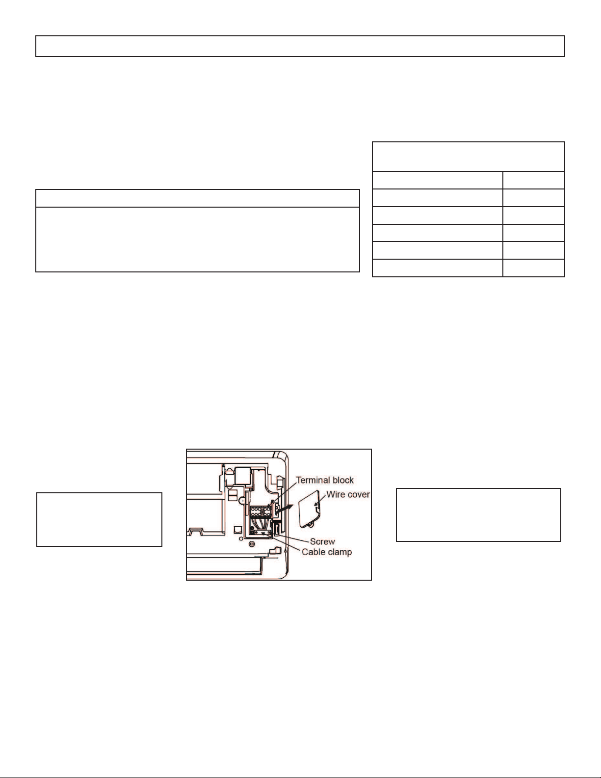
2. Open the front panel of the indoor unit.
3. Using a screwdriver, open the wire box cover on the right side of the unit. This will reveal the terminal
block.
4. Unscrew the cable clamp below the terminal block and place it to the side.
5. Facing the back of the unit, remove the plastic panel on the bottom left-hand side.
6. Feed the signal wire through this slot, from the back of the unit to the front.
7. Facing the front of the unit, match the wire colours with the labels on the terminal block, connect the
u-lug and fi rmly screw each wire to its corresponding terminal.
8. After checking to make sure every connection is secure, use the cable clamp to fasten the signal cable
to the unit. Screw the cable clamp down tightly.
9. Replace the wire cover on the front of the unit and the plastic panel on the back.
The wiring diagram is
located on the inside of
the wire cover on the
indoor unit.
Note: Pay attention to the live
wire. While crimping wires,
make sure to distinguish the Live
(“L”) Wire and other wires.
Loading ...
Loading ...
Loading ...