Loading ...
Loading ...
Loading ...
11
Warning!
All electrical work should be carried out by a suitably qualified and authorized electrician.
No alterations or willful changes in the electricity supply should be carried out.
Fitting guidelines
The oven is manufactured to work with signal-phase alternat
ing current (120V supply
system).
The connection diagram is also found on the cover of the connection holder.
Remember that the connection wire should match the connection type and the power
rating of the oven.
Before connecting the oven to the power supply it is important to read the information on
the data plate and the connection diagram.
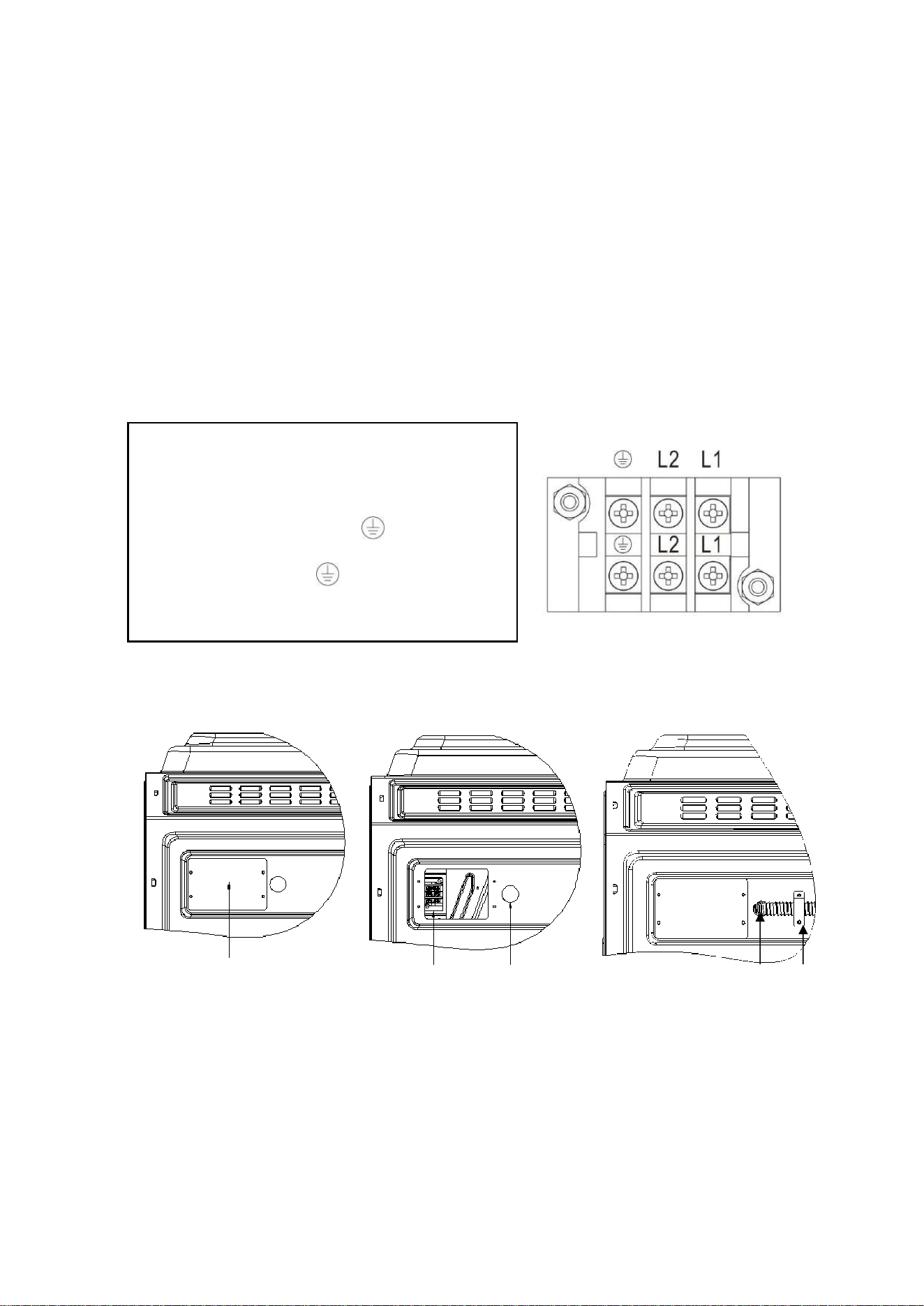
CONNECTION DIAGRAM
Caution!Voltage of heating elements 240V
Caution! In the event of any connection the safety
wire must be connected to the terminal
For 240V,connection ways as below:
Green Wire connects to
Black Wire connects to L2
Red Wire connects to L1
Fig. 1.2Fig. 1.2
Bellows wiring method:
Step 1: Remove the wiring strip, as shown Fig.1.1
Wiring port baffle
Step 2: connect the ground wire, red wire L1 and black wire L2 of the bellows to the ground wire, red wire
L1 and black wire L2 of the wiring seat respectively
. The bellows is stretched out from the outlet of the
bellows and pressed on the upper cover by the wire clamp. As shown Fig.1.2/Fig.1.3
Wiring seat
Bellows outlet Bellows Wire clamp
:
Fig.1.3Fig.1.2Fig.1.1
Loading ...
Loading ...
Loading ...