Loading ...
Loading ...
Loading ...
ItemPartName Qty.
Z HexNut, 5/16-18
(approx. dia.ofhole5/16 in.) ........... 9
Z HexNut, 1t4-20
(approx.dia.ofhole114in.) ............ 2
AA Lockwasher,5/I 6 in. ExternalType
(approx.die.ofhole5116in.) ........... 11
AA Lockwasher,1/4 in. ExternalType
(approx.alia.of h ale1/4 in.) ............ 2
AA LockwasherNo. 10 ExternalType
(approx.dia.of hole3t16 in.) ........... 1
AB CarriageBolt,5/16-18 x 3/4 in. long ....... 4
AC Rip FenceGuideBarSpacer .............. 2
AD Wire Tie .............................. 2
AE Thumbscrew,5/1G-18x 1in. long .......... 1
AF Screw PanHd. 10-32 x3/4 .............. 1
AG Flat Washer(dia. ofhole 21/64) ........... 2
The followingpartsareincludedwith Model113.298031 and
113.298151.
A Leg ................................... 4
8 SideStiffener ........................... 2
C EndStiffener ............................ 2
D TableExtension(113.298031) .............. 2
TableExtension(113.298151) .............. I
E Motor ................................. I
Pkg.of Miscellaneous_mall Parts,No. 62752for Legs
Consistingofthe Following:
F Hex HeadScrew5116-18 x 1-1/4 in. long .... 4,
G Lockwasher,1/4 in. ExternalType
(approx.dia.of hole1/4 in.) .............. 24
G Lockwasher,5/16 in. ExternalType
(epprox. dia.of hole 5/16 in.) ............ 4
H Hex Nut, 1/4-20
(approx.dia.of hole1/4 in.) ............. 24
H Hex Nut, 5/16-18
(approx.dia.of hole5/16 in.) ............. 4
H Hex Nut, 1/2-13
(approx.dia.of hole1]2 in.) ............. 8
J FlatWasher(dia. of hole,11/32 in.) .......... 8
A
F
J K L
©
G H
Item
K
L
PertName Qty.
TrussHeadScrew,1/4-20 x 5/8 in.long
(top of screwisrounded) ................ 24
LevelingFoot ......................... 4
Pkg.of MiscellaneousSmall PartsNo. 62745 for
TableExtensions(1 ea.for Model113.298151,
2ea.for Model 113.298031)
Consistingof the following:
F HexHd, Screw,5/16-18 x I-1/4 in. long ..... 4
G Lockwasher,ExternalType
(approx. dia. of hole 1/4 in.) .............. 8
G Lockwasher,ExternalType
(approx.dia.of hale5/16 in.) ............. 4
H HexNut, 1/4-20
(approx.alia.of hole114in.) .............. 8
H Hex Nut, 5/16-18
(approx.dia.of hole5/16 in.) .............. 8
K TrussHeadScrew, 1/4-20 x 1 in. long
(top of screwisrounded) ................ 8
M Corner_;tiffener Bracket .................. 2
N CornerSupportBracket .................. 2
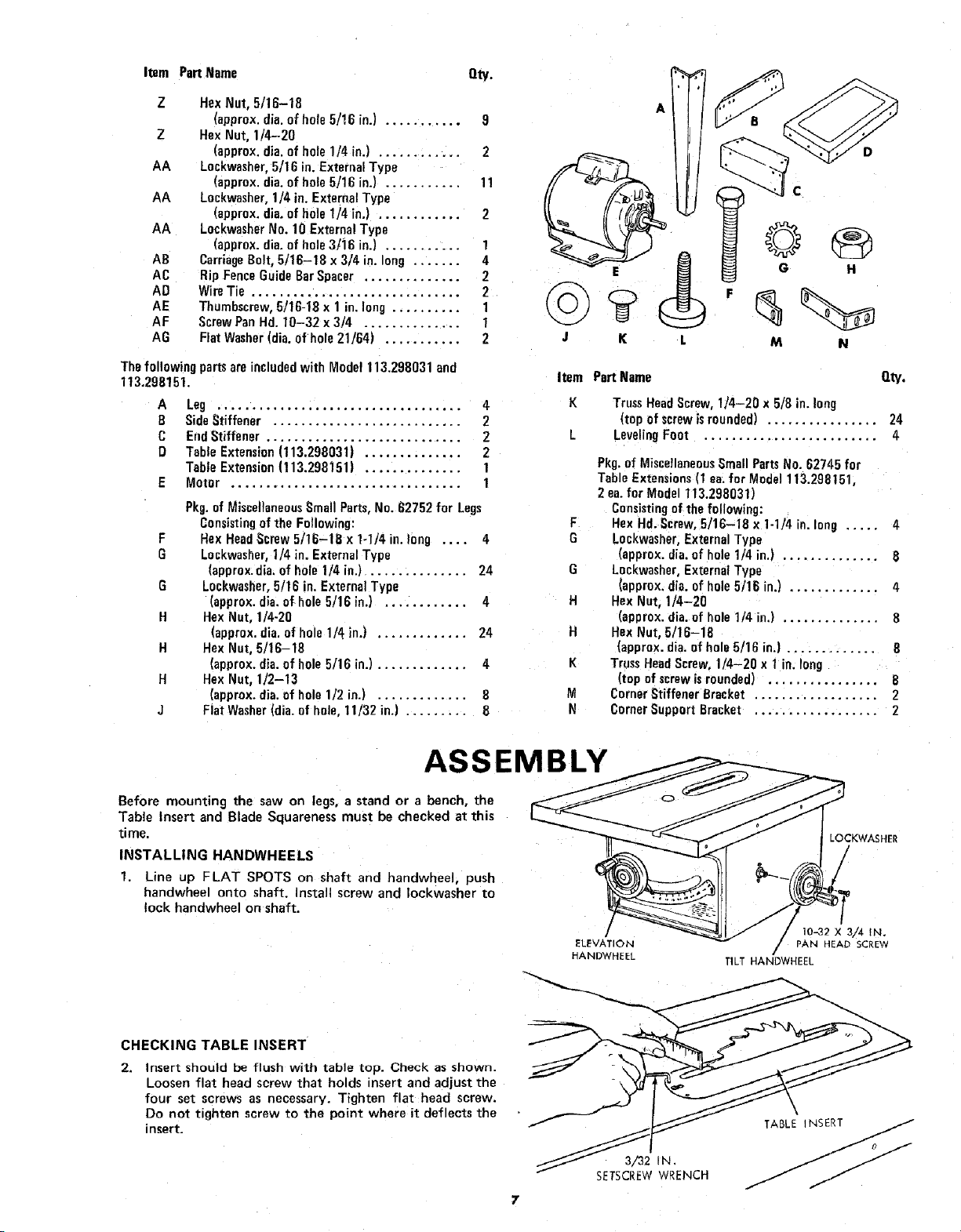
ASSEMBLY
Before mounting the saw on legs, a stand or a bench, the
Table Insert and Blade Squareness must be checked at this
time.
INSTALLING HANDWHEELS
1. Line up FLAT SPOTS on shaft and hardwheel, push
handwheel onto shaft. Install screw and Iockwasher to
lock handwheel on shaft.
ELEVATION
HANDWHEEL
LOCKWASHER
/
10-32 X 3/4 IN.
PAN HEAD SCREW
/
TILT HANDWHEEL
CHECKING TABLE INSERT
2.
Insert should be flush with table top. Check as shown.
Loosen flat head screw that holds insert and adjust the
four set screws as necessary. Tighten flat head screw.
Do not tighten screw to the point where it deflects the
insert.
3/32 IN.
SETSCREWWRENCH
\
TABLE INSERT
Loading ...
Loading ...
Loading ...