
DE’LONGHI
COOKING
INSTALLATION and SERVICE INSTRUCTIONS
USE and CARE INSTRUCTIONS
SLI 905
CERAMIC INDUCTION COOKTOP
distributed by
ELBA Appliances Australia
(a Division of Fisher&Paykel Australia)

22

33
Dear Customer,
Thank you for having purchased and given your preference
to our product.
The safety precautions and recommendations reported
below are for your own safety and that of others. They
will also provide a means by which to make full use of the
features oered by your appliance.
Please keep this booklet in a safe place. It may be useful
in future, either to yourself or to others in the event that
doubts should arise relating to its operation.
This appliance must be used only for the task it
has explicitly been designed for, that is for cooking
foodstus. Any other form of usage is to be considered
as inappropriate and therefore dangerous.
The manufacturer declines all responsibility in the
event of damage caused by improper, incorrect or
illogical use of the appliance or be faulty installation.
PRODUCT LABEL
This appliance has been designed and constructed in accordance with the following
codes and specications:
AS/NZS 60335.1 General Requirements for Domestic electrical appliances
AS/NSZ 60335.2.6
Particular Requirements for Domestic electrical cooking appliances
AS/NZS CISPR 14.1 Electromagnetic Compatibility Requirements

44
IMPORTANT SAFETY PRECAUTIONS AND RECOMMENDATIONS
IMPORTANT: This appliance is designed and manufactured
solely for the cooking of domestic (household) food and is
not suitable for any non domestic application and therefore
should not be used in a commercial environment.
The appliance guarantee will be void if the appliance is used
within a non domestic environment i.e. a semi commercial,
commercial or communal environment.
Read the instructions carefully before installing and using
the appliance.
• This appliance has been designed and manufactured in
compliance with the applicable standards for the household
cooking products, including those for surface temperatures.
Some people with sensitive skin may have a more pronounced
temperature perception with some components although these
parts are within the limits allowed by the norms.
The complete safety of the appliance also depends on the correct
use, we therefore recommend to always pay a extreme attention
while using the product, especially in the presence of children.
• After having unpacked the appliance, check to ensure that it is
not damaged.
In case of doubt, do not use it and consult your supplier or a
professionally qualied technician.
• Packing elements (i.e. plastic bags, polystyrene foam, nails,
packing straps, etc.) should not be left around within easy reach
of children, as these may cause serious injuries.
• Some appliances are supplied with a protective lm on steel and
aluminium parts. This lm must be removed before using the
appliance.
• IMPORTANT: The use of suitable protective clothing/gloves is
recommended when handling or cleaning this appliance.

55
• Do not attempt to modify the technical characteristics of the
appliance as this may become dangerous to use. The manufacturer
declines all responsibility for any inconvenience resulting from the
inobservance of this condition.
• Do not operate your appliance by means of an external timer or
separate remote-control system.
• Do not carry out cleaning or maintenance operations on the
appliance without having previously disconnected it from the electric
power supply.
• Do not use a steam cleaner because the moisture can get into the
appliance therefore making it unsafe.
• Do not cover the hob with aluminium foils.
• Do not touch the appliance with wet or damp hands (or feet).
• Do not use the appliance whilst in bare feet.
• If you should decide not to use this appliance any longer (or
decide to substitute another model), before disposing of it, it is
recommended that it be made inoperative in an appropriate manner
in accordance to health and environmental protection regulations,
ensuring in particular that all potentially hazardous parts be made
harmless, especially in relation to children who could play with
unused appliances.
• The various components of the appliance are recyclable. Dispose
of them in accordance with the regulations in force in your country.
If the appliance is to be scrapped, remove the power cord.
• After use, ensure that the controls are in the o position.
• Children less than 8 years of age shall be kept away unless
continuously supervised.
• This appliance can be used by children aged from 8 years and
above and persons with reduced physical, sensory or mental
capabilities or lack of experience and knowledge if they have been
given supervision or instruction concerning use of the appliance in
a safe way and understand the hazards involved. Children shall not
play with the appliance. Cleaning and user maintenance shall not
be made by children without supervision.

66
• The manufacturer declines all liability for injury to persons or damage
to property caused by incorrect or improper use of the appliance.
• WARNING: During use the appliance and its accessible parts
become hot; they remain hot for some time after use.
– Care should be taken to avoid touching heating elements on
the hob.
– To avoid burns and scalds, young children should be kept
away.
• Make sure that electrical cables connecting other appliances in
the proximity of the cooktop cannot come into contact with the
hob.
• WARNING: Unattended cooking on a hob with fat or oil can be
dangerous and may result in re. NEVER try to extinguish a re
with water, but switch o the appliance and then cover ame e.g.
with a lid or a re blanket.
• WARNING: Danger of re: do not store items on the cooking
surfaces.
• Do not place or leave empty pans on the glass ceramic hob.
• Do not allow heavy or sharp objects to drop on the glass ceramic
hob.
• Do not scratch the hob with sharp objects. Don’t use the hob as
a work surface.
• WARNING: If the hob is cracked or otherwise damaged by falling
objects etc., disconnect the appliance from the electrical power
supply to avoid the possibility of electric shock and call Customer
Service.
• WARNING: When correctly installed, your product meets all
safety requirements laid down for this type of product category.
However special care should be taken around the underneath
of the appliance as this area is not designed or intended to be
touched and may contain sharp or rough edges, that may cause
injury.
• CAUTION: The cooking process has to be supervised. A short
term cooking process has to be supervised continuously.

77
• Models provided with power supply cable. If the power supply
cable is damaged, it must be replaced only by an authorised
service agent in order to avoid a hazard.
• If the appliance is not tted with a supply cord and a plug, or with
other means for disconnection from the supply mains having a
contact separation in all poles that provide full disconnection under
overvoltage category III conditions, means for disconnection
must be incorporated in the xed wiring in accordance with the
wiring rules.
• WARNING: The appliance and its accessible parts become hot
during use.
Care should be taken to avoid touching heating elements.
Children less than 8 years of age shall be kept away unless
continuously supervised.
• WARNING: Use only hob guards designed by the manufacturer
of the cooking appliance or indicated by the manufacturer of the
appliance in the instructions for use as suitable or hob guards
incorporated in the appliance. The use of inappropriate guards
can cause accidents.
• Do NOT place combustible materials or products on this appliance
at any time.
• Do NOT spray aerosols in the vicinity of this appliance while it is
in use.
• IMPORTANT NOTE: This appliance shall not be used as a space
heater, especially if installed in marine craft or caravans.
• INDUCTION HOBS:
– Metallic objects such as knives, forks, spoons and lids should
not be placed on the hob surface since they can get hot.
– Do not use metallic kitchen utensils (e.g. ladles). It is preferable
to use plastic or wood kitchen utensils.
– Please use pans of recommended size (see minimum pan
diameter recommended). It is not advisable to use pans
smaller than the cooking zone. The pans have to be placed in
the centre of the cooking zone.
– Do not use defective pans or pans with a curved bottom.

88
– Please use suitable pans marked for induction cooking.
– Please keep your distance from the electromagnetic elds by
standing 5-10 cm from the cooking zones. When possible use
the rear cooking zones.
– Magnetic objects (e.g. credit cards, oppy disks, memory
cards) and electronic instruments (e.g. computers) should not
be placed near the induction hob.
– The heating of magnetic tins is forbidden! Closed tins may
explode by exceeding pressure while heating. There is a
burning risk with open tins as well, because the integrated
temperature protection will not work correctly.
– IMPORTANT WARNING: The induction hob complies with the
local applicable Standards for domestic cooking appliances.
Therefore it should not interfere with other electronic units.
Persons with cardiac pacemakers or any other electrical
implants must check with their doctor if they can use an induction
cooking system (and check any possible interferences with
the implants).

99
Advice for
the installer

1010
INSTALLATION
1
IMPORTANT:
• The appliance is designed and approved for domestic use only and should not be
installed in a commercial, semi commercial or communal environment.
Your product will not be guaranteed if installed in any of the above environments
and could aect any third party or public liability insurances you may have.
• This appliance is to be installed only by an authorised person according to the current
local regulations and in observation of the manufacturer’s instructions.
Failure to comply with this condition will render the guarantee invalid.
• Incorrect installation, for which the manufacturer accepts no responsibility, may cause
personal injury of damage.
• This appliance shall only be serviced by authorized personnel.
• Always disconnect the cooktop from mains power supply before carrying out any
maintenance operations or repairs.
• Important: The use of suitable protective clothing/gloves is recommended when
handling or installing this appliance.
• The appliance must be housed in heat resistant units.
• The walls of the units must not be higher than work top and must be capable of
resisting temperatures of 70 °C above room temperature.
• We would point out that the adhesive which bonds the plastic laminate to the
furniture must withstand temperatures not less than 150 °C to avoid delamination.
• Standard installation (not ush): Do not seal the cooktop into the benchtop with
silicone or glue; this makes future servicing dicult. Elba Appl. AUS Service Agent
will not cover the costs of removing the cooktop, or of damage caused by this
removal.
• Do not install the appliance near inammable materials (eg. curtains).
WARNING
When correctly installed, your product meets all safety requirements laid down for
this type of product category.
However special care should be taken around the underneath of the appliance as
this area is not designed or intended to be touched and may contain sharp or rough
edges, that may cause injury.
1111
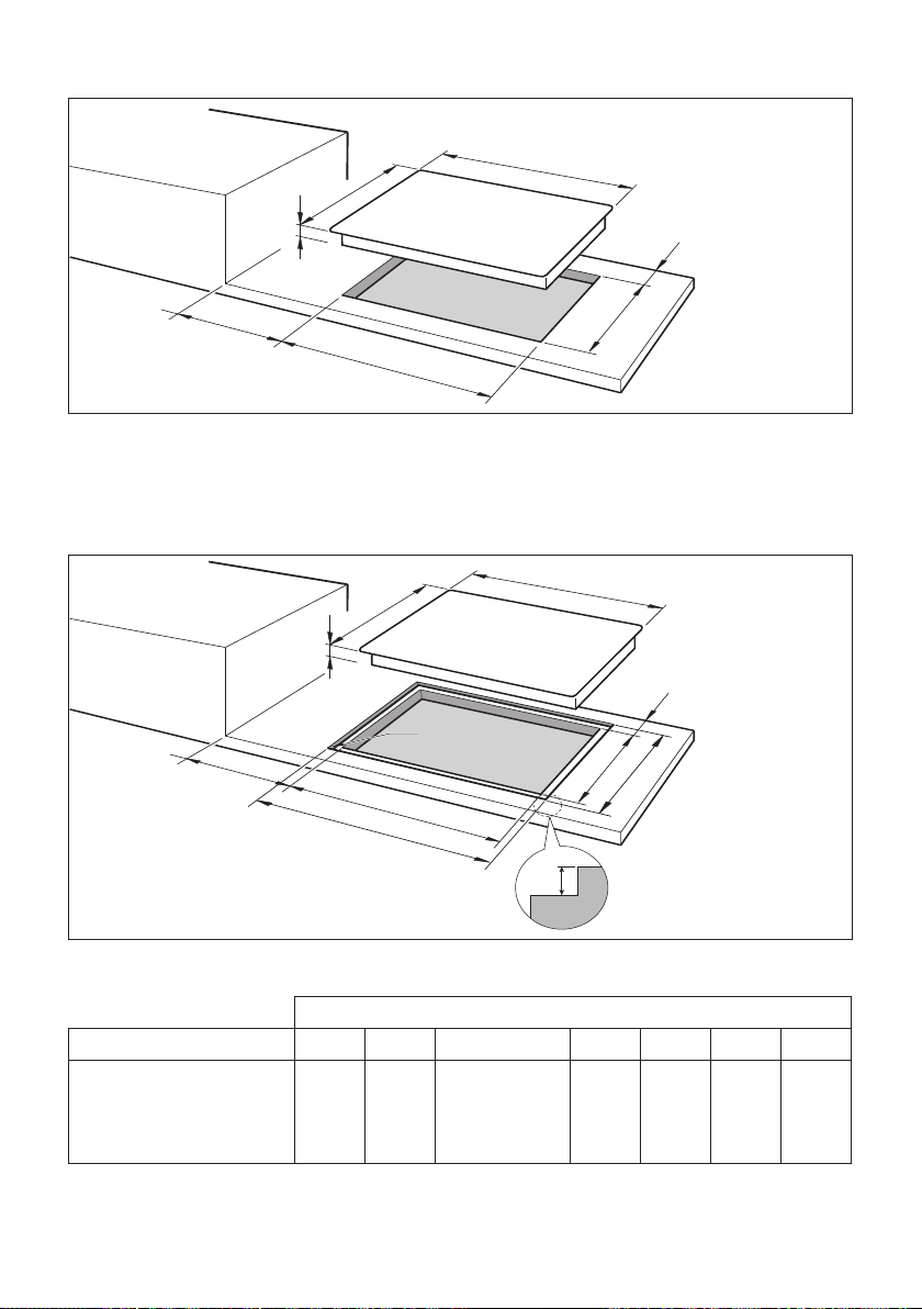
FLUSH INSTALLATION (MODELS WITHOUT METAL TRIM/S ONLY)
If you wish to install the hob ush with the work surface, it is neccessary to execute/carry
out a miling in the hole of the cut-out as indicated in g. 1.1b.
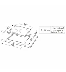
STANDARD INSTALLATION
Measures (mm)
Description A (*) B (*) C (**) D D1 E E1
90cm wide models 900 520
47
or
53 for ush
installation
840 905 480 525
(*) For models with metal trim/s add 4mm to the measurement for each trim.
Example: front metal trim= B+4mm.
(**) from the top of countertop to bottom of cooktop.
E
50 mm
D
50 mm
B
A
C
Fig. 1.1a
E
50 mm
D
B
A
C
E1
D1
R7
6
50 mm
Fig. 1.1b

1212
FITTING REQUIREMENTS
This cooktop can be built into a working surface from 20 mm thick and 600 mm deep.
In order to install the ceramic hob into the kitchen xture, a hole with the dimensions shown
in gures 1.1a or 1.1b has to be made, keeping in consideration the following:
• The cooktop shall not be installed directly above a dishwasher, fridge, freezer, washing
machine or clothes dryer, as the humidity may damage the cooktop electronics.
• If the cooktop is installed above an oven, the oven shall be provided with cooling fan.
The two appliances should be connected to the electrical supply with independent
connections.
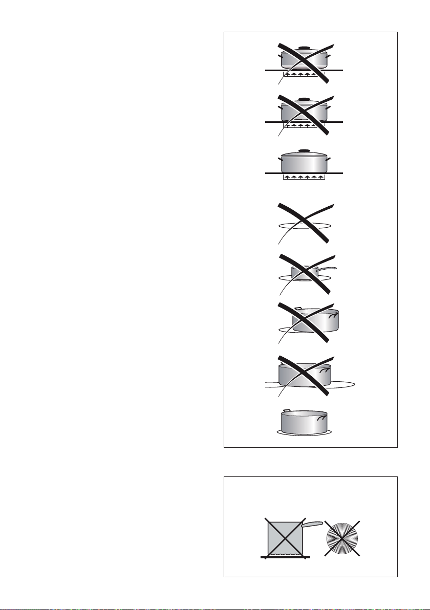
• IMPORTANT WARNING! This cooktop requires adequate supply of fresh, cool
air to fully function. The base of the cooktop must have direct unrestricted
ventilation to the room where the cooktop is installed. Follow the requirements
of gure 1.3 or 1.4.
• There must be a distance of at least 650 mm between the hob and any wall cupboard
or extractor hood positioned immediately above (see g. 1.2).
• Standard installation (not ush): Do not seal the cooktop into the benchtop with silicone
or glue; this makes future servicing dicult. Elba Appl. AUS Service Agent will not
cover the costs of removing the cooktop, or of damage caused by this removal.
• The walls surrounding the cooktop must be made of heat-resistant material.
• Do not install the appliance near inammable materials (eg. curtains).
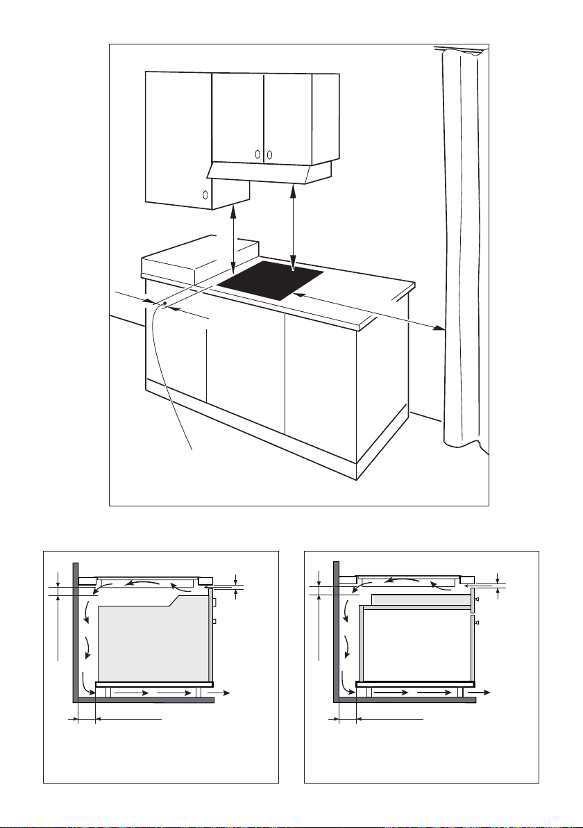
1313
min 5 mm
min 30 mm
min 25 mm
min 5 mm
min 30 mm
min 25 mm
Minimum clearances and
ventilation requirements
(oven installed below)
Minimum clearances and
ventilation requirements
(cupboard or drawer space below)
Oven with
cooling fan
650 mm
500 mm
450 mm
50 mm minimum
between the side of the
cut-out and the side wall
Fig. 1.2
Fig. 1.4Fig. 1.3
1414
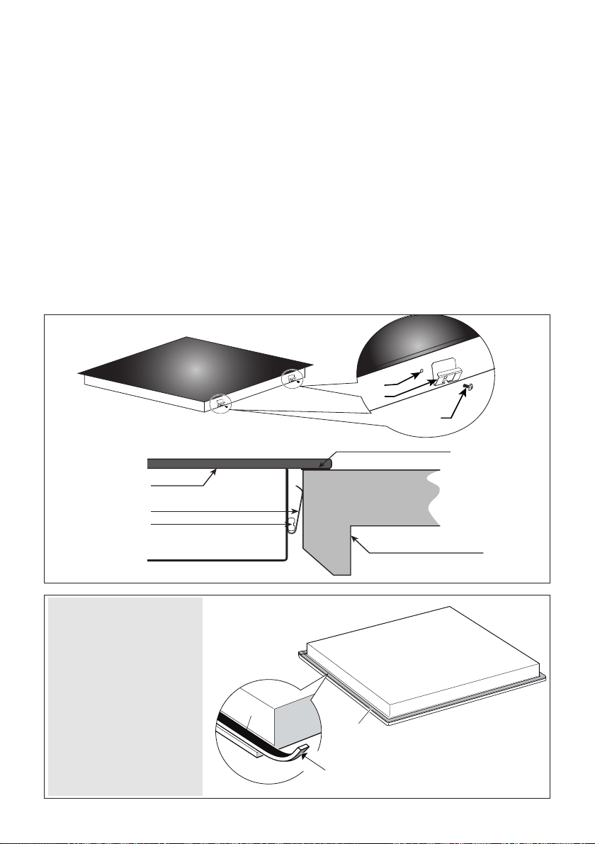
FASTENING THE COOKTOP
Each cooktop is provided with an installation kit including brackets and screws for fastening
the cooktop to benches from 20 mm thick. Before you install the cooktop, make sure that
the work surface is square and level, and no structural members interfere with space
requirements previously indicated.
The kit includes four metal clips “B” and four self-threading screws “A” (g. 1.5).
• Cut the unit according to the dimensions in g. 1.1a or 1.1b.
• Turn the hob upside down and rest the glass side on a soft surface.
• Spread the seal “D” around the edge of the hob (g. 1.6).
• Fasten the metal clips “B” into the hole “C” using the screws A”. Make sure that the
metal clips are mounted correctly as shown in the gure 1.5. The metal clips have to
be tted on front and back (not sides).
• Put the cooktop into the cutout and position it correctly.
• Using a sharp cutter or trimmer knife, trim the excess sealing material around the edge
of the cooktop. Take care not to damage the workbench.
• In case to install the hob ush with the work surface, ll any gaps between the glass
and along the perimeter of the work surface with insulating silicone, and wipe away
any excess.
D
D
Adhesive side
Adhesive side
Fig. 1.6
C
B
A
B
A
Fig. 1.5
Glass
Metal clips
Fixing screw
Worktop / kitchen cabinet
Seal “D”
IMPORTANT: Spread
the sealing material “D”
around the edge of the
hob (edge of the glass).
The sealing material
“D” must be installed
correctly to guarantee a
perfect seal between the
appliance and the unit.
Incorrect installation may
cause irreparable damage
to the appliance.

1515
ELECTRICAL SECTION
2
IMPORTANT: Installation must be carried out according to the manufacturer’s
instructions. Incorrect installation may cause harm and damage to people,
animals or property, for which the manufacturer accepts no responsibility.
Before carrying out any work on the electrical section of the appliance, it must be
disconnected from the mains.
Connection to a good earth wiring system is absolutely essential.
The manufacturer accepts no responsibility for any inconvenience caused by
failure to comply with this rule.
If the hob surface is cracked disconnect the appliance from the mains and contact
the After-Sales Service.
ELECTRICAL REQUIREMENTS
• Connection to the electric power supply must be carried out by a qualied technician
and following the appropriate safety regulations.
• The appliance must be connected to the mains checking that the voltage corresponds
to the value given in the rating plate and that the electrical cable sections can withstand
the load specied on the plate.
• The appliance should be connected directly to the mains placing an omnipolar switch with
minimum opening between the contacts of 3 mm between the appliance and the mains
(Australia and New Zealand only: means providing full disconnection under overvoltage
category III conditions must be incorporated in the xed wiring in accordance with
AS/NZS 3000).
• The power supply cable must not touch the hot parts and must be positioned so that it
does not exceed 50°C above ambient.
• Once the appliance has been installed, the switch must always be in a accessible
position.
N.B. For connections to the mains power supply, never use adaptors, reductions or
multiple power points as these may overheat and catch re.
In the event that installation should require modications to the mains supply wiring system,
it is recommended that a qualied technician be called to carry out substitution.
He should also check that the domestic electrical system is suitable for the power absorbed
by the appliance.
VOLTAGE AND POWER CONSUMPTION
220-240/380-415 V 3N 50-60 Hz 10400 W (45.21 A) (diversity cannot be applied)
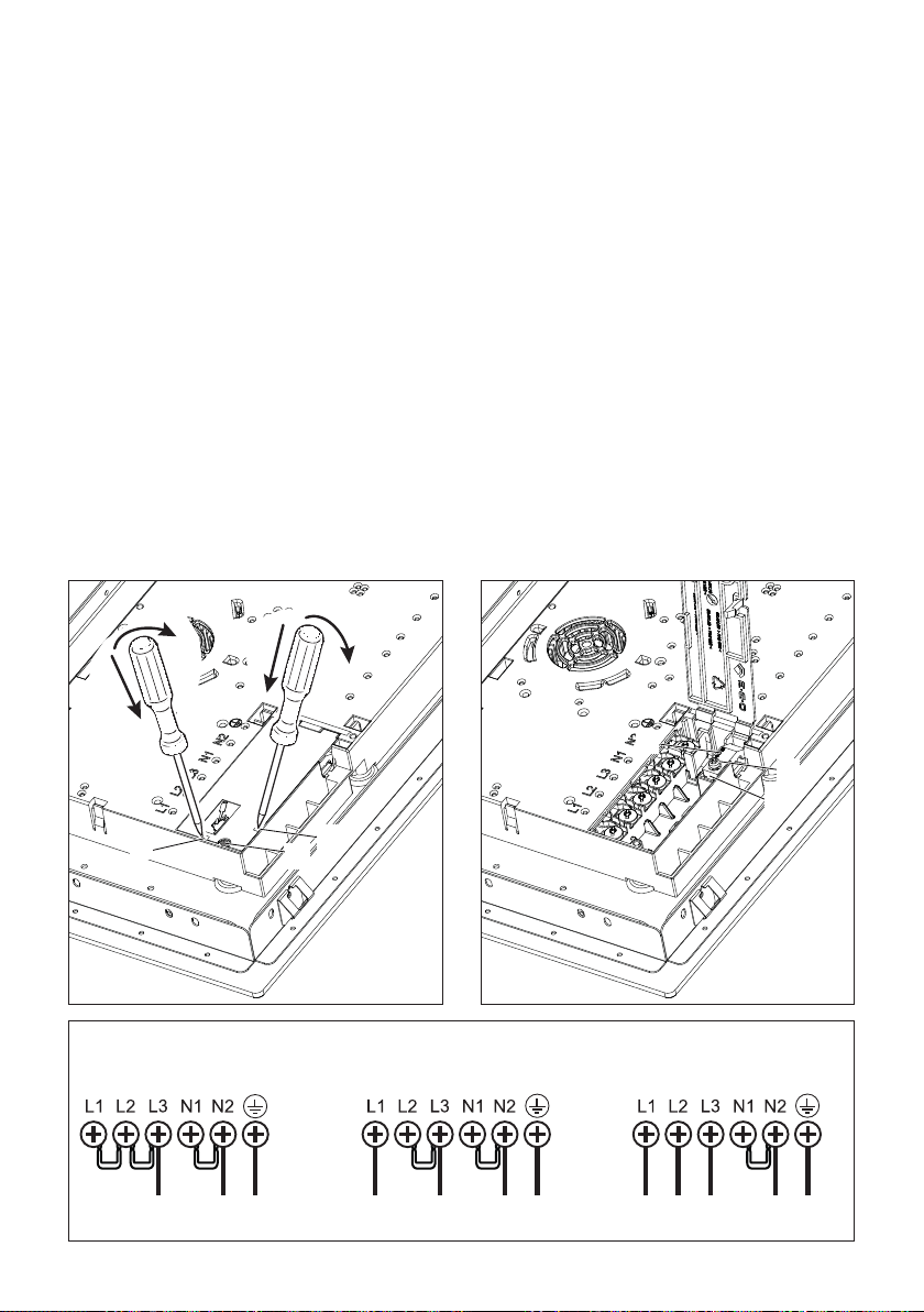
1616
220 - 240 V ac
L N PE
380 - 415 V 2N ac
380 - 415 V 3N ac
L1 L2 N PE L1 L3L2 N PE
Fig. 2.3
1
2
1
2
A
B
B
C
E
D
Fig. 2.1 Fig. 2.2
MODELS SUPPLIED WITH POWER CORD ALREADY FITTED TO THE APPLIANCE
• Connection to the electric power supply must be carried out by a qualied technician
according to the local regulations in force.
• If the supply cord is damaged, it must be replaced by the manufacturer or its
service agent or a similarly qualied person in order to avoid a hazard.
MODELS SUPPLIED WITHOUT POWER CORD ALREADY FITTED TO THE APPLIANCE
• Connection to the electric power supply must be carried out by a qualied technician
according to the local regulations in force.
• Fit a suitable power cord, according to the power rating of the appliance, type:
– H05RR-F, H07RN-F;
– or H05VV-F, H05V2V2-F (resistant to temperatures of 90°C)”.
1717
ATTENTION!
All the operations/electrical connections must be carried out by a qualied technician.
CAUTION!
Do not pierce or weld the terminal ends of the wires. This is strictly forbidden!
CAUTION!
Do not connect the power cord to the electrical power supply without the metallic terminals
correctly in place.
If the supply cord is damaged, it must be replaced by the manufacturer or its service
agent or a similarly qualied person in order to avoid a hazard.
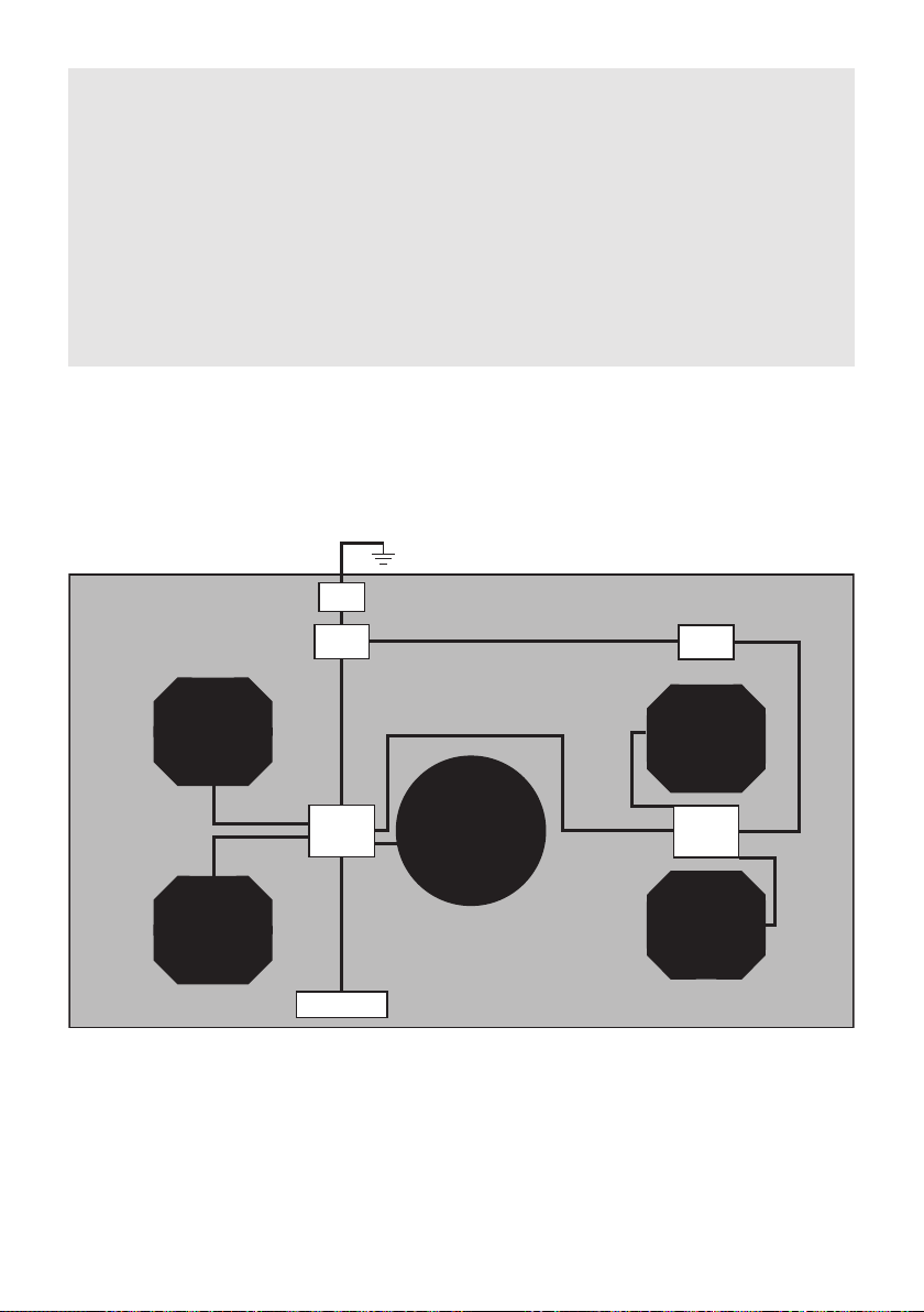
ELECTRIC DIAGRAM
ELECTRIC DIAGRAM KEY
MPB Main power board
PS/FI Power supply/Filter
UI User interface
ID_250 Induction zone Ø250mm
ID_OC Induction ‘Octa’ zone 160x180mm
TB Terminal block
ID_250
MPB
PS/FI
ID_OC
ID_OC
ID_OC
ID_OC
UI
TB
MPB
PS/FI

1818

1919
User guide
2020
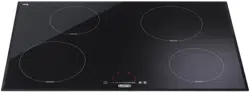
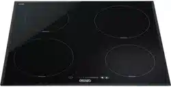
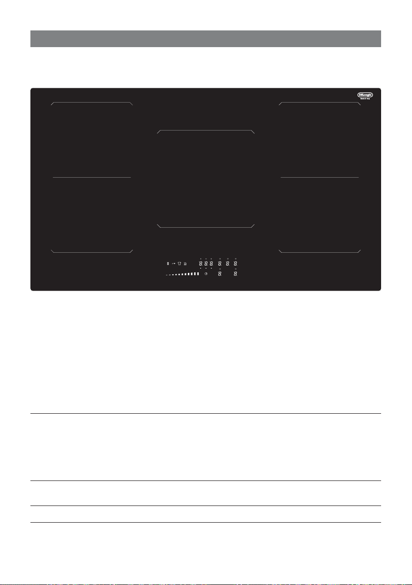
FEATURES AND TECHNICAL DATA
1
Fig. 1.1
1. Induction cooking zone 190 x 210 mm
Normal Power: 2100 W
Booster Power: 2300 W
Double Booster: 3000 W
“Bridge” function: when enabled, the
cooking zones work together as a single
zone - 3700 W.
2. Induction cooking zone Ø 250 mm
Normal Power: 2300 W
Booster Power: 3000 W
3. Touch controls
Note: The Nominal and Booster Power may change depending on the size and material of
the pan set on the cooking zone.
1
1
1
1
2
3
2121
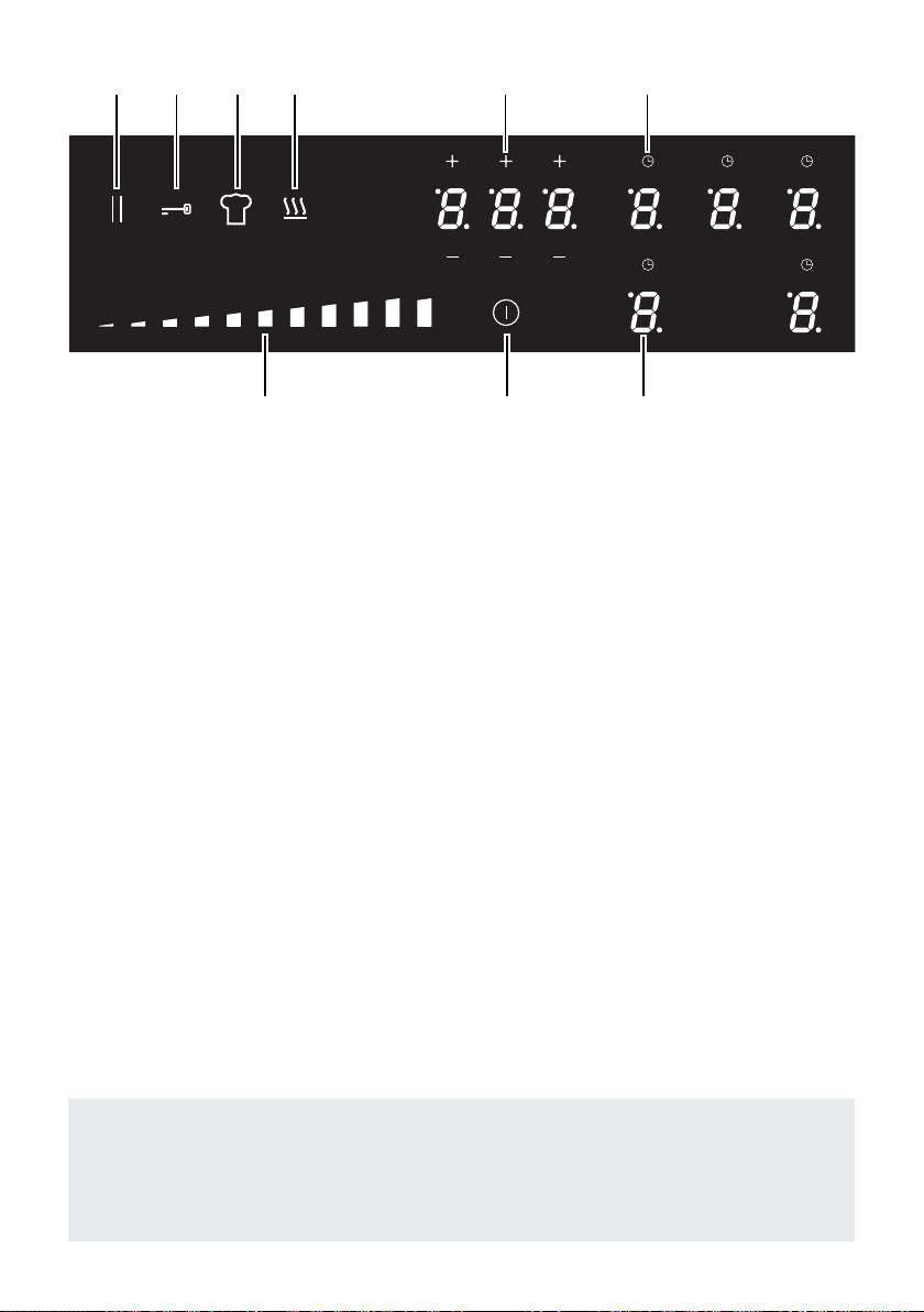
3
TOUCH CONTROLS
1. ON/OFF key
2. Setting selector
3. Pause function key
4. Child lock selection key
5. Chef cook function key
6. Warming function key
7. Automatic cooking (timer) display and keys
8. Selection zone key (one for each zone)
9. Timer key (one for each zone)
Notes:
• Each selection (by touching one of the keys) is indicated by an acoustic signal (beep).
• The touch control area is switched o automatically (and a warning beep sounds for
10 seconds):
– if one or more keys are touched for more than 10 seconds;
– if an object is positioned on the touch control area;
– in the case of spillage of liquids on the control keys.
Fig. 1.2
Attention: Detach the appliance from the mains if the ceramic glass is cracked and
contact the After-Sales Service.
Metallic objects such as knives, forks, spoons and lids should not be placed on the
hob surface since they can get hot.
1 82
3 4 5 6 7 9
2222
The ceramic hob is tted with induction cooking zones.
These zones, shown by painted disks on the ceramic surface, are controlled by a touch
control system.
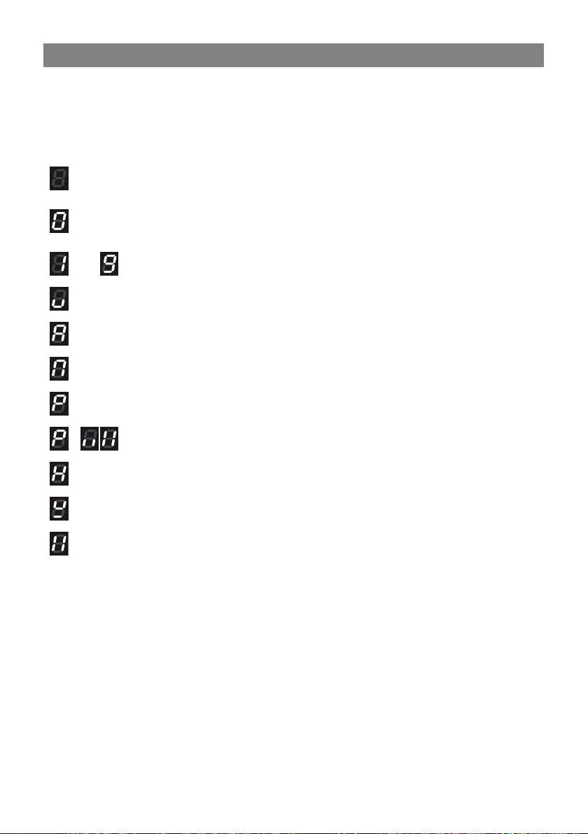
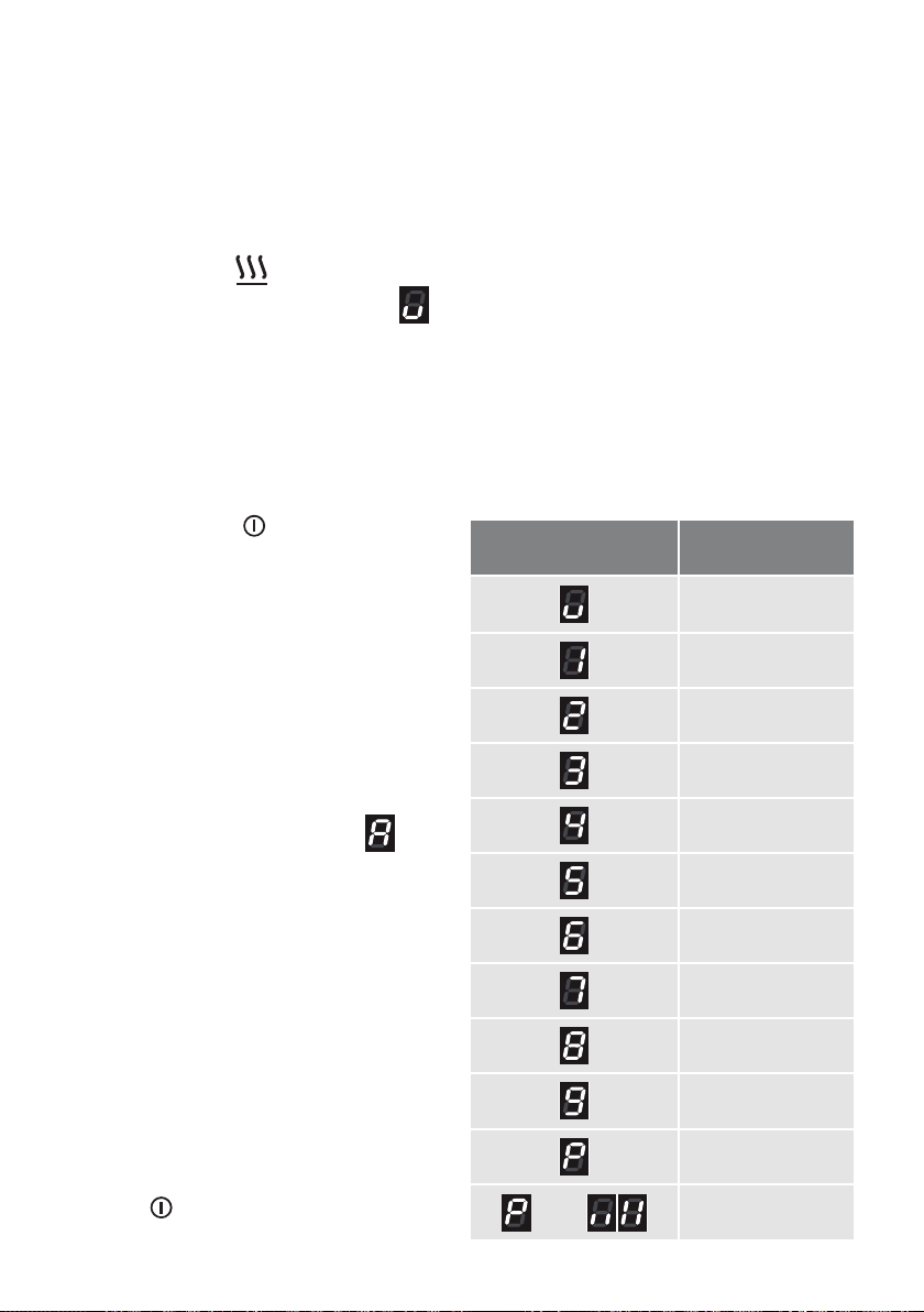
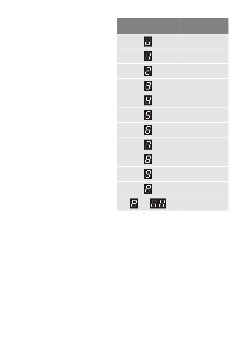
In the front central area of the hob, the displays of the
touch control system
indicate:
USE OF INDUCTION HOB
2
= Cooking zone O (not activated)
= Cooking zone On (activated but not operating).
If all the zones are in zero setting, the touch control system switches o
automatically (touch controls O) after about 20 seconds.
÷
= Power levels
= GentleHeat low setting
= “Fast heating” function
= “Bridge” function
= “Booster” function
= Double “Booster” function (available for some zones only)
= Remaining heat indicator
= Pan detection indicator
= Pause function
Note: Each lit gure refers to the relevant cooking zone.
INDUCTION COOKING SYSTEM
When your induction hob is switched On and a cooking zone has been selected, the
electronic circuits produce induced currents that instantaneously heat the bottom of the
pan which then transfers this heat to the food. Cooking takes place with hardly any energy
loss between the induction hob and the food.
Your induction hob operates only if a correct pan with the right features is placed on a
cooking zone. Please refer to “COOKWARE/COFFEE POT FOR INDUCTION COOKING”.
2323
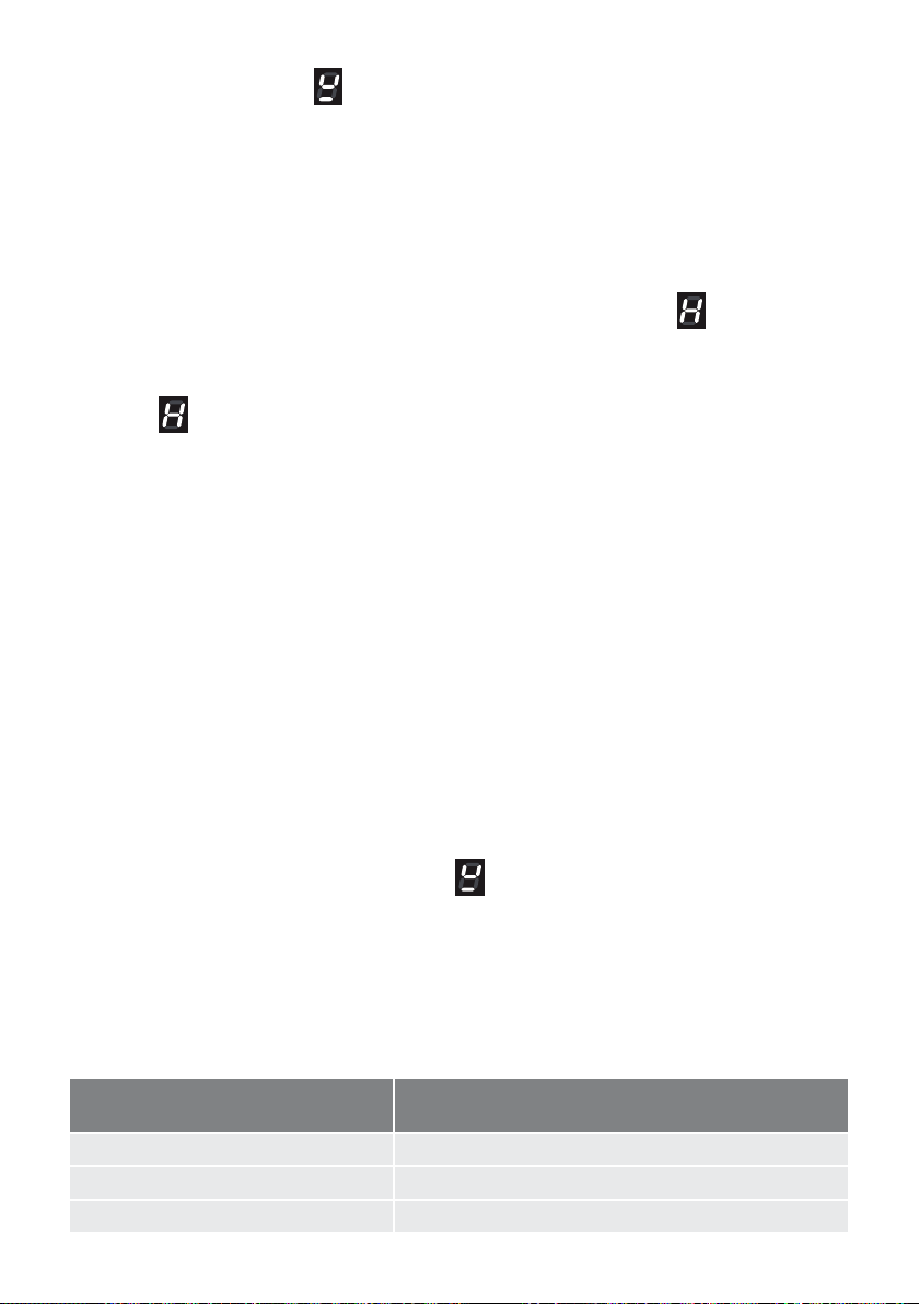
If the pan detection symbol
appears on the display, your pan is not suitable and your
induction hob will not operate. After 10 minutes without detecting any pan, the cooking
zone switches O automatically.
If the induction cooktop emits a humming noise when a zone is used on a high power level,
this phenomenon is normal as it is caused by the induction cooking tecnology.
The noise should weaken or disappear completely when the power level is decreased.
REMAINING HEAT INDICATORS
When the temperature of a cooking zone is still hot, the relevant
remaining heat
indicator lights up on the display to alert you of the hot surface.
Avoid touching the hob surface over the cooking area. Please pay special attention to
children.
When the
is lit on the display, it is still possible to start cooking again; just operate the
cooking zone as indicated in the chapter
POWER IGNITION AND ADJUSTMENT OF A
COOKING ZONE
.
COOKWARE/COFFEE POT FOR INDUCTION COOKING
The induction cooking system OPERATES ONLY if using correct cookware suitable for
induction cooking (normally identied by an induction symbol on the bottom of the cookware/
coee pot). The use of not suitable cookware may cause damage to the appliance.
The bottom of the pan/coee pot has to be ferromagnetic to generate the electromagnetic
eld necessary for the heating process (meaning a magnet has to stick to the bottom of the
pan/coee pot).
Pans/coee pots made from the following materials are not suitable:
• glass, wood, porcelain, ceramic, stoneware;
• pure stainless steel, aluminium or copper without magnetic bottom.
To check if a pan/coee pot is suitable or not:
• Test the bottom of the pan/coee pot with a magnet: if the magnet sticks, the pan is suitable.
• If a magnet is not available pour a small amount of water inside the pan/coee pot and
place the pan on a cooking zone. Switch on the cooking zone: if the cooking zone display
shows alternately the set power level and
, the pan/coee pot is not suitable .
Important: Do not use pots/coee pot adaptors; this could cause an overheating and
possible damage to the appliance.
Important note: the cooking zones will not operate if the pan/coee pot diameter is too
small. To correctly use the cooking zones follow the indications given in the following table.
Induction cooking zone
Minimum pan diameter recommended
(referred to the bottom of the pan)
Cooking zone 190 x 210 mm 110 mm
Cooking zones Bridged 230 mm
Cooking zone Ø 250 mm 130 mm

2424
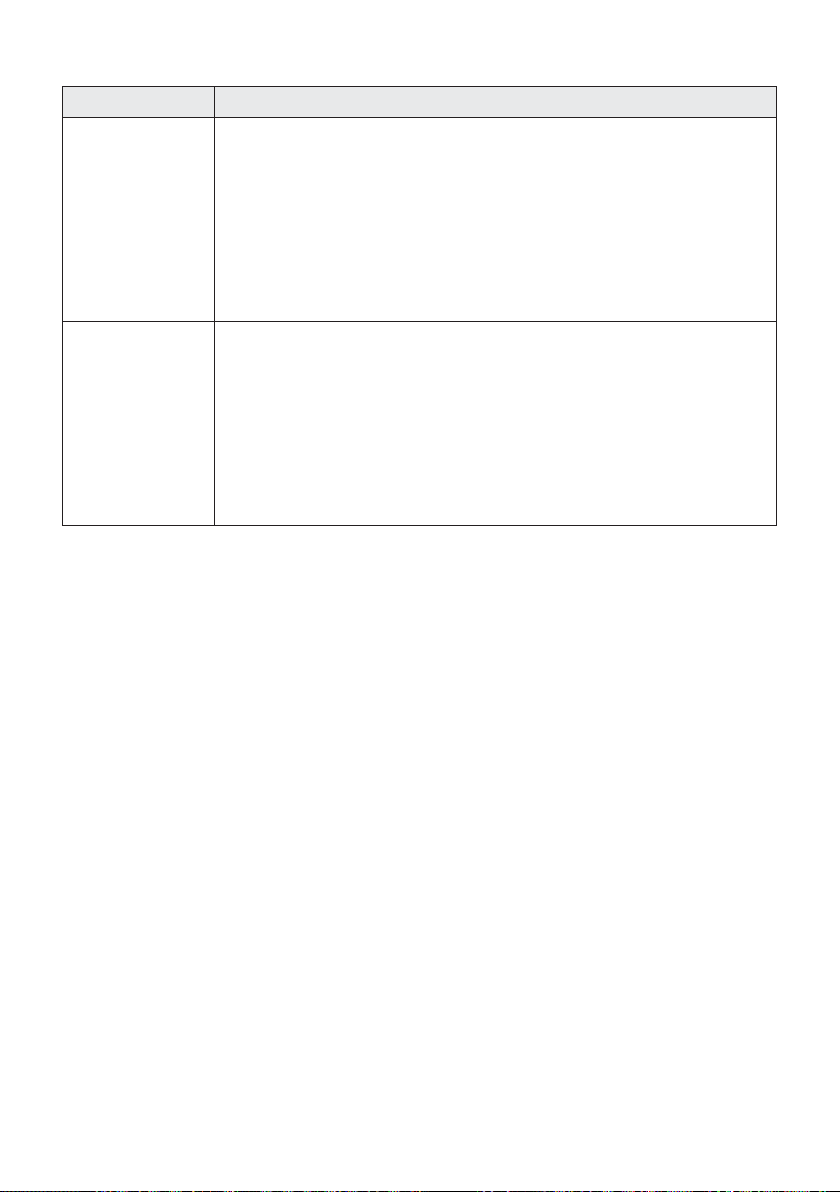
IMPORTANT: Some cookware available on the market has an eective ferromagnetic
area which is much smaller than the diameter of the pan itself. Avoid using this cookware
because the induction cooktop may not function properly or may be damaged.
Pay attention: The pan/coee pot shall always be centred over the middle of the cooking
zone. It is possible to use oversized pans/coee pots but its bottom shall not touch the
other cooking zone.
Always use pans/coee pots with thick, completely at bottom.
Do not use pans/coee pots with concave or convex bottom; these could cause overheating
of the cooking zone.
Note: Some types of pans/coee pots could cause noise when used on an induction
cooking zone.
The noise does not mean any failure on the appliance and does not inuence the cooking
operation.
Always lift pans o the induction hob – do not slide, or they may scratch the glass.
2525
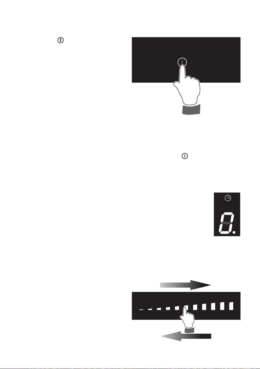
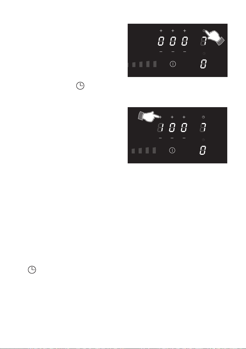
HOW TO SWITCH ON/OFF THE COOKTOP
Switching ON
Touch the key
until the touch control
system is lit (g. 2.1). The displays of
the cooking zones read “ 0. ” or “.”
(depending if a pan is placed or not on
the relative zone).
Notes:
• If the safety Child Lock Safety or Key
Lock Safety is active, the cooktop can
be used only after having deactivated
this protection (see chapter CHILD
LOCK SAFETY and KEY LOCK
SAFETY).
• Auto switch-O: If a cooking zone is
not turned On within 20 seconds, the cooktop will automatically switch o.
Switching OFF
The cooktop may be switched O at any time by pressing the key
.
If any cooking zones are turned On, they will be turned O.
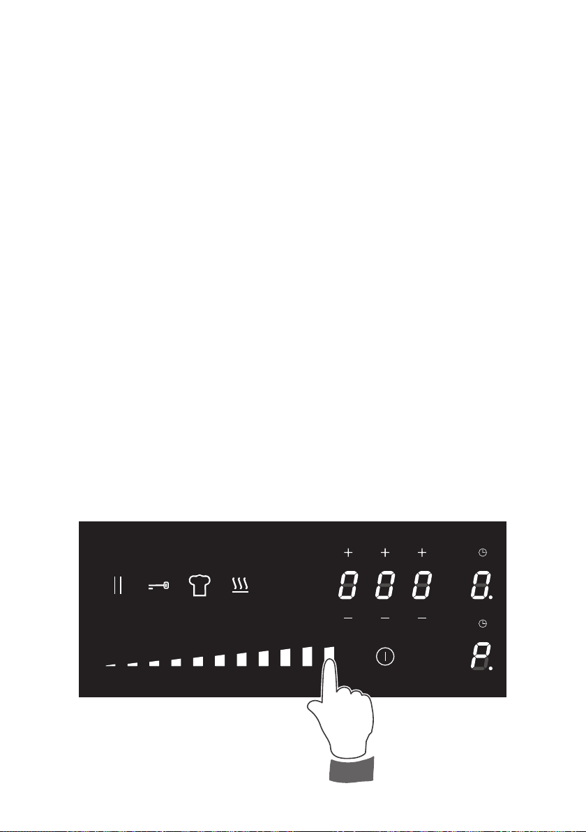
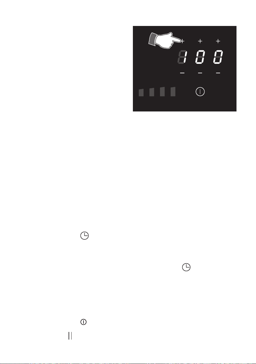
POWER IGNITION AND ADJUSTMENT OF A COOKING ZONE
To turn On a cooking zone the cooktop must be switched On (see section
“HOW TO SWITCH ON/OFF THE COOKTOP”).
• Select a cooking zone by touching the relevant display of the cooking
zone to be used (g. 2.2).
• Select a setting on the selector [between “ 1 ” (minimum) and “ P ”
(maximum)]: touch at one point to “jump” to a specic setting or slide
your nger along the selector (g. 2.3).
• The cooking zone display shows the selected level.
• The power level can be modied at any time.
Increase
Decrease
Fig. 2.1
Fig. 2.2
Fig. 2.3
2626
GENTLEHEAT LOW SETTING (WARMING/MELTING)
This function is ideal for the most delicate cooking tasks (such as melting chocolate), as
the cooking zone will provide a very low continuous gentle heat. It is also ideal for keeping
cooked food warm and the gentle warming of delicate foods.
To turn On a cooking zone the cooktop must be switched On (see section “HOW TO
SWITCH ON/OFF THE COOKTOP”).
• Select a cooking zone by touching the relevant display of the cooking zone to be used.
• Touch the key
.
• The cooking zone display shows
.
“FAST HEATING” FUNCTION
To activate the “Fast Heating” function:
• Press the key
and keep it pressed
until the touch control is lighted.
• Select a cooking zone by touching the
relevant display of the cooking zone to
be used.
• Select a setting on the selector (between
“ 1 ” and “ 8 ”): touch at one point to
“jump” to a specic setting or slide your
nger along the selector (g. 2.3) and
press for several seconds, the operation
is indicated by an acoustic signal (beep).
The cooking zone display alternates
between set power level and
.
This function allows the cooking zone to
operate at the maximum power (100%) for a
time proportional to the selected power level;
after this time the cooking zone will operate
at the selected level.
This function is available on all the cooking
zones.
While this function is operating it is possible,
at any time, to increase the selected power
level but it is not possible to decrease the
power; by touching the selector to a lower
level the function will be disabled.
The function will be disabled also by press
the key
or by selecting the “Booster”
function.
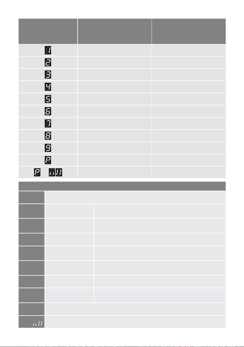
Power level of
Cooking zones
Operation
time limit
function not
available
15 seconds
25 seconds
50 seconds
120 seconds
170 seconds
350 seconds
170 seconds
195 seconds
function not
available
function not
available
and
function not
available
2727
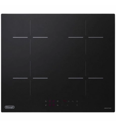
“FULL BRIDGE” FUNCTION (EXTENDABLE MAXI ZONE)
This function can be used to link the two zones (only for induction cooking zone 160 x 180
mm) in “Bridge” mode, to create an extended maxi zone which is ideal for large rectangular
pans or specialist sh cookware.
To enable this function:
• Switch on the hob (see section “HOW TO SWITCH ON/OFF THE COOKTOP”).
• Select both of the two zones by nger pressure (g. 2.4).
• Select the power level [from “ 1 ” (minimum) to “ P ” (maximum)]: touch the desired
power level on the power selector or slide your nger over it (g. 2.3).
• The front cooking zone display will show the heat setting. The rear cooking zone will
show .
• The power level can be changed at any time by selecting front cooking zone (the dot
indicator light of the front zone is lighted) and then setting the new level as described
previously.
• To disable the “Bridge” function repeating the simultaneous selection of both cooking
elements or switching o by key
.
Note: It is not possible to activate the Double Booster function.
Fig. 2.4
2828
BOOSTER FUNCTION
This function allows the cooking zone to operate at the “Booster” maximum power (above
the nominal power) for maximum 5 minutes; it could be used, for example, to rapidly heat
up large amount of water.
To activate the “Booster” function:
• The touch control must be switched ON (see section “How to Turn the Touch Control
ON and OFF”).
• Select a cooking zone by touching the relevant display of the cooking zone to be used.
• Set the power level “P ” for the selected cooking zone, as described in the section
“POWER IGNITION AND ADJUSTMENT OF A COOKING ZONE”. The level “P ”
comes after level “9 ”.
• At the end of the Booster program (5 minutes) the cooking zone is automatically set
to the power level “9 ”.
To deactivate the “Booster” function:
• Set a dierent power level on the selected cooking zone.
or
• Switch O the cooktop.
IMPORTANT NOTES:
• The “Booster” function is not suitable for use with non water based cooking.
• Do not use this function for heating oil (e.g. deep fat frying).
Fig. 2.5

2929
“CHEF COOK” FUNCTION (if this function is not displayed, it means that it is not
available because the hob is set at a too low maximum power level).
This function allows the zone to be ready to use at preset power levels for a maximum of
2 hours.
This means that, once selecting the “Chef Cook” function, each zone is ready in standby
and as soon as placing a suitable pan on it, it is possible to start cooking (pan detection
symbol is not active).
The preset power levels can be modied at any time (following the same procedure for the
power adjustment of a cooking zone) once the “Chef Cook” function is operating. They are
automatically saved for the next use of this function. They are shown on the zone displays
when starting the “Chef Cook” function.
• To activate the “Chef Cook” function press the key
(brightness of key becomes
higher).
• To deactivate the “Chef Cook” function press again the key .
DOUBLE BOOSTER FUNCTION
The Double Booster function allows more power to be supplied compared to the Booster
function.
To activate the “Double Booster” function:
Follow the same procedure as per booster function, then touch again the last level from the
right on the setting selector (the display shows
and alternating).
To deactivate the double “Booster” function:
• Set a dierent power level on the selected cooking zone.
or
• Switch O the cooktop.
– This function is NOT available on the cooking zone Ø 250 mm and when the
“Bridge” function is operating.
IMPORTANT NOTES:
• The “Double Booster” function is not suitable for use with non water based
cooking.
• Do not use this function for heating oil (e.g. deep fat frying).
3030
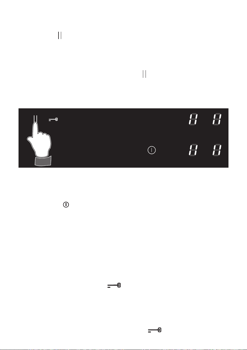
PAUSE MODE
When at least one cooking zone is in operation, the cooking may be paused temporarily by
touching the key
(g. 2.6).
Already programmed automatic cookings are stopped and do not continue during the
pause.
The residual heat calculation and operating time limitation continue and are not stopped.
The pause mode may last for max 10 minutes. If the pause mode is not terminated within
the time, the cooktop switches O automatically.
To deactivate the pause mode touch again the key
and then touch any cooking zone
display.
The cooktop may be switched O at any time with the On/O key; any possibly program
already set (pause mode included) is then terminated.
KEY LOCK SAFETY
This function locks the touch-control keys against unwanted activation e.g. while cleaning.
To activate the key-lock press the key
; the brightness becomes high to indicate that
the safety key-lock is active.
• Cooking zone/s operating (power level already set): with the key-lock protection active
it is only possible to switch o the cooktop.
• Cooktop o: with the key-lock protection active it is not possible to use the cooktop. To
use the cooktop deactivate this protection.
To deactivate the key-lock protection just press the key
.
Fig. 2.6
CHILD LOCK SAFETY
When not using the induction hob, set the Child Lock safety to prevent children from
accidentally switching On the cooking zones.
• Ensure all cooking zones are switched O.
• Touch the key
until the touch control system is lit.
• Touch any cooking zone for 3 seconds. The slider area shows a chaser light sequence.
• Slide your nger along the selector from “ 1 ” (minimum) to “ 9 ” (maximum) within 10
seconds (before starting to slide, keep the nger in position “ 1 ” for about one second).
“ L ” lights up.
• To deactivate the Child Lock, touch any cooking zone for three seconds and slide your
nger along the selector from “ 9 ” (maximum) to “ 1 ” (minimum) within 10 seconds
(before starting to slide, keep the nger in position “ 9 ” for about one second)
until “ 0 ”
or “.” lights up on the displays of the cooking zones.
3131
OPERATION TIME LIMIT OF
THE COOKING ZONES
Each cooking zone is automatically
switched O after a maximum preset
time if no operation is performed.
The maximum preset time limit
depends on the set power level, as
illustrated in this schedule.
Each operation on the cooking hob by
using the touch controls will reset the
maximum operation time at its initial
value.
POWER LEVEL OF
COOKING ZONES
OPERATION
TIME LIMIT
120 minutes
360 minutes
360 minutes
300 minutes
300 minutes
240 minutes
90 minutes
90 minutes
90 minutes
90 minutes
5 minutes
and
5 minutes
3232
EXAMPLES OF COOKING POWER SETTING
0
Cooking zone not operating
1 to 2
Melting
Reheating
Sauces, butter, chocolate, gelatine
Dishes prepared beforehand
2 to 3
Simmering
Defrosting
Rice, pudding, sugar syrup
Dried vegetables, sh, frozen products
3 to 4
Steam Vegetables, sh, meat
4 to 5
Water
Steamed potatoes, soups, pasta,
fresh vegetables
6 to 7
Medium cooking
Simmering
Meat, lever, eggs, sausages
Goulash, roulade, tripe
7 to 8
Cooking Potatoes, fritters, wafers
9
Frying, roasting
Boiling water
Steaks, omelettes, fried dishes
Water
P
Rapidly heat up large amount of water
P and
Rapidly heat up large amount of water at the maximum power
COOKING
ZONE
POWER
LEVEL
COOKING
ZONE
Ø 250 mm
(Watt power)
COOKING
ZONE
160 x 180 mm
(Watt power)
75 60
120 105
180 165
270 255
420 375
645 585
960 885
1470 1320
2295 2100
3000 2300
and
not available 3000
3333
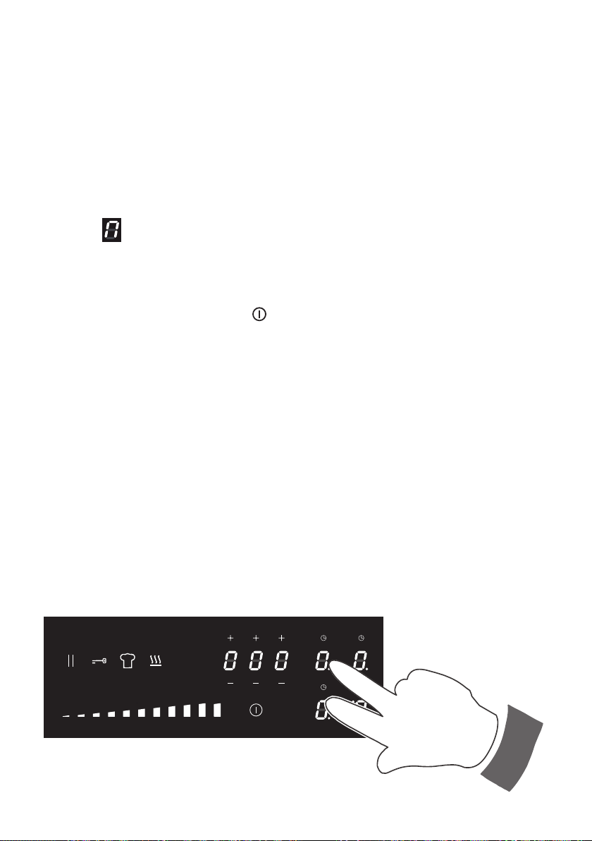
PROGRAM FOR AUTOMATIC
SWITCHING OFF OF A COOKING
ZONE
This function permits to set a timer from “1 ”
minute to “9 ” hours and “ 59 ” minutes for
automatic turning O the cooking zone/s.
With the cooktop switched On:
• Select the cooking zone and set the
desired power level.
• Touch the timer key
(the timer key
and the display of cooking timer starts
blinking).
• Within 10 seconds set the timer using
the + and - buttons to select the
required time (the rst digit on the left
is used to select the hours, the middle
one to set the tens of minutes and the
one on the right the minutes).
• The program is now processed (the
timer key indicating the programmed
zone steady lit).
• The time can be changed at any time
following the same procedure here
above indicated.
• To program another cooking zone,
repeat as described above.
Now the program for automatic switching
O is complete.
At the end of the countdown the cooking
zone will switch O automatically, an
acoustic signal (beep) will sound (for 2
minute only), and “ 0.00 ” will ash on the
timer display.
Touch one of the keys to stop the beep.
The program for automatic switch O can be
cancelled at any time by touching
the timer
key for 3 seconds.
IMPORTANT: Remember to switch O the
zone manually.
Fig. 2.7
Fig. 2.8
3434
MINUTE COUNTER
The minute counter is a timed acoustic
warning device which can be set from “1 ”
minute to “9 ” hours and “ 59 ” minutes.
With the cooktop switched On:
• Touch the timer display (the display
starts blinking).
• Within 10 seconds set the timer using the
+ and - keys to select the required time
(rst digit from the left = hours, second
and third digit from the left = minutes,
each single digit can be adjusted
individually).
At the end of the countdown, an acoustic
signal (beep) will sound (for 2 minute only),
and “ 0.00 ” will ash on the timer display.
Touch one of the keys to stop the beep.
IMPORTANT: Remember to switch O the
zones manually.
COUNT UP
This function starts an incremental count and it can be activated for each single zone when
it is in operation.
It can be used e.g. to control how long the cooking has been in progress.
With the cooktop switched On:
• Select the cooking zone and set the desired power level.
• Touch the timer key
(above the relative zone) for 3 seconds (an acoustic signal,
beep, will sound).
• The count up is visible for the rst 10 seconds, then it is hidden. To show it again, for
10 seconds, touch the cooking zone display.
The count up can be cancelled at any time by touching
the timer key for 3 seconds (the
display reads “ 0.00 ”).
RECALL FUNCTION
This function can be used when the cooktop is switched O unintentionally during the use
(e.g. by touching the key
).
In this case, by switching On the cooktop again within 6 seconds and by touching
immediately the key , it is possible to restart the the cooking with all the previous settings
before the switching O.
Fig. 2.9
3535
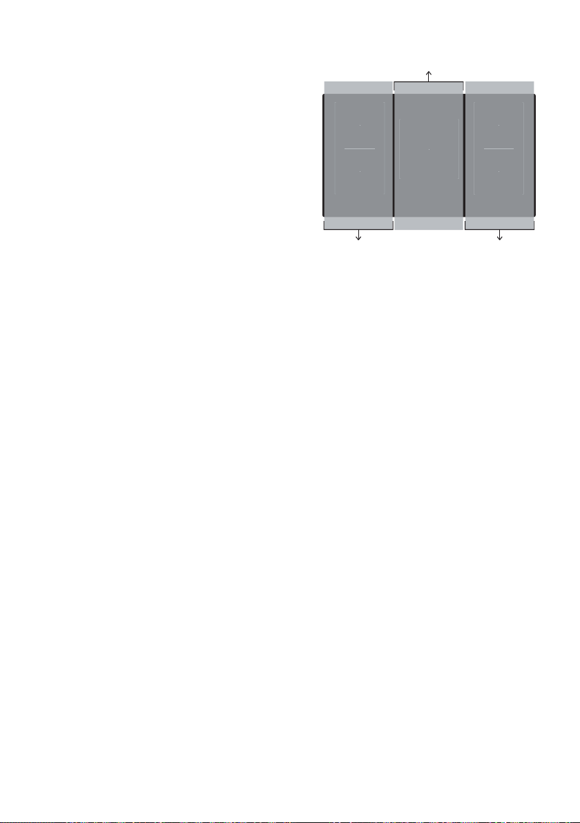
MAXIMUM USABLE POWER FOR THE
COOKING ZONES
The cooking zones are controlled by 3 separate
power boards:
The maximum total power per each power
board is 3700 W.
Should the cooking zones of one power board
require more than 3700 W, the last selected
power level has priority and the power of the
other cooking zone is automatically reduced to
the remaining power available.
If this occurs, the cooking zone will display
a ashing gure for about 3 seconds before
automatically displaying the new power level.
This means for example that:
• When setting a “Booster” programme for
the second zone, the setting for the other
zone could be reduced to the remaining
power available.
• When setting a “Booster” programme for
a zone and then another setting on the
second zone, if the total power exceed
3700 W the “Booster” programme is
deleted and the power reduced to the
maximum power available.
THERMAL PROTECTIONS
The induction hob is tted with safety devices
to protect the electronic system and to protect
each cooking zone from overheating.
In case of overheating, one of the following
automatic functions could be started by the
electronic system:
• “Booster” program deleted and power
reduced.
• One or more cooking zone switched O.
• Cooling fan motor of the induction unit
switched On.
Fig. 2.10
Controlled by
1st power board
Controlled by
2nd power board
Controlled by
3rd power board
3636
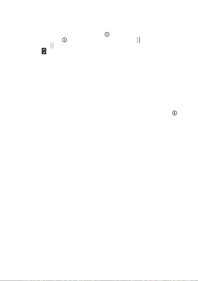
USER MENU
With the user menu it is possible to customize some features as described in table 9.1.
To access the User Menu:
• Switch On the cooktop by touching the key
.
• Touch the key again
and keep it pressed until the symbol starts blinking.
• Touch the key
and keeping it pressed touch, one at a time, the selecting zone keys
(showing
) starting from the front-left zone key and then proceeding in clockwise
order until touching all the zone keys.
• In the rear selection zone key each menu option is indicated, on the display, with the letter
“U ” alternating with a number (see table 9.1). The setting of each option is indicated in
the front selection zone key or in the timer display.
– To change the menu option, touch the rear selection zone key (where “U ” alternates
with a number) and then use the setting selector to choose another option (each
selector bar is assigned to an option).
– To change the setting of each option, touch the front zone selection key (or the timer
display for the maximum power management “U0 ” only) and then modify the setting
by using the setting selector (depending on the option being customized, only some
bars may be operative).
• Once completing the customization, switch O the cooktop by touching the key .
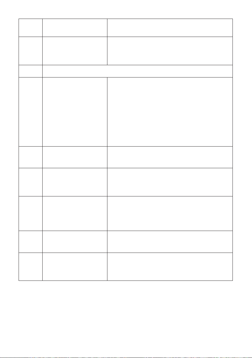
3737
Menu
Option
Description Remark
U0
Maximum power
management
To change the setting, use the setting selector by
touching the left bar to decrease or the right bar
to increase (see also chapter MAXIMUM POWER
MANAGEMENT following).
U1
This option is not available in your model.
U2
Beeps volume (when
touching a selection key)
Adjustment settings:
0: no beeps
1: min. volume
2: mid. volume
3: max. volume
Notes:
• For safety reasons, the Beeps when switching
On and O cannot be disabled.
• Beeps for errors are always at max. volume and
cannot be disabled.
U3
Acoustic signal volume
(e.g. after a programmed
cooking)
Adjustment settings as per U2.
U4
Display brightness Adjustment settings:
0: Max. brightness
....
9: Min. brightness
U5
Timer digits animation
(segments of the
numbers fully
displayed or displayed
progressively)
Adjustment settings:
0: No animation
1: Animation
U6
Automatic pot detection
(shows if there is a pot or
not on a cooking zone)
Adjustment settings:
0: Pot detection not active
1: Pot detection active
U7
Duration of acoustic
signal (e.g. after a
programmed cooking)
Adjustment settings:
0: 120 secs
1: 10 secs
2: No signal
3838
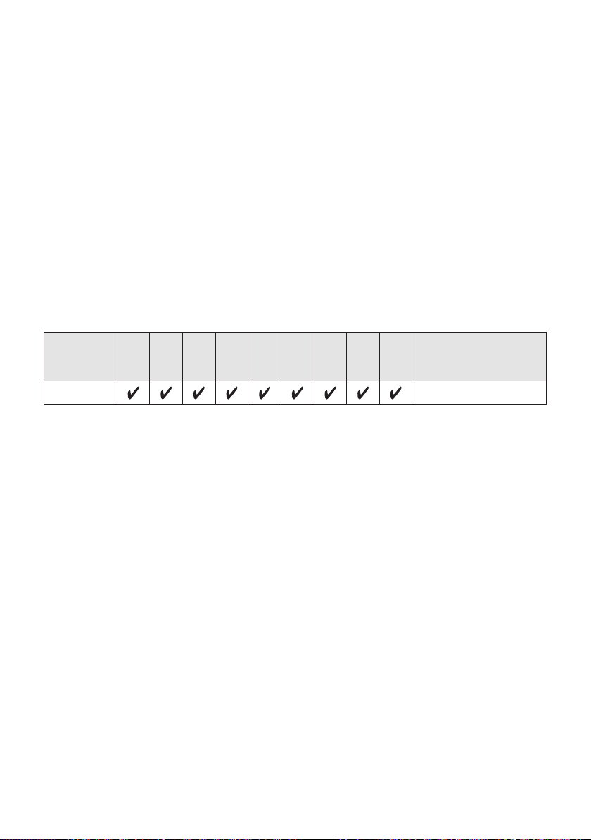
MAXIMUM POWER MANAGEMENT
Depending on the specic market requirements, the product is supplied with a maximum
power (factory setting) as indicated on the rating label (see possible options in table below).
The maximum power can be modied in any time (100W steps) by accessing the User
Menu, option “U0 ” (see chapter USER MENU).
IMPORTANT:
• It is only possible to decrease (NOT increase) the power with respect to the maximum
factory setting.
• If the cooktop is already set in factory to the minimum power level, it is not possible to
carry out any modication.
• The maximum power setting can be checked in any time by accessing the User Menu,
option “U0 ” (see chapter USER MENU).
For the models factory-set at the maximum higher power (last column of the table here
below), the display doesn’t show the total power of the cooktop but the total power for
each power board.
Models
1,4
kW
2
kW
2,5
kW
2,8
kW
3
kW
3,5
kW
4
kW
5
kW
6
kW
Maximum higher
power (kW) referred to
each power board
90cm wide
3,7 x 3 power boards
POWER MANAGEMENT WHEN USING THE COOKTOP
Should the cooking zones of one power board require more than the maximum total
power, the last selected power level has priority and the power of the other cooking zone
is automatically reduced to the remaining power available (or switched o if there is not
enough power available).
If this occurs, the cooking zone will display a ashing gure for about 3 seconds before
automatically displaying the new power level.
3939
Error code What to do
Erxx
or
display
not operative
1. Switch O the cooktop and disconnect it from the mains.
2. Wait for about 1 minute, then reconnect the cooktop and turn on
the cooking zones.
3. Wait for about 1 minute and if the error message does not appear
again the cooking zones can be used.
4. If the error message does not disappear repeat step from 1 to 3.
5. If the problem continues do not use the induction hob and contact
your Authorised Service Centre.
Er03
1. Permanent activation of the controls area. e.g. an object
positioned on the touch controls or a liquids spillage on the
controls area.
2. Please remove the object or dry the liquids.
ERROR CODES ON THE DISPLAYS OF THE COOKING ZONES
4040
SAFETY HINTS
• Before switching on make sure that
you have the correct cooking zone for
the hotplate chosen. It is advisable
to put the pan on the hotplate before
switching on and to take it away after
switching o.
• Use correct cookware suitable for
induction cooking (normally identied
by an induction symbol on the bottom).
The use of not suitable cookware may
cause damage to the appliance.
• Use cookware with at and even
bottoms. Uneven bottoms can scratch
the glass ceramic surfaces. Be careful
that the bottom is clean and dry.
• To save electricity, use pan lids
whenever possible.
• Do not leave wet or damp lids on the
hob.
• Make sure that the handles of
cookware do not stick out over the
edge of the hob, to avoid them being
knocked over by accident. This also
makes it more dicult for children to
reach the cooking vessels.
• Do not put aluminium foil or plastic
objects on the cooking zones when
they are hot.
• Do not lean over the cooking zones
when they are switched on.
• The glass-ceramic surface and pans
must be clean. Carefully eliminate any
food remains (especially containing
sugar), dirt etc. with the aid of a
cleansing agent.
• Follow the cleaning instructions
carefully.
• Do not use the hob if the glass
surface is broken or cracked in any
way. Please disconnect the hob
from the mains and contact the
After-Sales Service.
• Never use the glass surface for
storage.
DO NOT USE PANS WITH ROUGH
CIRCULAR MACHINED BASE.
Fig. 2.11
Fig. 2.12

4141
CLEANING AND MAINTENANCE
3
GENERAL ADVICE
• Before you begin cleaning, you must ensure that the appliance is switched o
and disconnected from the electrical power supply.
• It is advisable to clean when the appliance is cold.
• Avoid leaving alkaline or acidic substances (lemon juice, vinegar, etc.) on the surfaces.
• Avoid using cleaning products with a chlorine or acidic base.
• Do not use a steam cleaner because the moisture can get into the appliance thus
make it unsafe.
• Important: The use of suitable protective clothing/gloves is recommended when
handling or cleaning of this appliance.
• Do not scratch the cooktop with cutting or sharp objects.
• Important: The manufacturer declines all liability for possible damage caused by
the use of unsuitable products to clean the appliance.
• Clean surfaces with a damp cloth and use gentle, neutral cleaning products. Dry with
a clean, dry cloth.
• IMPORTANT: Do not use any abrasive products (e.g. certain types of sponge) and/
or aggressive products (e.g. caustic soda, products containing corrosive substances),
which could cause irreparable surface damage.
WARNING!
When correctly installed, your product meets all safety requirements laid down for
this type of product category. However special care should be taken around the
underneath of the appliance as this area is not designed or intended to be touched
and may contain sharp or rough edges, that may cause injury.
4242
CLEANING THE CERAMIC HOB
• Remove spillages and other types of incrustations.
• Dust or food particles can be removed with a damp cloth.
• If you use a detergent, please make sure that it is not abrasive or scouring. Abrasive
or scouring powders can damage the glass surface of the hob.
• All traces of the cleaner must be removed with a damp cloth.
• Dust, fat and liquids from food that has boiled over must be removed as soon as
possible. If they are allowed to harden they become increasingly dicult to remove.
This is especially true in the case of sugar/syrup mixtures which could permanently pit
the surface of the hob if left to burn on it.
• Do not put articles on the hob which can melt: i.e plastic, aluminium foil, sugar, sugar
syrup mixtures etc.
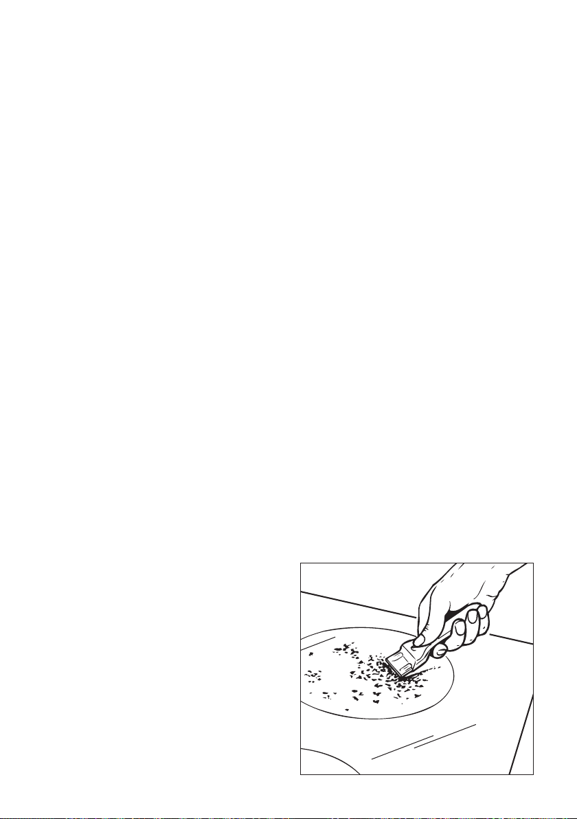
• If any of these products has melted on the ceramic surface, you should remove it
immediately (when the surface is still hot) by using a proper scraper to avoid any
permanent damage to the surface of the hob.
• Avoid using a knife or other sharp utensil as these may damage the ceramic surface.
• Do not use steel wool or an abrasive sponge which could scratch the surface
permanently.
STAINLESS STEEL ELEMENTS (only models with side stainless steel trims)
Stainless steel parts must be rinsed with water and dried with a soft and clean cloth.
For persistent dirt, use specic non-abrasive products available commercially or a little
hot vinegar.
Fig. 3.1

4343
SERVICE AND MAINTENANCE
Servicing the appliance:
Service may be obtained by contacting our Customer Service Centre to locate the nearest
Authorised ELBA APPLIANCES Service Agent shared services with Fisher and Paykel
Australia PTY LTD (ELBA Appliances AUS, a division of F&P AUS PTY LTD).:
Servicing shall be carried out only by authorized personnel.
The appliance shall not be modied.
TROUBLESHOOTING
If you acquire a problem with your hob, check the following points before calling an engineer.
1. The power is switched on.
2. The controls are switched on.
3. Both the fuse and the mains fuse are intact.
Should you still require assistance please contact our Customer Service Centre for your
nearest Authorised Elba Appl. AUS Service Agent..

Cod. 1106337 - ß1
Descriptions and illustrations in this booklet are given as simply indicative.
The manufacturer reserves the right, considering the characteristics of the
models described here, at any time and without notice, to make eventual necessary
modifications for their construction or for commercial needs.
www.delonghicookingappliances.com.au