Husqvarna
02139
Owner's Manual
SAFETY RULES
A A
IMPORTANT: THiS CUTTING MACHINE iS CAPABLE OF AMPUTATINGHANDS AND FEETAND THROWING OBJECTS. FAILURE
TO OBSERVE THE FOLLOWING SAFETY iNSTRUCTiONS COULD RESULT iN SERIOUS iNJURY OR DEATH.
L GENERAL OPERATmON
o Read, understand, and follow all instructions in the
manual and on the machine before starting,
o Only allow responsible adults, who are familiar with the
instructions, to operate the machine,
Clear the area of objects such as rocks, toys, wire, etc,,
which could be picked up and thrown by the blade,
Be sure the area is clear of other people before mow-
ing, Stop machine if anyone enters the area,
Never carry passengers,
Do not mow in reverse unless absolutely necessary, AF
ways look down and behind before and while backing,
o Be aware of the mower discharge direction and do not
point it at anyone, Do not operate the mower without
either the entire grass catcher or the guard in place,
Slow down before turning,
Never leave a running machine unattended, Always
turn off blades, set parking brake, stop engine, and
remove keys before dismounting,
Turn off blades when not mowing,
Stop engine before removing grass catcher or un-
clogging chute,
o Mow only in daylight or good artificial light,
o Do not operate the machine while under the influence
of alcohol or drugs,
o Watch for traffic when operating near or crossing road-
ways,
Use extra care when loading or unloading the machine
into a trailer or truck,
Data indicates that operators, age 60 years and above,
are involved in a large percentage of riding mower-re-
lated injuries, These operators should evaluate their
ability to operate the riding mower safely enough to
protect themselves and others from serious injury,
Keep machine free of grass, leaves or other debris
build-up which can touch hot exhaust / engine parts
and burn, Do not allow the mower deck to plow leaves
or other debris which can cause build-up to occur,
Clean any oil or fuel spillage before operating or
storing the machine, Allow machine to cool before
storage,
H. SLOPE OPERATmON
Slopes are a major factor related to loss-of-control and
tipover accidents, which can result in severe injury or death,
All slopes require extra caution, if you cannot back up the
slope or if you feel uneasy on it, do not mow it,
DO:
Mow up and down slopes, not across,
Remove obstacles such as rocks, tree limbs, etc,
Watch for hobs, ruts, or bumps, Uneven terrain could
overturn the machine. Tall grass can hide obstacles.
o Use slow speed. Choose a low gear so that you will
not have to stop or shift while on the slope.
Follow the manufacturer's recommendations for wheel
weights or counterweights to improve stability.
o Use extra care with grass catchers or other attachments.
These can change the stability of the machine.
Keep all movement on the slopes slow and gradual
Do not make sudden changes in speed or direction.
o Avoid starting or stopping on a slope, if tires lose trac-
tion, disengage the blades and proceed slowly straight
down the slope.
DO NOT:
o Do not turn on slopes unless necessary, and then,
turn slowly and gradually downhill, if possible.
o Do notmow near drop-offs, ditches, or embankments.
The mower could suddenly turn over if a wheel is over
the edge of a cliff or ditch, or if an edge caves in.
Do not mow on wet grass. Reduced traction could
cause sliding.
o Do not try to stabilize the machine by putting your foot
on the ground.
Do not use grass catcher on steep slopes.
HL CHILDREN
Tragic accidents can occur if the operator is not alert to
the presence of children, Children are often attracted to
the machine and the mowing activity. Never assume that
children will remain where you last saw them.
Keep children out of the mowing area and under the
watchful care of another responsible adult.
o Be alert and turn machine off if children enter the
atea.
• Before and when backing, look behind and down for
small children.
Never carry children. They may fall off and be seriously
injured or interfere with safe machine operation.
o Never allow children to operate the machine.
Use extra care when approaching blind corners, sh rubs,
trees, or other objects that may obscure vision.
mVoSERVICE
o Use extra care in handling gasoline and other fuels,
They are flammable and vapors are explosive,
Use only an approved container,
Never remove gas cap or add fuel with the engine
running, Allow engine to cool before refueling, Do
not smoke,
Never refuel the machine indoors,
Never store the machine or fuel container inside where
there is an open flame, such as a water heater,
Never run a machine inside a closed area,
Keep nuts and bolts, especially blade attachment bolts,
tight and keep equipment in good condition,
o Never tamper with safety devices, Check their proper
operation regularly,
Keep machine free of grass, leaves, or other debris
build-up, Clean oil or fuel spillage, Allow machine to
cool before storing,
Stop and inspect the equipment if you strike an object,
Repair, if necessary, before restarting,
Never make adjustments or repairs with the engine
o Grass catcher components are subject to wear, dam-
age, and deterioration, which could expose moving
parts or allow objects to be thrown. Frequently check
components and replace with manufacturer's recom-
mended parts, when necessary.
o Mower blades are sharp and can cut. Wrap the blade(s)
or wear gloves, and use extra caution when servicing
them.
o Check brake operation frequently. Adjust and service
as required.
2

SAFETY RULES
SAFEOPE.AT,O.P.ACT,CESFO..,DE-O.MOWE.S
@@@@@
,, Be sure the area is clear of other people before mowing. Stop
machine if anyone enters the area.
,, Never carry passengers or children even with the blades
off.
,, Do not mow in reverse unless absolutely necessary. Always
look down and behind before and while backing.
,, Never carry children.They may fall off and be seriously injured
or interfere with safe machine operation.
,, Keep children out of the mowing area and under the watchful
care of another responsible adult.
,, Be alert and turn machine off if children enter the area.
,, Before and when backing, look behind and down for small
children.
,, Mow up and down slopes (15 ° Max), not across.
,, Remove obstacles such as rocks, tree limbs, etc.
,, Watch for holes, ruts, or bumps. Uneven terrain could overturn
the machine. Tall grass can hide obstacles.
,, Use slow speed. Choose a low gear so that you will not have
to stop or shift while on the slope.
,, Avoid starting or stopping on a slope. If tires lose traction,
disengage the blades and proceed slowly straight down the
slope.
,, If machine stops while going uphill, disengage blades, shift
into reverse and back down slowly.
,, Do not turn on slopes unless necessary, and then, turn slowly
and gradually downhill, if possible.
WARNING: in order to prevent ac-
cidental starting when setting up,
transporting, adjusting or making
repairs, always disconnect spark
plug wire and place wire where it
cannot contact spark ptug.
WARNING: Do not coast down a hill
in neutral you may tose control of
the tractor.
WARNING: Tow onJy the attachments
that are recommended by and com-
ply with specifications of the manu-
facturer of your tractor. Use common
sense when towing. Operate onJy at
the lowest possiMe speed when on a
stope. Too heavy of a Joad, while on
a sJope, is dangerous. Tires can Jose
traction with the ground and cause
you to tose controJ of your tractor.
& &
Engine exhaust, some of its constituents, and cer-
tain vehicte components contain or emit chemicals
known to the State of California to cause cancer and
birth defects or other reproductive harm.
A wAR.u.GA
Battery posts, terminaJs and reJated accessories
contain tead and Jead compounds, chemicaJs known
to the State of CaJifornia to cause cancer and birth
defects or other reproductive harm. Wash hands
after handling.

PRODUCT SPECiFiCATiONS
Gasoline Capacity 5 Gallons
and type: Unleaded Regular
Oil Type (APFSG-SL): SAE 10W30 (above 32°F)
SAE 5W-30 (below 32°F)
Oil Capacity: W/FiIter: 4.0 Pints
W/O Filter: 3,5 Pints
Spark Plug: Champion
(Gap: ,030") RC12YC
Ground Speed (MPH): Forward: 0 - 5,8
Reverse: 0 - 2,1
Tire Pressure: Front: 14 PSI
Rear: 10 PSI
Charging System: 15 AMPS @ 3600 RPM
Battery: AMP/HR: 35
MIN, CCA: 280
CASE SIZE: U1R
Blade Bolt Torque: 45-55 FT, LBS,
CUSTOMER RESPONSiBiLiTiES
Road and observe the safety ruUes,
Follow a reguUar scheduUe in maintaining, caring for
and using your tractor,
Follow the instructions under"Maintenance" and "Stor-
age" sections of this owner's manual
WARNING: This tractor is equipped with an internaUcom-
bustion engine and shouUd not be used on or near any
unimproved forest-covered, brush-covered orgrass-covered
UandunUess the engine's exhaust system is equipped with
a spark arrester meeting applicable local or state laws (if
any), If a spark arrester is used, it should be maintained
in effective working order by the operator,
A spark arrester for the muffler is available through your
nearest authorized service centre/department (See RE PAlR
PARTS section of this manual),
CONGRATULATIONS on your purchase of a new tractor, it has been designed, engineered and manufactured to give
you the best possible dependability and performance,
Should you experience any problem you cannot easily remedy, please contact your nearest authorized service center/
department We have competent, well-trained technicians and the proper tools to service or repair this tractor,
Please read and retain this manual, The instructions will enable you to assemble and maintain your tractor properly, Al-
ways observe the "SAFETY RULES",
TABLE OF CONTENTS
SAFETY RULES ......................................................... 2-3
PRODUCT SPECIFICATIONS ....................................... 4
CUSTOMER RESPONSIBILITIES ................................. 4
ASSEMBLY ............................................................... 6-10
OPERATION ........................................................... 11-16
MAINTENANCE SCHEDULE ...................................... 17
MAINTENANCE ...................................................... 17-20
SERVICE AND ADJUSTMENTS ............................ 21-27
STORAGE .................................................................... 28
TROUBLESHOOTING ............................................ 29-30
REPAIR PARTS - TRACTOR .................................. 32-47
4

UNASSEIVIBLED PARTS
Steering Wheel
Steering Sleeve
Steering
Wheel Adapter Steering
Wheel Insert
Steering Sleeve
Extension
Seat
(4) Leckwasher
(4) Hex Bolts 5/16-18 x 3/4
Mower
(2) Retainer Springs_
(double loop)
(2)Flanged
_:b Pins
Gauge Wheel
f" (4) Adjusting Bar
@
'' @ i
_ ©
(4) Clevis Pins
._, (4) Wheels
(4) Retainer,S, prings
^,..(4) Washers
, _/_x3/4x14Ga.
(4) Locknut
3/8-16 (4) Shoulder Bolt
Nose Roller
Nose Roller
Brackets
(2) Hex Bolts 5/16-18 x 1
(2) Locknuts _Retainer Spring
5/16-18
For Future Use
Keys
Slope Sheet
(2) Keys
Yournewtractorhasbeenassembledatthefactorywithexceptionofthosepartsleftunassembbdforshippingpurposes.
Toensuresafeandproperoperationofyourtractorallpartsandhardwareyouassemblemustbetightenedsecurely.Use
thecorrecttoolsasnecessarytoinsurepropertightness.
TOOLS REQUIRED FOR ASSEMBLY
A socket wrench set will make assembly easier. Standard
wrench sizes are listed.
(1) Pliers (1) Tire pressure gauge
(2) 9/16" wrench (1) Utility knife
(1) 1/2" wrench (1) 3/4" socket w/drive ratchet
When right or left hand is mentioned in this manual, it means
when you are in the operating position (seated behind the
steering wheel).
TO REMOVE TRACTOR FROM
CARTON
UNPACK CARTON
o Remove all accessible loose parts and parts cartons
from carton.
o Cut along dotted lines on all four panels of carton.
Remove end panels and lay side panels flat.
o Remove mower and packing materials.
o Check for any additional loose parts or cartons and
remove.
BEFORE REMOWNG TRACTOR FROM
STEERING
WHEEL EXTENTION
STEERING
SHAFT
STEERING
SLEEVE
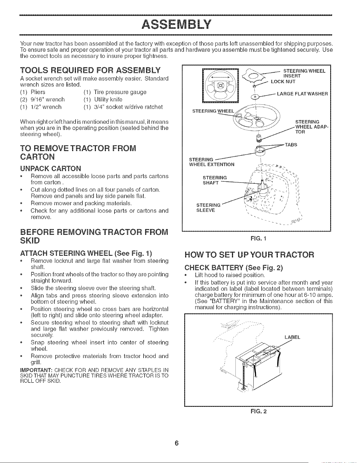
FIG, 1
ATTACH STEERING WHEEL (See Fig, 1)
• Remove Iocknut and large flat washer from steering
shaft,
Position front wheels of the tractor so they are pointing
straight forward,
o Slide the steering sleeve over the steering shaft,
o Align tabs and press steering sleeve extension into
bottom of steering wheel,
o Position steering wheel so cross bars are horizontal
(left to right) and slide onto steering wheel adapter,
o Secure steering wheel to steering shaft with Iocknut
and large flat washer previously removed, Tighten
securely,
Snap steering wheel insert into center of steering
wheel,
Remove protective materials from tractor hood and
griN,
IMPORTANT: CHECK FOR AND REMOVE ANY STAPLES iN
SKID THAT MAY PUNCTURETIRES WHERE TRACTOR iS TO
ROLL OFF SKID.
HOW TO SET UP YOUR TRACTOR
CHECK BATTERY (See Fig. 2)
Lift hood to raised position.
if this battery is put into service after month and year
indicated on label (label located between terminals)
charge battery for minimum of one hour at 6-10 amps.
(See "BATTERY" in the Maintenance section of this
manual for charging
FIG, 2
6
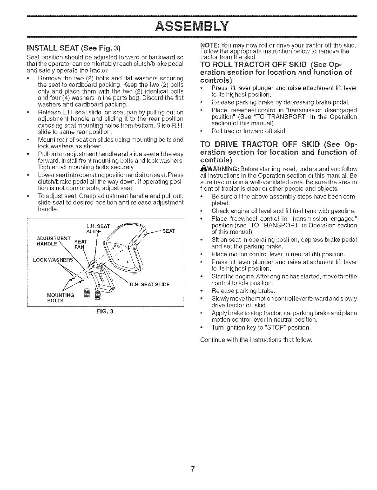
iNSTALL SEAT (See Fig. 3)
Seat positbn should be adjusted forward or backward so
that the operator can comfortaMy reach dutch/brake pedal
and safely operate the tractor,
o Remove the two (2) bolts and fiat washers securing
the seat to cardboard packing, Keep the two (2) bolts
only and place them with the two (2) identical bolts
and four (4) washers in the parts bag, Discard the fiat
washers and cardboard packing,
o Rebase L,H, seat slide on seat pan by pulling out on
adjustment handb and sliding it to the rear positbn
exposing seat mounting hobs from bottom, SHde R,H,
slide to same rear positbn,
* Mount rear of seat on slides using mounting bolts and
bck washers as shown,
* Pull out on adjustment handb and slide seat aHthe way
forward, Install front mounting bolts and lock washers,
Tighten all mounting bolts securely,
o Lower seat into operating position and sit on seat, Press
clutch/brake pedal all the way down, If operating posi-
tion is not comfortable, adjust seat,
* To adjust seat: Grasp adjustment handle and pull out,
slide seat to desired position and release adjustment
handle,
ADJUSTMENT
L.H. SEAT
SU[
SEAT
MOUNTmNG
BOLTS
FmG°3
TO ROLL TRACTOR OFF SKmD (See Op-
eration section for _ocation and function of
controJs}
o Press lift lever plunger and raise attachment lift lever
to its highest position,
o Release parking brake by depressing brake pedal,
o Place freewheel control in "transmission disengaged
position" (See "TO TRANSPORT" in the Operation
section of this manual),
* Roll tractor forward off skid,
TO DRIVE TRACTOR OFF SKID (See Op-
eration section for _ocation and function of
controls}
,_kWARNING: Before starting, read, understand and follow
all instructions in the Operation section of this manual, Be
sure tractor is in a welPventilated area, Be sure the area in
front of tractor is clear of other people and objects,
o Be sure all the above assembly steps have been com-
pbted,
* Check engine oil level and fill fuel tank with gasoline,
o Place freewheel control in "transmission engaged"
position (see "TO TRANSPORT" in Operation section
of this manual),
* Sit on seat in operating position, depress brake pedal
and set the parking brake,
* Place motion control lever in neutral (N) position,
* Press lift lever plunger and raise attachment lift lever
to its highest position,
* Start the engine,After engine has started, move throttb
* Release parking brake,
* Slowly move the motion control lever forward and slowly
drive tractor off skid,
o Apply brake to stop tractor, set parking brake and place
motion control lever in neutral position,
o Turn ignition key to "STOP" position,
Continue with the instructions that follow,
ASSEMBLY
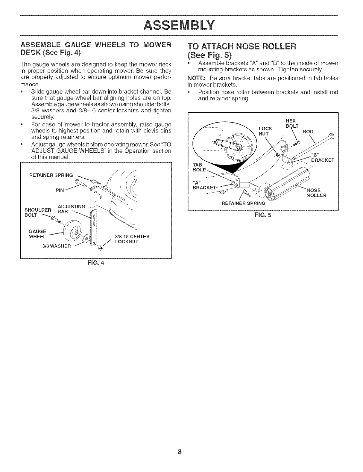
ASSEMBLE GAUGE WHEELS TO MOWER
DECK (See Fig. 4)
The gauge wheeb are designed to keep the mower deck
in proper position when operating mower, Be sure they
are properUy adjusted to ensure optimum mower perfor-
mance,
o SHde gauge wheeUbar down into bracket channeU, Be
sure that gauge wheeUbar aligning hobs are on top,
AssemMe gauge wheeb as shown using shouUderbouts,
3/8 washers and 3/8o16 center bcknuts and tighten
secureUy,
o For ease of mower to tractor assembUy, raise gauge
wheeUs to highest position and retain with cbvis pins
and spring retainers,
o Adjust gauge wheeUsbefore operating mower, See "TO
ADJUST GAUGE WHEELS" in the Operation section
of this manual
RETAINER SPRING
PIN
ADJUSTmNG
SHOULDER BAR
BOLT--.%
GAUGE
WHEEL
3!BWASNER
3/8=16 CENTER
LOCKNUT
TO ATTACH NOSE ROLLER
(See Fig. 5}
Assembb brackets "A" and "B" to the inside of mower
mounting brackets as shown, Tighten securely,
NOTE: Be sure bracket tabs are positioned in tab holes
in mower brackets,
Position nose roller between brackets and install rod
and retainer spring,
HEX
BOLT
LOCK
NUT ROD
BRACKET
RETAINER SPRING
FIG. 5
ROLLER
FmG.4
8
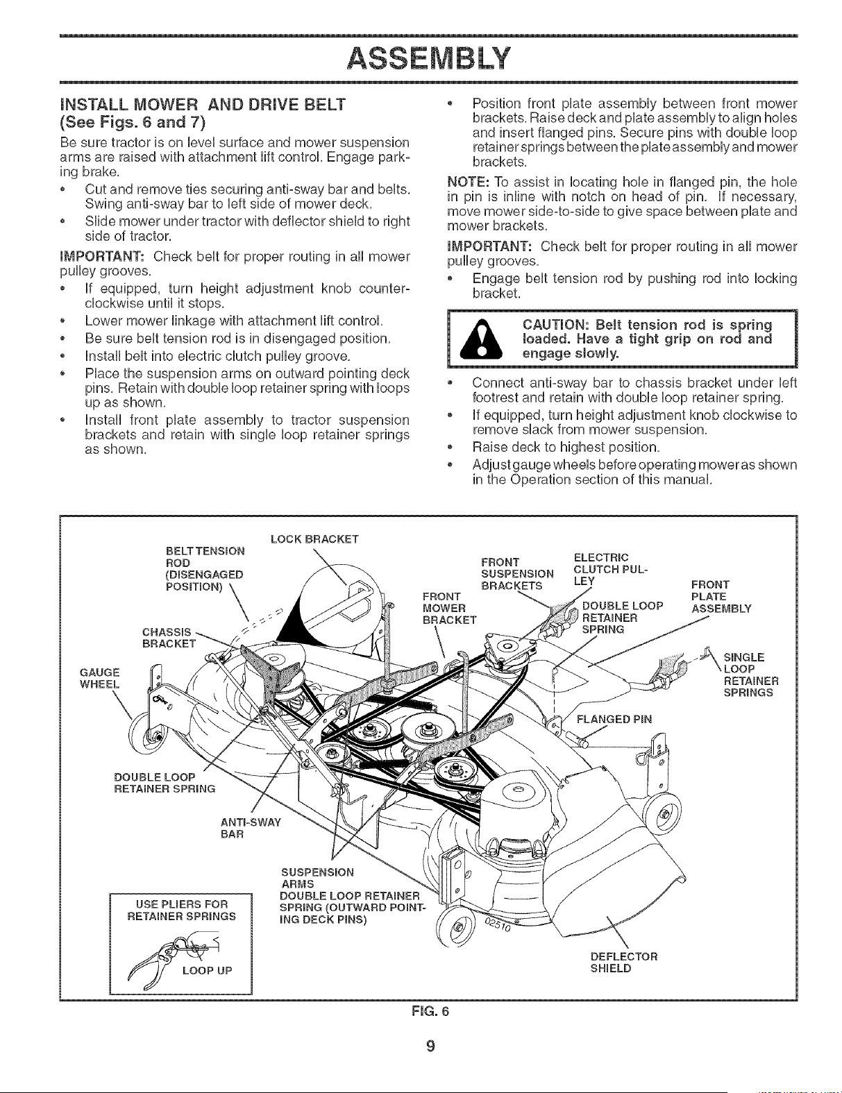
iNSTALL MOWER AND DRIVE BELT
(See Figs. 6 and 7)
Be sure tractor is on UeveUsurface and mower suspension
arms are raised with attachment Hftcontrol Engage park°
ing brake,
* Cut and remove ties securing anti-sway bar and beUts,
Swing anti-sway bar to Ueftside of mower deck,
* SHde mower under tractor with deflector shieUdto right
side of tractor,
IMPORTANT: Check beUtfor proper routing in aH mower
pulley grooves,
* Uf equipped, turn height adjustment knob counter-
clockwise until it stops,
o Lower mower Hnkage with attachment Hft control
o Be sure beUttension rod is in disengaged position,
o UnstaHbelt into electric clutch pulley groove,
o Place the suspension arms on outward pointing deck
pins, Retain with double loop retainer spring with loops
up as shown,
o Install front plate assembly to tractor suspension
brackets and retain with single loop retainer springs
as shown,
Position front plate assembly between front mower
brackets, Raise deck and plate assembly to align holes
and insert flanged pins, Secure pins with double loop
retainer springs between the plate assembly and mower
brackets,
NOTE: To assist in locating hole in flanged pin, the hole
in pin is inline with notch on head of pin, If necessary,
move mower side4o-side to give space between plate and
mower brackets,
IMPORTANT: Check belt for proper routing in all mower
pulley grooves,
o Engage belt tension rod by pushing rod into locking
bracket,
* Connect anti-sway bar to chassis bracket under left
footrest and retain with double loop retainer spring,
o if equipped, turn height adjustment knob clockwise to
remove slack from mower suspension,
o Raise deck to highest position,
o Adjust gauge wheels before operating mower as shown
in the Operation section of this manual,
GAUGE
WHEEL
\
LOCK BRACKET
BELT TENSION
ROD
(DBENGAGED
POSmON)
\
CHASSIS /_ "
FRONT
MOWER
BRACKET
FRONT ELECTRIC
SUSPENSION CLUTCH PULo
BRACKETS LEY
FLANGED PIN
FRONT
PLATE
ASSEMBLY
SINGLE
RETAINER
SPRINGS
DOUBLELOOP
RETAINER SPRING
ANTFSWAY
BAR
USE PUERS FOR
RETAINER SPRINGS
LOOPUP
SUSPENSION
ARMS
DOUBLE LOOP RETAINER
SPRING (OUTWARD POINT-
ING DECK PmNS)
DEFLECTOR
SHIELD
FIG. 6

CHECK TIRE PRESSURE
The tires on your tractor were ovednfiated at the factory
for shipping purposes. Correct tire pressure is important
for best cutting performance.
o Reduce tire pressure to PSU shown in "PRODUCT
SPECIFICATIONS" section of this manual
CHECK MOWER LEVELNESS
For best cutting resuUts,mower shouUdbe properUy UeveUed.
See "TO LEVEL MOWER HOUSUNG" in the Service and
Adjustments section of this manual
CHECK FOR PROPER POSITION OF ALL
BELTS
See the figures that are shown for repUacingmotion, mower
drive, and mower bUadedrive beUtsin the Service and Ad-
justments section of this manual Verify that the beUtsare
routed correctUy.
CHECK BRAKESYSTEM
After you Uearnhow to operate your tractor, check to see that
the brake is properUy adjusted. See "TO ADJUST BRAKE"
in the Service and Adjustments section of this manual.
,/CHECKLIST
BEFORE YOU OPERATE AND ENJOYYOUR NEW TRAC-
TOR, WE WISH TO ASSURE THAT YOU RECEIVE THE
BESTPERFORMANCE AND SATISFACTION FROM THIS
QUALITY PRODUCT.
PLEASE REVIEW THE FOLLOWING CHECKLIST:
v_ All assembly instructions have been completed.
v_ No remaining loose parts in carton.
v_ Battery is properly prepared and charged. (Minimum
1 hour at 6 amps).
v_ Seat is adjusted comfortably and tightened securely.
v_ All tires are properly inflated. (For shipping purposes,
the tires were overinfiated at the factory).
v" Be sure mower deck is properly leveled side-to-side/
front-to-rear for best cutting results. (Tires must be
properly inflated for leveling).
v" Check mower and drive belts. Be sure they are routed
properly around pulleys and inside all belt keepers.
v_ Check wiring. See that all connections are still secure
and wires are properly clamped.
v_ Before driving tractor, be sure freewheel control is in
drive position.
WHILE LEARNING HOW TO USE YOUR TRACTOR, PAY
EXTRA ATTENTION TO THE FOLLOWING IMPORTANT
ITEMS:
v" Engine oil is at proper level.
./ Fuel tank is filled with fresh, clean, regular unleaded
gasoline.
v_ Become familiar with all controls - their location and
function. Operate them before you start the engine.
v" Be sure brake system is in safe operating condition.
v" It is important to purge the transmission before oper-
ating your tractor for the first time. Follow proper start°
ing and transmission purging instructions (See "TO
START ENGINE" and "PURGE TRANSMISSION" in
the Operation section of this manual).
10
OPERATION
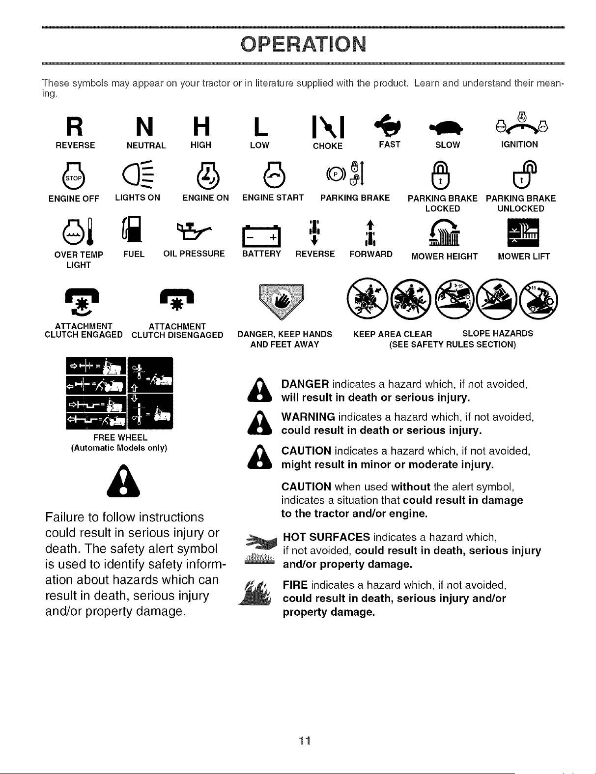
These symboUs may appear on your tractor or in Hterature supplied with the product, Learn and understand their mean-
ing,
R N
REVERSE NEUTRAL HIGH LOW CHOKE FAST SLOW
L IXI o,. o
IGNITION
G @ e
ENGINE OFF LIGHTS ON ENGINE ON ENGINE START PARKING BRAKE
OVER TEMP FUEL OIL PRESSURE BATTERY REVERSE FORWARD
LIGHT
PARKING BRAKE PARKING BRAKE
LOCKED UNLOCKED
MOWER HEIGHT MOWER LIFT
ATTACHMENT
CLUTCH ENGAGED
ATTACHMENT
CLUTCH DISENGAGED DANGER, KEEP HANDS
AND FEET AWAY
®@@@@
KEEP AREA CLEAR SLOPE HAZARDS
(SEE SAFETY RULES SECTION)
FREEWHEEL
(Automatic Models only)
&
Failure to follow instructions
could result in serious injury or
death. The safety alert symbol
is used to identify safety inform-
ation about hazards which can
result in death, serious injury
and/or property damage.
&
&
&
,_t_tlllllNtl,,
DANGER indicates a hazard which, if not avoided,
will result in death or serious injury.
WARNING indicates a hazard which, if not avoided,
could result in death or serious injury.
CAUTION indicates a hazard which, if not avoided,
might result in minor or moderate injury.
CAUTION when used without the alert symbol,
indicates a situation that could result in damage
to the tractor and/or engine.
HOT SURFACES indicates a hazard which,
if not avoided, could result in death, serious injury
and/or property damage.
FIRE indicates a hazard which, if not avoided,
could result in death, serious injury and/or
property damage.
11
OPERATION
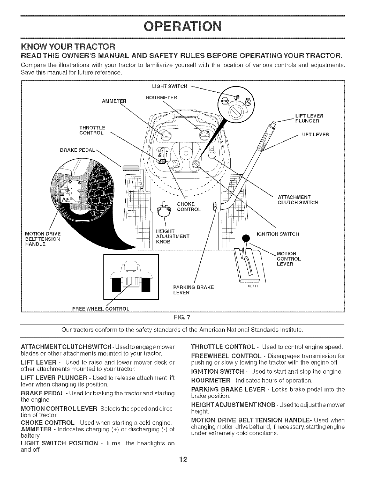
KNOW YOU R TRACTOR
READ'THIS OWNER'S MANUAL AND SAFETY RULES BEFORE OPERATmNG YOUR TRACTOR.
Compare the illustrations with your tractor to familiarize yourself with the location of various controls and adjustments,
Save this manual for future reference,
LIGHT SWmTCH
ROURMETER
AMMETER
THROTTLE
CONTROL
LiFT LEVER
PLUNGER
LIFT LEVER
BRAKE
MOTmON DRIVE
BELTTENSmON
HANDLE
CHOKE
CONTROL
HEmGHT
ADJUSTMENT
KNOB
PARKING BRAKE
LEVER
02711
ATTACHMENT
CLUTCH SWITCH
SWITCH
MOTION
CONTROL
LEVER
FREEWHEEL CONTROL
FiG. 7
Our tractors conform to the safety standards of the American National Standards Institute,
ATTACHMENT CLUTCH SWITCH - Used to engage mower
blades or other attachments mounted to your tractor,
LIFT LEVER = Used to raise and lower mower deck or
other attachments mounted to your tractor,
LIFT LEVER PLUNGER - Used to release attachment lift
lever when changing its position,
BRAKE PEDAL - Used for braking the tractor and starting
the engine,
MOTION CONTROL LEVER- Selects the speed and direc-
tion of tractor,
CHOKE CONTROL - Used when starting a cold engine,
AMMETER - Indocates charging (+) or discharging (-) of
battery,
LIGHT SWITCH POSITION - Turns the headlights on
and off,
THROTTLE CONTROL - Used to control engine speed,
FREEWHEEL CONTROL - Disengages transmission for
pushing or slowly towing the tractor with the engine off,
IGNITION SWITCH - Used to start and stop the engine,
HOURMETER - indicates hours of operation,
PARKING BRAKE LEVER - Locks brake pedal into the
brake position,
HEIGHT ADJUSTMENT KNOB - Used to adjust the mower
MOTION DRIVE BELT TENSION HANDLE- Used when
changing motion drive belt and, if necessary, starting engine
under extremely cold conditions,
12
OPERATION
HOW TO USE YOUR TRACTOR
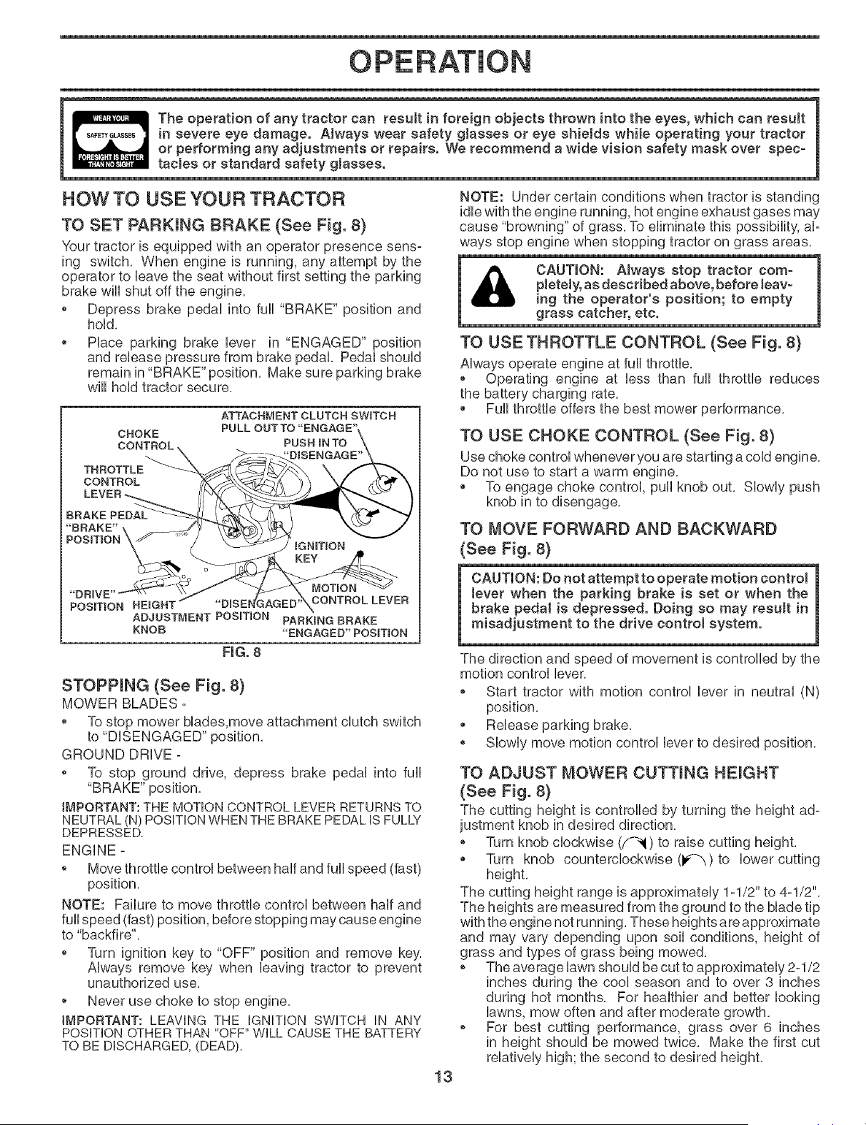
TO SET PARKING BRAKE (See Fig. 8)
Your tractor is equipped with an operator presence sens-
ing switch, When engine is running, any attempt by the
operator to leave the seat without first setting the parking
brake will shut off the engine,
• Depress brake pedal into full "BRAKE" position and
hold,
o Place parking brake lever in "ENGAGED" position
and release pressure from brake pedal, Pedal should
remain in "BRAKE" position, Make sure parking brake
wiii hold tractor secure,
CHOKE
CONTROL
THBOTTLE
CONTBOL
ATTACHMENT CLUTCH SWITCH
PULL OUT TO "ENGAGE'
PUSH IN TO
"DRIVE'
PosmoN HEIGHT
ADJUSTMENT POSmON
KNOB
CONTBOLLEVEB
PABKmNG BBAKE
"ENGAGED'POSITION
FmG.8
STOPPmNG (See Fig. 8)
MOWER BLADES -
To stop mower blades,move attachment clutch switch
to "DISENGAGED" position,
GROUND DRIVE -
To stop ground drive, depress brake pedal into full
"BRAKE" position,
IMPORTANT: THE MOTION CONTROL LEVER RETURNS TO
NEUTRAL (N) POSITION WHEN THEBRAKE PEDAL IS FULLY
DEPRESSED.
ENGINE -
o Move throttle control between half and full speed (fast)
position.
NOTE: Failure to move throttle control between half and
full speed (fast) position, before stopping may cause engine
to "backfire".
Turn ignition key to "OFF" position and remove key,
Always remove key when leaving tractor to prevent
unauthorized use,
o Never use choke to stop engine,
IMPORTANT: LEAVING THE iGNiTiON SWITCH iN ANY
POSiTiON OTHER THAN "OFF" WiLL CAUSE THE BATTERY
TO BE DISCHARGED, (DEAD).
13
NOTE: Under certain conditions when tractor is standing
idle with the engine running, hot engine exhaust gases may
cause "browning" of grass, To eliminate this possibility, al=
ways stop engine when stopping tractor on grass areas,
CAUTION: Always stop tractor com-
pletely, as described above, before leav-
ing the operator's position; to empty
grass catcher, etc.
TO USE THROTTLE CONTROL (See Fig. 8)
Always operate engine at full throttle,
o Operating engine at less than full throttle reduces
the battery charging rate,
Full throttle offers the best mower performance,
TO USE CHOKE CONTROL (See Fig. 8)
Use choke control whenever you are starting a cold engine,
Do not use to start a warm engine,
To engage choke control, pull knob out, Slowly push
knob in to disengage,
TO MOVE FORWARD AND BACKWARD
(See Fig. 8)
CAUTION: Do not attempt to operate motion control
tever when the parking brake is set or when the
brake pedaJ is depressed. Doing so may result in
misadjustment to the drive control system.
The direction and speed of movement is controlled by the
motion control lever,
o Start tractor with motion control lever in neutral (N)
position,
Release parking brake,
o Slowly move motion control lever to desired position,
TO ADJUST MOWER CUTTING HEIGHT
(See Fig, 8)
The cutting height is controlled by turning the height ad-
justment knob in desired direction,
o Turn knob clockwise (f_i) to raise cutting height,
Turn knob counterclockwise (_) to lower cutting
height.
The cutting height range is approximately 1=1/2" to 4-1/2",
The heights are measured from the ground to the blade tip
with the engine not running, These heights are approximate
and may vary depending upon soil conditions, height of
grass and types of grass being mowed,
o The average lawn should be cut to approximately 2=1/2
inches during the cool season and to over 3 inches
during hot months, For healthier and better looking
lawns, mow often and after moderate growth,
o For best cutting performance, grass over 6 inches
in height should be mowed twice, Make the first cut
relatively high; the second to desired height,
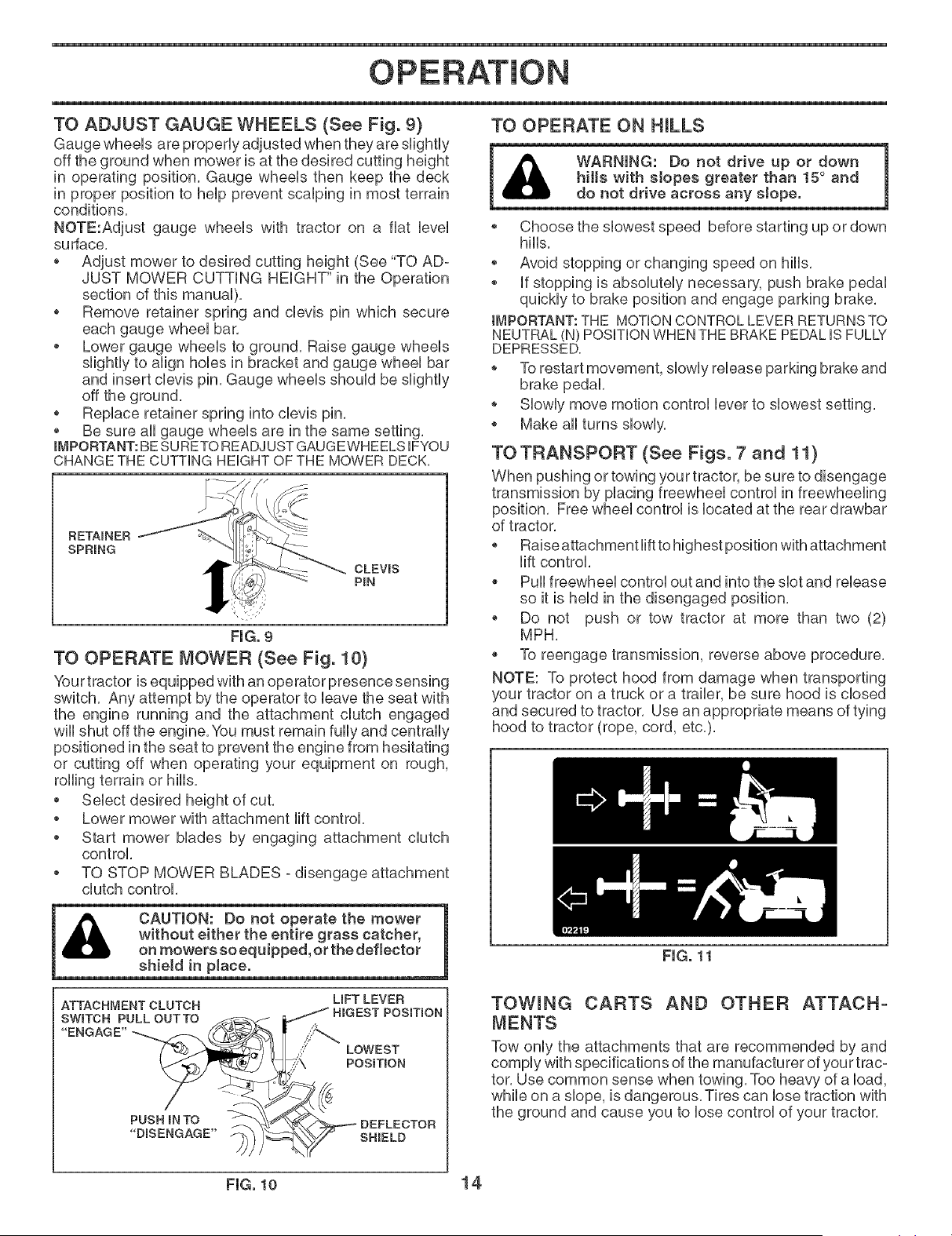
TO ADJUST GAUGE WHEELS (See Fig. 9)
Gauge wheeUs are properUyadjusted when they are sHghtUy
off the ground when mower is at the desired cutting height
in operating position, Gauge wheeb then keep the deck
in proper position to heUpprevent scaUping in most terrain
conditions,
NOTE:Adjust gauge wheeUs with tractor on a fiat bveU
su dace,
o Adjust mower to desired cutting height (See "TO AD-
JUST MOWER CUTTING HEIGHT" in the Operation
section of this manuaU),
o Remove retainer spring and cbvb pin which secure
each gauge wheeUbar,
o Lower gauge wheeb to ground, Raise gauge wheeUs
sHghtUyto align hobs in bracket and gauge wheeU bar
and insert cbvb pin, Gauge wheeUs shouUd be slightly
off the ground,
o Replace retainer spring into clevis pin,
* Be sure all gauge wheels are in the same setting,
iMPORTANT:BESURETO READJUSTGAUGEWHEELS IFYOU
CHANGE THE CUTTING HEIGHT OF THE MOWER DECK.
TO OPERATE ON HILLS
RETAINER
SPRING
CLEVmS
PIN
, '}.<"
FmG°9
TO OPERATE MOWER (See Fig. 10}
Your tractor is equipped with an operator presence sensing
switch, Any attempt by the operator to leave the seat with
the engine running and the attachment clutch engaged
will shut off the engine, You must remain fully and centrally
positioned in the seat to prevent the engine from hesitating
or cutting off when operating your equipment on rough,
rolling terrain or hills,
* Select desired height of cut,
o Lower mower with attachment lift control,
o Start mower blades by engaging attachment clutch
control,
o TO STOP MOWER BLADES - disengage attachment
clutch control,
CAUTION: Do not operate the mower
without either the entire grass catcher,
on mowers so equipped, or the deflector
shield in place.
ATTACHMENT CLUTCH
W'TO E ULLOUTTO
UFT LEVER
HIGEST POSmON
,_!//£_'_ LOWEST
• POSITION
s% CT°R
* Choose the slowest speed before starting up or down
hills,
* Avoid stopping or changing speed on hills,
* If stopping is absolutely necessary, push brake pedal
quickly to brake position and engage parking brake,
IMPORTANT: THE MOTION CONTROL LEVER RETURNSTO
NEUTRAL (N) POSITIONWHEN THE BRAKE PEDAL IS FULLY
DEPRESSED.
o To restart movement, slowly release parking brake and
brake pedal,
o Slowly move motion control lever to slowest setting,
o Make all turns slowly,
TO TRANSPORT (See Figs. 7 and 11)
When pushing or towing your tractor, be sure to disengage
transmission by placing freewheel control in freewheeling
position, Free wheel control is located at the rear drawbar
of tractor,
o Raise attachment lift to highest position with attachment
lift control,
* Pull freewheel control out and into the slot and release
so it is held in the disengaged position,
* Do not push or tow tractor at more than two (2)
MPH,
* To reengage transmission, reverse above procedure,
NOTE: To protect hood from damage when transporting
your tractor on a truck or a trailer, be sure hood is closed
and secured to tractor, Use an appropriate means of tying
hood to tractor (rope, cord, etc,),
FIG. 11
TOWING CARTS AND OTHER ATTACH°
MENTS
Tow only the attachments that are recommended by and
comply with specifications of the manufacturer of your trac-
tor, Use common sense when towing, Too heavy of a load,
while on a slope, is dangerous, Tires can lose traction with
the ground and cause you to lose control of your tractor,
FIG. 10 14
OPERATION
BEFORE STARTING THE ENGINE
CHECK ENGmNE OIL LEVEL
The engine in your tractor has been shipped, from the
factory, already tiffed with summer weight o&
* Check engine oil with tractor on bvel ground,
* Unthread and remove oil tiff cap/dipstbk; wipe oil off,
Reinsert the dipstick into the tube and rest oil tiff cap on
the tube, Do not thread the cap onto the tube, Remove
and read oil bvel, if necessary, add oil until "FULl"
mark on dipstick is reached, Do not overfifl,
* For cold weather operation you should change oil for
easier starting (See "OIL VISCOSITY CHART" in the
Maintenance section of this manual),
, To change engine oil, see the Maintenance section in
this manual,
ADD GASOLINE
* Fill fuel tank to bottom of filler neck, Do not overfill,
Use fresh, clean, regular unleaded gasoline with a
minimum of 87 octane, (Use of leaded gasoline will
increase carbon and lead oxide deposits and reduce
valve life), Do not mix oil with gasoline, Purchase fuel
in quantities that can be used within 30 days to assure
fuel freshness,
IMPORTANT: WHEN OPERATING iN TEMPERATURES
BELOW32°F(0°C), USE FRESH, CLEAN WINTER GRADE
GASOLINE TO HELP iNSURE GOOD COLD WEATHER
STARTING.
CAUTION: Atcohol bJended fuels (called
gasohoJ or using ethanol or methano0 can at=
tract moisture which Jeads to separation and
formation of acids during storage. Acidic gas
can damage the fue! system of an engine while
in storage. To avoid engine problems, the fuel
system should be emptied before storage of
30 days or tonger. Drain the gas tank, start
the engine and tet it run until the fueJ lines
and carburetor are empty. Use fresh fuet next
season. See Storage instructions for additionaJ
information. Never use engine or carburetor
cleaner products in the fuet tank or permanent
damage may occur.
TO START ENGINE (See Fig. 8)
When starting the engine for the first time or if the engine
has run out of fuel, it will take extra cranking time to move
fuel from the tank to the engine,
° Be sure freewheel control is in the transmission engaged
position,
* Sit on seat in operating position, depress brake pedal
and set parking brake,
* Move attachment clutch to "DISENGAGED" position,
* Move throttle control to fast position
* Pull choke control out for a cold engine start attempt,
For a warm engine start attempt the choke control may
not be needed,
NOTE: Before starting, read the warm and cold starting
procedures below,
o Insert key into ignition and turn key clockwise to
"START" position and release key as soon as engine
starts, Do not run starter continuously for more than
fifteen seconds per minute, If the engine does not start
after several attempts, push choke control in, wait a
few minutes and try again, If engine still does not start,
pull the choke control out and retry,
WARM WEATHER STARTING (50° F and above)
* When engine starts, slowly push choke control in until
the engine begins to run smoothly, If the engine starts
to run roughly, pull the choke control out slightly for a
few seconds and then continue to push the control in
slowly,
* The attachments and ground drive can now be used, if
the engine does not accept the load, restart the engine
and allow it to warm up for one minute using the choke
as described above,
COLD WEATHER STARTING (50 ° F and below)
, When engine starts, slowly push choke control in until
the engine begins to run smoothly, Continue to push
the choke control in small steps allowing the engine to
accept small changes in speed and load, until the choke
control is fully in, if the engine starts to run roughly, puff
the choke control out slightly for a few seconds and
then continue to push the control in slowly, This may
require an engine warm-up period from several seconds
to several minutes, depending on the temperature,
NOTE: in extreme cold conditions, if engine will not start, you
may need to disengage the motion drive belt as follows:
* Be sure parking brake is engaged,
, Remove retainer spring from the drive belt tension
handle to relieve belt tension,
* Start engine and allow it to warm up for three (3) min-
utes,
* Shut-off engine and engage parking brake,
* Engage drive belt tension handle and replace the
retainer spring,
AUTOMATIC TRANSMiSSiON WARM UP
o Before driving the unit in cold weather, the transmission
should be warmed up as follows:
* Be sure the tractor is on level ground,
, Place the motion control lever in neutral,
* Release the parking brake and let the brake
slowly return to operating position,
, Allow one minute for transmission to warm up,
This can be done during the engine warm up
period,
* The attachments can be used during the engine warm-
up period after the transmission has been warmed
up and may require the choke control be puffed out
slightly,
NOTE: if at a high altitude (above 3000 feet) or in cold
temperatures (below 32 F) the carburetor fuel mixture may
need to be adjusted for best engine performance, See "TO
ADJUST CARBURETOR" in the Service and Adjustments
section of this manual,
15
PURGETRANSMISSION
To ensure proper operation and performance, it is recom-
mended that the transmission be purged before operating
tractor for the first time, This procedure wiii remove any
trapped air inside the transmission which may have de-
veloped during shipping of your tractor,
IMPORTANT: SHOULD YOUR TRANSMiSSiON REQUIRE
REMC)VALFOR SERVICE OR REPLACEMENT, iT SHOULD
BE PURGEDAFTER REINSTALLATIONBEFORE OPERATING
THE TRACTOR.
* Place tractor safely on level su dace with engine off and
parking brake set,
, Disengage transmission by placing freewheel control
in freewheeling position (See"TO TRANSPORT" in this
section of manual),
* Sitting in the tractor seat, start engine, After the en-
gine is running, move throttle control to slow position,
Disengage parking brake
, Move motion control lever to full forward position and
hold for five (5) seconds, Move lever to fuji reverse
position and hold for five (5) seconds, Repeat this
procedure three (3) times,
NOTE: During this procedure there will be no movement
of drive wheels, The air is being removed from hydraulic
drive system,
* Move motion control lever to neutral (N) position, Shut-
off engine and set parking brake,
* Engage transmission by placing freewheel control in
driving position (See "TO TRANSPORT" in this section
of manual),
* Sitting in the tractor seat, start engine, After the engine
is running, move throttle control to half (1/2) speed,
Disengage parking brake,
* Slowly move motion control lever forward, after the
tractor moves approximately five (5) feet, slowly move
motion control lever to reverse position, After the trac-
tor moves approximately five (5) feet return the too°
tion control lever to the neutral (N) position, Repeat
this procedure with the motion control lever three (3)
times,
* Your transmission is now purged and now ready for
normal operation,
MOWING TiPS
° Tire chains cannot be used when the mower housing
is attached to tractor,
* Mower should be properly leveled for best mowing
performance, See"TO LEVEL MOWER HOUSING" in
the Service and Adjustments section of this manual,
, The left hand side of mower should be used for trim-
ming,
, Drive so that clippings are discharged onto the area
that has been cut, Have the cut area to the right of
the tractor, This wiii result in a more even distribution
of clippings and more uniform cutting,
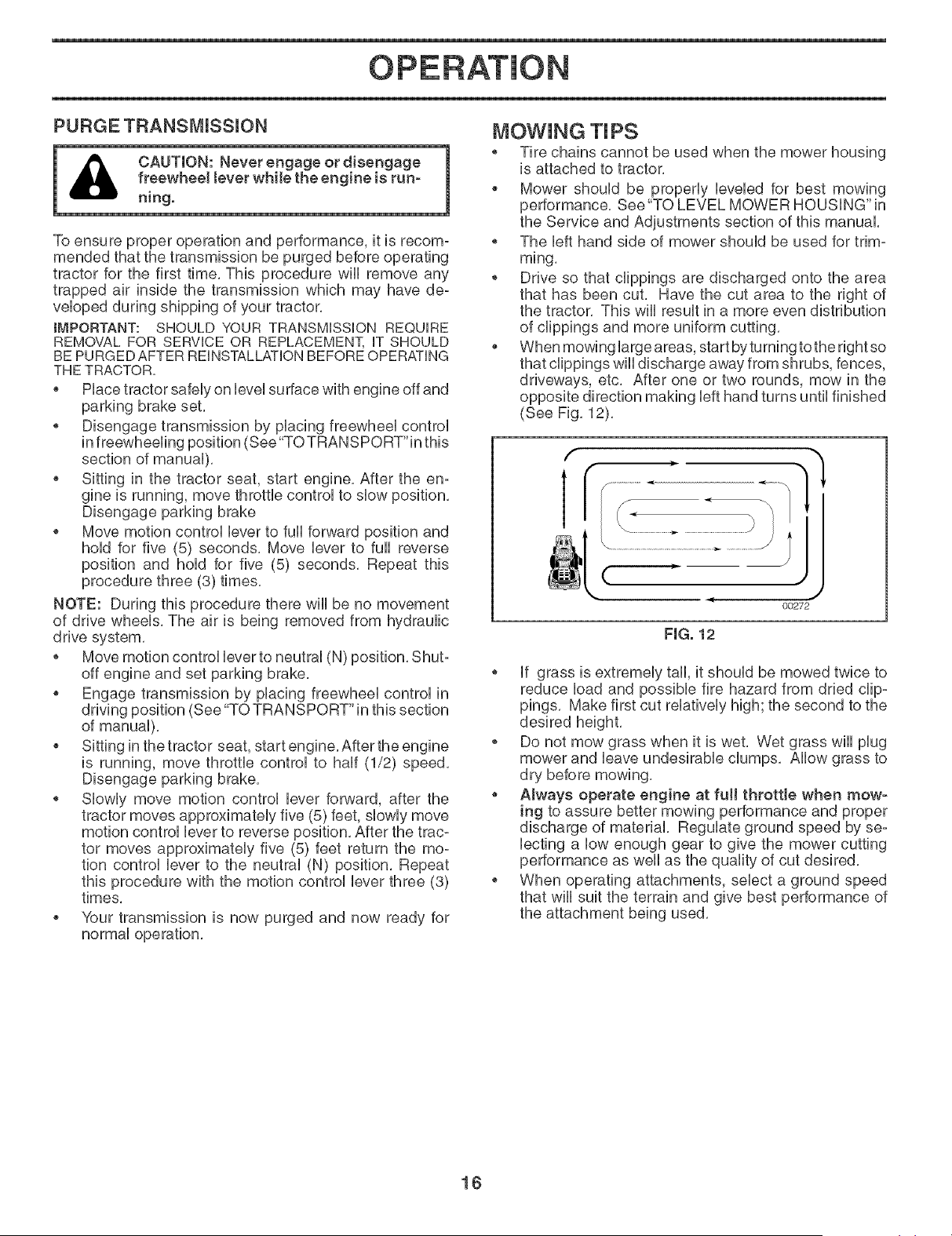
* When mowing large areas, start by turning tothe right so
that clippings will discharge away from shrubs, fences,
driveways, etc, After one or two rounds, mow in the
opposite direction making left hand turns until finished
(See Fig, 12),
f
l
(
00272
FIG. 12
* if grass is extremely tall, it should be mowed twice to
reduce load and possible fire hazard from dried clip-
pings, Make first cut relatively high; the second to the
desired height,
* Do not mow grass when it is wet, Wet grass will plug
mower and leave undesirable clumps, Allow grass to
dry before mowing,
* Always operate engine at fuji throttle when mow-
ing to assure better mowing performance and proper
discharge of material, Regulate ground speed by se°
lecting a low enough gear to give the mower cutting
performance as well as the quality of cut desired,
, When operating attachments, select a ground speed
that will suit the terrain and give best performance of
the attachment being used,
16
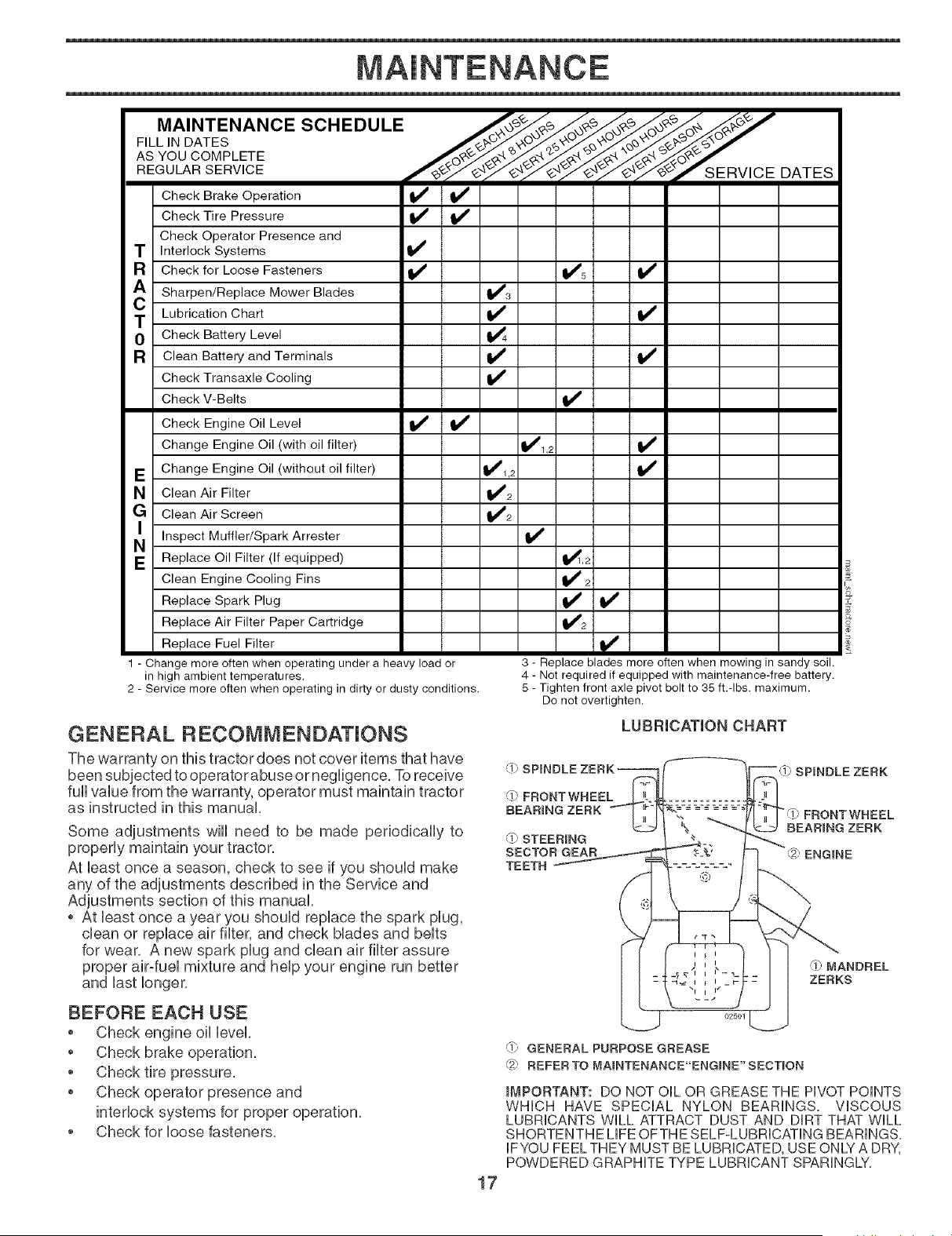
MAINTENANCE
F,LL,.OATES
ASYouCOMPLETE .......
REGULARSERVICE /_y_"_r_/'_'jl_ SERVICE DATES
Check Brake Operation _1_
Check Tire Pressure
Check Operator Presence and
T Interlock Systems li_
R Check for Loose Fasteners _ _5
A Sharpen/Replace Mower Blades 1_3
C Lubrication Chart _
0 Check Battery Level
R Clean Battery and Terminals I_
Check Transaxle Cooling I1_
Check V-Belts
Check Engine Oil Level li_ ll_
Change Engine Oil (with oil filter) _1_1,2 if
E Change Engine Oil (without oil filter) _1,2
N Clean Air Filter 1_2
G Clean Air Screen t#/2
NI Inspect Muffler/Spark
Arrester
E Replace Oil Filter (If equipped) I,_,2
Clean Engine Cooling Fins If 2
Replace Spark Plug II_ I1_
Replace Air Filter Paper Cartridge
V'2
Replace Fuel Filter
1 - Change more often when operating under a heavy load or
in high ambient temperatures.
2 - Service more often when operating in dirty or dusty conditions.
3 - Replace blades more often when mowing in sandy soil.
4 - Not required if equipped with maintenance-free battery.
5 - Tighten front axle pivot bolt to 35 ft.-Ibs, maximum.
Do not overtighten.
GENERAL RECOMMENDATIONS
The warranty on this tractor does not cover items that have
been subjected to operator abuse or negligence, To receive
fun vaUuefrom the warranty, operator must maintain tractor
as instructed in this manual
Some adjustments wHUneed to be made periodically to
propedy maintain your tractor,
At Ueastonce a season, check to see if you shouUd make
any of the adjustments described in the Service and
Adjustments section of this manual
o At Ueastonce a year you shouUdrepUacethe spark pUug,
dean or repUaceair fluter, and check Mades and beUts
for wear, A new spark pUugand dean air fluter assure
proper air-fueU mixture and help your engine run better
and last longer,
,11_,FRONTWNEEL
BEARING ZERK
,1i_,STEERmNG
SECTOR GEAR
TEETH
LUBRICATION CHART
SPINDLE ZERK
FRONTWHEEL
BEARING ZERK
ENGINE
'_'MANDREL
ZERKS
BEFORE EACH USE
Check engine oil level,
Check brake operation,
Check tire pressure,
Check operator presence and
interlock systems for proper operation,
Check for loose fasteners,
17
(0 GENERAL PURPOSE GREASE
'_#_ REFER TO MAINTENANCE"ENGINE"SECTmON
IMPORTANT: DO NOT OIL OR GREASE THE PIVOT POINTS
WHICH HAVE SPECIAL NYLON BEARING& VISCOUS
LUBRICANTS WILL ATTRACT DUST AND DIRT THAT WILL
SHORTENTHE LIFE OFTHE SELF-LUBRICATING BEARINGS.
IF YOU FEEL THEY MUST BE LUBRICATED, USE ONLY A DRY,
POWDERED GRAPHITE TYPE LUBRICANT SPARINGLY.

AUwaysobserve safety ruUeswhen performing any main-
tenance.
BRAKE OPERATmON
Uftractor requires more than six (6) feet stopping distance
at high speed in highest gear, then brake must be adjusted.
(See "TO ADJUST BRAKE" in the Service and Adjustments
TmRES
° Maintain proper air pressure
SPECIFICATIONS" section of this manuaU).
Keep tires free of gasoline, oH, or insect control chemi-
caUswhich can harm rubber.
* Avoid stumps, stones, deep ruts, sharp objects and
other hazards that may cause tire damage.
NOTE: To seaUtire punctures and prevent fiat tires due to
sUowUeaks,tire seaUant may be purchased from your UocaU
parts deaUer. Tire seaUant aUso prevents tire dry rot and
corrosion,
OPERATOR PRESENCE SYSTEM
Be su re operator presence and interUocksystems are work-
ing properly, Ufyou r tractor does not function as described,
repair the proNem immediately,
The engine should not start unless the brake pedal is
fully depressed and attachement clutch control is in
the disengaged position.
* When the engine is running, anyattempt bythe operator
to leave the seat without first setting the parking brake
should shut off the engine.
When the engine is running and the attachment clutch
is engaged, any attempt by the operator to leave the
seat should shut off the engine.
* The attachment clutch should never operate unless
the operator is in the seat..
BLADE CARE
For best results mower blades must be kept sharp, Replace
bent or damaged blades,
BLADE REMOVAL (See Fig. 13)
* Raise mower to highest position to allow access to
blades.
NOTE: Protect your hands with gloves and/or wrap blade
with heavy cloth.
Remove blade bolt by turning counterclockwise.
* Install new or resharpened blade with stamped "THIS
SIDE UP" facing deck and mandrel assembly.
IMPORTANT: TO ENSURE PROPER ASSEMBLY, CENTER
HOLE IN BLADE MUST ALIGN WITH STAR ON MANDREL
ASSEMBLY.
* Install and tighten blade bolt securely (45-55 Ft. Lbs.
torque).
IMPORTANT: SPECIAL BLADE BOLT HEAT TREATED.
BLADE CENTER
HOLE
MANDREL
ASSEMBLY
STAR
FIG. 13
TO SHARPEN BLADE (See Fig. 14)
NOTE: We do not recommend sharpening blade - but if
you do, be sure the blade is balanced,
Care should be taken to keep the blade balanced, An un-
balanced blade will cause excessive vibration and eventual
damage to mower and engine.
, The blade can be sharpened with a file or on a grind-
ing wheel. Do not attempt to sharpen while on the
mower.
To check blade balance, you will need a 5/8" diameter
steel bolt, pin, or a cone balancer. (When using a
cone balancer, follow the instructions supplied with
balancer.)
NOTE: Do not use a nail for balancing blade. The lobes of
the center hole may appear to be centered, but are not.
Slide blade on to an unth readed portion of the steel bolt
or pin and hold the bolt or pin parallel with the ground.
if blade is balanced, it should remain in a horizontal
position, if either end of the blade moves downward,
sharpen the heavy end until the blade is balanced.
CENTER HOLE /
/
5/8" BOLT
OR PmN
BLADE
FIG. 14
BATTERY
Your tractor has a battery charging system which is sufficient
for normal use, However, periodic charging of the battery
with an automotive charger will extend its life,
, Keep battery and terminals clean,
, Keep battery bolts tight,
, Keep small vent holes open,
, Recharge at 6=10 amperes for 1 hour,
NOTE: The original equipment battery on your tractor is
maintenance free, Do not attempt to open or remove caps
or covers, Adding or checking level of electrolyte is not
necessary.
18
MAINTENANCE
TO CLEAN BATTERY AND TERMINALS
Corrosion and dirt on the battery and terminals can cause
the battery to "leak" power,
Remove terminal guard,
o Disconnect BLACK battery cable first then RED bat-
tery cable and remove battery from tractor,
Rinse the battery with plain water and dry,
Clean terminals and battery cable ends with wire brush
until bright,
o Coat terminals with grease or petroleum jelly,
o Reinstall battery (See "REPLACING BATTERY" in
the SERVICE AND ADJUSTMENTS section of this
manual),
V-BELTS
Check V-belts for deterioration and wear after 100 hours
of operation and replace if necessary, The belts are not
adjustable, Replace belts if they begin to slip from wear,
TRANSAXLE COOUNG
The transmission fan and cooling fins should be kept clean
to assure proper cooling,
Do not attempt to clean fan or transmission while engine
is running or while the transmission is hot, To prevent pos-
sible damage to seals, do not use high pressure water or
steam to clean transaxle,
inspect cooling fan to be sure fan blades are intact and
clean,
inspect cooling fins for dirt, grass clippings and other
materials, To prevent damage to seals, do not use
compressed air or high pressure sprayer to clean coop
ing fins,
TRANSAXLE PUMP FLUmB
The transaxle was sealed at the factory and fluid mainte-
nance is not required for the life of the transaxle, Should
the transaxle ever leak or require servicing, contact your
nearest authorized service center/department,
ENGINE
LUBRICATmON
Only use high quality detergent oil rated with API service
classification SG-SL, Select the oil's SAE viscosity grade
according to your expected operating temperature
SAE VISCOSITY GRADES
W
F -20 0 30 32 40 60 80 100
_2_0 _ _ 1_0 _ _
C -30 -10 0 20 30 40
TEMPERATURE RANGE ANTICIPATED BEFORE NEXT OIL CHANGE
oil visc chart4
FIG. 15
Change the oil after every 50 hours of operation or at bast
once a year if the tractor is not used for 50 hours in one
year,
Check the crankcase oil level before starting the engine
and after each eight (8) hours of operation,
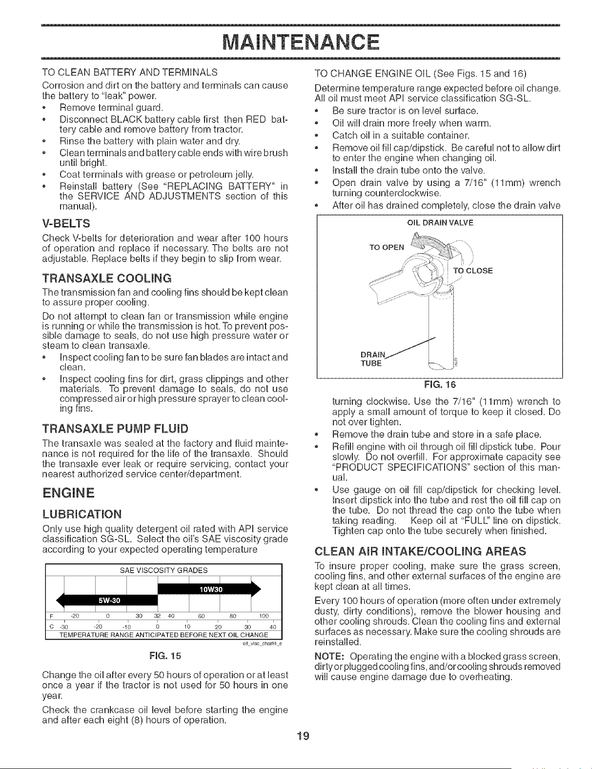
TO CHANGE ENGINE OiL (See Figs, 15 and 16)
Determine temperature range expected before oil change,
All oil must meet API service classification SG-SL,
Be sure tractor is on level surface,
Oil will drain more freely when warm,
Catch oil in a suitable container,
Remove oil fiii cap/dipstick, Be careful not to allow dirt
to enter the engine when changing oil,
Install the drain tube onto the valve,
Open drain valve by using a 7/16" (11mm) wrench
turning counterclockwise,
o After oil has drained completely, close the drain valve
OIL BRAIN VALVE
TO OPEN
\
\
DRAIN
TUBE
FIG. 16
turning clockwise, Use the 7/16" (11mm) wrench to
apply a small amount of torque to keep it closed, Do
not over tighten,
Remove the drain tube and store in a safe place,
Refill engine with oil through oil fill dipstick tube, Pour
slowly, Do not overfill, For approximate capacity see
"PRODUCT SPECiFiCATiONS" section of this man-
uak
Use gauge on oil fill cap/dipstick for checking level,
insert dipstick into the tube and rest the oil fill cap on
the tube, Do not thread the cap onto the tube when
taking reading, Keep oil at "FULE' line on dipstick,
Tighten cap onto the tube securely when finished,
CLEAN AIR mNTAKE/COOUNG AREAS
To insure proper cooling, make sure the grass screen,
cooling fins, and other external surfaces of the engine are
kept clean at all times,
Every 100 hours of operation (more often under extremely
dusty, dirty conditions), remove the blower housing and
other cooling shrouds, Clean the cooling fins and external
surfaces as necessary, Make sure the cooling shrouds are
reinstalled,
NOTE: Operating the engine with a blocked grass screen,
dirtyor plugged cooling fins, and/or cooling shrouds removed
will cause engine damage due to overheating,
19
MAINTENANCE
CLEAN AIR SCREEN
Air screen must be kept free of dirt and chaff to prevent
engine damage from overheating, Cban with a wire brush
or compressed air to remove dirt and stubborn dried gum
fibers, See engine manual,
AmR FILTER
Your engine wiii not run properly using a dirty air filter,
Service air cleaner more often under dusty conditions, See
engine manual,
ENGmNE OIL FILTER
Replace the engine oil filter every season or every other oil
change if the tractor is used more than 100 hours in one
year, See engine manual,
MUFFLER
inspect and replace corroded muffler and spark attester
(if equipped) as it could create a fire hazard and/or dam-
age,
SPARK PLUGS
Replace spark plugs at the beginning of each mowing
season or after every 100 hours of operation, whichever
occurs first, Spark plug type and gap setting are shown in
"PRODUCT SPECiFiCATiONS" section of this manual,
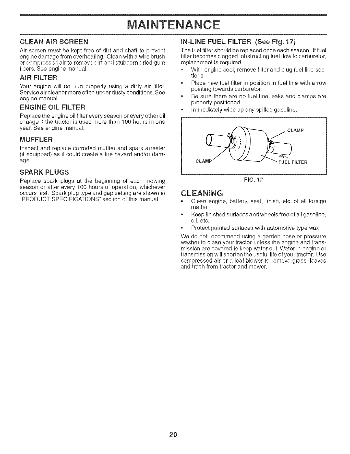
mN-UNE FUEL FILTER (See Fig. 17)
The fuel filter should be replaced once each season, if fuel
filter becomes clogged, obstructing fuel flow to carburetor,
replacement is required,
With engine cool, remove filter and plug fuel line sec-
tions,
Place new fuel filter in position in fuel line with arrow
pointing towards carburetor,
Be sure there are no fuel line leaks and clamps are
properly positioned,
o Immediately wipe up any spilled gasoline,
FIG. 17
Clean engine, battery, seat, finish, etc, of all foreign
matter,
Keep finished surfaces and wheels free of all gasoline,
oil, etc,
• Protect painted surfaces with automotive type wax,
We do not recommend using a garden hose or pressure
washer to clean your tractor unless the engine and trans-
mission are covered to keep water out, Water in engine or
transmission will shorten the useful life of your tractor, Use
compressed air or a leaf blower to remove grass, leaves
and trash from tractor and mower,
2O
SERVICE AND ADJUSTMENTS
WARNING: TO AVOID SERIOUS iNJURY, BEFORE PERFORMING ANY SERVICE OR ADJUST-
MENTS:
o Depress brake pedal fully and set parking brake.
® Place attachment clutch in "DISENGAGED" position.
, Turn ignition key to"STOP" and remove key.
, Make sure the blades and aH moving parts have completely stopped.
® Disconnect spark plug wire from spark plug and place wire where it cannot come in contact
with plug.
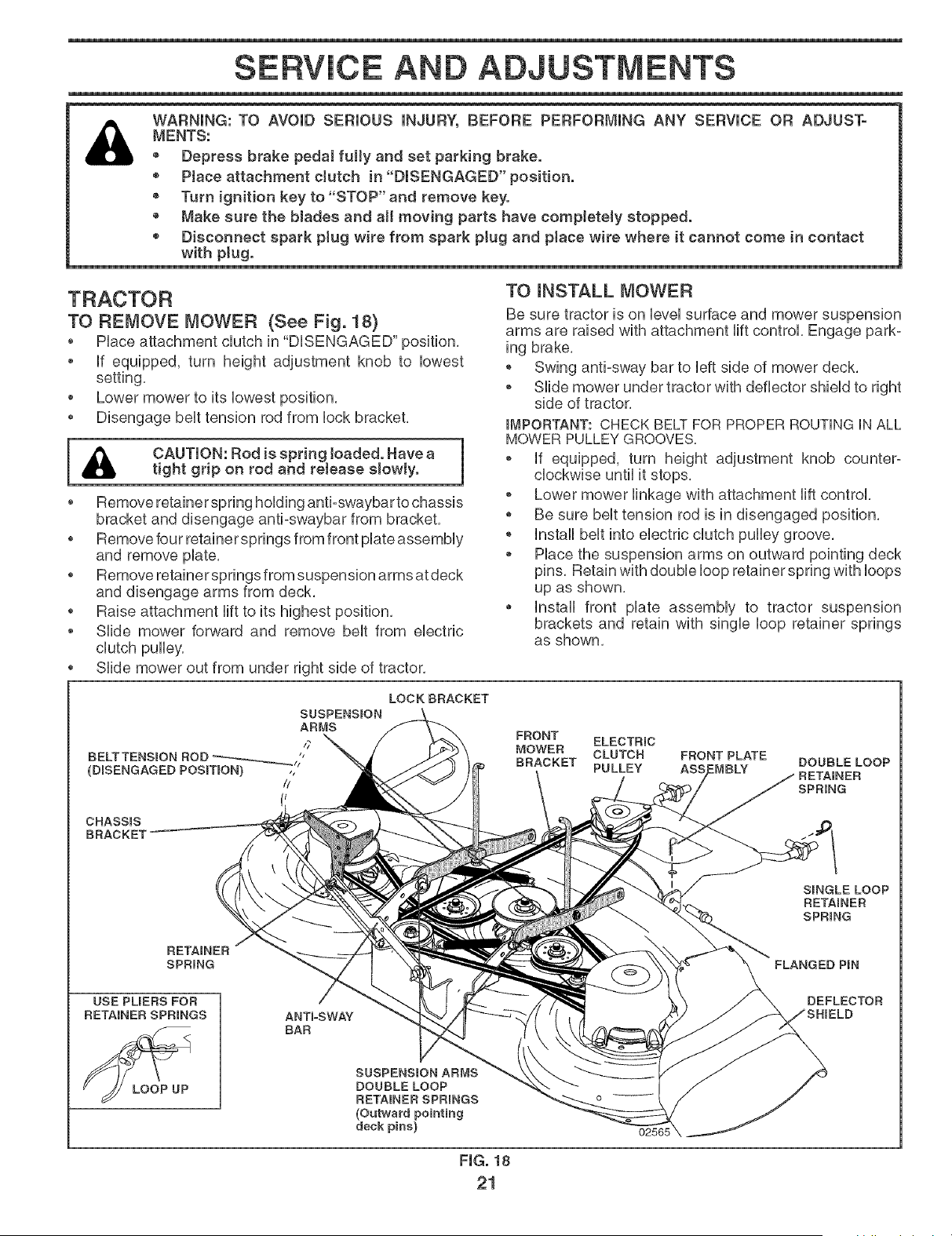
TO REMOVE MOWER (See Fig. 18)
[&
PUaceattachment dutch in "DUSENGAGED" position,
If equipped, turn height adjustment knob to lowest
setting,
Lower mower to its lowest position,
Disengage belt tension rod from lock bracket,
CAUTION: Rod is spring loaded. Have a 1
tight grip on rod and retease slowly.
1
Remove retainer spring holding anti-swaybar to chassis
bracket and disengage anti-swaybar from bracket,
o Remove four retainer springs from front plate assembly
and remove plate,
o Remove retainer springs from suspension arms at deck
and disengage arms from deck,
o Raise attachment lift to its highest position,
Slide mower forward and remove belt from electric
clutch pulley,
o Slide mower out from under right side of tractor,
TO mNSTALL MOWER
Be sure tractor is on level surface and mower suspension
arms are raised with attachment lift control, Engage park°
[ng brake,
o Swing anti-sway bar to left side of mower deck,
o Slide mower under tractor with deflector shield to right
side of tractor,
_MPORTANT: CHECK BELT FOR PROPER ROUTING IN ALL
MOWER PULLEY GROOVES=
o If equipped, turn height adjustment knob counter°
clockwise until it stops,
o Lower mower linkage with attachment lift control,
o Be sure belt tension rod is in disengaged position,
o Install belt into electric clutch pulley groove,
o Place the suspension arms on outward pointing deck
pins, Retain with double loop retainer spring with loops
up as shown,
Install front plate assembly to tractor suspension
brackets and retain with single loop retainer springs
as shown,
SUSPENSION
ARMS
/7
BELTTENSION ROD "_._//"
(DISENGAGED POSITION) ,,
//
LOCKBRACKET
FRONT ELECTRIC
MOWER CLUTCH FRONT PLATE
BRACKET PULLEY --MBLY
BOUBLELOOP
SPRING
CHASSIS
BRACKET
SINGLE LOOP
RETAINER
SPRING
SPRING
USE PUERS FOR
RETAINER SPRINGS
LOOP UP
ANTFSWAY
BAR
SUSPENSION ARMS
DOUBLE LOOP
RETAINER SPRINGS
(Outward pointing
deck pins)
o
FIG. 18
21
FLANGED PmN
DEFLECTOR
SERVICE AND ADJUSTMENTS
Position front plate assembly between front mower
brackets, Raise deck and plate assembly to align hobs
and insert flanged pins, Secure pins with doubb loop
retainer springs between the plate assembly and mower
brackets,
NOTE: To assist in locating hob in flanged pin, the hob in
pin is inline with notch on head of pin, if necessary, move
mower side-to-side to give space between plate and mower
brackets,
_MPORTANT: CHECK BELT FOR PROPER ROUTING iN ALL
MOWER PULLEY GROOVES.
* Engage belt tension rod by pushing rod into locking
bracket,
,_ CAUTION: Belt tension rod is spring
I _ toaded. Have a tight grip on rod and 1
en a e slowty.
* Connect anti-sway bar to chassis bracket under left
footrest and retain with double loop retainer spring,
* if equipped, turn height adjustment knob clockwise to
remove slack from mower suspension,
* Raise deck to highest position,
TO LEVEL MOWER HOUSING
Adjust the mower while tractor is parked on level ground
or driveway, Make sure tires are properly inflated (See
"PRODUCT SPECIFICATIONS" section of this manual), if
tires are over or underinfiated, you will not properly adjust
your mower,
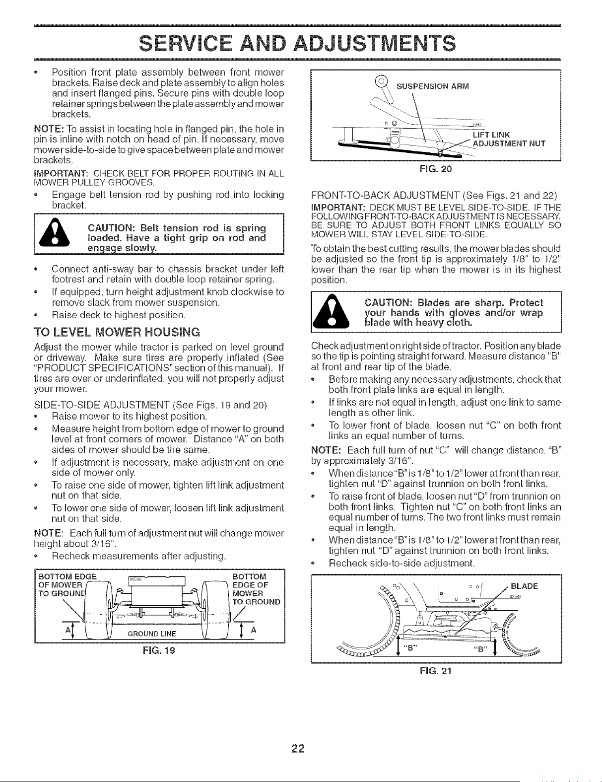
SIDE-TO-SIDE ADJUSTMENT (See Figs, 19 and 20)
* Raise mower to its highest position,
* Measure height from bottom edge of mower to ground
level at front corners of mower, Distance "A" on both
sides of mower should be the same,
* if adjustment is necessary, make adjustment on one
side of mower only,
* To raise one side of mower, tighten lift link adjustment
nut on that side,
* To lower one side of mower, loosen lift link adjustment
nut on that side,
NOTE: Each fuji turn of adjustment nut wiii change mower
height about 3/16",
* Recheck measurements after adjusting,
BOTTOM EDGE _ -1 BOTTOM
OF MOWER _ ! / _ EDGE OF
TOGBG0. itff--I imit IMOWEB
oooooo
s
FmG.19
SUSPENSION ARM
LIF'T UNK
FIG, 20
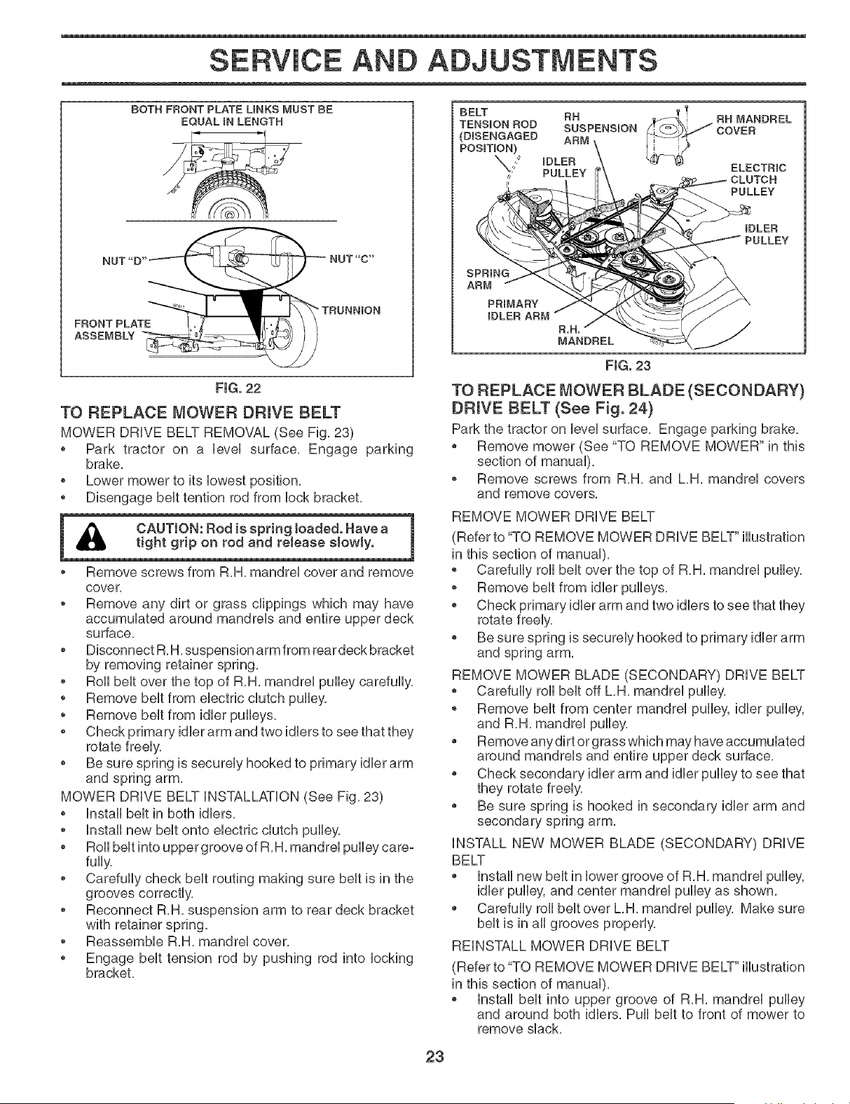
FRONT-TO-BACK ADJUSTMENT (See Figs, 21 and 22)
_MPORTANT: DECK MUST BE LEVEL SIDE-TO-SIDE. iF THE
FOLLOWING FRONT-TO-BACK ADJUSTMENT iS NECESSARY,
BE SURE TO ADJUST BOTH FRONT LINKS EQUALLY SO
MOWER WiLL STAY LEVEL SIDE-TO-SIDE.
To obtain the best cutting results, the mower blades should
be adjusted so the front tip is approximately 1/8" to 1/2"
lower than the rear tip when the mower is in its highest
position,
CAUTION: BJades are sharp. Protect
your hands with gloves and/or wrap
blade with heavy etoth.
Check adjustment on right side of tractor, Position any blade
so the tip is pointing straight forward, Measure distance "B"
at front and rear tip of the blade,
* Before making any necessary adjustments, check that
both front plate links are equal in length,
* if links are not equal in length, adjust one link to same
, To lower front of blade, loosen nut "C" on both front
links an equal number of turns,
NOTE: Each full turn of nut "C" will change distance, "B"
by approximately 3/16",
, When distance"B"is 1/8" to 1/2" lower at front than rear,
tighten nut "D" against trunnion on both front links,
, To raise front of blade, loosen nut"D" from trunnion on
both front links, Tighten nut "C" on both front links an
equal number of turns, The two front links must remain
equal in length,
* When distance"B"is 1/8" to 1/2" lower at front than rear,
tighten nut "D" against trunnion on both front links,
, Recheck side-to-side adjustment,
FmG.21
22
SERVICE AND ADJUSTMENTS
BOTH FRONT PLATE LINKS MUST BE
EQUAL iN LENGTH
NUT"D" NUT"C"
FRONT PLA!E I.o_ ,_ _
ASSEMBLY
FHG.22
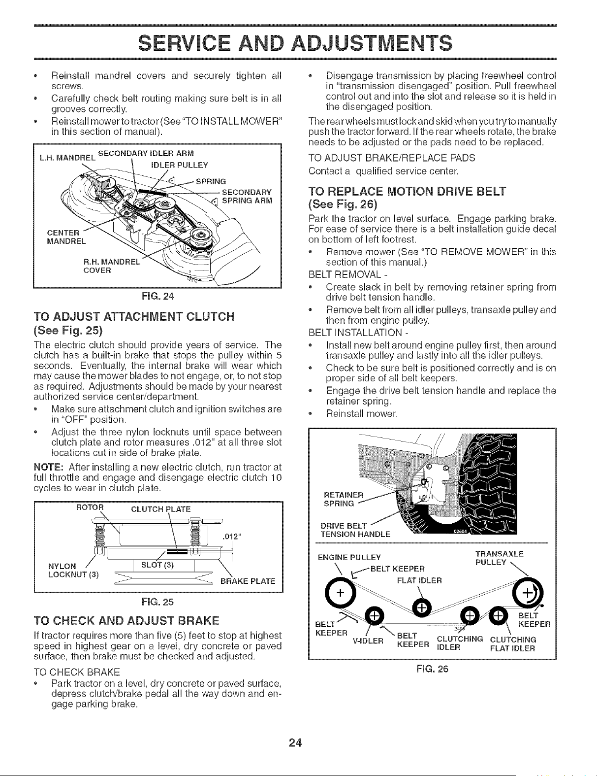
TO REPLACE MOWER DRIVE BELT
MOWER DRIVE BELT REMOVAL (See Fig, 23)
o Park tractor on a level surface, Engage parking
brake,
o Lower mower to its lowest position,
o Disengage belt tention rod from lock bracket,
A
o Remove screws from R,H, mandrel cover and remove
cover,
o Remove any dirt or grass clippings which may have
accumulated around mandreb and entire upper deck
surface,
Disconnect R,H, suspension arm from rear deck bracket
by removing retainer spring,
Roll belt over the top of R,H, mandrel pulby carefully,
o Remove belt from electric clutch pulley,
o Remove belt from idler pulleys,
idler arm and two idlers to see that they
rotate freely,
Be sure spring is securely hooked to primary idler arm
and spring arm,
MOWER DRIVE BELT INSTALLATION (See Fig, 23)
o Install belt in both idlers,
Install new belt onto electric clutch pulby,
Roll belt into upper groove of R,H, mandrel pulley care°
fully,
• Carefully check belt routing making sure belt is in the
grooves correctly,
• Reconnect R,H, suspension arm to rear deck bracket
with retainer spring,
• Reassemble R,H, mandrel cover,
o Engage belt tension rod by pushing rod into locking
bracket,
IDLED
FmG.23
TO REPLACE MOWER BLADE (SECONDARY}
DRIVE BELT (See Fig. 24}
Park the tractor on level surface, Engage parking brake,
Remove mower (See "TO REMOVE MOWER" in this
section of manual),
o Remove screws from R,H, and L,H, mandrel covers
and remove covers,
REMOVE MOWER DRIVE BELT
(Refer to "TO REMOVE MOWER DRIVE BELT" illustration
in this section of manual),
o Carefully roll belt over the top of R,H, mandrel pulley,
o Remove belt from idler pulleys,
o Check primary idler arm and two idlers to see that they
rotate freely,
o Be sure spring is securely hooked to primary idler arm
and spring arm,
REMOVE MOWER BLADE (SECONDARY) DRIVE BELT
o Carefully roll belt off L,H, mandrel pulley,
Remove belt from center mandrel pulley, idler pulley,
and R,H, mandrel pulley,
Remove anydirt or grass which may have accumulated
around mandrels and entire upper deck surface,
Check secondary idler arm and idler pulley to see that
they rotate freely,
Be sure spring is hooked in secondary idler arm and
secondary spring arm,
iNSTALL NEW MOWER BLADE (SECONDARY) DRIVE
BELT
Install new belt in lower groove of R,H, mandrel pulley,
idler pulley, and center mandrel pulley as shown,
Carefully roll belt over L,H, mandrel pulley, Make sure
belt is in all grooves properly,
REINSTALL MOWER DRIVE BELT
(Refer to "TO REMOVE MOWER DRIVE BELT" illustration
in this section of manual),
o Install belt into upper groove of R,H, mandrel pulley
and around both idlers, Pull belt to front of mower to
remove slack,
23
SERVICE AND ADJUSTMENTS
o Reinstali mandrei covers and secureiy tighten air
screws,
o Carefuliy check beit routing making sure beit is in ali
grooves correctiy,
Reinstali mower to tractor (See"TO iNSTALL MOWER"
in this section of manuai),
SECONDARYIDLERARM
L.H. MANDREL
IDLER PULLEY
SECONDARY
SPRING ARM
CENTER
MANDREL
R.H. MANDREL
COVER
FmG.24
TO ADJUST ATTACHMENT CLUTCH
(See Fig. 25)
The eHectrb dutch shouid provide years of service, The
dutch has a buHtqn brake that stops the pulley within 5
seconds, Eventualiy, the internai brake wili wear which
may cause the mower biades to not engage, or, to not stop
as required, Adjustments shouid be made by your nearest
authorized service center/department,
o Make sure attachment dutch and ignition switches are
in "OFF" position,
Adjust the three nyion iocknuts untii space between
dutch prate and rotor measures ,012" at air three shot
iocations cut in side of brake prate,
NOTE: After installing a new electric dutch, run tractor at
fuli throttie and engage and disengage electric dutch 10
cycies to wear in dutch prate,
ROTOR
NYLON/7/ I
LOCKNUT (3)
CLUTCH PLATE
_.012"
/ ' '_ )l
SL, T 3 I "X
BRAKE PLATE
FIG. 25
TO CHECK AND ADJUST BRAKE
if tractor requires more than five (5) feet to stop at highest
speed in highest gear on a ievei, dry concrete or paved
surface, then brake must be checked and adjusted,
TO CHECK BRAKE
Park tractor on a ievei, dry concrete or paved surface,
depress dutch/brake pedai air the way down and en-
gage parking brake,
o Disengage transmission by placing freewheel control
in "transmission disengaged" position, Pull freewheel
control out and into the slot and release so it is held in
the disengaged position,
The rear wheels must lock and skid when you try to manually
push the tractor forward, if the rear wheels rotate, the brake
needs to be adjusted or the pads need to be replaced,
TO ADJUST BRAKE/REPLACE PADS
Contact a qualified service center,
TO REPLACE MOTmON DRIVE BELT
(See Fig. 26}
Park the tractor on ievei surface, Engage parking brake,
For ease of service there is a bert installation guide decai
on bottom of Heftfootrest,
Remove mower (See "TO REMOVE MOWER" in this
section of this manuaL)
BELT REMOVAL -
Create shack in bert by removing retainer spring from
drive bert tension handie,
Remove bert from air idier pulleys, transaxie pulley and
then from engine pulley,
BELT iNSTALLATiON -
o instali new bert around engine pulley first, then around
transaxle pulley and lastly into all the idler pulleys,
o Check to be sure belt is positioned correctly and is on
proper side of all belt keepers,
Engage the drive belt tension handle and replace the
o Reinstall mower,
RETAINER
SPRING
DRIVE BELT
TENSION HANDLE
ENGmNE PULLEY TRANSAXLE
X _BELT KEEPER PULLEY
FLAT IDLER
BELT
BE KEEPER
KEEPER BELT CLUTCHING CLUTCHING
VqDLER KEEPER iDLER FLATIDLER
FIG. 26
24
SERVICE AND ADJUSTMENTS
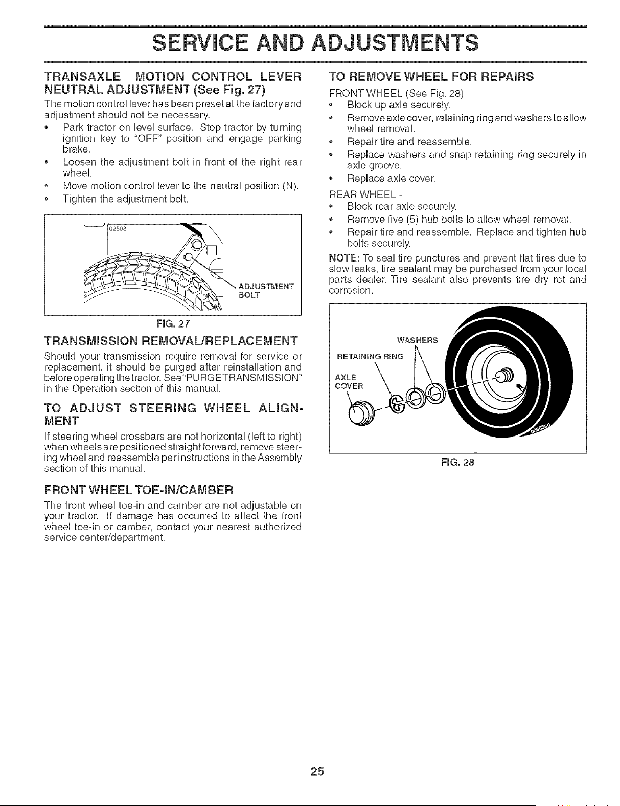
TRANSAXLE MOTmON CONTROL LEVER
NEUTRAL ADJUSTMENT (See Fig. 27)
The motion control Ueverhas been preset at the factory and
adjustment shouUdnot be necessary,
o Park tractor on UeveUsurface, Stop tractor by turning
ignition key to "OFF" position and engage parking
brake,
Loosen the adjustment bout in front of the right rear
wheel
o Move motion control Ueverto the neutral position (N),
o Tighten the adjustment bout,
"*****************J02508 /_
o
TO REMOVE WHEEL FOR REPAmRS
FRONT WHEEL (See Fig, 28)
BUockup axUe securely,
Remove axUecover, retaining ring and washers to allow
wheel removal,
o Repair tire and reassemble,
Replace washers and snap retaining ring securely in
axle groove,
Replace axle cover,
REAR WHEEL -
Block rear axle securely,
Remove five (5) hub bolts to allow wheel removal,
Repair tire and reassemble, Replace and tighten hub
bolts securely,
NOTE: To seal tire punctures and prevent flat tires due to
slow leaks, tire sealant may be purchased from your local
parts dealer, Tire sealant also prevents tire dry rot and
corrosion.
FIG. 27
TRANSMmSSmON REMOVAUREPLACEMENT
Should your transmission require removal for service or
replacement, it should be purged after reinstallation and
before operating the tractor, See"PURGETRANSMISSION"
in the Operation section of this manual,
TO ADJUST STEERmNG WHEEL ALmGN-
MENT
If steering wheel crossbars are not horizontal (left to right)
when wheels are positioned straight forward, remove steer-
ing wheel and reassemble per instructions in the Assembly
section of this manual,
WASHERS
RETAINING RING
AXLE
COVER
FIG. 28
FRONT WHEEL TOEqN/CAMBER
The front wheel toe-in and camber are not adjustable on
your tractor, if damage has occurred to affect the front
wheel toe-in or camber, contact your nearest authorized
service center/department,
25
SERVICE AND ADJUSTMENTS
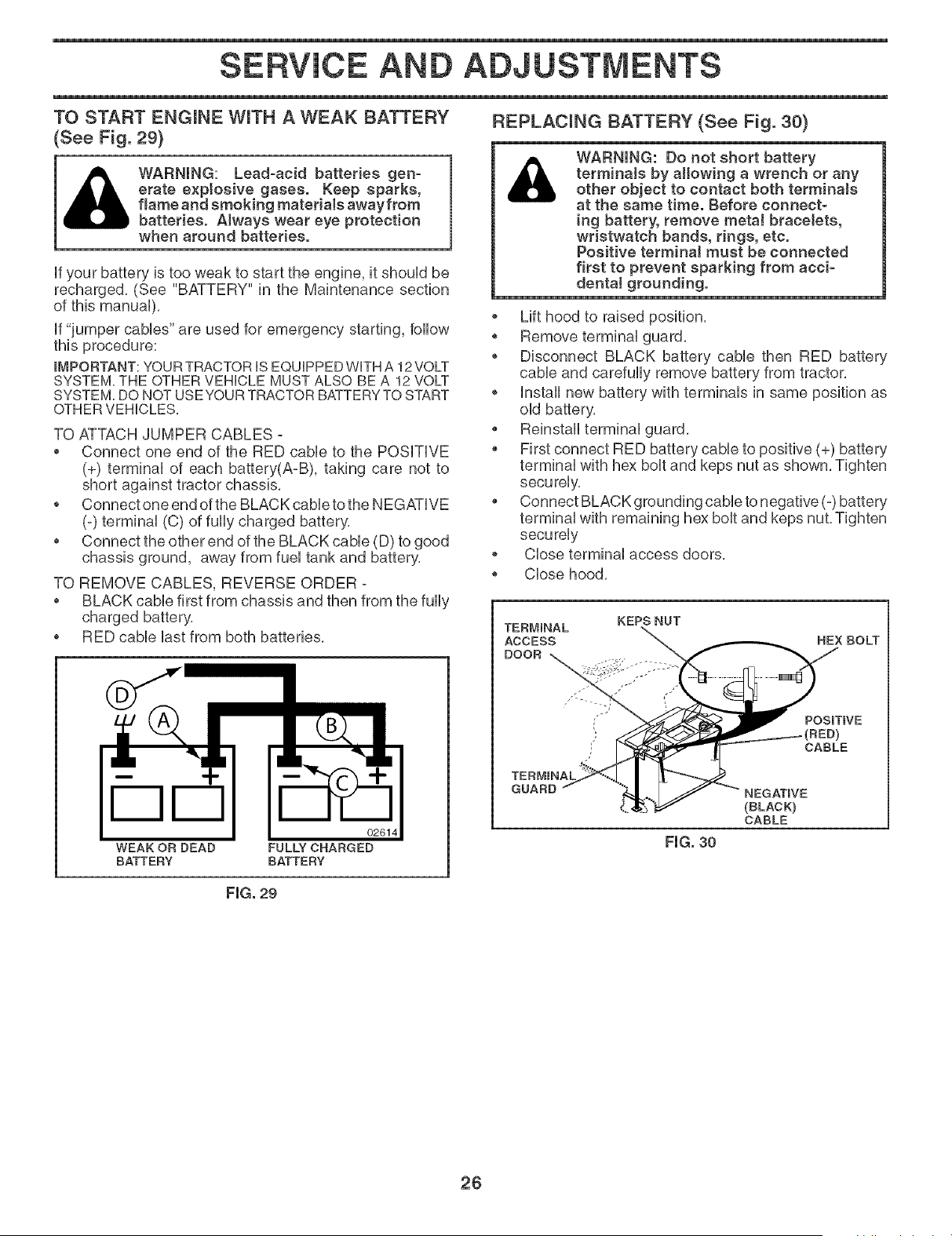
TO START ENGmNE WITH A WEAK BATTERY
(Bee Fig. 29)
_tb) WARNHNG: Lead-acid batteries gen-
erate e×ptoeive gases. Keep sparks,
flame and smoking materials awayfrom
batteries. Always wear eye protection
when around batteries.
if your battery is too weak to start the engine, it should be
recharged, (See "BATTERY" in the Maintenance section
if "jumper cables" are used for emergency starting, follow
this procedure:
_MPORTANT: YOUR TRACTOR iS EQUIPPED WiTH A 12 VOLT
SYSTEM. THE OTHER VEHICLE MUST ALSO BE A 12 VOLT
SYSTEM. DO NOT USEYOUR TRACTOR BATTERY TO START
OTHER VEHICLES.
TO ATTACH JUMPER CABLES -
Connect one end of the RED cable to the POSiTiVE
(+) terminal of each battery(A-B), taking care not to
short against tractor chassis,
o Connect one end of the BLACK cable to the NEGATIVE
(-) terminal (C) of fully charged battery,
Connect the other end of the BLACK cable (D) to good
chassis ground, away from fuel tank and battery,
TO REMOVE CABLES, REVERSE ORDER -
BLACK cable first from chassis and then from the fully
charged battery,
o RED cable last from both batteries,
DD
02614
WEAK OR DEAD FULLY CHARGED
BATTERY BATTERY
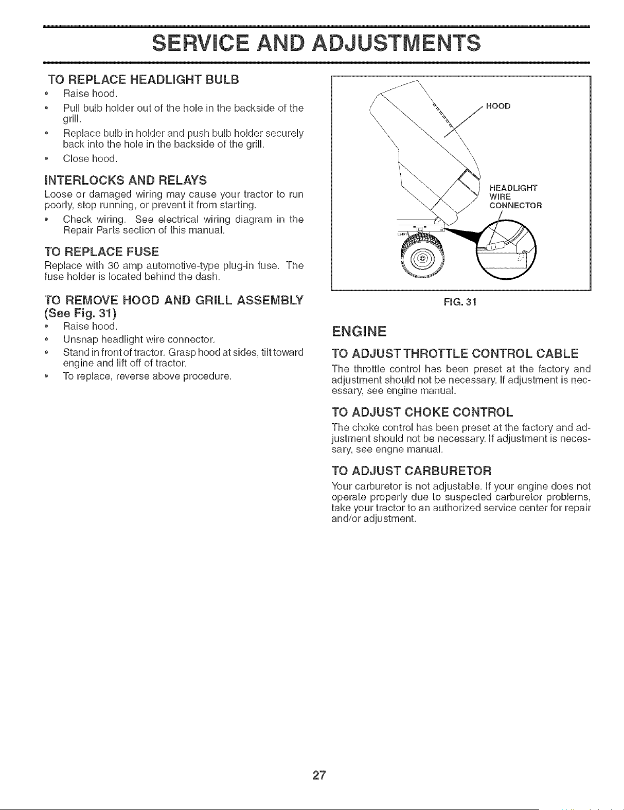
REPLACmNG BATTERY (See Fig. 30)
_1) WARNING: Do not short battery
terminate by allowing a wrench or any
other object to contact both terminaJs
at the same time. Before connect-
ing battery, remove metaJ bracelets,
wristwatch bands, rings, etc.
Positive terminal must be connected
first to prevent sparking from acci-
dental grounding.
o Lift hood to raised position,
o Remove terminal guard,
o Disconnect BLACK battery cable then RED battery
cable and carefully remove battery from tractor,
o Install new battery with terminals in same position as
old battery,
Reinstall terminal guard,
First connect RED battery cable to positive (+) battery
terminal with hex bolt and keps nut as shown, Tighten
securely,
Connect BLACK grounding cable to negative (-) battery
terminal with remaining hex bolt and keps nut, Tighten
securely
o Close terminal access doors,
o Close hood,
KEPS NUT
HEX BOLT
POSmTmVE
CABLE
(BLACK)
CABLE
FmG.30
FmG.29
26
SERVICE AND ADJUSTMENTS
TO REPLACE HEADMGHT BULB
• Raise hood,
o Pull buUbhoUder out of the hoUein the backside of the
grHL
• RepUace buUbin hoUderand push buUbhoUder secureUy
back into the hoUein the backside of the grill
• CUosehood,
mNTERLOCKS AND RELAYS
Loose or damaged wiring may cause your tractor to run
poorUy,stop running, or prevent it from starting,
o Check wiring, See eUectricaUwiring diagram in the
Repair Parts section of this manual
TO REPLACE FUSE
RepUace with 30 amp automotive-type pUug=infuse, The
fuse hoUderis Uocated behind the dash,
HOOD
HEADUGHT
WIRE
CONNECTOR
TO REMOVE HOOD AND GRILL ASSEMBLY
(See Fig. 3t}
• Raise hood,
• Unsnap headlight wire connector,
• Stand in front of tractor, Grasp hood at sides, tilt toward
engine and lift off of tractor,
• To replace, reverse above procedure,
FIG. 31
ENGINE
TO ADJUST THROTTLE CONTROL CABLE
The throttle control has been preset at the factory and
adjustment should not be necessary, if adjustment is nec-
essary, see engine manual,
TO ADJUST CHOKE CONTROL
The choke control has been preset at the factory and ad=
justment should not be necessary, If adjustment is neces-
sary, see engne manual,
TO ADJUST CARBURETOR
Your carburetor is not adjustable, If your engine does not
operate properly due to suspected carburetor problems,
take your tractor to an authorized service center for repair
27
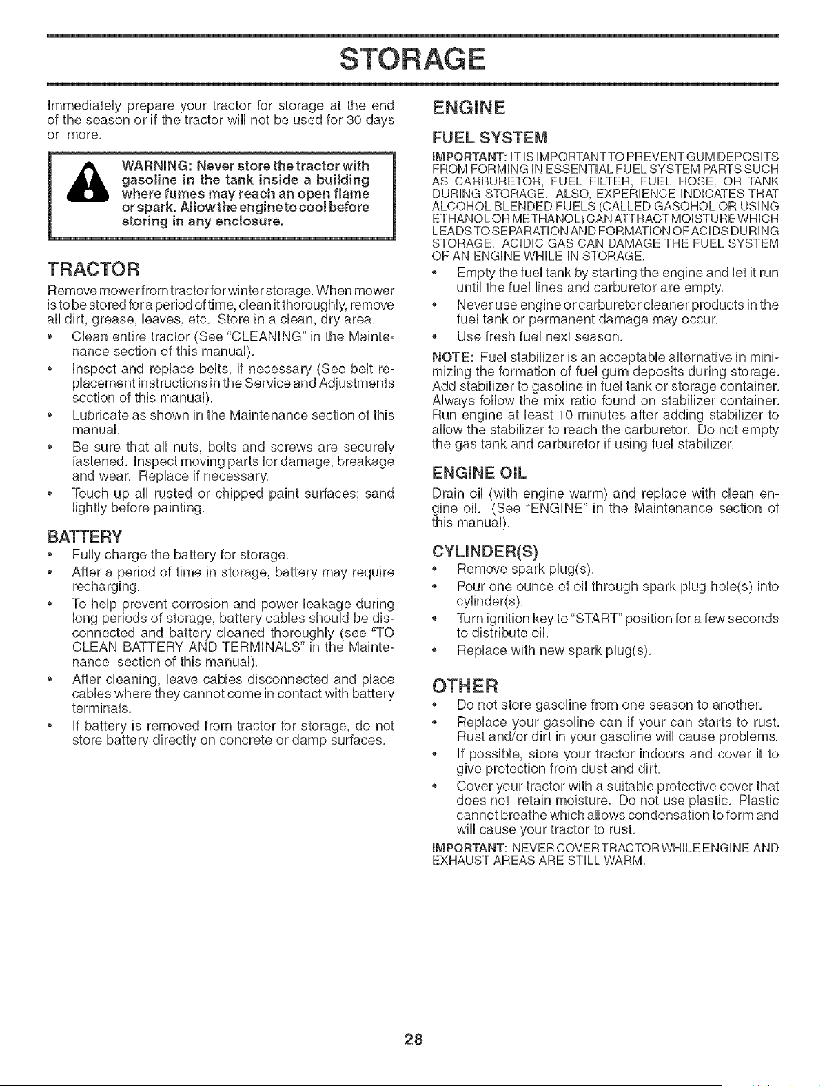
Immediately prepare your tractor for storage at the end
of the season or if the tractor will not be used for 30 days
or more.
WARNING: Never store the tractor with
gasoline in the tank inside a building
where fumes may reach an open flame
or spark. Atlow the engine to cool before
storing in any enclosure.
Remove mower from tractor for winter storage, When mower
is to be stored fora period of time, clean it thorougHy, remove
all dirt, grease, haves, etc, Store in a dean, dry area,
Cban entire tractor (See "CLEANING" in the Mainte-
nance section of this manual),
o inspect and replace belts, if necessary (See belt re-
placement instructions in the Service and Adjustments
section of this manual),
Lubricate as shown in the Maintenance section of this
manual,
Be sure that all nuts, bolts and screws are securely
fastened, Inspect moving parts for damage, breakage
and wear, Replace if necessary,
o Touch up all rusted or chipped paint surfaces; sand
lightly before painting,
BATTERY
Fully charge the battery for storage,
After a period of time in storage, battery may require
recharging,
To help prevent corrosion and power leakage during
long periods of storage, battery cables should be dis-
connected and battery cleaned thoroughly (see "TO
CLEAN BATTERY AND TERMINALS" in the Mainte-
nance section of this manual),
After cleaning, leave cables disconnected and place
cables where they cannot come in contact with battery
terminals,
o If battery is removed from tractor for storage, do not
store battery directly on concrete or damp surfaces,
ENGINE
FUEL SYSTEM
IMPORTANT: ITIS IMPORTANTTOPREVENTGUM DEPOSITS
FROM FORMING INESSENTIAL FUEL SYSTEM PARTSSUCH
AS CARBURETOR, FUEL FILTER, FUEL HOSE, OR TANK
DURING STORAGE. ALSO, EXPERIENCE INDICATESTHAT
ALCOHOL BLENDED FUELS (CALLED GASOHOL OR USING
ETHANOLOR METHANOL) CAN ATTRACTMOISTUREWHICH
LEADSTOSEPARATIONAND FORMATIONOFACDS DURING
STORAGE. ACIDIC GAS CAN DAMAGETHE FUEL SYSTEM
OF AN ENGINE WHILE IN STORAGE.
o Empty the fuel tank by starting the engine and let it run
until the fuel lines and carburetor are empty,
Never use engine or carburetor cleaner products in the
fuel tank or permanent damage may occur,
Use fresh fuel next season,
NOTE: Fuel stabilizer is an acceptable alternative in mini°
mizing the formation of fuel gum deposits during storage,
Add stabilizer to gasoline in fuel tank or storage container,
Always follow the mix ratio found on stabilizer container,
Run engine at least 10 minutes after adding stabilizer to
allow the stabilizer to reach the carburetor, Do not empty
the gas tank and carburetor if using fuel stabilizer,
ENGINE OIL
Drain oil (with engine warm) and replace with clean en-
gine oil, (See "ENGINE" in the Maintenance section of
this manual),
CYUNDER(S)
Remove spark plug(s),
Pour one ounce of oil through spark plug hob(s) into
cylinder(s),
o Turn ignition key to"START" position for a few seconds
to distribute oil,
o Replace with new spark plug(s),
Do not store gasoline from one season to another,
Replace your gasoline can if your can starts to rust,
Rust and/or dirt in your gasoline will cause problems,
if possible, store your tractor indoors and cover it to
give protection from dust and dirt,
o Cover your tractor with a suitable protective cover that
does not retain moisture, Do not use plastic, Plastic
cannot breathe which allows condensation to form and
will cause your tractor to rust,
IMPORTANT: NEVERCOVERTRACTORWHILE ENGINE AND
EXHAUST AREAS ARE STILL WARM.
28

G
PROBLEM
Will not start
Hard to start
Engine will not turn over
Engine cricks but will not
start
Loss of power
Excessive vibration
CAUSE
1. Out of fuel.
2. Engine not"CHOKED" properly.
3= Engine flooded.
4. Bad spark plug.
5. Dirty air filter.
6= Dirty fuel filter.
7= Water in fuel=
8. Loose or damaged wiring.
9. Carburetor out of adjustment.
10= Engine valves out of adiustment=
11. Extreme cold conditions.
1. Dirty air filter.
2= Bad spark plug.
3= Weak or dead battery.
4= Dirty fuel filter.
5= Stale or dirty fuel.
6= Loose or damaged wiring.
7= Carburetor out of adjustment.
8. Engine valves out of adjustment.
1= Brake pedal not depressed.
2. Attachment clutch is engaged.
3. Weak or dead battery.
4. Blown fuse.
5. Corroded battery terminals.
6. Loose or damaged wiring.
7. Faulty ignition switch.
8. Faulty solenoid or starter.
9. Faulty operator presence switch(es).
1. Weak or dead battery.
2. Corroded battery terminals.
3. Loose or damaged wiring.
4. Faulty solenoid or starter.
1. Cutting too much grass/too fast.
2. Throttle in"CHOKE" position.
3. Build-up of grass, leaves and trash under mower.
4. Dirty air filter.
5. Low oi! level/dirty oil.
6. Faulty spark plug.
7. Dirty fuel filter.
8. Stale or dirty fuel.
9. Water in fuel.
10. Spark plug wire loose.
11. Dirty engine air screen/fins.
12. Dirty/clogged muffler.
13. Loose or damaged wiring.
14. Carburetor out of adjustment.
15. Engine valves out of adjustment.
1. Worn, bent or loose blade.
2. Bent blade mandrel.
3. Loose/damaged part(s).
CORRECTION
1= Fill fuel tank.
2. See "TO START ENGINE" in Operation section.
3. Wait several minutes before attempting to start.
4. Replace spark plug.
5. Clean/replace air filter.
6. Replace fuel filter.
7. Empty fuel tank and carburetor, refill tank with fresh
gasoline and replace fue! filter.
8. Check all wiring.
9. See "To Adjust Carburetor" in Service Adiustments
section.
10. Contact an authorized service center/department.
11. See "To start engine" in operation section
1= Clean/replace air filter.
2. Replace spark plug.
3. Recharge or replace battery.
4. Replace fuel filter.
5. Empty fuel tank and refill tank with fresh, clean gasoline.
6. Check all wiring.
7. See "To Adjust Carburetor" in Service Adiustments
section.
8. Contact an authorized service center/departmenL
1= Depress brake peda!.
2. Disengage attachment clutch.
3. Recharge or replace battery.
4. Replace fuse.
5. Clean battery terminals.
6. Check all wiring.
7. ChecWreplace ignition switch.
8. Check/replace solenoid or starter.
9. Contact an authorized service center/departmenL
1= Recharge or replace battery.
2. Clean battery terminals.
3. Check all wiring.
4. ChecWreplace solenoid or starter.
1= Raise cutting height/reduce speed.
2. Adiust throttle control.
3. Clean underside of mower housing.
4. Clean/replace air filter.
5. Check oi! level/change oil.
6. Clean and regap or change spark plug.
7. Replace fuel filter.
8. Empty fuel tank and refill tank with fresh, clean gasoline.
9. Empty fuel tank and carburetor, refill tank with fresh
gasoline and replace fuel filter.
10. Connect and tighten spark plug wire.
11. Clean engine air screen/fins.
12. Clean/replace muffler.
13. Check all wiring.
14. See "To Adjust Carburetor" in Service Adjustments
section.
15. Contact an authorized service center/department.
1= Replace blade. Tighten blade bolt.
2. Replace blade mandrel.
3. Tighten loose part(s). Replace damaged parts.
29

G
PROBLEM
Engine continues to run
when operator leaves seat
with attachment cButch
engaged
PooPcut=uneven
Mower blades will not
rotate
Poor grass discharge
Headlight(s} not working
(if so equipped]
Battery will not charge
Loss of drive
Engine "backfires" when
turning engine "OFF"
CAUSE
1. Faulty operator-safety presence control system.
1. Worn, bent or loose blade.
2. Mower deck not level.
3. Buildup of grass, leaves, and trash under mower.
4. Bent blade mandrel.
5. Clogged mower deck vent holes from buildup of
grass, leaves, and trash around mandrels.
1. Obstruction in clutch mechanism.
2. Worn/damaged mower drive belt.
3. Frozen idler pulley.
4. Frozen blade mandrel.
1. Engine speed too slow.
2. Travel speed too fast.
3. Wet grass.
4. Mower deck not leve!.
5. Low/uneven tire air pressure.
6. Worn, bent or loose blade.
7. Buildup of grass, leaves and trash under mower.
8. Mower drive belt worn.
9. Blades improperly installed.
10. Improper blades used.
11. Clogged mower deck vent holes from buildup of
grass, leaves, and trash around mandrels.
1. Switch is"OFF".
2. Bulb(s) or lamp(s) burned out.
3. Faulty light switch.
4. Loose or damaged wiring.
5. Blown fuse.
1. Bad battery cell(s).
2. Poor cable connections.
3. Faulty regulator (if so equipped).
4. Faulty alternator.
1. Freewheel control in "disengaged" position.
2. Motion drive belt worn, damaged, or broken.
3. Air trapped in transmission during shipment
or servicing.
1. Engine throttle contro! not set between half and
full speed (fast) position before stopping engine.
CORRECTION
1. Check wiring, switches and connections. If not
corrected, contact an authorized service center/
department.
1. Replace blade. Tighten blade bolt.
2. Level mower deck.
3. Clean underside of mower housing.
4. Replace blade mandrel.
5. Clean around mandrels to open vent holes.
1. Remove obstruction.
2. Replace mower drive belt.
3. Replace idler pulley.
4. Replace blade mandrel.
1. Place throttle control in"FAST" position.
2. Shift to slower speed.
3. Allow grass to dry before mowing.
4. Level mower deck.
5. Check tires for proper air pressure.
6. Replace/sharpen blade. Tighten blade bolt.
7. Clean underside of mower housing.
8. Replace mower drive belt.
9. Reinstall blades sharp edge down.
10. Replace with blades listed in this manual.
11. Clean around mandrels to open vent holes.
1, Turn switch"ON".
2. Replace bulb(s) or lamp(s).
3. Check/replace light switch.
4. Check wiring and connections.
5. Replace fuse.
1. Replace battery.
2. ChecWclean all connections.
3. Replace regulator.
4. Replace alternator.
1. Place freewheel control in "engaged" position.
2. Replace motion drive belt.
3. Purge transmission.
1. Move throttle control between half and full speed
(fast) position before stopping engine.
3O
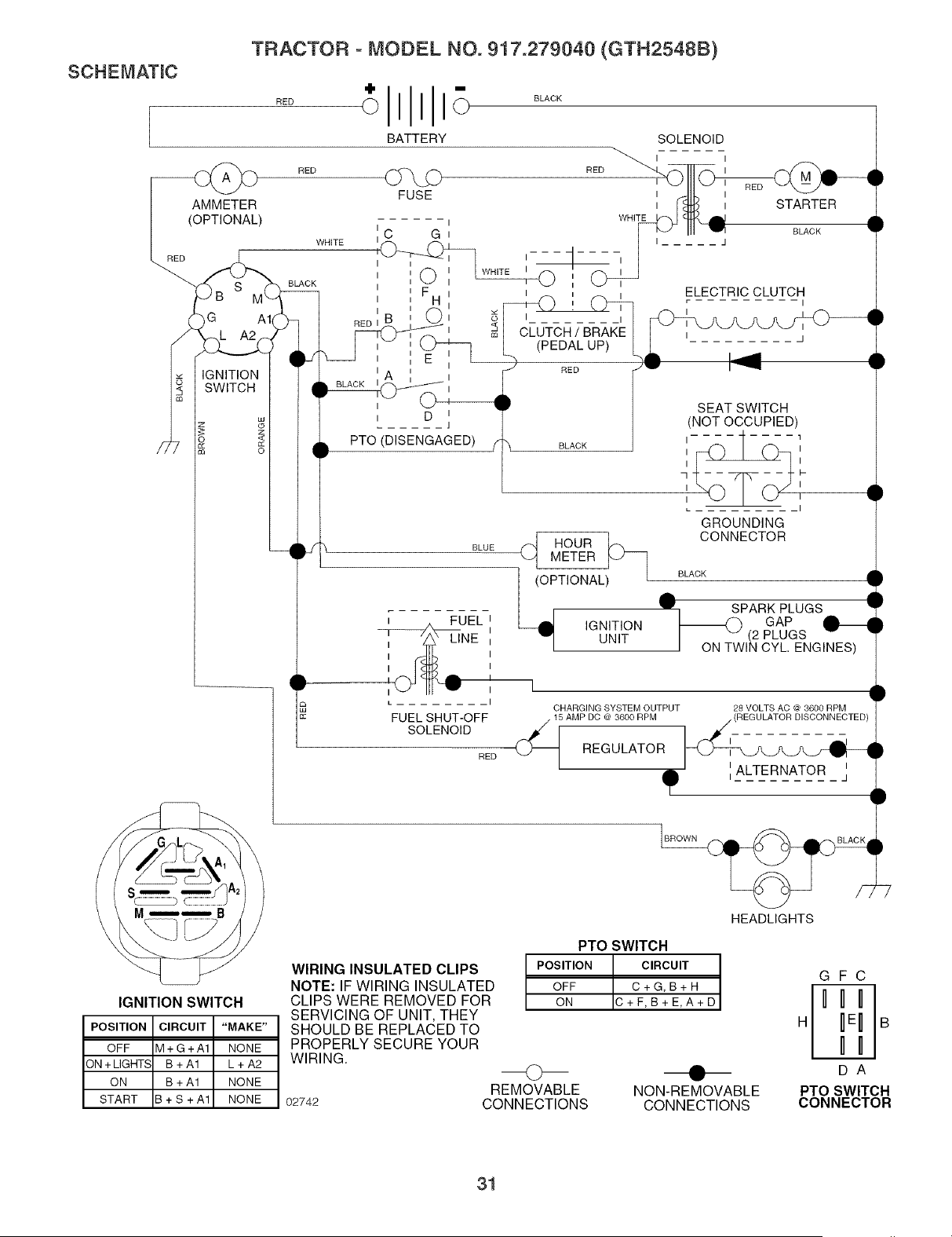
SCHEMATmC
TRACTOR - MODEL NO. 917.279040 (GTH2548B)
RED
BATTERY
BLACK
SOLENOID
AMMETER
(OPTIONAL)
RED
S
G A1
IGNITION
SWITCH
RED _ RED
FUSE
WHITE
BLACK
WHITE
I _1
CLUTCH / BRAKE
(PEDAL UP)
RED
I
i STARTER
BLACK
J
ELECTRIC CLUTCH
I
z
<
I
i D i
..... J
PTO (DISENGAGED)
BLUE
FUEL i
I I
I I
I I
I I
i
I I
L -- I
FUEL SHUT-OFF
SOLENOID
RED
BLACK
_ HOUR
METER
SEAT SWITCH
(NOT OCCUPIED)
, ,
GROUNDING
CONNECTOR
BLACK
A •
Iw SPARK PLUGS I
GAP
I _ (2 PLUGS v ..
I ON TWIN CYL. ENGINES)
i q
OHARGINGSYSTEMOUTPUT _ VOLTSAO_ _00RPM
,AMPDO_ 3600RPM //REGULATOR01SOONNEOTEO/i
REGULATOR __
O I IiALTERNATOR J •
q
)
IGNITION SWITCH
POSITION CIRCUIT "MAKE"
OFF M+G+A1 NONE
3N+LIGHTS B+A1 L+A2
ON B + A1 NONE
START B + S + A1 NONE
7
HEADLIGHTS
WIRING INSULATED CLIPS
NOTE: IF WIRING INSULATED
CLIPS WERE REMOVED FOR
SERVICING OF UNIT, THEY
SHOULD BE REPLACED TO
PROPERLY SECURE YOUR
WIRING.
02742
PTO SWITCH
POSITION CIRCUIT
OFF C+G,B+H
ON C+F,B+E,A+D
©
REMOVABLE
CONNECTIONS
NON-REMOVABLE
CONNECTIONS
GFC
DA
PTO SWITCH
CONNECTOR
31
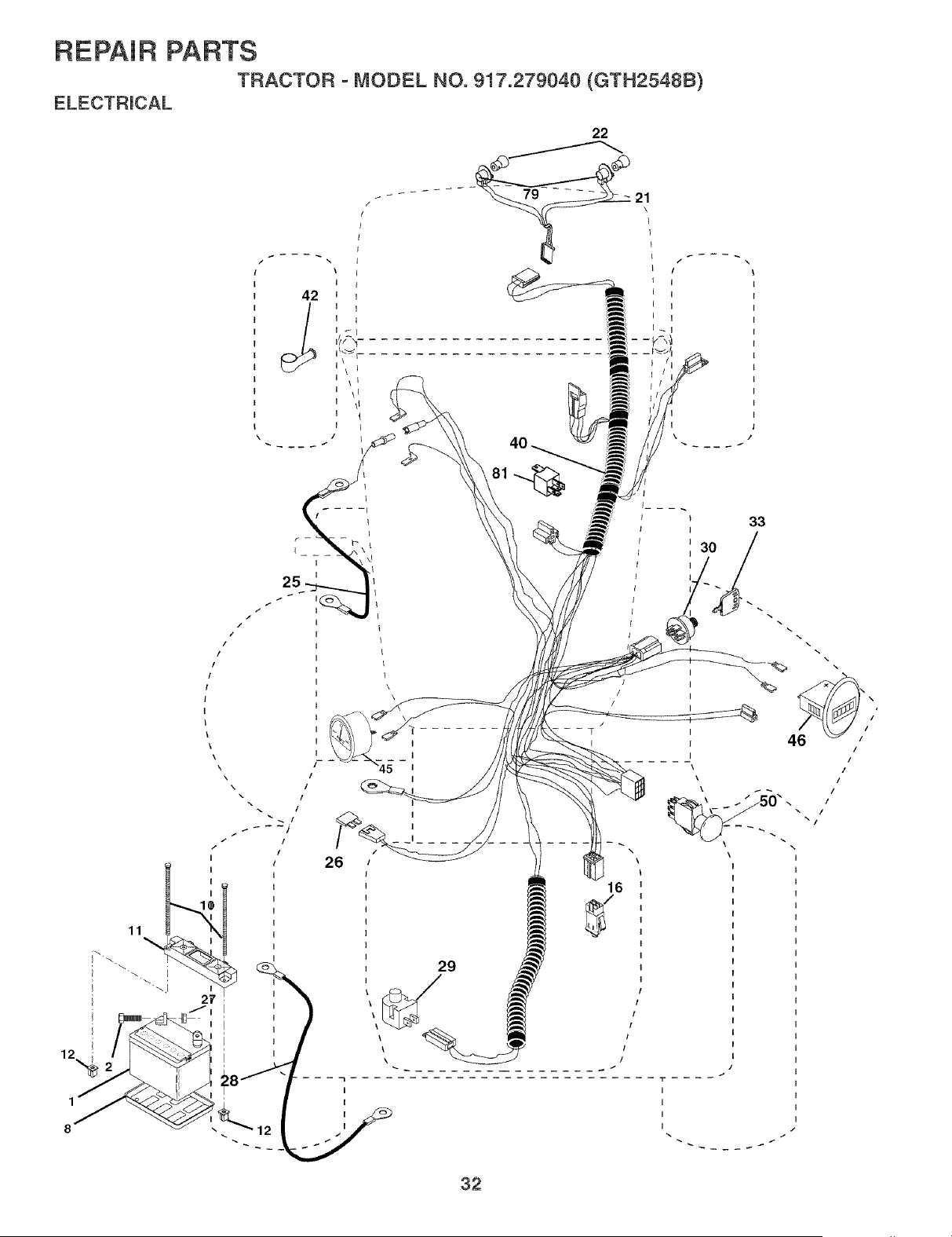
REPAIR PARTS
TRACTOR - MODEL NO. 917.279040 (GTH2548B}
11
27
i JE
12
,%
\
I
42 J
I
I \\ L
I
I \1
I \l
/
26
I
I
I
I
J
T
16
46
\
"1"
I
I
I
I
32
\

REPAIR PARTS
TRACTOR - MODEL NO. 917.279040 (GTH2548B)
KEY PART
NO. NO. DESCRiPTiON
1 532144927 Battery
2 874760412 BoUtHex Head 1/4-20 x 3/4
8 532124886 Tray, Battery
10 532145211 BoUt,Battery Front 1/4-20 x 7,5 Zinc
11 532150109 HoUddown Battery Front Mount
12 532145769 Nut, Push Nybn 1,4" Battery Front
16 532176138 Switch Unterbck Pushqn
21 532175688 Harness Socket Light w/4152J
22 532004152 BuUb
25 532185456 CaMe, Battery
26 532108824 Fuse
27 873510400 Nut Keps Hex 1/4-20
28 532170697 CaMe, Ground
29 532121305 Switch, PUunger NC Gray
30 532175566 Switch, Ugn
33 532140401 Key
40 532188034 Harness Ign,
42 532154336 Cover, Terminal Red
45 532177500 Ammeter
46 532177501 Hourmeter
50 532174651 Switch, PTO
79 532175242 Socket Assembly Bulb
81 532109748 Relay Asm,
NOTE: All component dimensions given in U,S, inches
1 inch = 25,4 mm
33
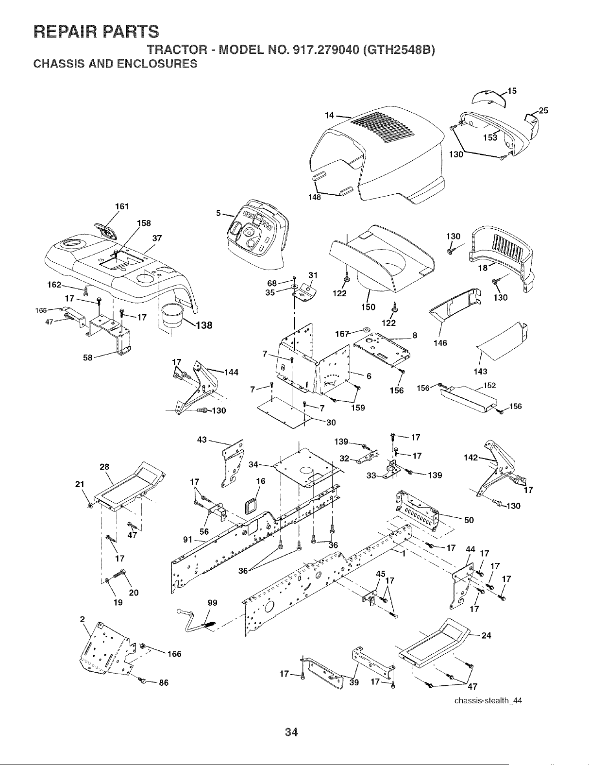
REPAIR PARTS
TRACTOR - MODEL NO. 917.279040 (GTH2548B)
CHASSIS AND ENCLOSURES
161
158
37
122
159
18
130
146
/
156
143
156J_
_156
21
\
2
\
28
17
56
99
86
16
i
45
chassis-stealth 44
34

REPAIR PARTS
TRACTOR - MODEL NO. 917.279040 (GTH2548B)
CHASSIS AND ENCLOSURES
KEY PART
NO. NO. DESCRiPTiON
1 532180375
2 532175282
5 532189025
6 532157882
7 817720408
8 532184668
14 532190055
15 532161841
16 532121794
17 817000612
18 532182873
19 819131312
20 874780616
21 873800600
24 532181058
25 532161842
28 532181057
30 532145052
31 532161419
32 532161327
33 532161326
34 532177018
35 819111116
36 817060512
37 532181720
39 532175278
43 532136939
44 532136940
45 532176018
47 817490608
50 532175476
56 532176016
58 532183569
68 817490508
86 874780720
91 532180374
99 532177143
122 532161464
130 532171875
138 532181798
139 532171873
142 532161897
143 532177586
144 532161900
146 532177587
148 532164655
150 532190309
152 532177956
153 532188212
156 817000512
158 817670608
159 817000612
161 532181787
162 532142432
165 532183554
166 873680700
167 532184672
Rail, Frame RH
Drawbar, Gt
Dash
Dash, 1PCS, Lower
Screw, Thd Cut 1/4-20 x 1/2
Support, Battery
Hood Asm,, Pnt
Lens LH
Cover, Access
Screw, 3/8-16 x 3/4
Grille
Washer 13/32 x 13/16 x 12 Ca,
Bolt, Fin Hex 3/8-16 x 1
Nut, Crownlock 3/8-16
Footrest, RH
Lens RH
Footrest, LH
Saddle
Bracket Supt 1-pc Vgt Steering
Bracket, Frame Pivot Lh
Bracket, Frame Pivot Rh
Plate Asm Engine Chassis
Washer 11/32 x 11/16 x 16 Ca,
Screw 5/16-18 x 3/4
Fender, Pnt,
Bracket, Axle Front
Bracket, Spnsn Front Lh
Bracket, Spnsn Front Rh
Bracket Asm,, Susp Chassis Rh
Screw Thdrol 3/8-16 x 1/2
Bracket, Chassis Front
Bracket Asm,, Susp Chassis Lh
Bracket Asm,, Fender
Screw, 5/16-18 x 1/2
Bolt, Fin Hex 7/16-14 unc x 1-1/4
Rail, Frame Lh
Rod Asm, Bypass
Screw Hex WSHD 8-18 x 7/8
Screw Hw Hd Hi-Lo #13-16 x 3/4
Bolt Shoulder 5/16-18
Bracket Dash Stealth RH
Skirt Grille RH
Bracket Dash Stealth LH
Skirt Grille LH
Extrusion Bumper
Duct Heat Hood
Shield, Browning
Light Box Asm, w/Lens
Screw 5/16-18 x 3/4
Screw 3/8-16 x 1/2
Screw 3/8-16 x 3/4
Console Fuel Window
Screw Hex 1/4ol/2 unc
Bracket Support Tank
Nut, Crown Lock 7/16-14 unc
Bushing Snap
NOTE: All component dimensions given in U,S, inches
1 inch = 25,4 mm
35
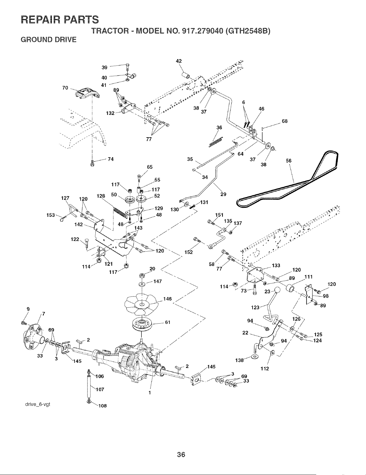
REPAIR PARTS
TRACTOR - MODEL NO. gl 7.279040 (GTH2548B)
GROUND DRIVE
69
33
3
drive 6-vgt
127 120
42
77
36 / 68
120
111
114_. 120
23-
125
_124
112
36

REPAIR PARTS
TRACTOR - MODEL NO. 917.279040 (GTH2548B)
GROUND DRIVE
KEY PART KEY PART
NO. NO. DESCRiPTiON NO. NO. DESCRiPTiON
1 Transaxb Hydro Gear 77 874780716
331°3000 (Order Parts From 89 873680700
Transaxb Manufacturer) 94 532133835
2 532007070 Key Sq, 1/4 x 2,5 98 532141004
3 532007563 Washer 106 532142918
6 876020412 Pin, Cotter 107 532154739
7 532140507 WheeU, Hub AssembUy 108 532142917
9 532140080 BoUt,Hub 111 532156240
20 873940800 Nut 112 532178558
22 532180235 Lever Asm Shift 114 873800500
23 532140845 Knob 117 873900600
29 532176600 Brake, Rod 120 817000612
33 812000053 Ring E 121 532175611
34 532071673 Cap, Parking Brake 122 872010520
35 532137648 Rod, Parking Brake 123 532183254
36 532149412 Spring, Drive Ground 124 532165492
37 532121749 Washer25/32 x 1-1/4 x 16 Ga, 125 817490510
38 532150035 NyHner 126 532166002
39 874321016 Screw, Fin, #10-24 x 1 127 532177362
40 532178575 Actuator, Unterbck VGT 128 532176624
41 873931000 Nut Centerbck 10-24 unc 129 532179473
42 532124872 Cover, PedaU 130 819131016
46 532145170 Retainer, Spring 131 876020312
48 872110614 BoUtRdhd 3/8-16 x 1-3/4 G r, 5 132 532175467
50 532131494 Pulley, UdUer,Fiat 133 532175468
52 532127783 Pulley, UdUer,Grooved 135 532177364
55 532105706 Bearing, UdUer 137 532124949
56 532161597 V-BeUt 138 532001370
58 874760724 BoUtFin Hex 7/16-14 x 1-1/2 142 532175469
61 532143995 Pulley, Transaxb 143 817060512
64 532176601 Shaft, Brake PedaU 145 532163168
65 532179613 BoUt,ShouUder 146 532140462
68 532005142 Pin, Roll 147 532141322
69 532123800 Washer 151 874760514
70 532181788 Consob Automatic YT/GT 152 532178705
73 874490548 Bolt Hex Flghd 5/16-18 x 3 Gr, 5 153 532124788
74 532142432 Screw Hex Wsh, Hi-Lo 1/4-1/2
Bolt Fin Hex 7/16-14 x 1
Nut Crownlock 7/16-14 unc
Fastener Christmas Tree
Bracket Shift
O-Ring Asm Hydro Gear
Line Fuel Hydro 15" VGT
Cap Asm Vent Hydro Gear
Spacer Shift Lever VGTH
Washer Nylon High Temp
Nut Lock Hex W/ins 5/16-18 unc
Nut, Lock Fig, 3/8-16
Screw 3/8-16 x ,75
Bracket Strap Torque
Bolt RDHDSQ 5/16-18 unc x 2-1/2
Rod Shift
Bolt Shoulder 5/16-18 x ,561
Screw 5/16-18 x 5/8
Washer SRRTD 5/16 ID x 1 x ,125
Link Control Clutch
Spring Drive GRND
Bracket Asm Idler Tensioning
Washer 13/32 x 5/8 x 16 Ga,
Pin Cotter 3/32 x 3/4
Bracket Mtg Hydro 3500 LH VGT
Bracket Mtg Hydro 3500 RH VGT
Link Asm Control Hydro 3500
Nut Lock 5/16-18 NC Thd,
Washer Thrust 5/8 x 1,10 x 1/32
Strap Torque HG-3500
Screw Thdrol 5/16-18 x 3/4
Washer Axle Flange HG-3000
Fan 7" Hydro
Washer
Bolt Hex 5/16-18 x 7/8
Bolt Hex 5/16 x 1 W/Patch
Spring, Retainer
NOTE: All component dimensions given in U. S.
inches 1 inch = 25.4 mm
37
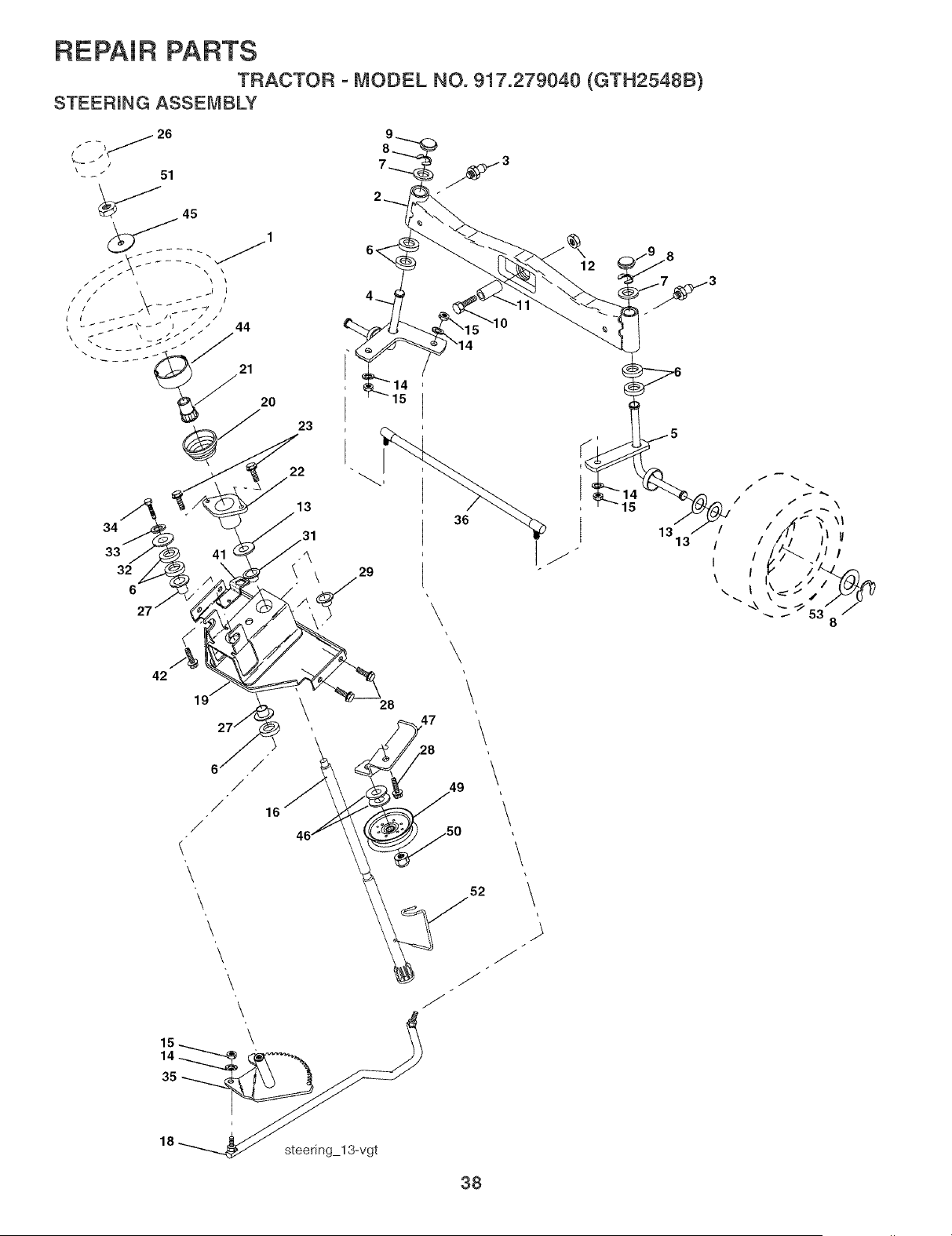
REPAIR PARTS
TRACTOR - MODEL NO. 917.279040 (GTH2548B)
STEEFIING ASSEMBLY
\
47
\
\
18 _ steedng 13_,'gt
\
\
\
\
\
15
13
13
38

REPAIR PARTS
TRACTOR - MODEL NO. 917.279040 (GTH2548B)
STEERING ASSEMBLY
KEY PART
NO. NO. DESCRiPTiON
1 532166627
2 532178557
3 532183226
4 532161849
5 532161848
6 532124931
7 532121748
8 812000029
9 532121232
10 874781044
11 532136518
12 873901000
13 532121749
14 810040600
15 873540600
16 532186814
18 532175572
19 532156011
20 532177592
21 532159945
22 532155105
23 532152927
26 532166626
27 532124937
28 817000612
29 532104239
31 532138136
32 819111610
33 810040500
34 874780512
35 532187039
36 532186799
41 532155246
42 817490508
44 532177593
45 819182411
46 819131610
47 532179471
49 532175820
50 873900600
51 873940800
52 532175553
53 532188967
WheeU, Steering
Axb Asm,, Front
Fitting, Grease
Spindb Asm, LH
Spindb Asm,, RH
Bearing, Race Thrust Harden
Washer 25/32 x 1o5/8 x 16 Ga,
Ring, KHp #T5304°75
Cap, Spindb
BoUt,Fin Hex 5/8oll x 2o3/4
Spacer Brg Axb Front 1,570
Nut, Lock FUange 5/8oll unc
Washer 25/32 x 1ol/4 x 16 Ga,
Washer, Lock Hvy HUcUSpr 3/8
Nut 3/8o24
Shaft Asm,, Steering
DragHnk, BaH Joint Solid Vgt
Support Asm,, Steering Vgt
Boot Steering
Adapter, WheeU Steering
Bushing, Strg,
Screw
Cap, WheeU Steering
Bearing, CoL Strg,
Screw 3/8-16 x 3/4
Bearing, FUange
Bushing, NyHner Snap
Washer 11/32 x 1 x 10 Ga,
Washer, Lock Hvy HbUSpr 5/16
BoUt,Hex Hd 5/16-18 x 3/4
Gear, Sector Steering
Tie Rod
Bracket Switch Unerbck VGT97
Screw 5/16-18 x 1/2
Extension Steering Premium
Washer 13/32 x 1-1/20 x 11 Ga,
Washer Flat 13/32 x 1 x 10 Ga,
Bracket Asm, Idler
Pulley Idler Flat
Nut Lock Fig 3/8-16 unc
Nut Hex Jam Toplock 1/2-20 unc
Clip Steering
Washer Harden
NOTE: All component dimensions given in U,S, inches
1 inch = 25,4 mm
39
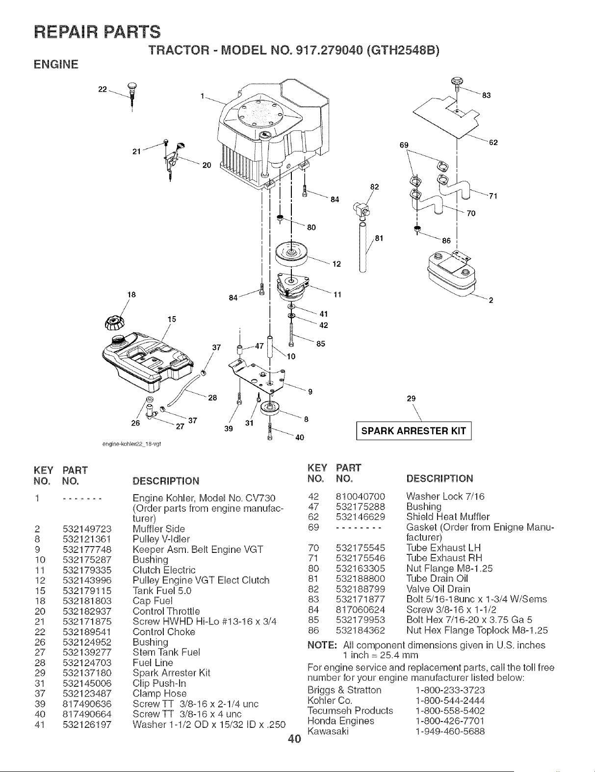
REPAIR PARTS
TRACTOR - MODEL NO. 917.279040 (GTH2548B)
ENGINE
21
18
84
26 27 39 31
engine-kohbr22 18-vgt
80
i
42
85
82
12 I/81
69
i
i
I
_2
29
\
I SPARK ARRESTER KIT I
KEY
NO.
2
8
9
10
11
12
15
18
2O
21
22
26
27
28
29
31
37
39
4O
41
PART
NO.
532149723
532121361
532177748
532175287
532179335
532143996
532179115
532181803
532182937
532171875
532189541
532124952
532139277
532124703
532137180
532145006
532123487
817490636
817490664
532126197
DESCRIPTION
Engine Kohler, Model No, CV730
(Order parts from engine manufac-
turer)
Muffler Side
Keeper Asm, Belt Engine VGT
Bushing
Clutch Electric
Pulley Engine VGT Elect Clutch
Tank Fuel 5,0
Cap Fuel
Control Throttle
Screw HWHD Hi-Lo #13-16 x 3/4
Control Choke
Bushing
Stem Tank Fuel
Fuel Line
Spark Attester Kit
Clip Pushdn
Clamp Hose
Screw TT 3/8-16 x 2-1/4 unc
Screw TT 3/8-16 x 4 unc
Washer 1-1/20D x 15/32 ID x ,250
4O
KEY PART
NO. NO. DESCRIPTION
42 810040700
47 532175288
62 532146629
69
70 532175545
71 532175546
80 532163305
81 532188800
82 532188799
83 532171877
84 817060624
85 532179953
86 532184362
Washer Lock 7/16
Bushing
Shield Heat Muffler
Gasket (Order from Enigne Manu-
facturer)
Tube Exhaust LH
Tube Exhaust RH
Nut Flange M8-1,25
Tube Drain Oil
Valve Oil Drain
Bolt 5/16-18unc x 1-3/4 W/Sems
Screw 3/8-16 x 1-1/2
Bolt Hex 7/16-20 x 3,75 Ga 5
Nut Hex Flange Toplock M8-1,25
NOTE: All component dimensions given in U,S, inches
1 inch = 25,4 mm
For engine service and replacement parts, call the toll free
number for your engine manufacturer listed below:
Briggs & Stratton 1-800-233-3723
Kohler Co, 1-800-544-2444
Tecumseh Products 1-800-558-5402
Honda Engines 1-800-426-7701
Kawasaki 1-949-460-5688
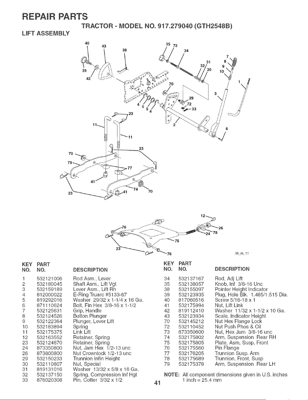
REPAIR PARTS
TRACTOR - MODEL NO. 917.279040 (GTH2548B)
LmFT ASSEMBLY
40 43 35 73
32/30
42 _. 70
3\
7O
23
23
7O
KEY PART
NO. NO.
1 532121006
2 532180045
3 532159189
4 812000022
5 819292016
6 871110624
7 532125631
8 532124526
9 532122364
10 532183894
11 532175375
12 532163552
23 532124670
24 873350800
26 873800800
29 532150233
30 532110807
31 819131016
32 532137150
33 876020308
12_
__76 ____._ _,--_ 26
lift rh 11
DESCRIPTION
KEY PART
NO. NO. DESCRIPTION
Rod Asm,, Lever
Shaft Asm,, Lift Vgt
Lever Asm,, Lift Rh
E-Ring Truarc #5133-87
Washer 29/32 x 1-1/4 x 16 Ga,
BoUt,Fin Hex 3/8-16 x 1-1/2
Grip, HandUe
Button PUunger
PUunger, Lever Lift
Spring
Link Lift
Retainer, Spring
Retainer, Spring
Nut, Jam Hex 1/2-13 unc
Nut Crownbck 1/2-13 unc
Trunnion UnfinHeight
Nut, SpeciaU
Washer 13/32 x 5/8 x 16 Ga,
Spring, Compression UnfHgt
Pin, Cotter 3/32 x 1/2
34 532137167
35 532138057
38 532155097
39 532123935
40 817060516
41 532175994
42 819112410
43 532123934
70 532145212
72 532110452
73 873350600
74 532175802
75 532175805
76 532175560
77 532176205
78 532175689
79 532175378
Rod, Adj Lift
Knob, Unf 3/8=16 Unc
Pointer Height Undicator
PUug,HoUeBUk, 1,485/1,515 Dia,
Screw 5/16-18 x 1
Nut, Lift Link
Washer 11/32 x 1-1/2 x 10 Ga,
ScaUe, Undicator Height
Nut Hex Flange Lock
Nut Push Phos & Oil
Nut, Hex Jam 3/8-16 unc
Arm, Suspension Rear RH
Plate, Asm, Susp, Front
Pin Flange
Trunnion Susp, Arm
Trunnion, Front, Susp
Arm, Suspension Rear LH
NOTE: All component dimensions given in U,S, inches
1 inch = 25,4 mm
41
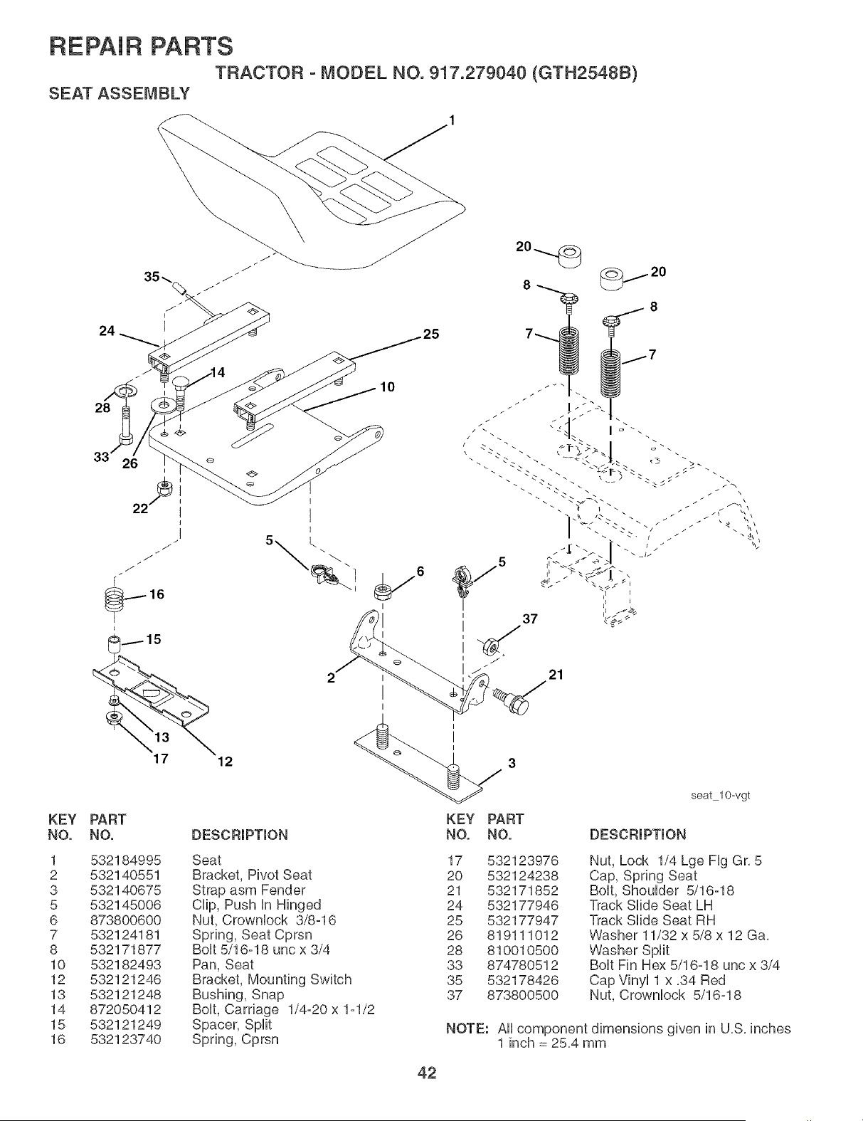
REPAIR PARTS
TRACTOR - MODEL NO. 917.279040 (GTH2548B)
SEAT ASSEMBLY
24
28
33' 26
KEY PART
NO. NO.
1 532184995
2 532140551
3 532140675
5 532145006
6 873800600
7 532124181
8 532171877
10 532182493
12 532121246
13 532121248
14 872050412
15 532121249
16 532123740
17
12
DESCRIPTION
10
21
I
I
I
KEY
NO.
Seat
Bracket, Pivot Seat
Strap asm Fender
CHp, Push in Hinged
Nut, Crownbck 3/8-16
Spring, Seat Cprsn
BoUt5/16-18 unc x 3/4
Pan, Seat
Bracket, Mounting Switch
Bushing, Snap
BoUt,Carriage 1/4-20 x 1-1/2
Spacer, Split
Spring, Cprsn
PART
NO. DESCRIPTION
seat 10-vgt
17 532123976
20 532124238
21 532171852
24 532177946
25 532177947
26 819111012
28 810010500
33 874780512
35 532178426
37 873800500
Nut, Lock 1/4 Lge Fig Gr, 5
Cap, Spring Seat
Bolt, Shoulder 5/16-18
Track Slide Seat LH
Track Slide Seat RH
Washer 11/32 x 5/8 x 12 Ga,
Washer Split
Bolt Fin Hex 5/16-18 unc x 3/4
Cap Vinyl 1 x ,34 Red
Nut, Crownlock 5/16-18
NOTE: All component dimensions given in U,S, inches
1 inch = 25,4 mm
42
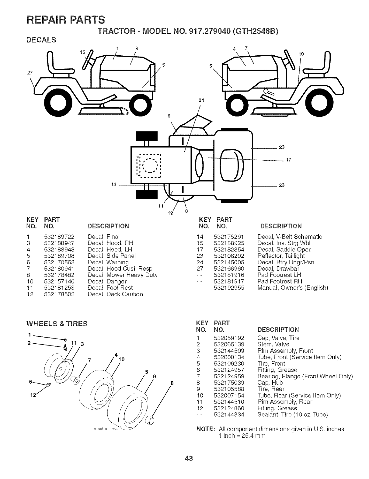
REPAIR
DECALS
27
PARTS
TRACTOR - MODEL NO. 917.279040 (GTH2548B)
15
4 7
5 5
10
24
23
17
14
23
KEY PART
NO. NO.
1 532189722
3 532188947
4 532188948
5 532189708
6 532170563
7 532180941
8 532178482
10 532157140
11 532181253
12 532178502
11
12 8
KEY PART
DESCRIPTION NO. NO.
Decal, Final 14 532175291
Decal, Hood, RH 15 532188925
Decal, Hood, LH 17 532182854
Decal, Side Panel 23 532106202
DecaH,Warning 24 532145005
DecaH,Hood Cust. Resp. 27 532166960
DecaH,Mower Heavy Duty - - 532181916
DecaH,Danger -- 532181917
DecaH,Foot Rest - - 532192955
Decal Deck Caution
DESCRIPTION
Decal ins. Strg Whi
Decal Saddle Oper.
Reflector, TaHHght
Decal Btry Dngr/Psn
Decal Drawbar
Pad Footrest LH
Pad Footrest RH
Manual Owner's (English)
WHEELS & TIRES
2 3
4
10
wheel art l-vgt
5
9
KEY PART
NO. NO.
1 532059192
2 532065139
3 532144509
4 532008134
5 532106230
6 532124957
7 532124959
8 532175039
9 532105588
10 532007154
11 532144510
12 532124860
== 532144334
DESCRIPTION
Cap, Vaive, Tire
Stem, Vaive
Rim Assembiy, Front
Tube, Front (Service item Oniy)
Tire, Front
Fitting, Grease
Bearing, Flange (Front Wheel Only)
Cap, Hub
Tire, Rear
Tube, Rear (Service item Only)
Rim Assembly, Rear
Fitting, Grease
Sealant, Tire (10 oz. Tube)
NOTE: All component dimensions given in U.S. inches
1 inch = 25.4 mm
43
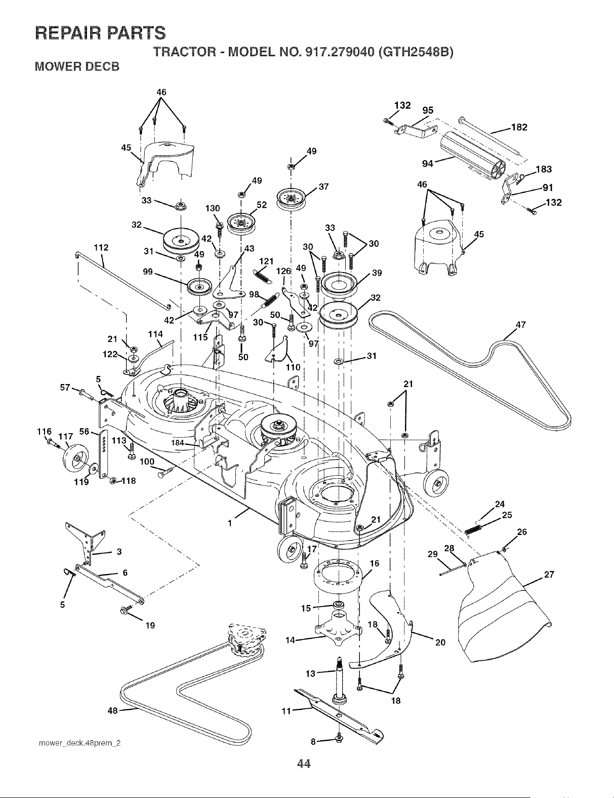
REPAIR PARTS
TRACTOR - MODEL NO. 917.279040 (GTH2548B)
MOWER DECB
112
46
21 114 I 1
I
122., 50
110 I
33
132 95
15
18
29
26
44

REPAIR PARTS
TRACTOR - MODEL NO. 917.279040 (GTH2548B)
MOWER DECK
KEY PART KEY PART
NO. NO. DESCRiPTiON NO. NO. DESCRiPTiON
1
3
5
6
8
11
13
14
15
16
17
18
19
2O
21
24
25
26
27
28
29
3O
31
32
33
37
39
42
43
45
46
47
48
49
532181848
532178915
532124670
532178024
532174365
532173921
532180054
532174360
532174358
532110485
532174493
872110610
872140505
532132827
532174378
873680500
532105304
532178102
532110452
532181707
819111016
532131491
532173984
532187690
532173436
532178342
532177968
532174375
532122052
532174373
532180806
532137729
532180808
532174368
873900600
Deck Weidment Mower 48 50
Bracket Asm,, Sway Bar 52
Retainer Spring 56
Sway Bar Deck 57
Boit 7/16 Asm, Biade 91
(The following biades are avaHabie) 94
Biade, 48" Muiching (For muiching 95
mowers onHy) 97
Biade, 48" Hi-Lift (For bagging and 98
discharging) 99
Shaft Asm, w/Lower Bearing 100
Mandrei Asm, 110
Bearing, BaH, Mandrei 112
Stripper Mandrei Deck 113
Boit RDHD Sq Neck 3/8-16 x 1,25 114
BoHt,Carriage 5/16-18 x 5/8 115
Boit, Hex Hd, Shouider 5/16-18 116
Baffle, Vortex Mower 117
Nut, Crowniock 5/16-18 Unc 118
Cap, SHeeve 119
Spring, Torsion 121
Nut, Push 122
Deflector Shield 126
Washer 11/32 x 5/8 x 16 Ga, 130
Rod, Hinge 132
Screw, Thdroll Washer Head 182
Washer, Spacer Mandrel 183
Pulley, Mandrel 184
Nut, Fig, Top Lock Cntr, 9/16 - -
Pulley, Idler, Fiat
Pulley, Idler, Driven - -
Spacer, Retainer
Arm, Idler Secondary
Dover, Mandrel Deck
Screw, Thdroll, 1/4-20 x 5/8
V-Belt, Mower, Secondary
V-Belt, Mower, Primary
Nut Lock Fig, 3/8-16 Unc
872110612
532175820
532155986
532156941
532180535
532176066
532180534
532178515
532179479
532184058
872110616
532175016
532174387
872110506
532174384
532174609
532184219
532133957
873930600
819121414
532174371
532174606
532174372
817000616
817000612
532179127
532163552
532173979
532174356
532181591
Bolt, Cart, 3/8-16 x 1-1/2 Gr, 5
Pulley Idler Fiat
Bar Pnt Adj,
Pin Head Rivet
Bracket Asm N Roller RH
Roller Nose 48"
Bracket Asm N Roller LH
Washer Hardened
Spring Primary Drive
Pulley Idler"V"
Bolt RDHD Sqnk 3/8-16 Unc x 2
Arm Spring Secondary
Link Tension Relief Lever
Bolt Cart, 5/16-18 x 3/4
Tension Asm, Relief Lever
Arm Spring Tension Relief
Bolt, Shoulder
Gauge Wheel
Nut, Centerlock 3/8-16 Unc
Washer 3/8 x 7/8 x 14 Ga,
Spring Secondary Drive
Bushing Pivot Tension Relief
Arm, idler, Primary Deck
Screw 3/8-16 x 1,0
Screw 3/8-16 x ,75
Rod Roller Nose
Retainer Spring
Keeper Belt Idler
Mandrel Asm, Service
(Includes Key Nos, 13-15 and 33)
Replacement Mower, Complete
(Std, Deck-Order separately nose
roller components Key Nos, 91
° 95 and 132, 182, 183,)
NOTE: All component dimensions given in U,S, inches
1 inch = 25,4 mm
45

4_
Husqvarna
SECTION 1: LIMITED WARRANTY
Husqvarna Forest & Garden Company ("Husqvarna") warrants Husqvarna product to the original pur-
chaser to be free from defects in material and workmanship from the date of purchase for the "Warranty
Period" of the product as set forth below:
_if,,e,time,Warranty: All tiller tines against breakage, trimmer shafts, ignition coils and modules on hand
eld product,
3Year Warranty: Spindles (on Zero Turn Riders and Commercial Walk-Behinds)
2 Year COMMERCIAL-Warranty: Husqvarna Commercial Turf Equipment--zero turn riders, wide area
walks, and ground engaging commercial equipment,
2Year NON-COMMERCtALWarranty: Automatic Mower, Riding lawn mowers, yard and garden tractors,
walk behind mowers, tillers, chain saws, trimmers, brushcutters, clearing saws, snow blowers, handheld
blowers, backpack blowers, hedge trimmers, electrical products and power-assist collection systems for
noncommercial, nonprofessional, noninstitutional or nonincome producinq use, except as herein stated,
Emission control system components necessary to comply with CARB-TIER-II and EPA regulations,
except for those components which are part of engine systems manufactured by third party engine manu-
facturers for which the purchaser has received a separate warranty with product information supplied at
time of purchase,
1 Year Warranty: Power cutters, stump grinder, pole pruners and pole saws for non-commercial, non- _pro-
fessional, non-institutional or non-income producinq use, All trimmers, brushcutters, clearing saws, hover-
ing trimmers, stick edgers, backpack blowers, hand held blowers, hedge trimmers, power-assist collection
systems used for commercial, institutional, professional or income producinq_poses or use,
Batteries have a one-year prorated limited warranty with 100% replacement during the first 6 months,
90 Day Warranty: Automatic Mower, Chain saws, power cutters, stump grinders, pole saws, pole prun-
ers, snow throwers, model series 580 & 600 walk-behind mowers and commercial turf equipment or any
Husqvarna product used for commercial, institutional, professional, or income producin(@oses or use
except as otherwise provided herein,
Husqvarna Safety Apparel carries a 90-day warranty from the date of the customer's original purchase
for defects in material and workmanship. Normal wear, tear or abuse is not covered under warranty. Prod-
uct must be returned to Charlotte with a warranty claim form. All care and maintenance instructions must
be followed as stated by the manufacturer on the care label, The fit of the protective apparel/boot is not
covered under warranty
30 Day Warranty: Replacement parts, accessories including bars and chains, tools and display items,
SECTION 2: HUSQVARNA'S OBLIGATIONS UNDER THE WARRANTY
Husqvarna will repair or replace defective components without charge for parts or labor if a component
fails because of a defect in material or workmanship during the warranty period,
SECTION 4: EXCEPTIONS AND UMJTAT_ONS
This warranty shall be inapplicable to defects resulting from the following:
(1)Accident, abuse, misuse, negligence and neglect, including stale fuel, dirt, abrasives, moisture, rust,
corrosion, or any adverse reaction due to incorrect storage or use habits;
(2)Failure to operate or maintain the unit in accordance with the Owner's/Operator's manual or instruc-
tion sheet furnished by Husqvarna;
(3)Alterations or modifications that change the intended use of the product or affects the product's per-
formance, operation, safety, or durability, or causes the product to fail to comply with any applicable
laws; or:
(@Additional damage to parts or components due to continued use occurring after any of the above.
REPAIR OR REPLACEMENT AS PROVIDED UNDER THIS WARRANTY IS THE EXCLUSIVE REMEDY
OFTHE PURCHASER. HUSQVARNA SHALL NOT BE LIABLE FOR ANY INCIDENTAL OR CONSEQUEN-
TIAL DAMAGES FOR BREACH OF ANY EXPRESS OR IMPLIED WARRANTY ON THESE PRODUCTS
EXCEPT TO THE EXTENT PROHIBITED BY APPLICABLE LAW. ANY IMPLIED WARRANTY OF MER-
CHANTABILITY OR FITNESS FOR A PARTICULAR PURPOSE ON THESE PRODUCTS IS LIMITED IN
DURATION TO THE WARRANTY PERIOD AS DEFINED IN THE LIMITED WARRANTY STATEMENT
HUSQVARNA RESERVES THE RIGHT TO CHANGE OR IMPROVE THE DESIGN OF THE PRODUCT
WITHOUT NOTICE, AND DOES NOT ASSUME OBLIGATION TO UPDATE PREVIOUSLY M A N U FA C-
TURED PRODUCTS,
Some states do not allow the exclusion of incidental or consequential damages, or limitations on how long
an implied warranty lasts, so the above limitations or exclusions may not apply to you. This warranty gives
you specific legal rights, and you may also have other rights which vary from state to state.
SECTION 5: CUSTOMER RESPONSJBIUTIES
The product must exhibit reasonable care, maintenance, operation, storage and general upkeep as written
in the maintenance section of the Owner's/Operator's manual. Should an operational problem or failure occur,
the product should not be used, but delivered as is to an authorized Husqvarna dealer for evaluation. Proof
of purchase, as explained in section 6, rests solely with the customer.
SECTION 6: PROCEDURE TO OBTAIN WARRANTY CONSIDERATION
It is the Owner's and Dealer's responsibility to make certain that the Warranty Registration Card is properly
filled out and mailed to Husqvarna Forest & Garden Company. This card should be mailed within ten (10)
days from the date of purchase in order to confirm the warranty and to facilitate post-sale service.
Proof of purchase must be presented to the authorized Husqvarna dealer in order to obtain warranty
service, This proof must include date purchased, model number, serial number, and complete name and
address of the selling dealer,
SECTION 3: ITEMS NOT COVERED BY THIS WARRANTY
The following items are not covered by this warranty:
(1)Normal customer maintenance items which become worn through normal regular use, including, but not
limited to, belts, blades, blade adapters, bulbs, filters, guide bars, lubricants, rewind springs, saw
chain, spark plugs, starter ropes and tines;
(2)Natural discoloration of material due to ultraviolet light;
(3)Engine and drive systems not manufactured by Husqvarna; these items are covered by the respective
manufacturer's warranty as provided in writing with the product information supplied at the time of pur-
chase: all claims must be sent to the appropriate manufacturer:
(4)Lawn and garden attachments are covered by a third party which gives a warranty, all claims for war-
ranty should be sent to the manufacturer; and
(5)Emission Control System components necessary to comply with CARB-TIER-II and EPA regulations
which are manufactured by third party engine manufacturer,
To obtain the benefit of this warranty, the product believed to be defective must be delivered to an au-
thorized Husqvarna dealer in a timely manner, no later than thirty (30) days from date of the operational
problem or failure. The product must be delivered at the owner's expense. Pick-up and delivery charges are
not covered by this warranty. An authorized Husqvarna dealer can be normally located through the "Yellow
Pages" of the local telephone directory or by calling 1-800-HUSKY62 for a dealer in your area.
HUSQVARNA
7349 Statesv{He Road
Char{otte, NO 28269
531 83 81-23 2002

SUGGESTED GUIDE FOR SIGHTING SLOPES FOR SAFE OPERATION
ONLY RIDE UP AND DOWN HILL,
NOT ACROSS HILL
!
15 DEGREES MAX.
_b ARNING: To avoid serious injury, operate your tractor up and
down the face of slopes, never across the face. Do not mow
slopes greater than 15 degrees. Make turns gradually to prevent
tipping or loss of control. Exercise extreme caution when
changing direction on slopes.
1. Fold this page among dotted mine indicated above.
2. Homd page before you so that its left edge is vertically paraiiem to a tree
trunk or other upright structure.
3. Sight across the fold in the direction of hii[ slope you want to measure.
4. Compare the angle of the fold with the slope of the hill.

Husqvarna
532192955 5,27,04 MH Printed in U,S,A,