Loading ...
Loading ...
Loading ...
9
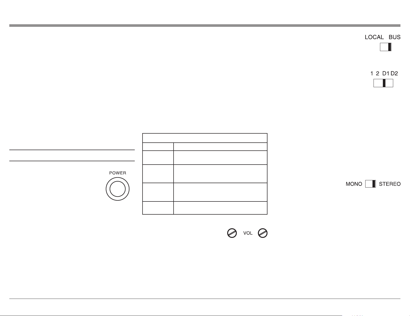
2. The LOCAL-BUS Switch deter-
mines if the Audio Signal will
originate from the Unbalanced
Left and Right Input Jacks or
from the BUS Analog/Digital Input Connectors.
3. When the LOCAL-BUS Switch
is placed in the BUS Position the
selection of the Audio Signal Input
for the Power Amplifier Channels
is determined by the 1-2-D1-D2 Selector Switch.
4. The 1 and 2 Selector Switch Positions are for the
Analog Signals from the BUS1/BUS2 Left and
Right Input Jacks for the Amplifier Channels.
5. The D1 Switch Position allows the Digital Audio
Signals from the DIG1 Optical or Coaxial Input
Connector to be available for the Power Amplifier
Channels. The D2 Switch Position performs the
same functions from the DIG2 Optical or Coaxial
Input Connector.
Mode Selector
Each pair of the Twelve
Power Amplifier Channels
have a Mode Switch located on the MI1250 Rear
Panel for STEREO or MONO Mode of Operation.
The Mode Switch affects all three of the Analog Input
Pairs. It also affects the Digital Optical or Coaxial
Input Audio Signal.
Auto Off Function
1. The MI1250 incorporates Power Save Circuitry to
automatically place the unit into the power saving
Standby Mode approximately 10 minutes after
there has been an absence of an audio input signal
on all twelve channels.
2. When there is a Power Control Connection
between the MI1250 and a Preamplifier or Source
Component, the AUTO OFF Function is bypassed.
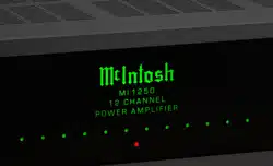
Channel Operational Indication
The MI1250 Front Panel has twelve LEDs. The LEDs
indicate the current functioning status for each of the
twelve channels.
MI1250 Channel Operation Functions
LED COLOR
Functional Status
LED not
Illuminated
Indicates when the Channel is OFF
Green
Indicates when the Channel is ON with an
Audio Signal Present and Normal Operation for
the Channel exists
Amber
Indicates when maximum Power Output for the
Channel has occured with prevention of Audio
Clipping
Red
Indicates current limit or short circuit for the
Channel Loudspeaker Output Connection
Volume Controls
Each of the Amplifier Channels
have volume control knobs. The
volume control knobs allow channel volume levels to
be adjusted individually.
Input Selector
1. Each pair of the Amplifier Channels have switches
on the Rear Panel for selection of the Input Source
Signal that determine the Audio Signal Mode.
Refer to pages 6 and 7 for additional information.
How to Operate
Power On
The LED STANDBY/ON Indicator
illuminates to indicate the unit is
connected to AC Power. To switch
ON the MI1250, press the POWER
Push-button on the Front Panel or switch
On the Audio Source Component provided there is a
Power Control Cable Connection to the MI1250.
1. It will take about 6 seconds for initialization of
the internal circuitry to take place on the MI1250
when switched On.
2. There must be a power control connection between
the MI1250 and the Audio Source Component in
order for the Remote Control Operation Power
ON/OFF to function.
3. When the MI1250 is receiving a Power Control
ON Signal, the Front Panel POWER Push-Button
becomes inactive.
Loudspeaker Socket. Then connect the opposite
end of the Loudspeaker Hookup Cable to the
Loudspeaker Connection Terminals. Make sure
to match up the MI1250 Negative and Positive
Output Connection on the Plug Connector, with
the Loudspeaker Negative and Positive Input
Connections.
WARNING: Loudspeaker terminals are hazardous
live and present a risk of electric shock.
For additional instruction on making
Loudspeaker Connections contact your
McIntosh Dealer or McIntosh Technical
Support.
9. After all the connections have been completed,
connect the MI1250 power cord to an active AC
outlet.
Loading ...
Loading ...
Loading ...