Loading ...
Loading ...
Loading ...
8
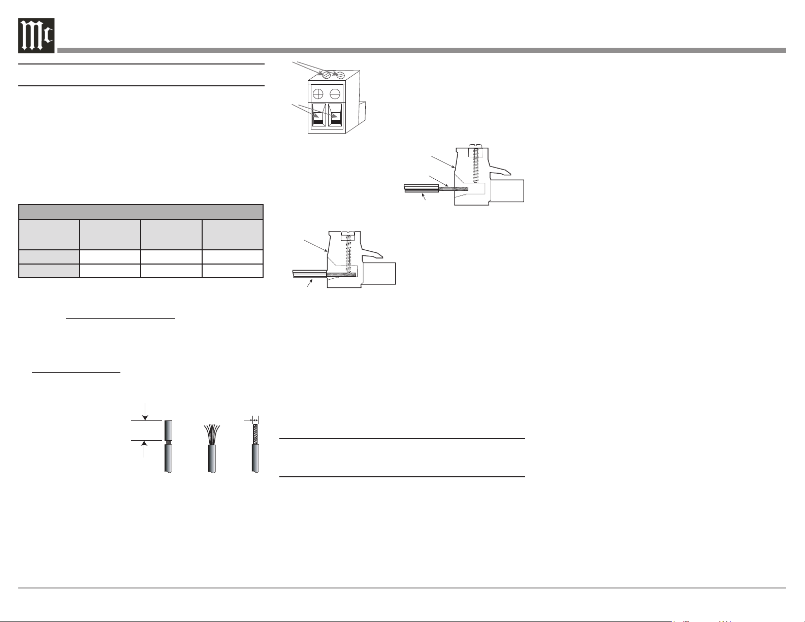
3. Adjust the two top screws of
the Loudspeaker Connection
Plug to provide a sufcient
opening size so the bare wire
will t into the connector.
4. Insert the
Loudspeaker Hookup
Cable bare wire end into
the Connection Plug
opening.
5. With the Hookup Cable
insulation ush with the
Loudspeaker Connection
Plug opening, rotate the
two top screws to secure
the Hookup Cable with
the plug.
6. Now complete the remaining Loudspeaker
Connection Plugs and the Loudspeaker Hookup Cables
WA R N I NG: The MI1250 Chassis Loudspeaker
Connection Socket Pins present a risk of
electric shock when the Amplifier is On. For
additional assistance on using Loudspeaker
Connections Plugs contact your McIntosh
Dealer or McIntosh Technical Support.
Output Plug Connection
When connecting the Loudspeaker Hookup Cables
to the MI1250 using the supplied Loudspeaker
Connection Plugs.
1. To minimize power losses in the hookup cables,
use cables with the largest wire thickness that will
physically t in your application: American Wire
Gauge (AWG) species cable wire thickness. A
smaller AWG number represents a larger wire thick-
ness. Reference the following table as a guideline.
Loudspeaker Cable Distance vs Wire Gauge Guide
Loudspeaker
Impedance
25 feet
(7.62 meters)
or less
50 feet
(15.24 meters)
or less
100 feet
(30.48 meters)
or less
4 Ohms
14AWG 12AWG 10AWG
8 Ohms
16AWG 14AWG 12AWG
This McIntosh Power Amplifier is designed for
Loudspeakers with an impedance of 4 ohms or 8 ohms.
Connect a single Loudspeaker only to each Channel
Output Terminal.
2. The Loudspeaker Hookup Cable for attachment to
the MI1250 Power Amplifier:
Bare wire cable ends: Carefully remove sufficient
insulation from the cable ends. If the cable is
stranded, carefully twist the strands together as
tightly as possible.
Note:
2a. If the Loudspeaker
Cable used is
greater in size than
12AWG, it can be
used by removing some of the copper strands after
the insulation is removed from the cable end. The
acceptable diameter of the copper stands size is
0.100 inches (2.54 mm) so it will fit the into opening
on the MI1250 Connection Plug.
2b. If desired, the twisted ends can be tinned with
solder to keep the strands together.
typical Multichannel System. Your system may vary
from this, however the actual components would be
connected in a similar manner. For additional infor-
mation refer to “Connector Information” on page 3.
1. For Remote Power Control, connect a power
control cable from the A/V Control Center Power
Control Trigger/Output 2 to the Amplifier POWER
CONTROL INPUT.
Note: When the Power Control Cable is connected
between the MI1250 and an A/V Control
Center, the AUTO OFF Signal Sensing
Circuitry is automatically disabled.
2. Optionally, connect the MI1250 POWER
CONTROL OUT using a power control cable to
the first Loudspeaker and then connect the first
Loudspeaker Power Control Out to the Power
Control In on the next Loudspeaker. Connect the
remaining Loudspeakers in the same way.
3. Connect unbalanced cables from the A/V Control
Center Analog Audio Out Zone 2 (Left and Right
Channel) to the MI1250 BUS 1 INPUTS, making
sure to match up channel designations.
4. Connect unbalanced cables from the A/V Control
Center Analog Audio Out Zone 3 (Left and Right
Channel) to the MI1250 BUS 2 INPUTS, making
sure to match up channel designations.
5. Place the CHANNEL 1/2, 3/4 and 5/6 Input
Selector Switches to the “1” Position.
6. Place the CHANNEL 7/8, 9/10 and 11/12 Input
Selector Switches to the “2” Position.
7. Place the Analog Audio/Digital Audio CHANNEL
all channel Input Selector Switches to the “BUS”
Position.
8. With the Loudspeaker Hookup Cable attached to
the Loudspeaker Connection Plug, insert the Plug
End into the correct MI1250 Rear Panel Chassis
How to Connect from a Multichannel
Zone Preamplier
WA R N ING: Do not connect the AC Power Cord to the
MI1250 Rear Panel until after the Loudspeaker
Connections are made. Failure to observe this
could result in Electric Shock.
The following connection instructions, together
with the Connection Diagram on page 7, depict a
0.100 inches
2.54 mm
0.5 inches
12.7 mm
Cable Insulation
Loudspeaker
Connection
Plug
Cable Insulation
Cable Bare Wire
Loudspeaker
Connection
Plug
Openings
Screws
Loading ...
Loading ...
Loading ...