Loading ...
Loading ...
Loading ...
_tLIJ_[¢]=l I='TO]IInlI;:I,41:Y,JI.']
The router accessory converts your cuttnngtool Into a
small hobby plunge router that uscapable of handling
small '/," shank router butsas well as the spiral cutting but
The tnltnngbase is ideal for bevel cutting The plunge
feature allows you to pre-set up to three ddferent cuttnng
depths
IA WARNINGI
Unplug the tool from the power source before
changing accessories, changing bits and making
adjustments.
Before turning the tool ON, check to make sure the bit
and all accessory fasteners are securely tightened.
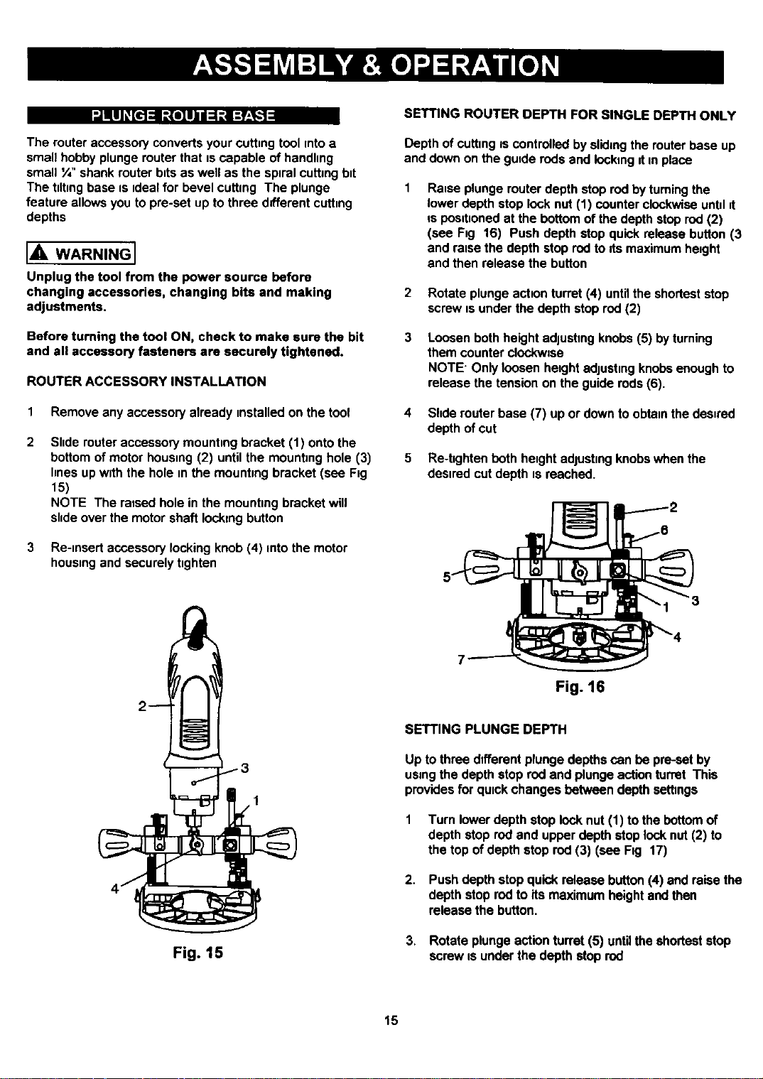
ROUTER ACCESSORY INSTALLATION
1 Remove any accessory already unstalled on the tool
Slide router accessory mounting bracket (1) onto the
bottom of motor housnng(2) until the mounting hole (3)
hnes up wuththe hole nnthe mountung bracket (see Fig
15)
NOTE The raised hole in the mounting bracket will
shde over the motor shaft locking button
3 Re-nnsert accessory locking knob (4) into the motor
housnngand securely tighten
1
Fig. 15
SETTING ROUTER DEPTH FOR SINGLE DEPTH ONLY
Depth of cutting os controlled bysliding the router base up
and down on the gutde rods and locking dun place
Rause plunge router depth stop rod by turning the
lower depth stop lock nut (1) counter clockwise untul=t
is posutnonedat the bottom of the depth stop rod (2)
(see Fig 16) Push depth stop quick release button (3
and reuse the depth stop rod to Its maximum height
and then release the button
2 Rotate plunge actuonturret (4) untilthe shortest stop
screw usunder the depth stop rod (2)
3
Loosen both height adjushng knobs (5) byturning
them counter clockwtse
NOTE" Only loosen height edjustmg knobs enough to
release the tension on the guide rods (6).
4 Shde muter base (7) up or down to obtannthe desured
depth of cut
5 Re-hghtenbothheughtadjustnngknobswhenthe
desiredcutdepthtsreached.
Fig. 16
SETTING PLUNGE DEPTH
Up to three different plunge depths can be preset by
using the depth stop rod and plunge action turret This
provides for qutck changes between depth setbngs
Turn lowerdepthstop locknut (1) to thebottomof
depthstop rodand upperdepthstoplocknut(2) to
the top of depthstoprod(3) (see Fig 17)
2. Pushdepthstopquickreleasebutton(4) and raisethe
depthstoprodto itsmaximumheightandthen
releasethe button.
3. Rotate plungeactionturret(5) untiltheshorteststop
screwisunderthe depthstoprod
15
Loading ...
Loading ...
Loading ...