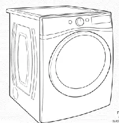
DRYER MAINTENANCE AND CARE
Cleaning the Dryer Location
Keep dryer area clear and free from items that would block the airflow for proper dryer operation. This includes clearing piles of laundry in front of the dryer.
Cleaning the Dryer Interior
To clean dryer drum:
1. Use nonflammable cleaner or a mild hand dish detergent mixed at a low concentration with very warm water, and rub with a soft cloth.
- Rinse well with a wet sponge or towel.
- Tumble a load of clean clothes or towels to dry drum. OR
2. Use a microfiber cloth and very warm water in a spray bottle to clean the drum and a second microfiber towel to dry.
NOTE: Garments that contain unstable dyes, such as denim blue jeans or brightly colored cotton items, may discolor the rear of the dryer interior. These stains are not harmful to your dryer and will not stain future loads of clothes. Dry unstable dye items inside out to avoid transfer of dye
Removing Accumulated Lint
From inside the dryer cabinet: Lint should be removed every 2 years, or more often, depending on dryer usage. Cleaning should be done by a qualified appliance service or ventilation system cleaner.
From the exhaust vent: Lint should be removed every 2 years, or more often, depending on dryer usage
Cleaning the Lint Screen
Every load cleaning: The lint screen may be located either in the door opening or the top of the dryer depending on model. A screen blocked by lint can increase drying time.
To clean:
1. Remove the lint screen. If necessary, press the tab to release and open the lint screen. Roll lint off the screen with your fingers. Do not rinse or wash screen to remove lint. Wet lint is hard to remove
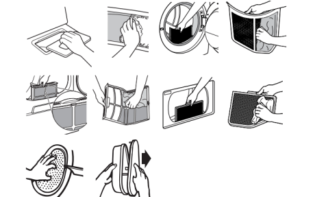
2. Push the lint screen firmly back into place
IMPORTANT:
- Do not run the dryer with the lint screen loose, damaged, blocked, or missing. Doing so can cause overheating and damage to both the dryer and fabrics.
- If lint falls off the screen into the dryer during removal, check the exhaust hood and remove the lint. See “Venting Requirements” in the Installation Instructions.
- Clean space where lint screen is located, as needed. Using a vacuum, gently remove any lint that has accumulated outside of the lint screen.
As-needed cleaning:
Laundry detergent and fabric softener residue can build up on the lint screen. This buildup can cause longer drying times for your clothes, or cause the dryer to stop before your load is completely dry. The screen is probably clogged if lint falls off while the screen is in the dryer. Clean the lint screen with a nylon brush every 6 months, or more frequently, if it becomes clogged due to a residue buildup.
To wash:
1. Roll lint off the screen with your fingers.
2. Wet both sides of lint screen with hot water.
3. Wet a nylon brush with hot water and liquid detergent. Scrub lint screen with the brush to remove residue buildup.
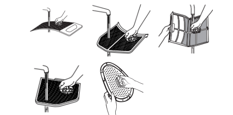
4. Rinse screen with hot water.
5. Thoroughly dry lint screen with a clean towel. Reinstall screen in dryer.
Changing the Drum Light (on some models)
1. Unplug dryer or disconnect power.
2. Open the dryer door. Locate the light bulb cover on the back wall of the dryer. Using a 1/4" (6.5 mm) nut driver or socket wrench, remove the screw located in the lower right-hand corner of the cover. Remove the cover.
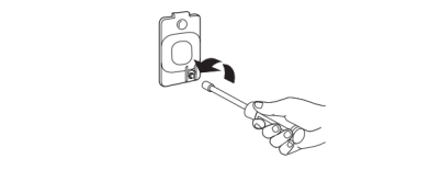
3. Turn bulb counterclockwise. Replace the bulb with a 10 W appliance bulb only. Replace the cover and secure with the screw.
4. Plug in dryer or reconnect power
Check Your Vent System for Good Airflow
Good Airflow
Along with heat, dryers require good airflow to efficiently dry laundry. Proper venting will reduce your drying times and improve your energy savings. See Installation Instructions. The venting system attached to the dryer plays a big role in good airflow. Blocked or crushed vents as well as improper venting installation will reduce air flow and dryer performance. Service calls caused by improper venting are not covered by the warranty and will be paid by the customer, regardless of who installed the dryer. To clean or repair venting, contact a venting specialist.
Maintain Good Airflow
- Cleaning your lint screen before each load.
- Replace plastic or foil vent material with 4" (102 mm) diameter heavy, rigid vent material.
- Use the shortest length of vent possible.
- Use no more than four 90° elbows in a vent system; each bend and curve reduces airflow

- Remove lint and debris from the exhaust hood.
- Remove lint from the entire length of the vent system at least every 2 years. When cleaning is complete, be sure to follow the Installation Instructions for final product check.
- Clear away items from the front of the dryer.
Nonuse, Storage, and Moving Care
Nonuse or Storage Care If you will be on vacation or not using your dryer for an extended period of time, you should:
1. Unplug dryer or disconnect power.
2. Clean lint screen. See “Cleaning the Lint Screen.”
3. Steam Models Only: Turn off the water supply to the dryer. This helps to avoid flooding (due to a water pressure surge) while you are away.
Moving Care
For power supply cord-connected dryers:
1. Unplug the power supply cord.
2. Steam models only: Shut off water faucet. Disconnect the water inlet hose from faucet; then drain the hose. Transport hose separately.
3. Make sure leveling legs are secure in dryer base.
4. Use tape to secure dryer door. 5. On models with base trim, remove base trim before moving dryer. See “Install and remove base trim (on some models)” for details.
To winterize the dryer:
1. Unplug dryer or disconnect power.
2. Shut off water faucet.
3. Disconnect water inlet hose from faucet and drain.
To use the dryer again:
1. Flush water pipes. Reconnect water inlet hose to faucet. Turn on water faucet.
2. Plug in dryer or reconnect power as described in the Installation Instructions.
Reinstalling the Dryer
- Follow the Installation Instructions to locate, level, and connect the dryer
Special Instructions for Steam Models
- Install and store your dryer where it will not freeze. Because some water may stay in the hose, freezing can damage your dryer. If storing or moving your dryer during freezing weather, winterize it
Water inlet hose
- Replace inlet hose and hose screen after 5 years of use to reduce the risk of hose failure. Periodically inspect and replace inlet hose if bulges, kinks, cuts, wear, or leaks are found. When replacing your inlet hose, record the date of replacement
INSTALLATION REQUIREMENTS
Tools and Parts
Gather the required tools and parts before starting installation.
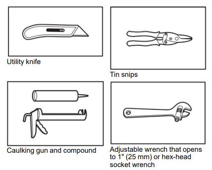
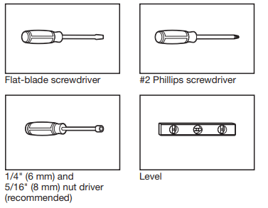
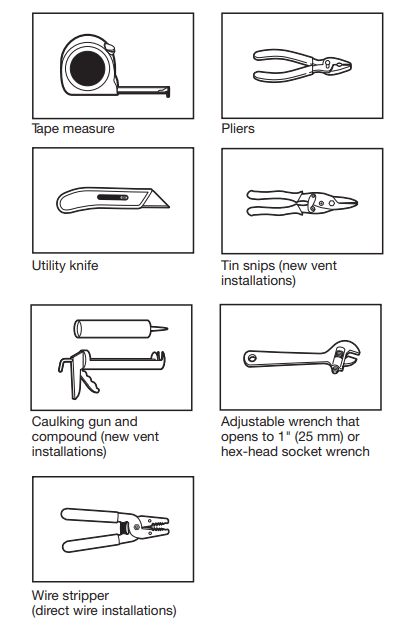
Tools needed for all installations:
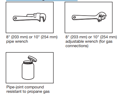
Tools needed for gas installations:
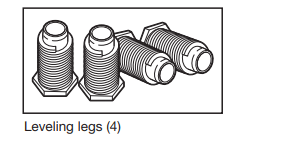
Parts supplied (all models):
Parts needed (steam models):
Parts package is located in dryer drum. Check that all parts are included.
NOTE: Do not use leveling legs supplied with dryer if installing with a pedestal or a stack kit.
Parts needed (not supplied with dryer):
- Vent clamps
- Vent elbows and vent work
Additional parts may be required, depending on your installation. Check local codes. Check existing electrical supply and venting. Read “Electrical Requirements” and “Venting Requirements” before purchasing parts
If using a power supply cord:
Use a UL Listed power supply cord kit marked for use with clothes dryers. The kit should contain:
- A UL Listed 30 A power supply cord, rated 120/240 V minimum. The cord should be type SRD or SRDT and be at least 4 ft. (1.22 m) long. The wires that connect to the dryer must end in ring terminals or spade terminals with upturned ends.
- A UL Listed strain relief.
Optional Equipment (not supplied with dryer):
Refer to your Use and Care Guide for information about accessories available for your dryer
LOCATION REQUIREMENTS
You will need:
- A location allowing for proper exhaust installation. See “Venting Requirements.”
- A separate 15 or 20 A circuit for a gas dryer or 30 A circuit for an electric dryer.
- If using power supply cord, a grounded electrical outlet located within 2 ft. (610 mm) of either side of dryer. See “Electrical Requirements.”
- Floor must support dryer weight of 200 lbs. (90.7 kg). Also consider weight of companion appliance.
- Cold water faucets located within 4 ft. (1.2 m) of the water fill valves, and water pressure of 20–120 psi (138–827 kPa). You may use your washer’s water supply by purchasing the necessary parts noted in “Parts needed.”
- Level floor with maximum slope of 1" (25 mm) under entire dryer. If slope is greater than 1" (25 mm), install Extended Dryer Feet Kit, Part Number 279810. If not level, clothes may not tumble properly and automatic sensor cycles may not operate correctly.
- For garage installation, place dryer at least 18" (460 mm) above floor. If using a pedestal, you will need 18" (460 mm) to bottom of dryer.
- The dryer must not be installed or stored in an area where it will be exposed to water and/or weather.
IMPORTANT: Do not operate, install, or store dryer where it will be exposed to water, weather, or at temperatures below 40°F (4°C). Lower temperatures may cause dryer not to shut off at end of automatic sensor cycles, resulting in longer drying times.
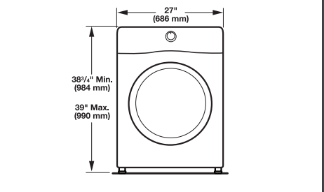
DRYER DIMENSIONS
Front view:
Side view:Whirlpool®, Amana, and Inglis Models
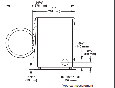
Maytag® Models
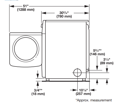
Back view:
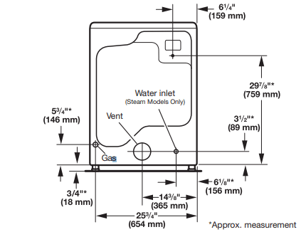
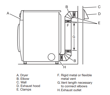
NOTE: Most installations require a minimum of 5" (127 mm) clearance behind dryer for exhaust vent with elbow. See “Venting Requirements.”
Installation Clearances
For each arrangement, consider allowing more space for ease of installation and servicing, spacing for companion appliances, and clearances for walls, doors, and floor moldings. Space must be large enough to allow door to fully open. Add spacing on all sides of dryer to reduce noise transfer. If a closet door or louvered door is installed, top and bottom air openings in door are required.
Check code requirements. Some codes limit, or do not permit, installation of the dryer in garages, closets, mobile homes, or sleeping quarters. Contact your local building inspector.
NOTE: No other fuel-burning appliance can be installed in the same closet as a dryer.
Installation spacing for recessed area or closet installation
All dimensions show recommended and minimum spacing allowed.
- Additional spacing should be considered for ease of installation and servicing.
- Additional clearances might be required for wall, door, floor moldings, dryer venting, and gas line.
- Additional spacing should be considered on all sides of the dryer to reduce noise transfer.
- For closet installation with a door, minimum ventilation openings in the top and bottom of the door are required. Louvered doors with equivalent ventilation openings are acceptable.
- Companion appliance spacing should also be considered.
Recommended installation clearances (dryer only):
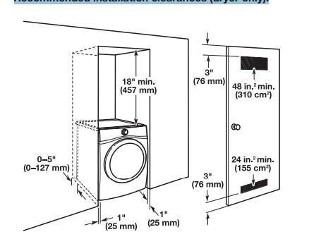
0" (0 mm) rear spacing is allowed for straight back venting only. For steam models only, inlet hose must not be kinked.
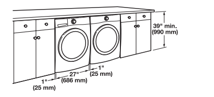
Custom under-counter installation:
Mobile home – Additional installation requirements:
This dryer is suitable for mobile home installations. The installation must conform to the Manufactured Home Construction and Safety Standard, Title 24 CFR, Part 3280 (formerly the Federal Standard for Mobile home construction and Safety, Title 24, HUD Part 280) or Standard CAN/CSA-Z240 MH
Mobile home installations require:
- Metal exhaust system hardware, available for purchase from your dealer. For further information, see “Assistance or Service” in your Use and Care Guide.
- Special provisions must be made in mobile homes to introduce outside air into dryer. Openings (such as a nearby window) should be at least twice as large as dryer exhaust opening.
For mobile home installation of gas dryers:
- Mobile Home Installation Hold-down Kit Part Number 346764 is available to order. For further information, see “Assistance or Service” in your Use and Care Guide.
ELECTRICAL REQUIREMENTS – U.S.A. ONLY
It is your responsibility:
■ To contact a qualified electrical installer.
■ To be sure that the electrical connection is adequate and in conformance with the National Electrical Code, ANSI/NFPA 70 – latest edition and all local codes and ordinances.
- The National Electrical Code requires a 4-wire power supply connection for homes built after 1996, dryer circuits involved in remodeling after 1996, and all mobile home installations.
- A copy of the above code standards can be obtained from: National Fire Protection Association, One Batterymarch Park, Quincy, MA 02269.
■ To supply the required 3 or 4 wire, single-phase, 120/240 V, 60 Hz, AC-only electrical supply (or 3 or 4 wire, 120/208 V electrical supply, if specified on the serial/rating plate) on a separate 30 A circuit, fused on both sides of the line. Connect to an individual branch circuit. Do not have a fuse in the neutral or grounding circuit.
■ Do not use an extension cord.
■ If codes permit and a separate ground wire is used, it is recommended that a qualified electrician determine that the ground path is adequate.
Electrical Connection
To properly install your dryer, you must determine the type of electrical connection you will be using and follow the instructions provided for it here.
- This dryer is manufactured ready to install with a 3-wire electrical supply connection. The neutral ground conductor is permanently connected to the neutral conductor (white wire) within the dryer. If the dryer is installed with a 4-wire electrical supply connection, the neutral ground conductor must be removed from the external ground connector (green screw), and secured under the neutral terminal (center or white wire) of the terminal block. When the neutral ground conductor is secured under the neutral terminal (center or white wire) of the terminal block, the dryer cabinet is isolated from the neutral conductor. The green ground wire of the 4-wire power cord must be secured to the dryer cabinet with the green ground screw.
- If local codes do not permit the connection of a neutral ground wire to the neutral wire, see “Optional External Ground for 3-Wire Connection” in the “Power Supply Cord Connection” section.
- A 4-wire power supply connection must be used when the appliance is installed in a location where grounding through the neutral conductor is prohibited. Grounding through the neutral is prohibited for (1) new branch-circuit installations after 1996, (2) mobile homes, (3) recreational vehicles, and (4) areas where local codes prohibit grounding through the neutral conductors.
If using a power supply cord:
Use a UL Listed power supply cord kit marked for use with clothes dryers. The kit should contain:
- A UL Listed 30 A power supply cord, rated 120/240 V minimum. The cord should be type SRD or SRDT and be at least 4 ft. (1.22 m) long. The wires that connect to the dryer must end in ring terminals or spade terminals with upturned ends.
- A UL Listed strain relief.
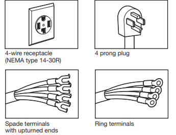
If your outlet looks like this
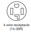 Then choose a 4-wire power supply cord with ring or spade terminals and UL Listed strain relief. The 4-wire power supply cord, at least 4 ft. (1.22 m) long, must have four 10-gauge copper wires and match a 4-wire receptacle of NEMA Type 14-30R. The ground wire (ground conductor) may be either green or bare. The neutral conductor must be identified by a white cover
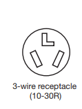 Then choose a 3-wire power supply cord with ring or spade terminals and UL listed strain relief. The 3-wire power supply cord, at least 4 ft. (1.22 m) long, must have three 10-gauge copper wires and match a 3-wire receptacle of NEMA Type 10-30R.
If connecting by direct wire:
Power supply cable must match power supply (4-wire or 3-wire) and be:
■ Flexible armored cable or nonmetallic sheathed copper cable (with ground wire), covered with flexible metallic conduit. All current-carrying wires must be insulated.
■ 10-gauge solid copper wire (do not use aluminum) at least 5 ft. (1.52 m) long.
ELECTRIC DRYER POWER HOOKUP – CANADA ONLY
It is your responsibility:
■ To contact a qualified electrical installer.
■ To be sure that the electrical connection is adequate and in conformance with Canadian Electrical Code, C22.1 – latest edition and all local codes. A copy of above codes standard may be obtained from: Canadian Standards Association, 178 Rexdale Blvd., Toronto, ON M9W 1R3 CANADA.
■ To supply the required 4-wire, single-phase, 120/240 V, 60 Hz, AC-only electrical supply on a separate 30 A circuit, fused on both sides of the line. A time-delay fuse or circuit breaker is recommended. Connect to an individual branch circuit.
■ This dryer is equipped with a UL Listed and/ or CSA International Certified Power Cord intended to be plugged into a standard 14-30R wall receptacle. The cord is 5 ft. (1.52 m) long. Be sure wall receptacle is within reach of dryer’s final location.
If using a replacement power supply cord, it is recommended that you use Power Supply Cord Replacement Part Number 8529008. For further information, please reference service numbers located in the “Assistance or Service” section of your Use and Care Guide.
GROUNDING INSTRUCTIONS
For a grounded, cord-connected dryer: This dryer must be grounded. In the event of malfunction or breakdown, grounding will reduce the risk of electric shock by providing a path of least resistance for electric current. This dryer is equipped with a cord having an equipmentgrounding conductor and a grounding plug. The plug must be plugged into an appropriate outlet that is properly installed and grounded in accordance with all local codes and ordinances
WARNING:
Improper connection of the equipmentgrounding conductor can result in a risk of electric shock. grounding conductor can result in a risk of electric shock. epresentative or personnel if you are in doubt as to whether the dryer is properly grounded. Do not modify the plug provided with oper outlet
GAS DRYER POWER HOOKUP
ELECTRICAL REQUIREMENTS
■ 120 V, 60 Hz, AC-only, 15 or 20 A fused electrical supply is required. A time-delay fuse or circuit breaker is recommended. It is also recommended that a separate circuit serving only this dryer be provided
GROUNDING INSTRUCTIONS SAVE THESE INSTRUCTIONS
For a grounded, cord-connected dryer: This dryer must be grounded. In the event of malfunction or breakdown, grounding will reduce the risk of electric shock by providing a path of least resistance for electric current. This dryer is equipped with a cord having an equipmentgrounding conductor and a grounding plug. The plug must be plugged into an appropriate outlet that is properly installed and grounded in accordance with all local codes and ordinances.
WARNING: Improper connection of the equipmentgrounding conductor can result in a risk of electric shock. epresentative or personnel if you are in doubt as to whether the dryer is properly grounded. Do not modify the plug provided
GAS SUPPLY REQUIREMENTS
GAS TYPE
Natural Gas:
This dryer is equipped for use with natural gas. It is certified by UL for use with propane gas with appropriate conversion.
- Your dryer must have the correct burner for the type of gas in your home. Burner information is located on the rating plate in the door well of your dryer. If this information does not agree with the type of gas available, contact your dealer or call the phone numbers referenced in the “Assistance or Service” section of your Use and Care Guide.
Propane Gas Conversion:
IMPORTANT: Conversion must be made by a qualified technician.
No attempt shall be made to convert the appliance from the gas specified on the model/serial rating plate for use with a different gas without consulting your gas company.
GAS SUPPLY LINE
Option 1 (Recommended Method)
Flexible stainless steel gas connector:
- If local codes permit, use a new flexible stainless steel gas connector (Design Certified by the American Gas Association or CSA International) to connect your dryer to the rigid gas supply line. Use an elbow and a 3/8" flare x 3/8" NPT adapter fitting between the stainless steel gas connector and the dryer gas pipe, as needed, to prevent kinking.
Option 2 (Alternate Method)
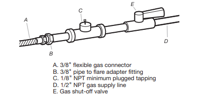
Approved aluminum or copper tubing:
- Must include 1/8" NPT minimum plugged tapping accessible for test gauge connection, immediately upstream of the gas connection to the dryer. See illustration below.
- 1/2" IPS pipe is recommended.
- 3/8" approved aluminum or copper tubing is acceptable for lengths under 20 ft. (6.1 m) if local codes and gas supplier permit.
- If you are using natural gas, do not use copper tubing.
- Lengths over 20 ft. (6.1 m) should use larger tubing and a different size adapter fitting.
- If your dryer has been converted to use propane gas, 3/8" propane compatible copper tubing can be used. If the total length of the supply line is more than 20 ft. (6.1 m), use larger pipe.
NOTE: Pipe-joint compounds that resist the action of propane gas must be used. Do not use TEFLON®† tape.
- Must include shut-off valve.
In the U.S.A.: An individual manual shut-off valve must be installed within six (6) ft. (1.8 m) of the dryer in accordance with the National Fuel Gas Code, ANSI Z223.1. The location should be easy to reach for opening and closing
In Canada: An individual manual shut-off valve must be installed in accordance with the B149.1, Natural Gas and Propane Installation Code. It is recommended that an individual manual shut-off valve be installed within six (6) ft. (1.8 m) of the dryer. The location should be easy to reach for opening and closing.
GAS SUPPLY CONNECTION REQUIREMENTS INSTALL LEVELING LEGS
- Use an elbow and a 3/8" flare x 3/8" NPT adapter fitting between the flexible gas connector and the dryer gas pipe, as needed to avoid kinking.
- Use only pipe-joint compound. Do not use TEFLON® tape.
- This dryer must be connected to the gas supply line with a listed flexible gas connector that complies with the standard for connectors for gas appliances, ANSI Z21.24 or CSA 6.10.
BURNER INPUT REQUIREMENTS
Elevations above 2,000 ft. (610 m):
- When installed above 2,000 ft. (610 m) a 4% reduction of the burner Btu rating shown on the model/serial number plate is required for each 1,000 ft. (305 m) increase in elevation.
Gas supply pressure testing
- The dryer must be disconnected from the gas supply piping system during pressure testing at pressures greater than 1/2 psi.
DRYER GAS PIPE
- The gas pipe that comes out through the rear of your dryer has a 3/8" male pipe thread
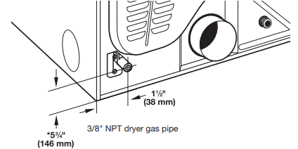
* NOTE: If the dryer is mounted on a pedestal, the gas pipe height must be an additional 10" (254 mm) or 15.5" (394 mm) from the floor, depending on the pedestal model. For a garage installation, the gas pipe height must be an additional 18" (460 mm) from the floor.
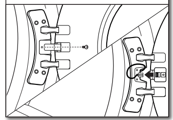
INSTALL LEVELING LEGS
1. Prepare dryer for leveling legs
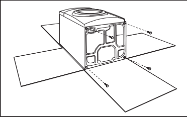
To avoid damaging floor, use a large flat piece of cardboard from dryer carton; place under entire back edge of dryer. Firmly grasp dryer body (not console panel) and gently lay dryer down on cardboard.
2. Screw in leveling legs
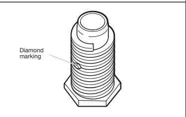
Examine leveling legs and locate the diamond marking. Screw legs into leg holes by hand – use a wrench to finish turning legs until diamond marking is no longer visible.
Place a carton corner post from dryer packaging under each of the two dryer back corners. Stand the dryer up. Slide the dryer on the corner posts until it is close to its final location. Leave enough room to connect the exhaust vent.
ELECTRICAL CONNECTION
1. Choose electrical connection type
 Power supply cord 4-wire receptacle (NEMA Type 14-30R). Go to “Power Supply Cord Connection.”
 Power supply cord 3-wire receptacle (NEMA Type 10-30R). Go to “Power Supply Cord Connection.”
 4-wire direct connection: Go to “Direct Wire Connection.”
 3-wire direct connection: Go to “Direct Wire Connection.”
NOTE: If local codes do not permit connection of a cabinet-ground conductor to neutral wire, go to “Optional External Ground for 3-Wire Connection.” This connection may be used with either a power supply cord or a direct wire connection.
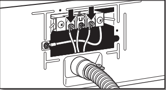
2. Remove terminal block cover
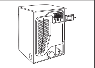
Remove hold-down screw and terminal block cover.
Power Supply Cord Connection
Power supply cord strain relief
1. Attach power supply cord strain relief
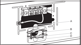
Remove the screws from a 3/4" (19 mm) UL Listed strain relief. Put the tabs of the two clamp sections (C) into the hole below the terminal block opening (B) so that one tab is pointing up (A) and the other is pointing down (D), and hold in place. Tighten strain relief screws just enough to hold the two clamp sections (C) together.
2. Attach power supply cord to strain relief
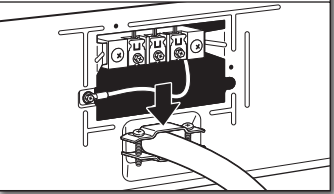
Put power supply cord through the strain relief. Be sure that the wire insulation on the power supply cord is inside the strain relief. The strain relief should have a tight fit with the dryer cabinet and be in a horizontal position. Do not further tighten strain relief screws at this point.
If your outlet looks like this:
 Power supply cord 4-wire receptacle (NEMA Type 14-30R): Go to “4-Wire Power Supply Cord Connection” on this page.
Power supply cord 3-wire receptacle (NEMA Type 10-30R): Go to “3-Wire Power Supply Cord Connection” on page 13.
4-Wire Power Supply Cord Connection
IMPORTANT: A 4-wire connection is required for mobile homes and where local codes do not permit the use of 3-wire connections.
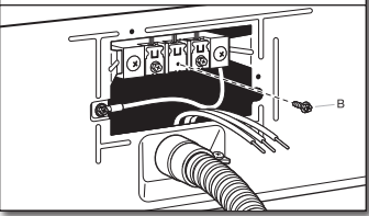
1. Prepare to connect neutral ground wire and neutral wire
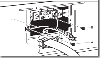
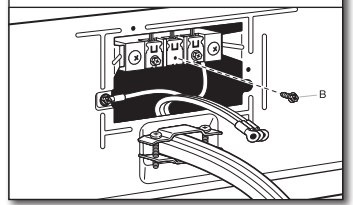
Remove center terminal block screw (B). Remove neutral ground wire (E) from green external ground conductor screw (A).
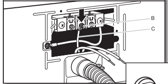
2. Connect neutral ground wire and neutral wire
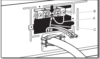
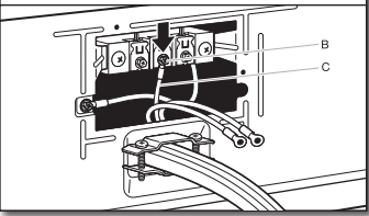
Connect neutral ground wire (E) and neutral wire (white or center) (C) of power supply cord under center terminal block screw (B). Tighten screw.
3. Connect ground wire
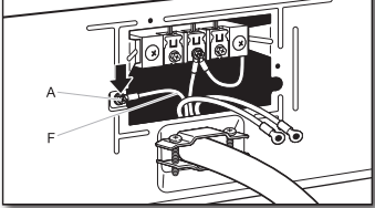
Connect ground wire (F) (green or bare) of power supply cord under green external ground conductor screw (A). Tighten screw.
4. Connect remaining wires
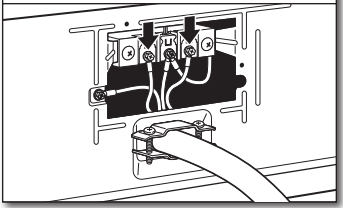
Connect remaining wires under outer terminal block screws. Tighten screws. Finally, reinsert tab of terminal block cover into slot of dryer rear panel. Secure cover with hold-down screw. Now go to “Venting Requirements.”
3-Wire Power Supply Cord Connection
Use where local codes permit connecting cabinet-ground conductor to neutral wire.
1. Remove center screw
2. Connect neutral wire
Connect neutral wire (white or center) (C) of power supply cord under center terminal block screw (B). Tighten screw.
3. Connect remaining wires
Connect remaining wires under outer terminal block screws. Tighten screws. Finally, reinsert tab of terminal block cover into slot of dryer rear panel. Secure cover with hold-down screw. Now go to “Venting Requirements.”
Direct Wire Connection
Direct wire strain relief
1. Attach direct wire strain relief
Unscrew the removable conduit connector (A) and any screws from a 3/4" (19 mm) UL Listed strain relief. Put the threaded section of the strain relief (C) through the hole below the terminal block opening (B). Reaching inside the terminal block opening, screw the removable conduit connector (A) onto the strain relief threads and tighten securely
2. Attach direct wire cable to strain relief
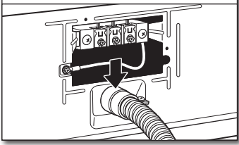
Put direct wire cable through the strain relief. The strain relief should have a tight fit with the dryer cabinet and be in a horizontal position. Tighten strain relief screw against the direct wire cable.
If your wiring looks like this:
4-wire direct connection: Go to “Direct Wire Connection.”
3-wire direct connection: Go to “Direct Wire Connection.”
4-Wire Direct Wire Connection
IMPORTANT: A 4-wire connection is required for mobile homes and where local codes do not permit 3-wire connections.
1. Prepare your 4-wire cable for direct connection
Direct wire cable must have 5 ft. (1.52 m) of extra length so dryer may be moved if needed.
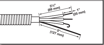
Strip 5" (127 mm) of outer covering from end of cable, leaving bare ground wire at 5" (127 mm). Cut 11 /2" (38 mm) from remaining three wires. Strip insulation back 1" (25 mm). Shape ends of wires into hooks.
2. Prepare to connect neutral ground wire and neutral wire
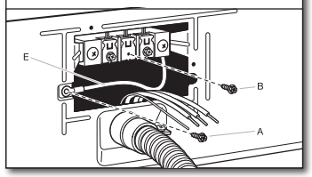
Remove center terminal block screw (B). Remove neutral ground wire (E) from green external ground conductor screw (A).
3. Connect neutral ground wire and neutral wire
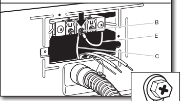
Connect neutral ground wire (E) and place hooked end (hook facing right) of neutral wire (white or center wire) (C) of direct wire cable under center screw of terminal block (B). Squeeze hooked ends together and tighten screw.
4. Connect ground wire
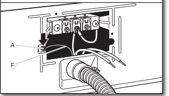
Connect ground wire (green or bare) (F) of direct wire cable under green external ground conductor screw (A). Tighten screw.
5. Connect remaining wires
Place hooked ends of remaining direct wire cable wires under outer terminal block screws (hooks facing right). Squeeze hooked ends together and tighten screws. Finally, reinsert tab of terminal block cover into slot of dryer rear panel. Secure cover with hold-down screw. Now go to “Venting Requirements.”
3-Wire Direct Wire Connection
Use where local codes permit connecting cabinet-ground conductor to neutral wire.
1. Prepare your 3-wire cable for direct connection
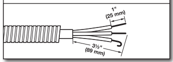
Direct wire cable must have 5 ft. (1.52 m) of extra length so dryer may be moved if needed.
Strip 31 /2" (89 mm) of outer covering from end of cable. Strip insulation back 1" (25 mm). If using 3-wire cable with ground wire, cut bare wire even with outer covering. Shape wire ends into hooks.
2. Remove center screw
Remove center terminal block screw (B).
3. Connect neutral wire
Place hooked end of neutral wire (white or center) (C) of direct wire cable under center terminal block screw (B), hook facing right. Squeeze hooked end together. Tighten screw.
4. Connect remaining wires
Place hooked ends of remaining direct wire cable wires under outer terminal block screws (hooks facing right). Squeeze hooked ends together and tighten screws. Finally, reinsert tab of terminal block cover into slot of dryer rear panel. Secure cover with hold-down screw. Now go to “Venting Requirements.”
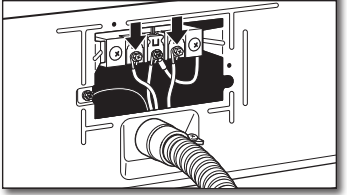
MAKE GAS CONNECTION
1. Connect gas supply to dryer
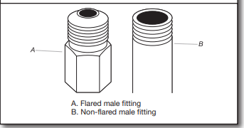
Remove red cap from gas pipe. Using a wrench to tighten, connect gas supply to dryer. Use pipe-joint compound on threads of all non-flared male fittings. If flexible metal tubing is used, be sure there are no kinks.
NOTE: For propane gas connections, you must use pipe-joint compound resistant to action of propane gas. Do not use TEFLON® tape
2. Plan pipe fitting connection (Option 1)
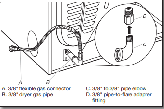
A combination of pipe fittings must be used to connect dryer to existing gas line. A recommended connection is shown. Your connection may be different, according to supply line type, size, and location.
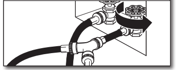
3. Open shut-off valve
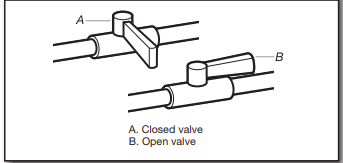
Open shut-off valve in supply line; valve is open when handle is parallel to gas pipe. Then, test all connections by brushing on an approved noncorrosive leak-detection solution. Bubbles will show a leak. Correct any leak found.
VENTING
Venting Requirements
WARNING: To reduce the risk of fire, this dryer MUST BE EXHAUSTED OUTDOORS.
IMPORTANT: Observe all governing codes and ordinances. Dryer exhaust must not be connected into any gas vent, chimney, wall, ceiling, attic, crawlspace, or a concealed space of a building. Only rigid or flexible metal vent shall be used for exhausting.
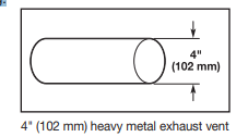
- Only a 4" (102 mm) heavy metal exhaust vent and clamps may be used.
- Do not use plastic or metal foil vent.
Rigid metal vent:
- Recommended for best drying performance and to avoid crushing and kinking.
Flexible metal vent: (Acceptable only if accessible to clean)
- Must be fully extended and supported in final dryer location.
- Remove excess to avoid sagging and kinking that may result in reduced airflow and poor performance.
- Do not install in enclosed walls, ceilings, or floors.
- The total length should not exceed 7¾ ft. (2.4 m).
- The length of flexible metal vent used must be included in the overall vent system design as shown in the “Vent System Charts.”
NOTE: If using an existing vent system, clean lint from entire length of the system and make sure exhaust hood is not plugged with lint. Replace plastic or metal foil vents with rigid metal or flexible metal vents. Review “Vent System Charts” and, if necessary, modify existing vent system to achieve best drying performance.
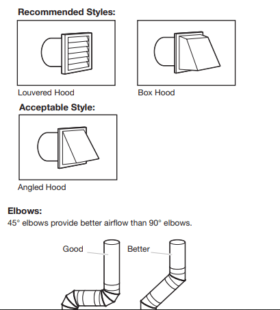
Exhaust hoods:
- An exhaust hood should cap the vent to keep rodents and insects from entering the home.
- Must be at least 12" (305 mm) from ground or any object that may obstruct exhaust (such as flowers, rocks, bushes, or snow).
- Do not use an exhaust hood with a magnetic latch.
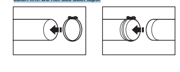
Clamps:
- Use clamps to seal all joints.
- Exhaust vent must not be connected or secured with screws or other fastening devices that extend into interior of duct and catch lint. Do not use duct tape.
Plan Vent System
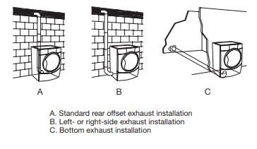
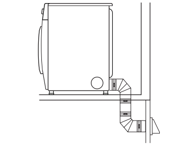
Recommended exhaust installation:
Optional exhaust installations:
- This dryer can be converted to exhaust out the right side, left side (all models except long vent), or through the bottom. If you prefer, you may contact your local dealer to have the dryer converted.
Special provisions for mobile homes:
Exhaust vent must be securely fastened to a noncombustible portion of mobile home and must not terminate beneath the mobile home. Terminate exhaust vent outside.
Determine vent path:
- Select route that will provide straightest and most direct path outdoors.
- Plan installation to use fewest number of elbows and turns.
- When using elbows or making turns, allow as much room as possible.
- Bend vent gradually to avoid kinking.
- Use as few 90° turns as possible.
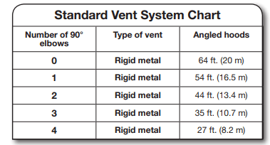
Determine vent length and elbows needed for best drying performance:
- Use the following “Vent System Charts” to determine type of vent material and hood combinations acceptable to use.
NOTE: Do not use vent runs longer than those specified in “Vent System Charts.” Exhaust systems longer than those specified will:
- Shorten life of dryer.
- Reduce performance, resulting in longer drying times and increased energy usage.
The “Vent System Charts” provide venting requirements that will help achieve best drying performance.
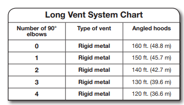
To determine if your model has a long vent system, refer to the type code located on the serial number plate in the inner door well. Example: An electric model would be DJAV – ELE – XXXXXXX-XXX. A gas model would be DJAV – NAT – XXXXXXXXXX.
NOTE: For long vent systems, use of box/louvered hoods will improve venting regardless of length.
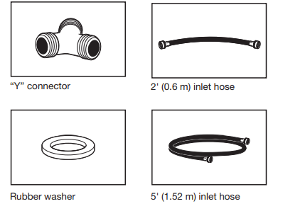
CONNECT INLET HOSE (STEAM MODEL ONLY)
For non-steam models, skip to “Connect Vent.” The dryer must be connected to the cold water faucet using the new inlet hoses (not supplied). Do not use old hoses.
NOTE: Replace inlet hoses after 5 years of use to reduce the risk of hose failure. Record hose installation or replacement dates on the hoses for future reference. Periodically inspect and replace hoses if bulges, kinks, cuts, wear, or leaks are found.
1. Turn cold water off, remove hose, and replace rubber washer
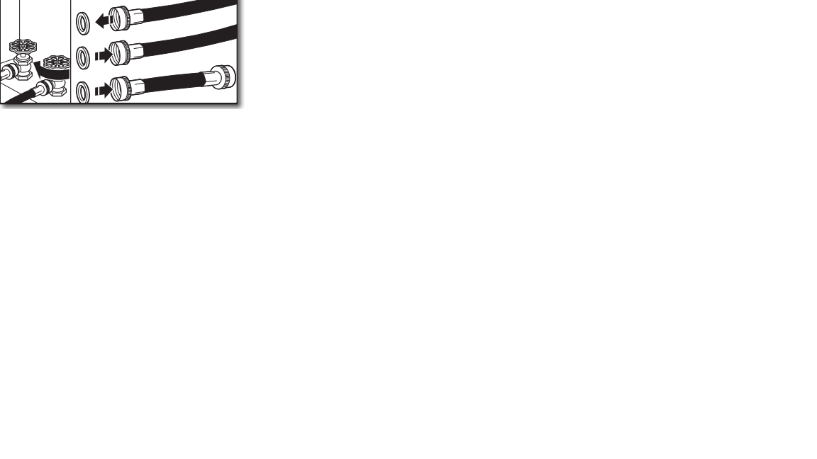
Turn cold water faucet off and remove washer inlet hose. Remove old rubber washer from inlet hose and replace with new rubber washer
2. Attach short hose and “Y” connector
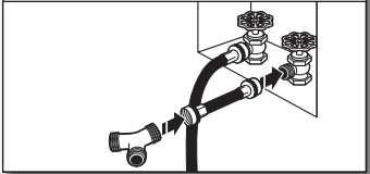
Attach 2 ft. (0.6 m) inlet hose to cold water faucet. Screw on coupling by hand until it is seated on faucet. Then attach “Y” connector to male end of the 2 ft. (0.6 m) inlet hose. Screw on coupling by hand until it is seated on connector.
3. Tighten couplings
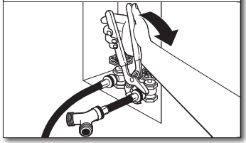
Using pliers, tighten the couplings with additional 2/3 turn. NOTE: Do not overtighten. Damage to the coupling can result.
4. Attach long hose to “Y” connector and tighten couplings
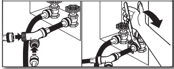
Attach one of the 5 ft. (1.5 m) inlet hose ends to the “Y” connector. Attach washer cold inlet hose to other side of “Y” connector. Screw on coupling by hand until it is seated on connector. Using pliers, tighten the couplings an additional 2/3 turn.
NOTE: Do not overtighten. Damage to the coupling can result.
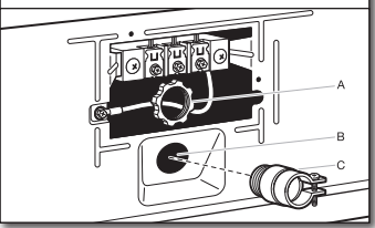
5. Attach long hose to dryer fill valve and tighten coupling
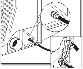
Remove protective cap from water inlet valve. Attach other end of long hose to fill valve at bottom of dryer back panel. Screw on coupling by hand until it is seated on fill valve connector. Using pliers, tighten the couplings an additional 2/3 turn.
NOTE: Do not overtighten. Damage to the coupling can result
6. Turn on cold water faucet
Check that the water faucets are turned on.
7. Check for leaks
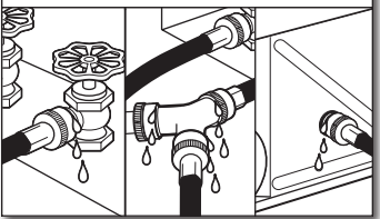
Check for leaks around “Y” connector, faucet, and hoses.
LEVEL DRYER
1. Level dryer
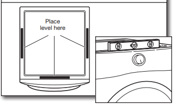
Check levelness of dryer from side to side. Repeat from front to back.
NOTE: The dryer must be level for the moisture sensing system to operate correctly.
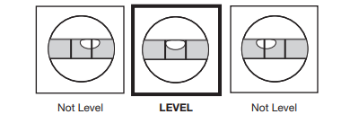
2. Adjust leveling legs
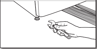
If dryer is not level, prop up using a wood block, use wrench to adjust legs up or down, and check again for levelness. Once dryer is level, make sure all four legs are snug against the floor and the dryer does not rock.
COMPLETE INSTALLATION CHECKLIST
- Check that all parts are now installed. If there is an extra part, go back through steps to see what was skipped.
- Check that you have all of your tools.
- Dispose of/recycle all packaging materials. Be sure the water faucets are on.
- Check for leaks around “Y” connector, faucet, and hoses. Check dryer’s final location. Be sure vent is not crushed or kinked.
- Check that dryer is level. See “Level Dryer.”
- Remove film on console and any tape remaining on dryer. Wipe dryer drum interior thoroughly with a damp cloth to remove any dust.
- Read “Dryer Use” in your Use and Care Guide.
- If you live in a hard water area, use of a water softener is recommended to control the buildup of scale through the water system in the dryer. Over time, the buildup of lime scale may clog different parts of the water system, which will reduce product performance. Excessive scale buildup may lead to the need for certain part replacement or repair
Electric Models:
- Plug into a grounded outlet.
Gas Models:
- Plug into a grounded outlet.
- Check that gas supply is on.
- Check for leaks.
- Check to be sure that the flexible gas line is not crushed or kinked
All Models:
Select a Timed Dry heated cycle and start dryer. Do not select Air Only Temperature setting.
If dryer will not start, check the following:
• Controls are set in a running or On position.
• Start button has been pressed firmly.
• Dryer is plugged into an outlet and/or electrical supply is connected.
• Household fuse is intact and tight, or circuit breaker has not tripped.
• Dryer door is closed
This dryer automatically runs an installation diagnostic routine at the start of its first cycl
NOTE: You may notice an odor when dryer is first heated. This odor is common when heating element is first used. The odor will go away
DOOR REVERSAL (OPTIONAL)
The following instructions are for models with round and square-shaped doors.
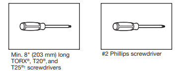
Tools needed:
REVERSE DOOR SWING: ROUND-SHAPED DOOR
1. Disconnect wiring from door
Using a Phillips screwdriver, remove middle screw in hinge. Disconnect wiring. Tuck wiring into opening.
2. Remove door from dryer
IMPORTANT: If the protective film has not yet been removed from the dryer, peel the film from the dryer door before proceeding. Using a T25® screwdriver, remove the four screws securing the door hinge to the dryer and lift the door up and out to remove. Place the door on a soft towel or other non-scratch surface.
3. Move the door strike
Using a T25® screwdriver, remove the two screws securing the door strike to the door frame of the dryer. Rotate the strike 180° and attach to the opposite side of dryer door frame with the two screws removed earlier, as shown.
4. Remove inner door from outer door
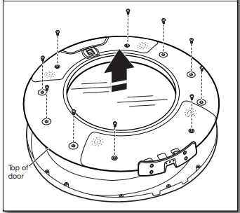
Position the door with the inside of the door facing up. Using a Phillips screwdriver, remove the 10 screws securing the inner door to the outer door
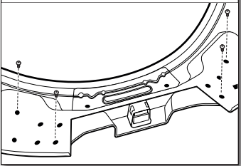
5. Remove hinge
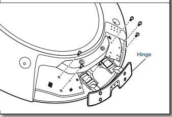
Using a T20® screwdriver, remove the six screws holding the hinge assembly in place.
6. Remove latch
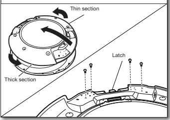
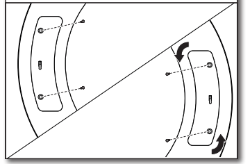
Flip and rotate the inner door 180° so that the thin section is at the top and the thick section is at the bottom. Using a T25® screwdriver, remove the four screws securing the latch plate in place.
7. Reinstall latch on opposite side
Using a T25® screwdriver, reinstall the latch plate on the opposite side from which it was removed with the four screws removed earlier
8. Reinstall hinge assembly on opposite side
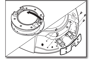
Flip over the inner door to the left. Using a T20® screwdriver, reinstall the hinge assembly on the opposite side from which it was removed.
DOORS WITH ELECTRICAL WIRING:
9. Remove rotating assembly
Lift off inner door assembly. Using a Phillips screwdriver, remove the two screws securing the rotating assembly to the door
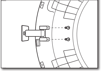
10. Reposition rotating assembly and tubing
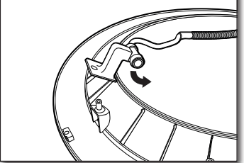
Reposition rotating assembly and tubing 180° to opposite side of the door.
11. Rotate assembly bottom and fasten in place
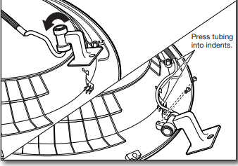
Rotate bottom of assembly 180° towards you and secure assembly with the two screws removed earlier, using a Phillips screwdriver. Press tubing into indents.
IMPORTANT: Make sure to swing hinge down in front of rotating assembly (see Step 12).
Rotate bottom of assembly 180° towards you and secure assembly with the two screws removed earlier, using a Phillips screwdriver. Press tubing into indents.
IMPORTANT: Make sure to swing hinge down in front of rotating assembly (see Step 12).
12. Reinstall inner door assembly
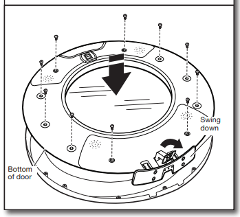
Position the door with the inside of the door facing up. Using a Phillips screwdriver, reinstall the 10 screws removed earlier, securing the inner door to the outer door.
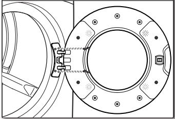
13. Reinstall door on dryer
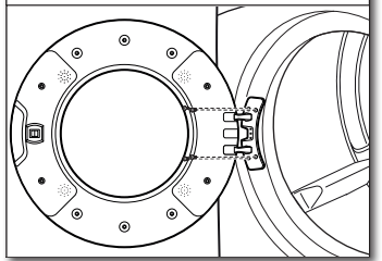
Doors with electrical wiring: Pull the wire through the front panel opening before reinstalling the door. Insert the tabs on the hinge into the mounting slot and slide down to engage the top tab. Secure in place with the four T25® screws removed earlier
14. Reconnect wiring
Plug in wire. Using a Phillips screwdriver, secure the rotating assembly to the hinge with the screw removed earlier.
REVERSE DOOR SWING: SQUARE-SHAPED DOOR
1. Remove door from dryer
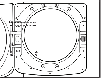
Using a T25® screwdriver, remove the four screws securing the door hinge to the dryer and lift up and out to remove the door. Place the door on a soft towel or other non-scratch surface. Retain or set aside the four screws.
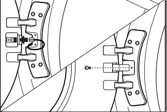
2. Move the door strike
Using a T25® screwdriver, remove the two screws securing the door strike to the door frame of the dryer. Remove the four screws above and below the door strike and set aside for later use. Rotate the strike 180° and attach to the opposite side of dryer door frame, as shown.
3. Remove inner door from outer door
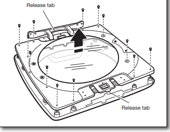
Position the door with the inside of the door facing up. Using a Phillips screwdriver, remove the 13 screws securing the inner door to the outer door. Lift off the inner door and set aside.
NOTE: There is a small release tab on each side of the door. If the inner and outer door do not separate easily, slide a credit card, putty knife, or similar flat object between the inner and outer doors at the locations shown to release the tab.
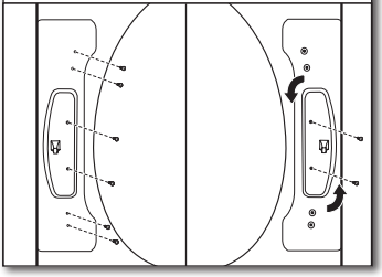
4. Remove hinge and latch from inner door
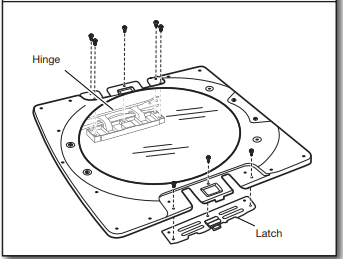
Using a T25® screwdriver, remove the three screws securing the latch plate and the five screws holding the hinge assembly in place.
5. Reinstall hinge and latch on opposite sides
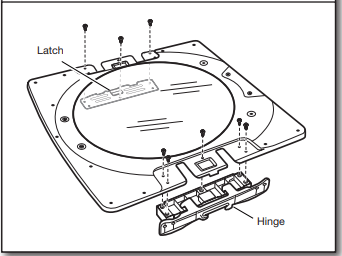
Using a T25® screwdriver, reinstall the latch plate and hinge assembly on the opposite sides from which they were removed
6. Reattach inner door to outer door
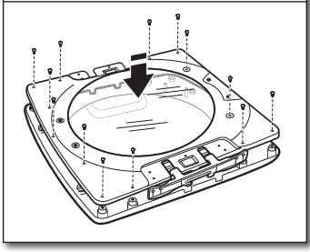
Position the inner door on the outer door assembly. Using a Phillips screwdriver, secure with the 13 screws removed earlier.
7. Reattach door to dryer
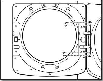
Using a T25® screwdriver, reinstall the four screws securing the door hinge to the dryer