Loading ...
Loading ...
BOX CONTENTS
This box should contain:
1 257.857240 Electric Edger
1 Loose Parts Kit containin_
2 Ea. 3933-1 Screw
2 Ea. 3935 Locknut
1 Ea. 88-4054)0Owner'sManual
TOOLS NEEDED FOR ASSEMBLY
1 Phillips Screwdriver
1 11/32 Box or Crescent Wrench
Remove Edger from carton and examine it
thoroughly to make sure it is not damaged.
NOTE: Your Edger comes packaged wfth protective clips inserted in the .handle tubes. These plastic clips
must be discarded before assembly of the unit,
= === ,_ll,,lll i i i i =l =
ASSEMBLY INSTRUCTIONS
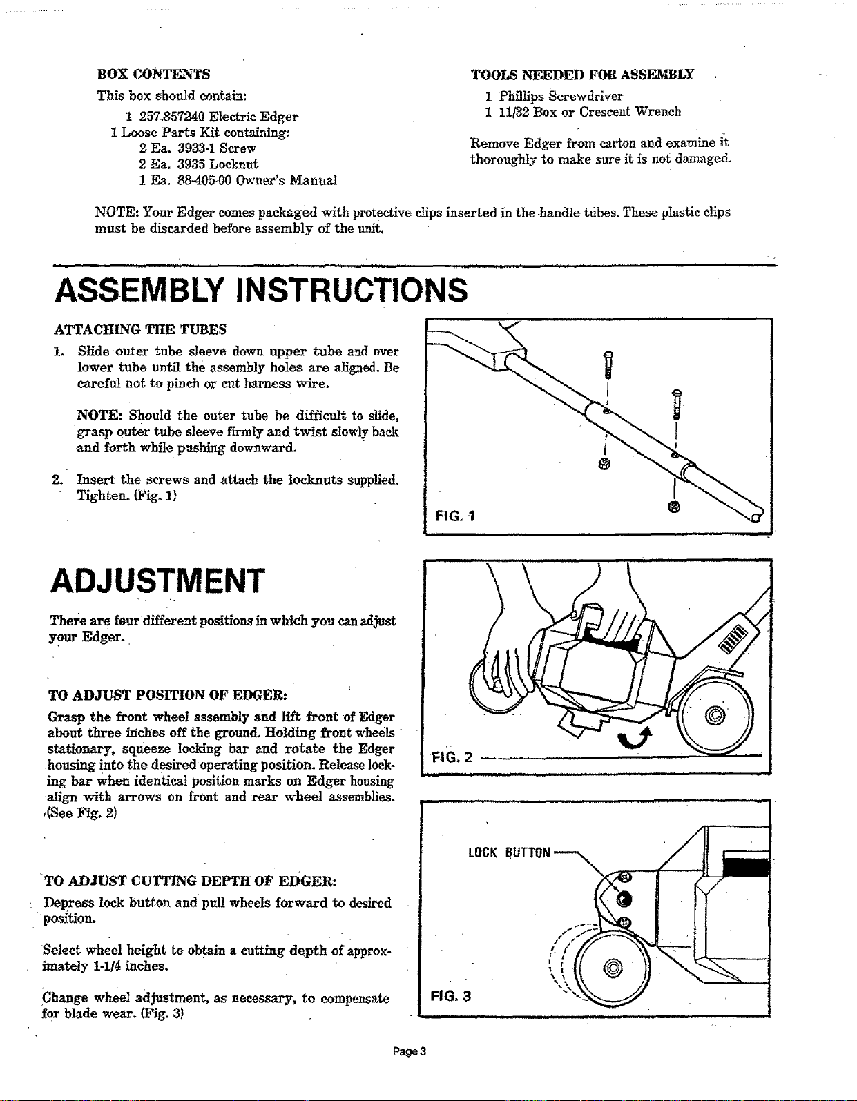
ATTACHING THE TUBES
1. Slide outer tube sleeve down upper tube and over
lower tube until the assembly holes are aligned. Be
careful not to pinch or cut harness wire.
NOTE: Should the outer tube be difficult to slide,
grasp outer tube sleeve firmly and twist slowly back
and forth while pushing downward.
2. Insertthe screws and attachthe locknutssupplied.
Tighten. (Fig. I)
@
ADJUSTMENT
There arefourdifferentpositionsinwhich you canadjust
your Edger.
.TO ADJUST POSITION OF EDGER:
Grasp the frontwheel assemblyand llftfrontofEdger
about threeinchesoffthe ground.Holding frontwheels
stationary,squeeze lockingbar and rotate the Edger
housing intothe desiredoperatingposition.Release10ck-
ing bar when identicalpositionmarks on Edger housing
alignwith arrows on frontand rearwheel assemblies.
,(See Fig. 2)
TO ADJUST CUTTING DEPTH OF EDGER:
: Depress lock button and pul! wheels forward to desired
position.
Selectwheel heighttoobtaina cuttingdepth ofapprox-
imately1-1/4inches.
iChange wheel adjustment, as necessary, to compensate
for blade wear. (Fig. 3}
Page3
Loading ...
Loading ...
Loading ...