Loading ...
Loading ...
Loading ...
20 EX17DT and EX22DT Installation and Operation Manual
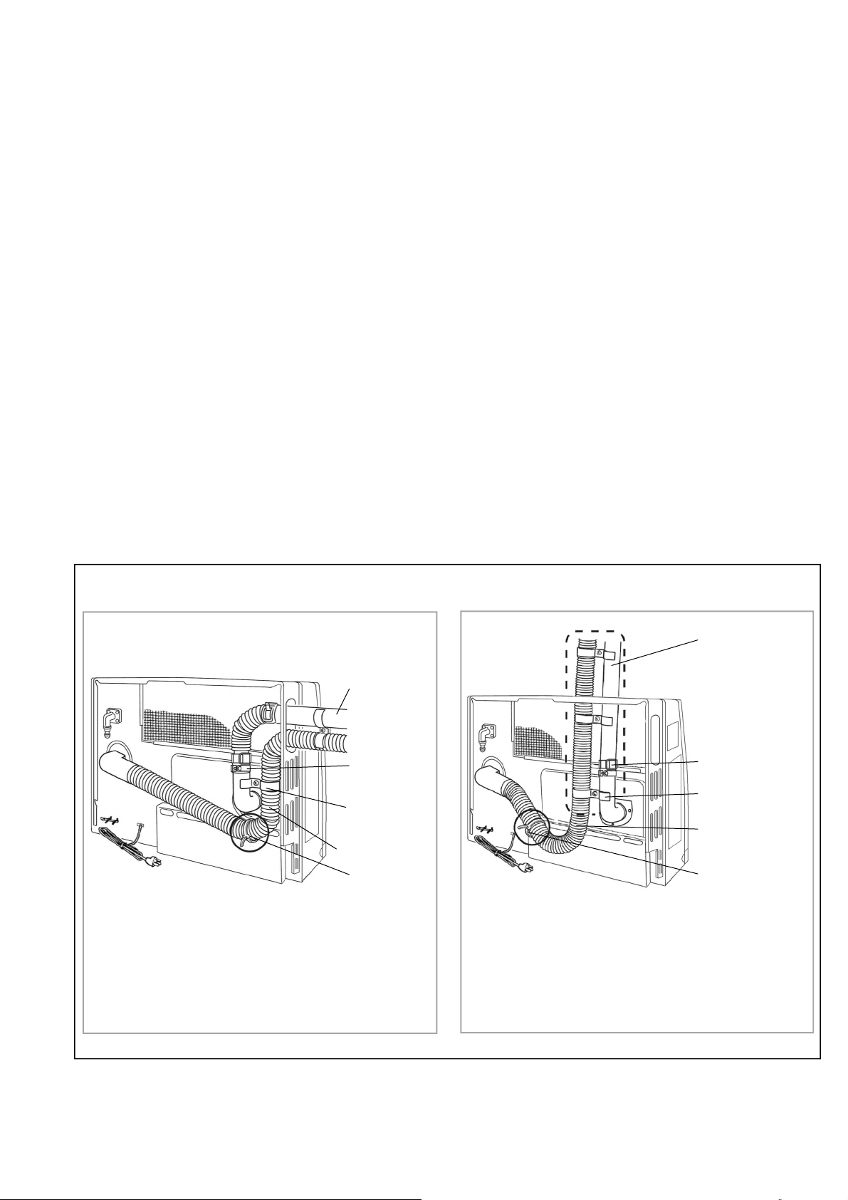
Extension lines are through the side panel of the
furnace.
It is not possible to position the extension lines
through the other side panel of the furnace.
One elbow is shown. One additional elbow may
be added.
Steps 1-6 (above) must be followed.
Plastic Tie
Air Intake Hose
Exhaust Line
Pipe
Stopper A
Pipe Clamp
Extension lines are through the top panel of the
furnace above where the exhaust exits the
furnace.
No elbows are shown. Two additional elbows
may be added.
Steps 1-6 (above) must be followed.
Plastic Tie
Exhaust Line
Pipe Stopper A
Pipe Clamp
Air Intake Hose
Guidelines
1. The maximum vent length is 13 ft (4 m) with 3 bends. The bent pipe attached to the furnace
does not count toward the max limit of 3 bends.
2. Maximum vertical length allowed is 10 feet (3 m).
3. If the extension is longer than 10 feet (3 m), the condensate may overflow the condensation
pan. Therefore, extension exceeding this length should drain to the outside and sloped 3°
downward.
4. Do not allow any low points or sagging in the exhaust line. Otherwise, condensate may block
the exhaust and affect combustion.
5. Vent extensions installed in unconditioned air space must be insulated with high temperature
insulation and must be accessible.
6. Vent extensions must not be concealed per NFPA 54 and must be accessible allowing
inspection and repair. Decorative covers are available from Rinnai.
7. Clearances:
Exhaust pipe to combustibles: 1 in. (25.4 mm)
Exhaust pipe to non-combustibles: 0 in. (0 mm)
Configurations
The following figures show the possible ways that the extension exhaust line and air intake hose may
be directed away from the furnace. All views are from behind the furnace. For your configuration,
position the air intake hose as shown in the following figures.
Figure 16
Correct Configurations
Loading ...
Loading ...
Loading ...