Loading ...
Loading ...
Loading ...
PRE-INSTALLATION
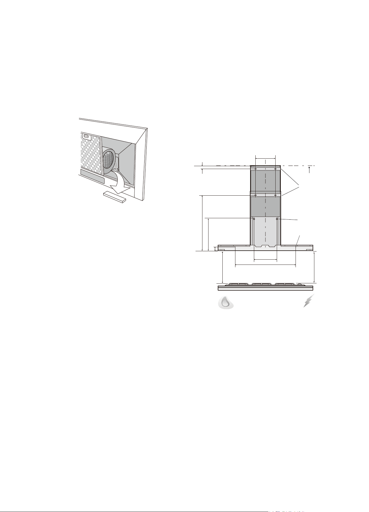
Before installing the cooker hood, peel off any protective
plastic covering and remove polystyrene from inside behind
the fan motor. See diagram below.
LOCATION
The underside of the hood body must be a minimum
of 600mm* above an electric cooktop and 650mm*
above a gas cooktop and a maximum height of 800mm.
*If the instructions of the hob specify a greater distance than the minimum above,
then that shall be the minimum height for installation.
INSTALLATION
1. Using a spirit level mark a vertical centre line on the
wall where the hood is to be positioned, and a
horizontal line at the hood base position (refer
Fig. 6 below).
2. Mark the location for flue cover wall mounting brackets
and rangehood mounting points and anti-tilt fixing
points above the hood base using the hood base as
the reference point (Fig. 6 below).
3. Install flue cover wall mounting brackets with suitable
fixings. Install suitable screws for rangehood mounting
points (to support a total weight of 30kg) to the wall as
marked (Fig. 7).
INSTALLATION
Fig. 6
6
Top of hob
250mm
580mm
250mm
23.5mm
GAS
ELECTRIC
Ceiling
Flue cover
wall mounting
brackets
Rangehood
mounting points
Anti-tilt fixing points
Hood base
Min 600mm
Max 800mm
Min 650mm
Max 800mm
286mm
559mm
36mm
PRE-INSTALLATION
Before installing the cooker hood, peel off any protective
plastic covering and remove polystyrene from inside behind
the fan motor. See diagram below.
LOCATION
The underside of the hood body must be a minimum
of 600mm* above an electric cooktop and 650mm*
above a gas cooktop and a maximum height of 800mm.
*If the instructions of the hob specify a greater distance than the minimum above,
then that shall be the minimum height for installation.
INSTALLATION
1. Using a spirit level mark a vertical centre line on the
wall where the hood is to be positioned, and a
horizontal line at the hood base position (refer
Fig. 6 below).
2. Mark the location for ue cover wall mounting brackets
and rangehood mounting points and anti-tilt xing
points above the hood base using the hood base as
the reference point (Fig. 6 below).
3. Install ue cover wall mounting brackets with suitable
xings. Install suitable screws for rangehood mounting
points (to support a total weight of 30kg) to the wall as
marked (Fig. 7).
INSTALLATION
ceiling
235mm
580mm
25mm
270mm
250mm
36mm
Min. 650mm
Max. 800mm
Fig. 6
250mm
Loading ...
Loading ...
Loading ...