Loading ...
Loading ...
Loading ...
OPERATION
25
ENGLISH
Self-Diagnosis
FUNCTION
If the unit has a malfunction, a green OPERATION LED located on the Display PCB used by the unit to indi-
cate the error codes.
USE
If the customer has to register a complaint to the service center, he can be very clear about registering the
complaint that what is happening & by referring the user's manual the customer can clearly define the prob-
lem.
So that the engineer should go fully prepared with the prescribed tools to be used regarding that problem. It
also keeps the customer aware about the unit.
Here are some of the problems defined below for which the LED indicates by flashing.
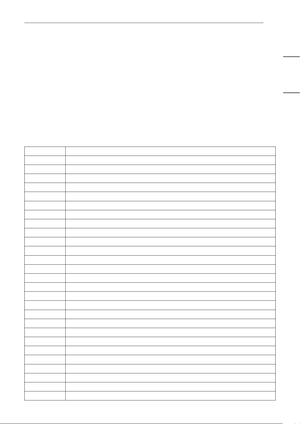
The error codes are the mentioned which is as follows:
• Electrical Controls
Error Code Descriptions
01 Indoor unit room temperature sensor error
02 Indoor unit inlet pipe sensor error
03 Wired remote control error
05 Communication error between indoor and outdoor units
07 Thermostat Wiring Error
09 Indoor unit EEPROM error
10 Indoor unit BLDC motor fan lock
21 DC Peak (IPM Fault)
22 CT 2 (Max CT)
23 DC Link Low Volt
26 DC Comp Position Error
27 PSC Fault
29 Comp Phase Over-Current
32 Inverter Compressor D-Pipe Overheat
36 (38) Refrigerant Leakage Detection
41 D-Pipe Sensor Error
44 Outdoor Air Sensor Error
45 Cond. Middle Pipe Sensor Error
48 Cond. Pipe Error (Open / Short)
51 Excess Capacity (Mismatching between In/Outdoor unit)
53 Communication Error (IN-OUT)
60 EEPROM Check Sum Error
61 Cond. Pipe High
62 Heat Sink Sensor Temp. High
65 Heatsink Th Error
67 BLDC Motor Fan Lock
72 Detect 4 Way Valve Transfer Failure 7 Times
Loading ...
Loading ...
Loading ...