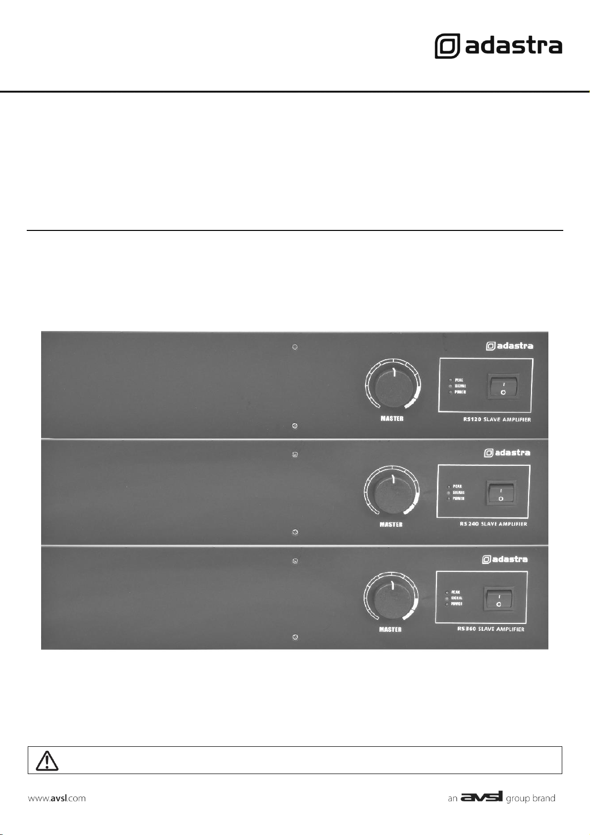
RS SERIES
Rackmount 100V slave amplifiers
Item ref: 953.120UK, 953.121UK, 953.122UK
User Manual
Version 1.1
Caution: Please read this manual carefully before operating
Damage caused by misuse is not covered by the warranty
RS Series User Manual
Introduction
Thank you for choosing the Adastra RS-series rackmount 100V slave amplifier as part of your public address system. This amplifier is
designed to offer high quality, dependable service for mobile and installed systems. Please read this manual fully and follow the
instructions to achieve the best results with your new purchase and to avoid damage through misuse.
Warning
To prevent the risk of fire or electric shock, do not expose any components to rain or moisture.
If liquids are spilled on the casing, stop using immediately, allow unit to dry out and have checked by qualified personnel before
further use. Avoid impact, extreme pressure or heavy vibration to the case
No user-serviceable parts inside. Do not open. Refer all servicing to qualified service personnel.
Safety
• Check for correct mains voltage and condition of IEC lead before connecting to power outlet
• Use double insulated speaker wire with adequate current rating for 100V speaker connections
• Do not use 8Ω and 100V terminals at the same time
• Do not allow any foreign objects to enter the case or through the ventilation grilles
Placement
• Keep out of direct sunlight and away from heat sources
• Keep away from damp or dusty environments
• For rack-mounting, ensure adequate support for the weight of the amplifier
• Ensure adequate air-flow and access to controls and connections
Cleaning
• Use a soft cloth with a neutral detergent to clean the casing as required. Do not use strong solvents.
• Use a vacuum cleaner to clear ventilation grilles of any dust or debris build-ups
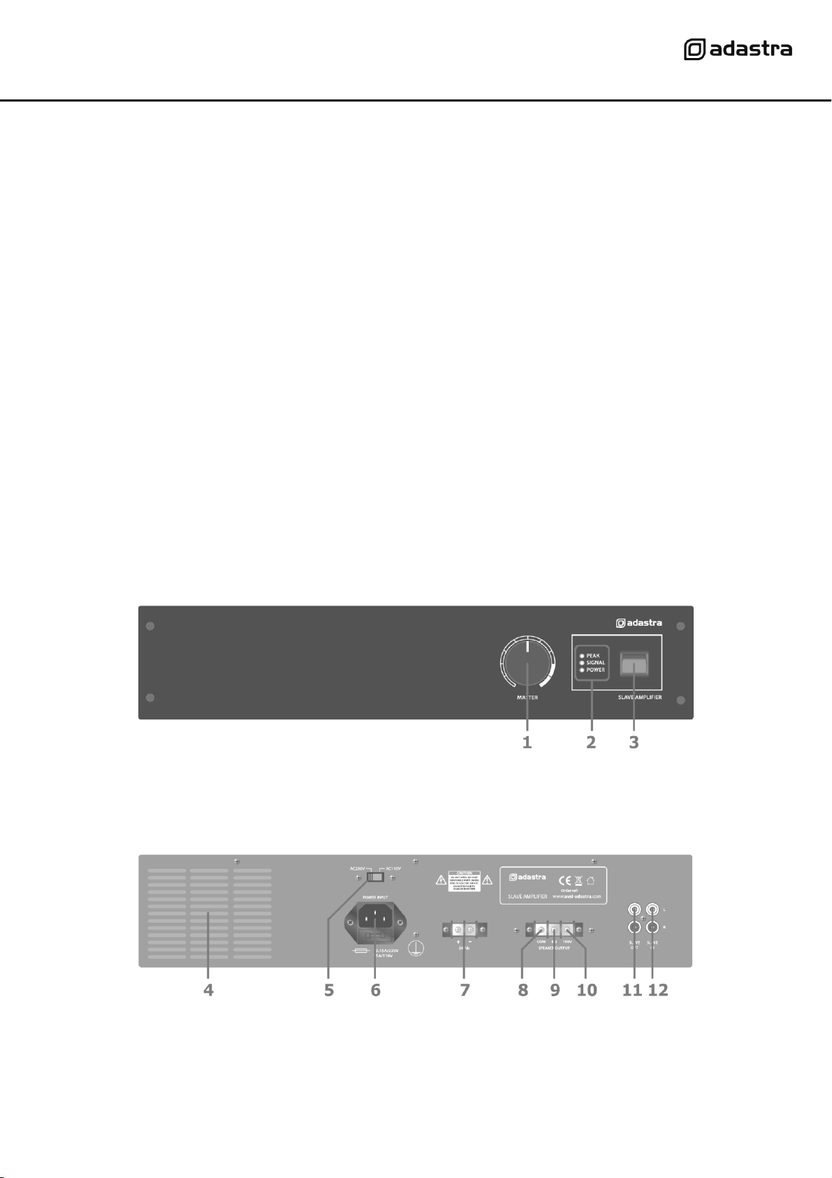
Front panel
Rear panel
1.
MASTER volume control
2.
POWER, SIGNAL, PEAK LED indicators
3.
Power switch
4.
Ventilation grille - do not cover
9.
8Ω speaker terminal
5.
Mains power voltage switch
10.
100V speaker terminal
6.
IEC mains power inlet & fuse holder
11.
SLAVE OUT connectors (RCA)
7.
24Vdc power connection (not RS360)
12.
SLAVE IN connectors (RCA)
8.
COM speaker terminal
RS Series User Manual
Connection and setup
Connect the rear IEC inlet (6) to the mains using the supplied mains lead (or an equivalent approved type). Ensure that
the voltage is correct as indicated on the voltage selector (5) and that the mains outlet is switched on.
Alternatively, the RS120 and RS240 can be powered by a 24V battery, such as a lorry or boat battery, by connecting the
“+” and “-” of the battery to the 24Vdc INPUT (7) on the rear panel. Ensure that DC cables are capable of handling the
current (10A min. recommended)
The RS series amplifiers are intended to be fed from a mixer or mixer-amplifier signal output, providing additional power
amplification for 100V speaker systems. The signal input should be connected to the SLAVE IN dual RCA connectors (12)
on the rear panel. The RS series slave amplifiers are mono, so any stereo input signals will be summed together to
provide a monaural output. Further slave amplifiers can be connected from the rear SLAVE OUT RCA sockets (11),
allowing banks of amplifiers to operate together in large public address systems.
Speaker outputs
The RS series slave amplifiers can be used either as 100V line amplifiers or standard low impedance power amplifiers.
These 2 configurations cannot be used together, so it is important to decide which method will be used at the start.
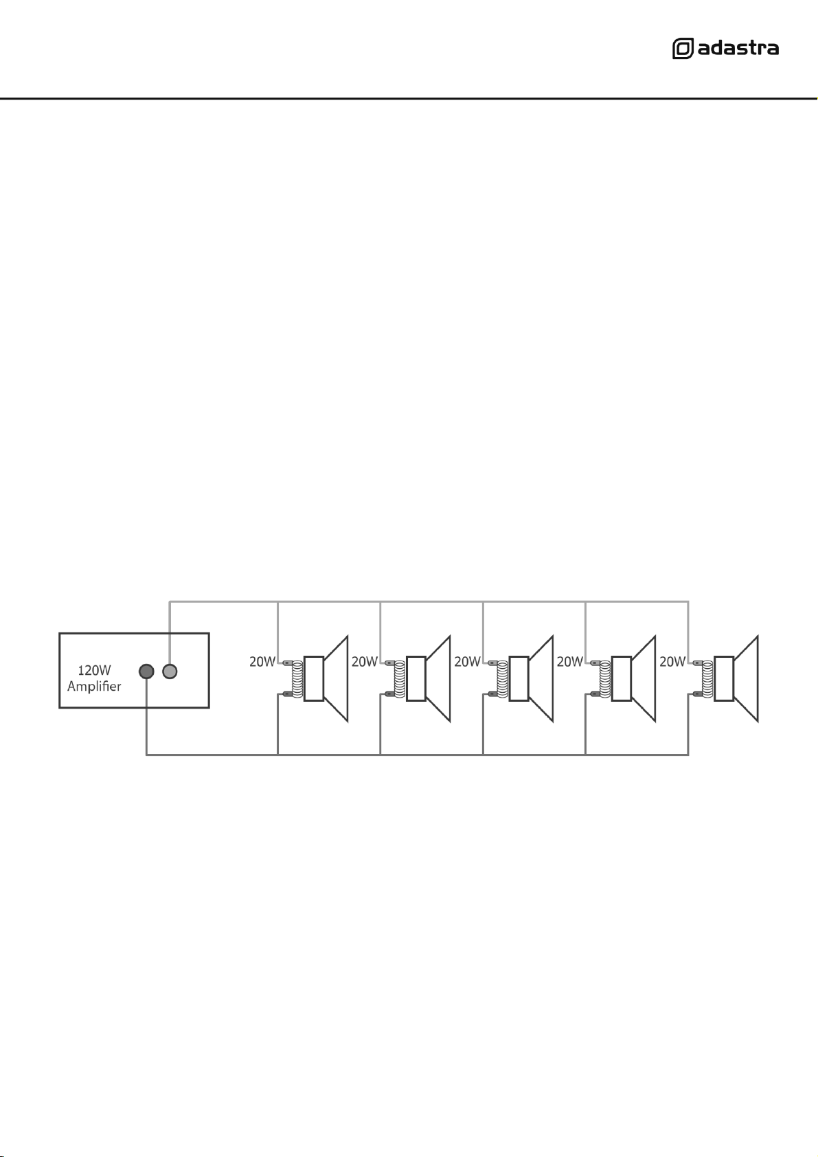
100V line systems
For 100V line systems, connect the amplifier to the first speaker in the system using double-insulated speaker wire which
has adequate current rating to handle the total output of the amplifier.
Connect the “100V” (10) output terminal to the positive (+) connection of the speaker and “COM” output (8) to the
negative (-) connection of the speaker. Connect further speakers in parallel to the first speaker with all positive terminals
and connected together and all negative terminals connected together as shown below.
A 100V line speaker system can comprise of many speakers connected together. The determining factor for how many
speakers can be used on a single amplifier is the power rating. For most purposes, it is advised to connect as many
speakers as needed with a combined wattage of no more than 90% of the amplifier’s output power rating.
The terminals of a 100V speaker are connected to a transformer and in some cases, this transformer may be “tapped” for
different power ratings. These tappings can be used to adjust the wattage (and output volume) of each speaker in the
system to help achieve the ideal total power of the system for the amplifier.
Low impedance systems
The RS series slave amplifiers can provide an output for a single 8Ω speaker by connecting the “8Ω” output (9) to the
positive (+) speaker connection and “COM” output (8) to the negative (-) speaker connection. It is important to ensure
that the speaker load is no less than 8Ω and that the power handling of the speaker is equal to or greater than the
output power of the amplifier.
RS Series User Manual
Operation
When all connections to the amplifier are made, turn the MASTER volume control (1) fully down and switch on the power
(3) and the power LED will illuminate. Ensuring that the signal is active on the SLAVE IN inputs, turn up the MASTER
gradually to the maximum required volume level.
The output of the amplifier is represented on the SIGNAL LED and when the amplifier is running at its peak output, a
PEAK LED will illuminate. Care should be taken that the Red PEAK LED is only lit momentarily during use. Anything longer
than a short flash of this LED may be indicating distortion or clipping of the output signal and the MASTER volume should
be turned down.
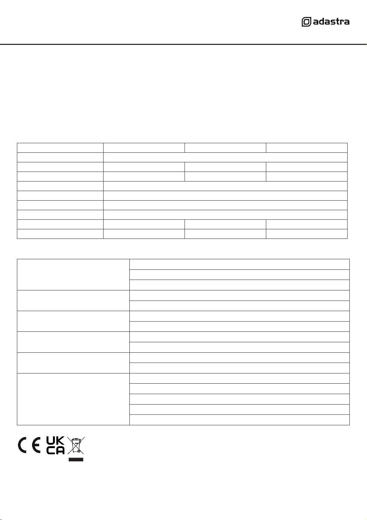
Specifications
Model
RS120
RS240
RS360
Power supply
110/230Vac, 50/60Hz (IEC)
DC power
24Vdc screw terminals
24Vdc screw terminals
N/A
Output power: RMS
120Wrms
240Wrms
360Wrms
Output: Line
RCA slave out
Input
RCA slave in
Controls
Master volume
THD
<1.0%
Dimensions
433 x 363 x 89mm
433 x 363 x 89mm
433 x 403 x 89mm
Weight
8.88kg
10.06kg
11.60kg
Troubleshooting
No power LED on control panel
Ensure IEC lead is in good condition and connected properly
If 24Vdc power input is being used, check battery is charged
Ensure POWER switch is on and check mains inlet fuse
Power LED is on but no other LEDs and no
output
Check input signals and condition of input connection leads
Check MASTER volume control is turned up
POWER and SIGNAL LEDs lighting but no
output
Check speaker output terminals are connected correctly
Check speakers are working (test on another amp if available)
Output is very loud or distorted
Check level of input signal is not too high
Reduce MASTER volume level
Output is working but at very low level
Check SLAVE IN signal level is not too low
Increase MASTER volume level
Amplifier overheating
Ensure cooling vents are clear from debris and dust
Check that 8Ω speakers are not connected to the 100V terminal
Ensure total 100V speaker wattage is lower than amplifier rating
Ensure that 100V and 8Ω speakers are not both connected
Ensure that total load connected to 8Ω output is not less than 8Ω
Disposal: The “Crossed Wheelie Bin” symbol on the product means that the product is classed as Electrical or
Electronic equipment and should not be disposed with other household or commercial waste at the end of its
useful life. The goods must be disposed of according to your local council guidelines.
Errors and omissions excepted. Copyright© 2021.
AVSL Group Ltd. Unit 2-4 Bridgewater Park, Taylor Rd. Manchester. M41 7JQ
AVSL (EUROPE) Ltd, Unit 3D North Point House, North Point Business Park, New Mallow Road, Cork, Ireland.