Loading ...
Loading ...
Loading ...
Theoperationof anylawn
mowercanresultin foreign
objectsthrown intothe
eyes,whichcanresultin
severeeyedamage.Always
wearsafetyglassesor eyeshieldswhile
operatingyourlawnmoweror performing
anyadjustmentsor repairs.Werecom-
mendastandardsafetyglassesorwide
visionsafetymaskwornoverspectacles.
HOWTO USEYOUR LAWN MOWER
ENGINE SPEED
The engine speed was set at the factory
for optimum performance. Speed is not
adjustable.
ENGINE ZONE CONTROL
_CAUTION: Federal regulations require
an engine control to be installed on this
lawn mower in order to minimize the
risk of blade contact injury. Do not under
any circumstances attempt to defeat the
function of the operator control. The blade
turns when the engine is running.
• Your lawn mower is equipped with an
operator presence control bar which
requires the operator to be positioned
behind the lawn mower handle to start
and operate the lawn mower.
DRIVE CONTROL
• Self-propelling is controlled by hold-
ing the operator presence control bar
down to the handle and pulling the drive
control lever rearward to the handle.
The farther toward the handle the lever
is pulled, the faster the unit will travel.
• Forward motion will stop when either
the operator presence control bar or
drive control lever are released. To stop
forward motion without stopping engine,
release only the drive control lever. Hold
operator presence control bar down
against handle to continue mowing
without self-propelling.
NOTE: If after releasing the drive control
the mower will not roll backwards, push
the mower forward slightly to disengage
drive wheels.
• To keep drive control engaged when
turning corners, push down on the
handle to lift the front wheels off the
ground while turning lawn mower.
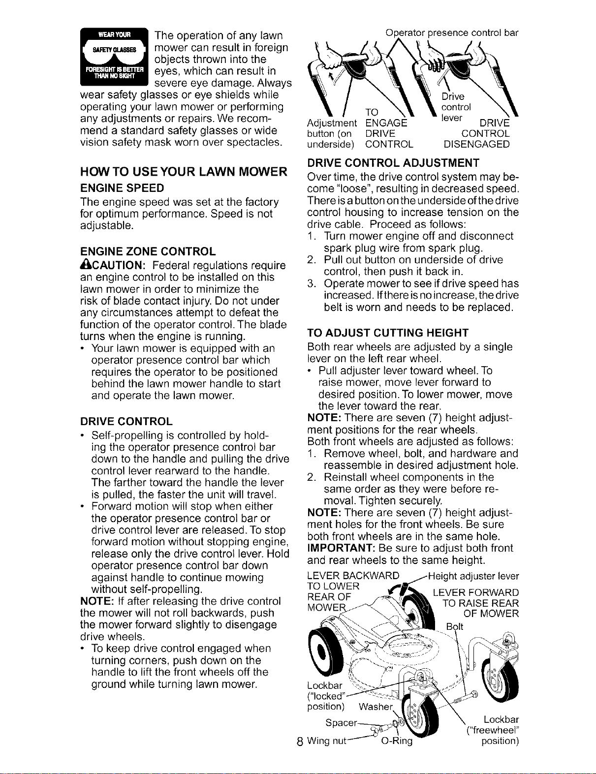
OI controlbar
Drive
control
TO lever
Adjustment ENGAGE DRIVE
button (on DRIVE CONTROL
underside) CONTROL DISENGAGED
DRIVE CONTROL ADJUSTMENT
Over time, the drive control system may be-
come "loose", resulting in decreased speed.
There isa button on the underside of the drive
control housing to increase tension on the
drive cable. Proceed as follows:
1. Turn mower engine off and disconnect
spark plug wire from spark plug.
2. Pull out button on underside of drive
control, then push it back in.
3. Operate mower to see ifdrive speed has
increased. Ifthere isno increase, the drive
belt is worn and needs to be replaced.
TO ADJUST CUTTING HEIGHT
Both rear wheels are adjusted by a single
lever on the left rear wheel.
• Pull adjuster lever toward wheel. To
raise mower, move lever forward to
desired position. To lower mower, move
the lever toward the rear.
NOTE: There are seven (7) height adjust-
ment positions for the rear wheels.
Both front wheels are adjusted as follows:
1. Remove wheel, bolt, and hardware and
reassemble in desired adjustment hole.
2. Reinstall wheel components in the
same order as they were before re-
moval. Tighten securely.
NOTE: There are seven (7) height adjust-
ment holes for the front wheels. Be sure
both front wheels are in the same hole.
IMPORTANT: Be sure to adjust both front
and rear wheels to the same height.
LEVER BACKWARD
TO LOWER
REAR OF
MOWER
adjuster lever
LEVER FORWARD
TO RAISE REAR
OF MOWER
Bolt
Lockbar
("locked'
position)
8 Wing
Washer
Lockbar
("freewheel"
O-Ring position)
Loading ...
Loading ...
Loading ...