Loading ...
Loading ...
Loading ...
61
Electrical System Installation
Due to our policy of continuous product innovation, some specifications may change without notification.
©LG Electronics U.S.A., Inc., Englewood Cliffs, NJ. All rights reserved. “LG” is a registered trademark of LG Corp.
ELECTRICAL SYSTEM INSTALLATION
Outdoor Unit Electrical Connections
Connecting the Conduit at the
Outdoor Unit
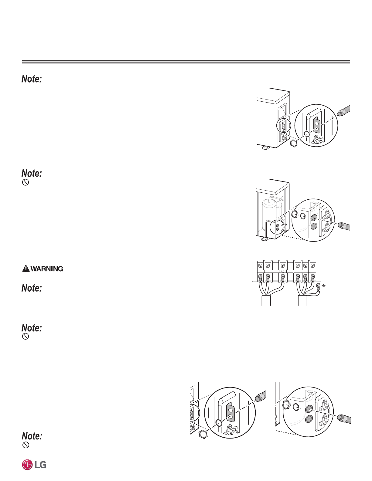
HYV3 outdoor units have a either bracket, or holes on the side to
help access the control panel. Insert the other end of the conduit
to the outdoor unit access hole with a grommet and washer (field-
supplied with the connector) as shown.
Do not install power wiring to the outdoor unit and the communication / connection (power) cable to the indoor unit in the same conduit. Use
separate conduits for the separate access holes. Communication problems will occur.
Loose wires can cause the wiring to burn out, damaging the outdoor unit.
6. Unscrew the screws to the cable clamps, and then open the cable clamps. There is one cable
clamp for the power wiring to the outdoor unit, and one cable clamp for the communication /
connection (power) cable to the indoor unit.
7. Guide the outdoor unit power wiring, and communications / connection (power) cable through
the separate access holes in the bracket (LAU090-120HYV3), or through the separate ac-
cess holes (LAU150-180-240HYV3) (see images at right). If installing conduits to protect the
communication / connection (power) cable, see “Using a Conduit for Indoor Unit Wiring / Cable
Installation”.
Do not install power wiring to the outdoor unit and the communication / connection (power) cable to
the indoor unit in the same conduit. Use separate conduits for the separate access holes. Communica-
tion problems will occur.
8. Using a JIS screwdriver, securely connect wires as shown. See also indoor unit wiring diagram
found on its bottom cover, and outdoor unit wiring diagram on the inside of its chassis cover.
• Each wire must be individually and securely attached to each terminal.
• Outdoor unit wire color and terminal number must match the indoor unit wire color and terminal
number.
• Pay attention to the location / connection of the ground cable.
• Maintain a minimum of 1/4 inches of wire length from terminal block to conduit / bundle.
Loose wires will cause electric shock, bodily injury and / or death.
Loose wires can cause the wiring to burn out, damaging the outdoor unit.
9. Close the cable clamps, and secure them with the screws.
Do not secure the outdoor unit power wiring and the communication / connection (power)
cable to the indoor unit using the same cable clamp. Use the two separate clamps. Communication problems will occur.
10. When finished, reattach the piping cover or side panel (depending on model) to the outdoor unit with the screw(s).
Figure 100: LAU090HYV3 / LAU120HYV3
Outdoor Unit Wiring / Cable Access Holes.
Figure 101: LAU150HYV3 / LAU180HYV3 /
LAU240HYV3 Outdoor Unit Wiring / Cable
Access Holes.
Terminal Connections
for Outdoor Unit
Power Supply Wiring
Terminal Connections for
Communication / Connection
(Power) Cable from
Outdoor Unit to Indoor Unit
1(L1) 2(L2) 1(L1) 2(L2) 3
Figure 102: Outdoor Unit Wiring / Cable Connec-
tions.
Figure 103: LAU090-120HYV3 Out-
door Unit Conduit Assembly.
Figure 104: LAU150-180-240HYV3
Outdoor Unit Conduit Assembly.
Loading ...
Loading ...
Loading ...