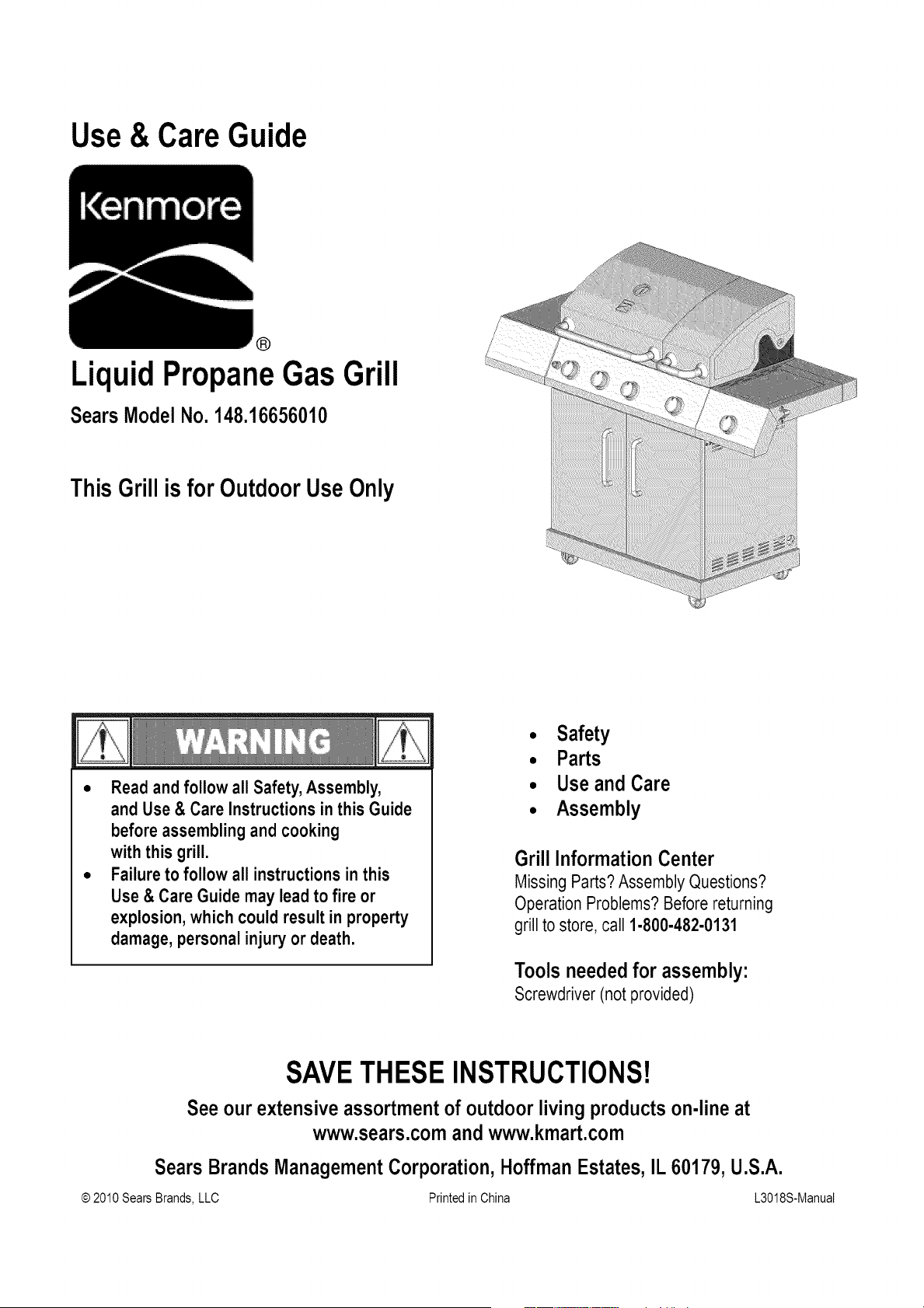
Use & Care Guide
®
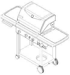
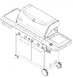
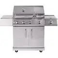
LiquidPropaneGas Grill
Sears ModelNo. 148.16656010
This Grill is for OutdoorUse Only
• Read and follow all Safety,Assembly,
and Use & Care Instructions in this Guide
before assembling and cooking
with this grill.
• Failure to follow all instructions in this
Use & Care Guide may leadto fire or
explosion, which could result in property
damage, personal injury or death.
• Safety
• Parts
• Useand Care
• Assembly
Grill InformationCenter
Missing Parts?Assembly Questions?
Operation Problems?Before returning
grill to store, call 1-800-482-0131
Tools needed for assembly:
Screwdriver(notprovided)
SAVETHESEINSTRUCTIONS!
See our extensive assortmentof outdoor living productson-line at
www.sears.comand www.kmart.com
Sears Brands ManagementCorporation,HoffmanEstates,IL 60179,U.S.A.
© 2010Sears Brands,LLC Printedin China L3018S-ManuaE
If you smell gas:
1. Shut off gas to the appliance.
2. Extinguishany open flame.
3. Open lid.
4. If odor continues, keep away from the
appliance and immediately call your gas
supplier or your fire department.
CALIFORNIA PROPOSITION 65
1. Combustion by-products produced when using
this product contain chemicals known to the State
of California to cause cancer, birth defects, and
other reproductive harm.
2. This product contains chemicals, including lead
and lead compounds, known to the State of
California to cause cancer, birth defects or other
reproductive harm.
Washyour hands after handling this product.
1. Do not store or use gasoline or other
flammable liquids or vapors in the vicinity
of this or any other appliance.
2. An LP cylinder not connectedfor use shall
not be stored in the vicinity of this or any
other appliance.
Call Grill Service Center For Help And Parts
If you have questions or need assistance during assembly,
please call 1-800-482-0131.You will be speaking to a
representative of the grill manufacturer and not a Sears
employee. To order new parts call Sears at
1-800-4-MY-HOME.
Product Record
IMPORTANT: Fill out the product record information
below.
Model Number
Serial Number
See rating label on grill for serial number.
Date Purchased
Installation Safety Precautions
• Use grill, as purchased, only with LP (propane) gas and the
regulator/valve assembly supplied. A conversion kit must
be purchased for use with natural gas.
• Grill installation must conform with local codes, or in their
absence of local codes, with either the National Fuel Gas
Code, ANSI Z223.1/NFPA 54, Natural Gas and Propane
Installation Code, CSA B149.1, or Propane Storage and
Handling Code, B149.2, or the Standard for Recreational
Vehicles,ANSI A 119.2/NFPA 1192, and CSA Z240 RV
Series, Recreational Vehicle Code, as applicable.
• All electrical accessories (such as rotisserie) must be
electrically grounded in accordance with local codes, or
National Electrical Code, ANSI/NFPA 70 or Canadian
Electrical Code, CSA C22.1. Keep any electrical cords
and/or fuel supply hoses away from any hot surfaces.
• This grill is safety certified for use in the United States
and/or Canada only. Do not modify for use in any other
location. Modification will result in a safety hazard.
Safety Symbols
The symbols and boxes shown below explain what each
heading means. Read and follow all of the messages found
throughout the manual.
DANGER: Indicates an imminently hazardous
situation which, if not avoided, will result in death or
serious injury.
For residential use only. Do not use for
commercial cooking.
WARNING: Indicates an potentially hazardous
situation which, if not avoided, could result in death
or serious injury.
CAUTION:Indicatesapotentiallyhazardous
situationorunsafepracticewhich,ifnotavoided,
mayresultinminorormoderateinjury.
cancelforanyreasonduringtheproductwarrantyperiod,we
willprovideafullrefund.Or,aproratedrefundanytimeafter
theproductwarrantyperiodexpires.PurchaseyourRepair
ProtectionAgreementtoday!
Somelimitationsandexclusionsapply.
Forpricesandadditionalinformationcall1-600-627-6655.
SearsInstallationService
For Sears professional installation of home appliances, garage
door openers, water heaters, and other major home items, in
the U.S.A. call 1-600-4-MY-HOME®
For Your Safety .................................. 2
Grill Service Center............................... 2
Product Record Information ........................ 2
Safety Symbols.................................. 2
Installation Safety Precautions ....................... 2
Kenmore Grill Warranty ........................... 3
Use and Care ................................ 4-10
Natural Gas Conversion Box ...................... 11
Notes.......................................... 12
Parts List ...................................... 13
Parts Diagram................................... 14
Assembly .................................... 15-25
Troubleshooting............................... 26-27
Repair Protection Agreements
Congratulations on making a smart purchase. Your new
Kenmore ®productis designed and manufactured for years of
dependable operation. But like all products, it may require
repair from time to time. That's when having a Repair
Protection Agreement can save you money and aggravation.
Purchase a Repair Protection Agreement now and protect
yourself from unexpected hassle and expense.
Here's what the Repair Protection Agreement includes:
[] Expert service by our 10,000 professional repair
specialists
[] Unlimited service and no charge for parts and labor on
all covered repairs
[] Product replacement up to $1500 if your covered
product can't be fixed
[] Discount of 10%from regular price of service and
related installed parts not covered by the agreement; also,
10% off regular price of preventive maintenance check
[] Fast help by phone - we call it Rapid Resolution -
phone support from a Sears representative. Think of us
as a "talking owner's manual."
Once you purchase the Repair Protection Agreement, a simple
phone call is all that it takes for you to schedule service. You
can call anytime day or night, or schedule a service
appointment online.
The Repair Protection Agreement is a risk-free purchase. If you
Kenmore FullWarranty
If this grill fails due to a defect in material or workmanship
within one year from the date of purchase, call 1-800-4-MY-
HOME® to arrange for free repair (or replacement if repair
proves impossible).
Limited Warranty on Burners
For ten years from the date of purchase, any stainless steel
burner that rusts through will be replaced free of charge. After
the first year from the date of purchase, you pay for labor if
you wish to have it installed.
All warranty coverage excludes ignitor batteries and grill part
paint loss, discoloration or rusting, which are either
expendable parts that can wear out from normal use within
the warranty period, or are conditions that can be the result
of normal use, accident or improper maintenance.
All warranty coverage is void if this grill is ever used for
commercial or rental purposes.
All warranty coverage applies only if this grill is used in the
United States.
This warranty gives you specific legal rights, and you may
also have other rights which vary from state to state.
Sears, Roebuck and Co., Hoffman Estates, IL 60179

• NEVER store a spare LP cylinder under or near
the grill appliance or in an enclosed area.
• Never fill a cylinder beyond 80% full.
• If the information in the two points above is not
followed exactly, a fire causing death or serious
injury may occur.
° An over filled or improperlystored cylinder is a
hazard due to possible gas release from the
safety relief valve. This could cause an intense
fire with risk of property damage, serious injury
or death.
° If you see, smell or hear gas escaping,
immediatelyget away from the LP cylinder and
grill appliance and call your fire department.
LP Cylinder
• The LP cylinder used with your grill must meet the
following requirements:
• Use LP cylinders only with these required measurements: 12"
(30.5cm) (diameter) x 18" (45.7 cm) (tall) with 20 lb. (9 kg.)
capacity maximum.
• LP cylinders must be constructed and marked in accordance
with specifications for LP cylinders of the U.S. Department of
Transportation (DOT) or for Canada, CAN/CSA-B339,
cylinders, spheres and tubes for transportation of dangerous
goods. Transport Canada (TC). See LP cylinder collar for
marking.
• LP cylinder valve must have:
• Type 1 outlet compatible with
regulator or grill.
• Safety relief valve.
• UL listed Overfill Protection OPD HandWheel
Device (OPD). This OPD safety
feature is identified by a unique triangular hand wheel. Use
only LP cylinders equipped with this type of valve.
• LP cylinder must be arranged for vapor withdrawal and
include collar to protect LP cylinder valve. Always keep LP
cylinders in upright position during use, transit or storage.
LP Tank Removal, Transport And Storage
• Turn OFF all control knobs and LP tank valve. Turn coupling
nut counterclockwise by hand only - do not use tools to
disconnect. Lift LP tank wire upward off of LP tank collar, then
lift LP tank up and off of support bracket. Install safety cap
onto LP tank valve. Always use cap and strap supplied with
valve.
Failure to use safety cap as directed may result in
serious personal injury and/or property damage.
LPTankValve
@_ Safety Cap
RetainerStrap
• A disconnected LP tank in storage or being transported must
have a safety cap installed (as shown). Do not store an LP
tank in enclosed spaces such as a carport, garage, porch,
covered patio or other building. Never leave an LP tank inside
a vehicle which may become overheated by the sun.
• Do not store an LP tank in an area where children play.
LP cylinder in upright position for vapor withdrawal
LP (Liquefied Petroleum Gas)
• LP gas is nontoxic, odorless and colorless when produced.
For Your Safety, LP gas has been given an odor (similar to
rotten cabbage) so that it can be smelled.
• LP gas is highly flammable and may ignite unexpectedly
when mixed with air.
LP Cylinder Filling
• Use only licensed and experienced dealers.
• LP dealer must purge new cylinder before filling.
• Dealer should NEVER fill LP cylinder more than 80% of LP
cylinder volume. Volume of propane in cylinder will vary by
temperature.
• A frosty regulator indicates gas overfill. Immediately close LP
cylinder valve and call local LP gas dealer for assistance.
• Do not release liquid propane (LP) gas into the atmosphere.
This is a hazardous practice.
• To remove gas from LP cylinder, contact an LP dealer or call
a local fire department for assistance. Check the telephone
directory under "Gas Companies" for nearest certified LP
dealers.
LP Tank Exchange
•Many retailers that sell grills offer you the option of replacing
your empty LP tank through an exchange service. Use only
those reputable exchange companies that inspect, precision
fill, test and certify their cylinders. Exchange your tank only
for an OPD safety feature-equipped tank as described in
the "LP Tank" section of this manual.
•Always keep new and exchanged LP tanks in upright position
during use, transit or storage.
,Leak test new and exchanged LP tanks BEFORE
connecting to grill.
LP Tank Leak Test
Foryoursafety
•Leak test must be repeated each time LP tank is exchanged
or refilled.
•Do not smoke during leak test.
•Do not use an open flame to check for gas leaks.
•Grill must be leak tested outdoors in a well-ventilated area,
away from ignition sources such as gas fired or electrical
appliances. During leak test, keep grill away from open
flames or sparks.
•Use a clean paintbrush and a 50/50 mild soap and water
solution. Brush soapy solution onto areas indicated by arrows
infigure below. Leaks are indicated by growing bubbles.
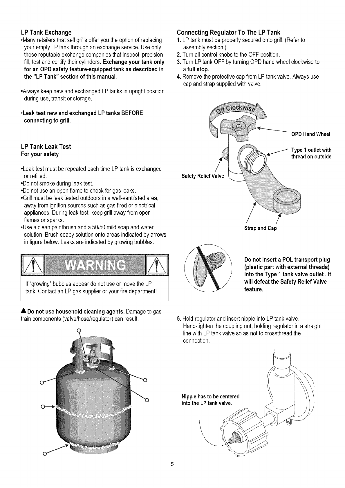
Connecting Regulator To The LP Tank
1. LP tank must be properly secured onto grill. (Refer to
assembly section.)
2. Turn all control knobs to the OFF position.
3. Turn LP tank OFF by turning OPD hand wheel clockwise to
a full stop.
4. Remove the protective cap from LP tank valve. Always use
cap and strap supplied with valve.
OPD HandWheel
._ Type1 outletwith
threadon outside
Safety ReliefValve
/
Strap and Cap
If "growing" bubbles appear do not use or move the LP
tank. Contact an LP gas supplier or your fire department!
Do not insert a POL transport plug
(plastic part with external threads)
into the Type 1 tank valve outlet. It
will defeat the Safety Relief Valve
feature.
• Do not use household cleaning agents. Damage to gas
train components (valve/hose/regulator) can result. 5. Hold regulator and insert nipple into LP tank valve.
Hand-tighten the coupling nut, holding regulator in a straight
linewith LP tank valve so as not to crossthread the
connection.
Nipplehasto be centered
into the LPtank valve.

Holdcouplingnut and regulator
as shownfor properconnection
to LPtankvalve.
6. Turn the coupling nut clockwise and tighten to a full stop.
The regulator will seat on the back-check feature in the LP
tank valve, resulting in some resistance. An additional
one-half to three-quarters turn is required to complete
the connection. Tighten by hand only - do not use tools.
Leak Testing Valves, Hose and Regulator
1.Turnall grillcontrolknobsto OFF.
2. Be sure regulator is tightly connected to LP tank.
.
Completely open LP tank valve by turning OPD hand wheel
counterclockwise. If you hear a rushing sound, turn gas off
immediately. There is a major leak at the connection.
Correct before proceeding by calling Sears for
replacement parts at 1-800-4-MY-HOME®.
4. Brush soapy solution onto areas where bubbles are shown
in picture below:
• Neverremovethreaded
orificeat endof valve.
NOTE:
If you cannot complete the connection, disconnect regulator
and repeat steps 5 and 6. If you are still unable to complete the
connection, do not use this regulatort Call 1-800-482-0131
for assistance.
• Do not insert any tool or foreign object into the valve
outlet or safety relief valve. You may damage the valve
and cause a leak. Leaking propane may result in
explosion,fire, severe personal injury, or death.
• Outdoor gas appliance is not intended to be installed
in or on a boat.
• Outdoor gas appliance is not intended to be installed
in or on an RV.
• Never attempt to attach this grill to the self-contained
LP gas system of a camper trailer or motor home.
• Do not use grill until leak-tested.
• If a leak is detected at any time, STOP and call the
fire department.
• If you cannot stop a gas leak, immediately close
LPcylinder valve and call LP gas supplier or your fire
department!
5. If "growing" bubbles appear, there is a leak. Close LP tank
valve immediately and retighten connections. If leaks
cannot be stopped do not try to repair. Call Sears for
replacement parts at 1-800-4-MY-HOME®.
6. Always close LP tank valve after performing leak test by
turning hand wheel clockwise.
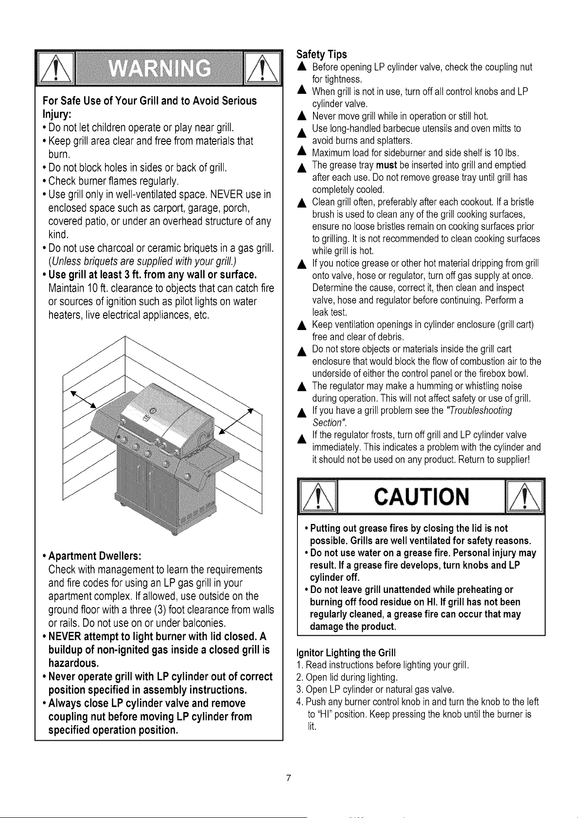
For Safe Use of Your Grill and to Avoid Serious
Injury:
• Do not let children operate or play near grill.
• Keep grill area clear and free from materials that
burn.
• Do not block holes in sides or back of grill.
• Check burnerflames regularly.
• Use grill only in well-ventilated space. NEVER use in
enclosed space such as carport, garage, porch,
covered patio, or under an overhead structure of any
kind.
• Do not use charcoal or ceramic briquets in a gas grill.
(Unless briquets are supplied with your grill.)
• Use grill at least 3 ft. from any wall or surface.
Maintain 10 ft. clearance to objects that can catch fire
or sources of ignition such as pilot lights on water
heaters, live electrical appliances, etc.
• Apartment Dwellers:
Check with management to learn the requirements
and fire codes for using an LP gas grill in your
apartment complex. If allowed, use outside on the
ground floor with a three (3) foot clearance from walls
or rails. Do not use on or under balconies.
° NEVER attempt to light burner with lid closed. A
buildup of non-ignited gas inside a closed grill is
hazardous.
• Never operate grill with LP cylinder out of correct
position specified in assembly instructions.
• Always close LP cylinder valve and remove
coupling nut before moving LP cylinder from
specified operation position.
Safety Tips
• Before opening LP cylinder valve, check the coupling nut
for tightness.
• When grill is not in use, turn off all control knobs and LP
cylinder valve.
• Never move grill while in operation or still hot.
• Use long-handled barbecue utensils and oven mitts to
avoid burns and splatters.
• Maximum load for sideburner and side shelf is 10 Ibs.
• The grease tray must be inserted into grill and emptied
after each use. Do not remove grease tray until grill has
completely cooled.
• Clean grill often, preferably after each cookout. If a bristle
brush is used to clean any of the grill cooking surfaces,
ensure no loose bristles remain on cooking surfaces prior
to grilling. It is not recommended to clean cooking surfaces
while grill is hot.
• Ifyou notice grease or other hot material dripping from grill
onto valve, hose or regulator, turn off gas supply at once.
Determine the cause, correct it, then clean and inspect
valve, hose and regulator before continuing. Perform a
leak test.
• Keep ventilation openings in cylinder enclosure (grill cart)
free and clear of debris.
• Do not store objects or materials inside the grill cart
enclosure that would block the flow of combustion air to the
underside of either the control panel or the firebox bowl.
• The regulator may make a humming or whistling noise
during operation. This will not affect safety or use of grill.
• Ifyou have a grill problem see the "Troubleshooting
Section".
• If the regulator frosts, turn off grill and LP cylinder valve
immediately. This indicates a problem with the cylinder and
it should not be used on any product. Return to supplier!
CAUTION
• Putting out grease fires by closing the lid is not
possible. Grills are well ventilated for safety reasons.
• Do not use water on a grease fire. Personal injury may
result. If a grease fire develops, turn knobs and LP
cylinder off.
• Do not leave grill unattended while preheating or
burning off food residue on HI. If grill has not been
regularly cleaned, a grease fire can occur that may
damage the product.
Ignitor Lighting the Grill
1. Read instructions before lighting your grill.
2. Open lid during lighting.
3. Open LP cylinder or natural gas valve.
4. Push any burner control knob in and turn the knob to the left
to "HI" position. Keep pressing the knob until the burner is
lit.
5.Ifignitiondoesnotoccurin5seconds,turntheburner
controloff,wait5minutesforgastoclearaway,andrepeat
thelightingprocedure.
6.Tolightotherburners,repeatstep4.
NOTE:Ifignitordoesnotwork,followMatchLighting
instructions.
Turn controls and gas source or tank OFF when
not in use.
If ignitiondoesnot occurin5 seconds,turnthe burner
controloff,wait5 minutes,and repeatthe lighting
procedure.If the burner does not ignite with
the valve open, gas will continue to flow out of the
burner and could accidently ignite with risk of
injury.
Match-Lighting
• Do not lean over grill while lighting.
1. Open lid during lighting.
2. Place match into match holder (hanging from side of cart).
Light match, place into the firebox.
3. Push in and turn right knob to HIGH position. Be sure burner
lights and stays Iit.
4. Light other burners by pushing knob in and turning to HI
position.
Sideburner Match Lighting
1. Open sideburner lid. Turn on gas at LP cylinder.
2. Place Iit match near burner.
&Turn sideburner knob to HI. Be sure burner lights and
stays Iit.
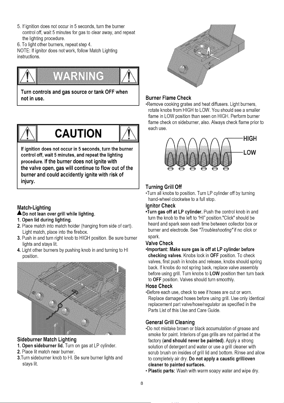
Burner Flame Check
,Remove cooking grates and heat diffusers. Light burners,
rotate knobs from HIGH to LOW. You should see a smaller
flame in LOW position than seen on HIGH. Perform burner
flame check on sideburner, also. Always check flame prior to
each use.
Turning GrillOff
•Turn all knobs to position. Turn LP cylinder off by turning
hand-wheel clockwise to a full stop.
Ignitor Check
•Turn gas off at LP cylinder. Push the control knob in and
turn the knob to the left to "HI" position."Click" should be
heard and spark seen each time between collector box or
burner and electrode. See "Troubleshooting" if no click or
spark.
Valve Check
•Important: Make sure gas is off at LP cylinder before
checking valves. Knobs lock in OFF position. To check
valves, first push in knobs and release, knobs should spring
back. If knobs do not spring back, replace valve assembly
before using grill. Turn knobs to LOW position then turn back
to OFF position. Valves should turn smoothly.
Hose Check
•Before each use, check to see if hoses are cut or worn.
Replace damaged hoses before using grill. Use only identical
replacement part valve/hose/regulator as specified in the
Parts List of this Use and Care Guide.
General Grill Cleaning
•Do not mistake brown or black accumulation of grease and
smoke for paint. Interiors of gas grills are not painted at the
factory (and should never be painted). Apply a strong
solution of detergent and water or use a grill cleaner with
scrub brush on insides of grill lid and bottom. Rinse and allow
to completely air dry. Do not apply a caustic grill/oven
cleaner to painted surfaces.
• Plastic parts: Wash with warm soapy water and wipe dry.
Donotusecitrisot,abrasivecleaners,degreasersora
concentratedgrillcleaneronplasticparts.Damagetoand
failureofpartscanresult.
•Porcelainsurfaces:Becauseofglass-likecomposition,most
residuecanbewipedawaywithbakingsoda/watersolutionor
speciallyformulatedcleaner.Usenonabrasivescouring
powderforstubbornstains.
*Painted surfaces: Wash with mild detergent or nonabrasive
cleaner and warm soapy water. Wipe dry with a soft
nonabrasive cloth.
•Stainless steel surfaces: To maintain your grill's high quality
appearance, wash with mild detergent and warm soapy water
and wipe dry with a soft cloth after each use. Baked-on
grease deposits may require the use of an abrasive plastic
cleaning pad. Use only in direction of brushed finish to avoid
damage. Do not use abrasive pad on areas with graphics.
• Cooking surfaces: If a bristle brush is used to clean any of
the grill cooking surfaces, ensure no loose bristles remain on
cooking surfaces prior to grilling. It is not recommended to
clean cooking surfaces while grill is hot.
Storing Your Grill
•Clean cooking grates.
•Store in dry location.
•When LP cylinder is connected to grill, store outdoors in a
welIventiIatedspace and out of reach of children.
•Cover grill if stored outdoors. Choose from a variety of grill
covers offered by manufacturer.
•Store grill indoors ONLY if LP cylinder is turned off and
disconnected, removed from grill and stored outdoors.
•When removing grill from storage, follow "Cleaning the Burner
Assembly' instructions before starting grill.
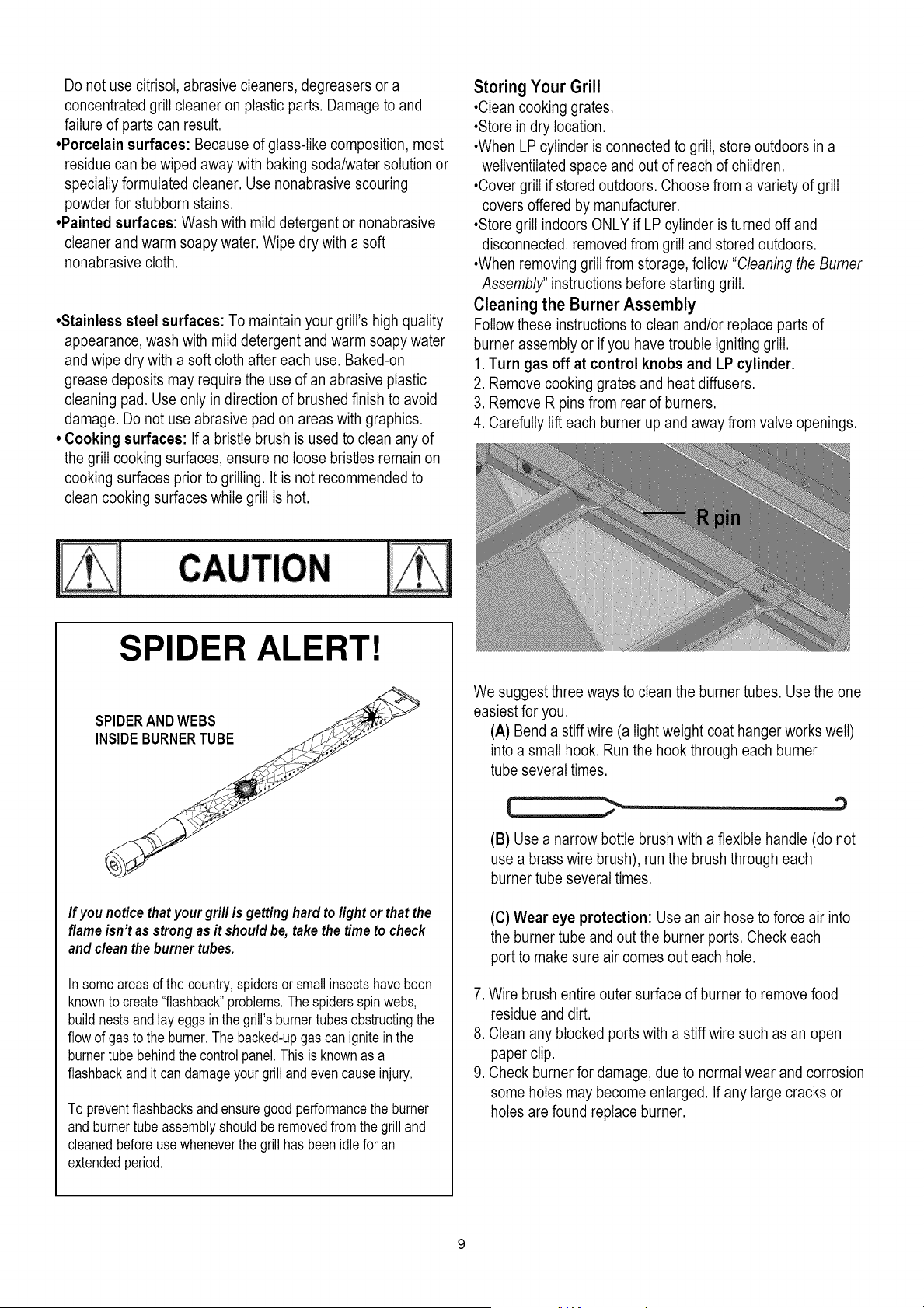
Cleaning the Burner Assembly
Follow these instructions to clean and/or replace parts of
burner assembly or if you have trouble igniting grill.
1. Turn gas off at control knobs and LP cylinder.
2. Remove cooking grates and heat diffusers.
3. Remove R pins from rear of burners.
4. Carefully lift each burner up and away from valve openings.
SPIDER ALERT!
SPIDERANDWEBS
NSDE BURNERTUBE , -
If you notice that your grill is getting hard to light or that the
flame isn't as strong as it should be, take the time to check
and clean the burner tubes.
In someareasof the country,spidersor smallinsectshavebeen
knownto create"flashback"problems.Thespidersspinwebs,
buildnestsand lay eggsin thegrill'sburnertubesobstructingthe
flowof gasto the burner.The backed-upgas canignitein the
burnertube behindthecontrolpanel.Thisis knownas a
flashbackandit can damageyourgrill andevencauseinjury.
To preventflashbacksand ensuregoodperformancethe burner
and burnertube assemblyshouldberemovedfrom the grilland
cleanedbeforeusewheneverthe grill has beenidlefor an
extendedperiod.
We suggest three ways to clean the burner tubes. Use the one
easiest for you.
(A) Bend a stiff wire (a light weight coat hanger works well)
into a small hook. Run the hook through each burner
tube several times.
J
'3
(B) Use a narrow bottle brush with a flexible handle (do not
use a brass wire brush), run the brush through each
burner tube several times.
(C) Wear eye protection: Use an air hose to force air into
the burner tube and out the burner ports. Check each
port to make sure air comes out each hole.
7. Wire brush entire outer surface of burner to remove food
residue and dirt.
8. Clean any blocked ports with a stiffwire such as an open
paper clip.
9. Check burner for damage, due to normal wear and corrosion
some holes may become enlarged. If any large cracks or
holes are found replace burner.
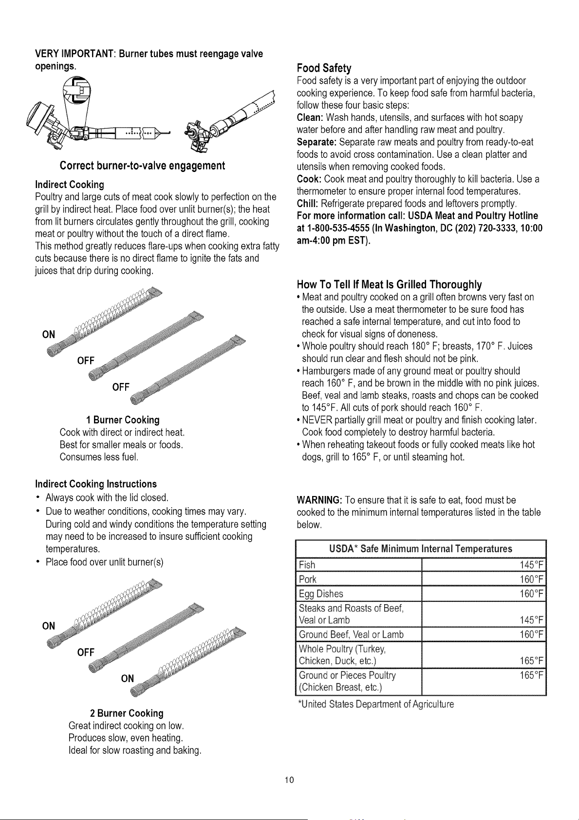
VERY IMPORTANT: Burner tubes must reengage valve
openings.
Correct burner-to-valve engagement
Indirect Cooking
Poultry and large cuts of meat cook slowly to perfection on the
grill by indirect heat. Place food over unlit burner(s); the heat
from lit burners circulates gently throughout the grill, cooking
meat or poultry without the touch of a direct flame.
This method greatly reduces flare-ups when cooking extra fatty
cuts because there is no direct flame to ignite the fats and
juices that drip during cooking.
1 Burner Cooking
Cook with direct or indirect heat.
Best for smaller meals or foods.
Consumes less fuel.
Indirect Cooking Instructions
• Always cook with the lid closed.
• Due to weather conditions, cooking times may vary.
During cold and windy conditions the temperature setting
may need to be increased to insure sufficient cooking
temperatures.
• Place food over unlit burner(s)
2 Burner Cooking
Great indirect cooking on low.
Produces slow, even heating.
Ideal for slow roasting and baking.
Food Safety
Food safety is a very important part of enjoying the outdoor
cooking experience. To keep food safe from harmful bacteria,
follow these four basic steps:
Clean: Wash hands, utensils, and surfaces with hot soapy
water before and after handling raw meat and poultry.
Separate: Separate raw meats and poultry from ready-to-eat
foods to avoid cross contamination. Use a clean platter and
utensils when removing cooked foods.
Cook: Cook meat and poultry thoroughly to kill bacteria. Use a
thermometer to ensure proper internal food temperatures.
Chill: Refrigerate prepared foods and leftovers promptly.
For more information call: USDA Meat and Poultry Hotline
at 1-800-535-4555 (In Washington, DC (202) 720-3333, 10:00
am-4:00 pm EST).
How To Tell If Meat Is Grilled Thoroughly
• Meat and poultry cooked on a grill often browns very fast on
the outside. Use a meat thermometer to be sure food has
reached a safe internal temperature, and cut into food to
check for visual signs of aloneness.
• Whole poultry should reach 180° F; breasts, 170° F. Juices
should run clear and flesh should not be pink.
• Hamburgers made of any ground meat or poultry should
reach 160° F, and be brown in the middle with no pink juices.
Beef, veal and lamb steaks, roasts and chops can be cooked
to 145°F. All cuts of pork should reach 160° F.
• NEVER partially grill meat or poultry and finish cooking later.
Cook food completely to destroy harmful bacteria.
• When reheating takeout foods or fully cooked meats like hot
dogs, grill to 165° F, or until steaming hot.
WARNING: To ensure that it is safe to eat, food must be
cooked to the minimum internal temperatures listed in the table
below.
USDA* Safe Minimum Internal Temperatures
Fish 145°F
Pork 160°F
Egg Dishes 160°F
Steaks and Roasts of Beef,
Vealor Lamb 145°F
Ground Beef, Veal or Lamb 160°F
Whole Poultry (Turkey,
Chicken, Duck, etc.) 165°F
Ground or Pieces Poultry 165°F
(Chicken Breast, etc.)
*United States Departmentof Agriculture
10
To purchase Natural Gas Conversion Parts call Sears at
1-800-4-MY-HOME®
Natural gas conversion kit
(Manufacturer Part No.: L3018S-KIT)
Your grill can be converted to natural gas with this
conversion kit by a qualified gas technician only. In order
to convert this grill the technician will need this
conversion kit.
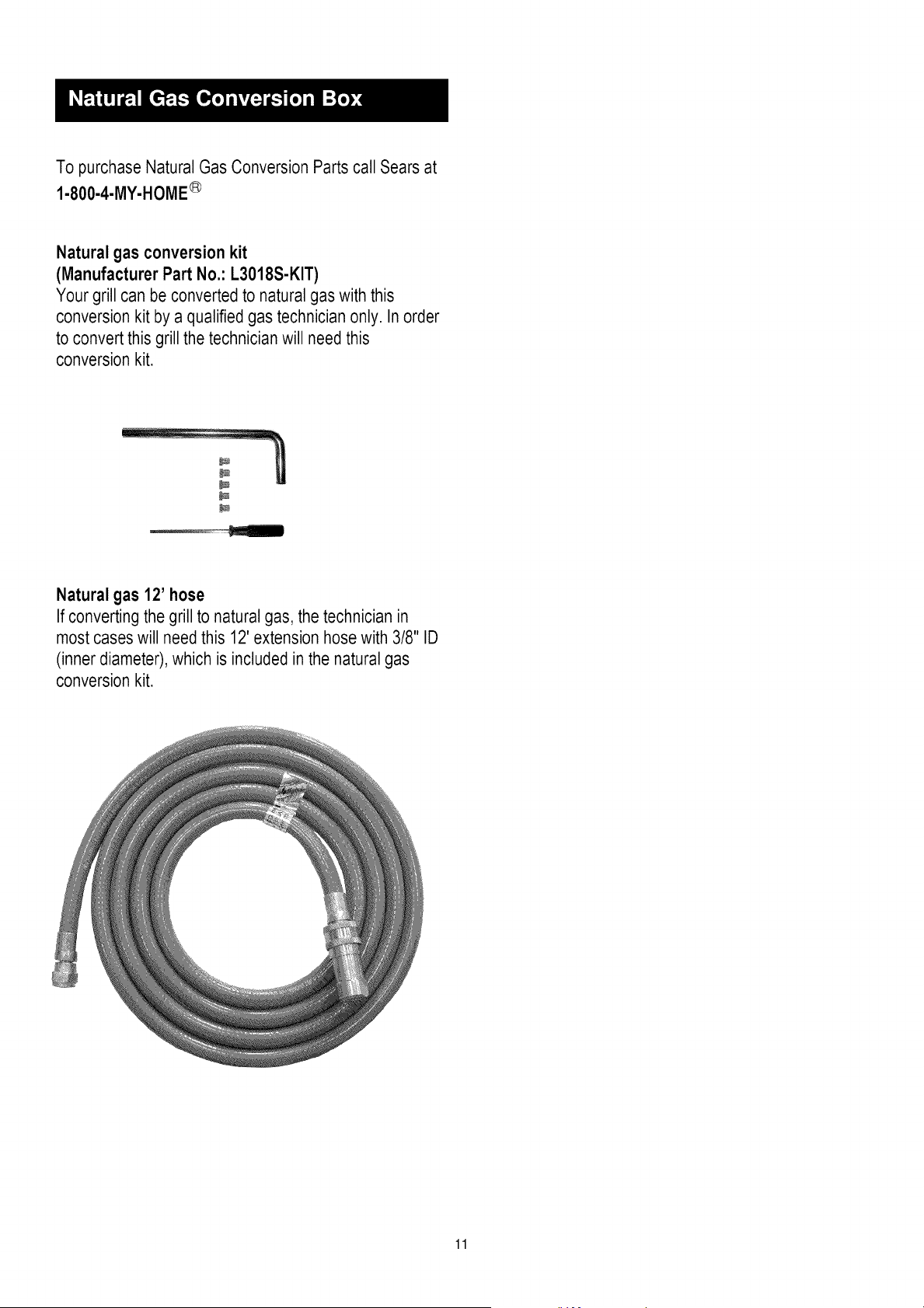
Natural gas 12' hose
If converting the grill to natural gas, the technician in
most cases will need this 12' extension hose with 3/8" ID
(inner diameter),which is included in the natural gas
conversion kit.
11
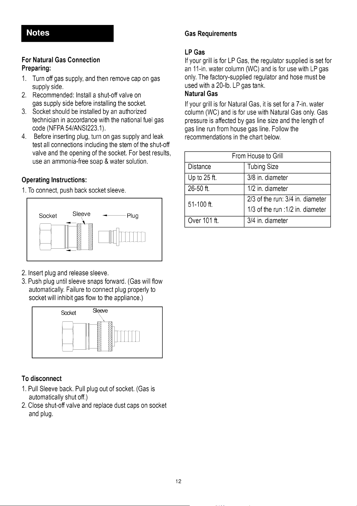
Gas Requirements
For Natural Gas Connection
Preparing:
1. Turn off gas supply, and then remove cap on gas
supply side.
2. Recommended: Install a shut-off valve on
gas supply side before installing the socket.
3. Socket should be installed by an authorized
technician in accordance with the national fuel gas
code (NFPA54/ANSI223.1).
4. Before inserting plug, turn on gas supply and leak
test all connections including the stem of the shut-off
valve and the opening of the socket. For best results,
use an ammonia-free soap & water solution.
Operating Instructions:
1. To connect, push back socket sleeve.
Socket Sleeve = Plug
\
LP Gas
If your grill is for LP Gas, the regulator supplied is set for
an 11-in.water column (WC) and is for use with LP gas
only. The factory-supplied regulator and hose must be
used with a 20-lb. LP gas tank.
Natural Gas
If your grill is for Natural Gas, it is set for a 7-in. water
column (WC) and is for use with Natural Gas only. Gas
pressure is affected by gas line size and the length of
gas line run from house gas line. Follow the
recommendations in the chart below.
From House to Grill
Distance Tubing Size
Up to 25 ft. 3/8 in. diameter
26-50 ft. 1/2 in. diameter
2/3 of the run: 3/4 in. diameter
51-100 ft.
1/3of the run :1/2 in. diameter
Over 101 ft. 3/4 in. diameter
2. Insert plug and release sleeve.
3. Push plug until sleeve snaps forward. (Gas will flow
automatically.Failure to connect plug properly to
socket will inhibit gas flow to the appliance.)
Socket Sleeve
\\\
To disconnect
1. Pull Sleeve back. Pull plug out of socket. (Gas is
automatically shut off.)
2. Close shut-off valve and replacedust caps on socket
and plug.
12
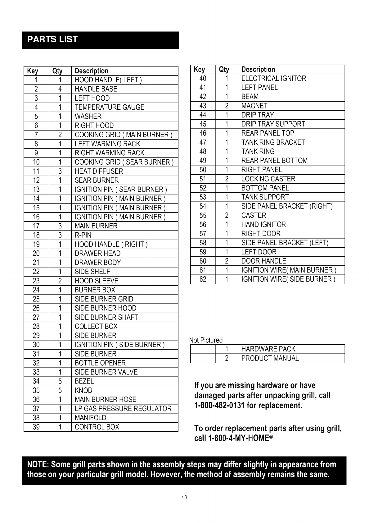
Key Qty Description
1 1 HOOD HANDLE( LEFT )
2 4 HANDLE BASE
3 1 LEFT HOOD
4 1 TEMPERATURE GAUGE
5 1 WASHER
6 1 RIGHT HOOD
7 2 COOKING GRID ( MAIN BURNER )
8 1 LEFT WARMING RACK
9 1 RIGHT WARMING RACK
10 1 COOKING GRID ( SEAR BURNER )
11 3 HEAT DIFFUSER
12 1 SEAR BURNER
13 1 IGNITION PIN ( SEAR BURNER )
14 1 IGNITION PIN ( MAIN BURNER )
15 1 IGNITION PIN ( MAIN BURNER )
16 1 IGNITION PIN ( MAIN BURNER )
17 3 MAIN BURNER
18 3 R-PIN
19 1 HOOD HANDLE ( RIGHT )
20 1 DRAWER HEAD
21 1 DRAWER BODY
22 1 SIDE SHELF
23 2 HOOD SLEEVE
24 1 BURNER BOX
25 1 SIDE BURNER GRID
26 1 SIDE BURNER HOOD
27 1 SIDE BURNER SHAFT
28 1 COLLECT BOX
29 1 SIDE BURNER
30 1 IGNITION PIN ( SIDE BURNER )
31 1 SIDE BURNER
32 1 BOTTLEOPENER
33 1 SIDE BURNER VALVE
34 5 BEZEL
35 5 KNOB
36 1 MAIN BURNER HOSE
37 1 LP GAS PRESSURE REGULATOR
38 1 MANIFOLD
39 1 CONTROL BOX
Key Qty Description
40 1 ELECTRICAL IGNITOR
41 1 LEFT PANEL
42 1 BEAM
43 2 MAGNET
44 1 DRIPTRAY
45 1 DRIPTRAY SUPPORT
46 1 REAR PANEL TOP
47 1 TANK RING BRACKET
48 1 TANK RING
49 1 REAR PANEL BOTTOM
50 1 RIGHT PANEL
51 2 LOCKINGCASTER
52 1 BOTTOMPANEL
53 1 TANK SUPPORT
54 1 SIDE PANEL BRACKET (RIGHT)
55 2 CASTER
56 1 HAND IGNITOR
57 1 RIGHT DOOR
58 1 SIDE PANEL BRACKET (LEFT)
59 1 LEFT DOOR
60 2 DOOR HANDLE
61 1 IGNITIONWIRE( MAIN BURNER )
62 1 IGNITIONWIRE( SIDE BURNER )
Not Pictured
1
2
HARDWARE PACK
PRODUCT MANUAL
If you are missing hardwareor have
damagedparts after unpackinggrill, call
1-800-482-0131for replacement.
To order replacement parts after using grill,
call 1-800-4-MY-HOME®
13
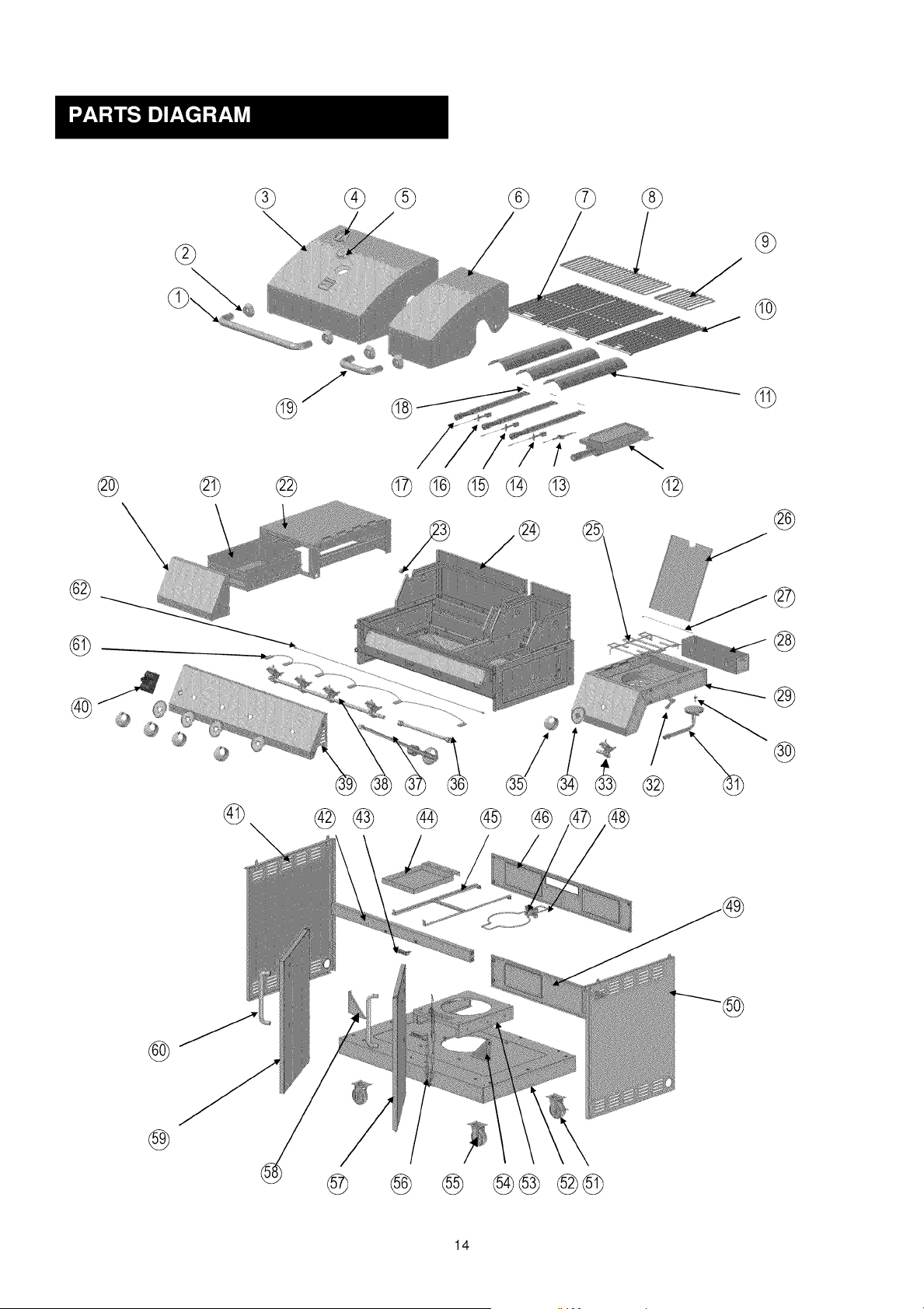
@
®
®
@
@ © ® @®®®_ ®
®
@
@
®
© @©
®
®
@
@ _ @
14
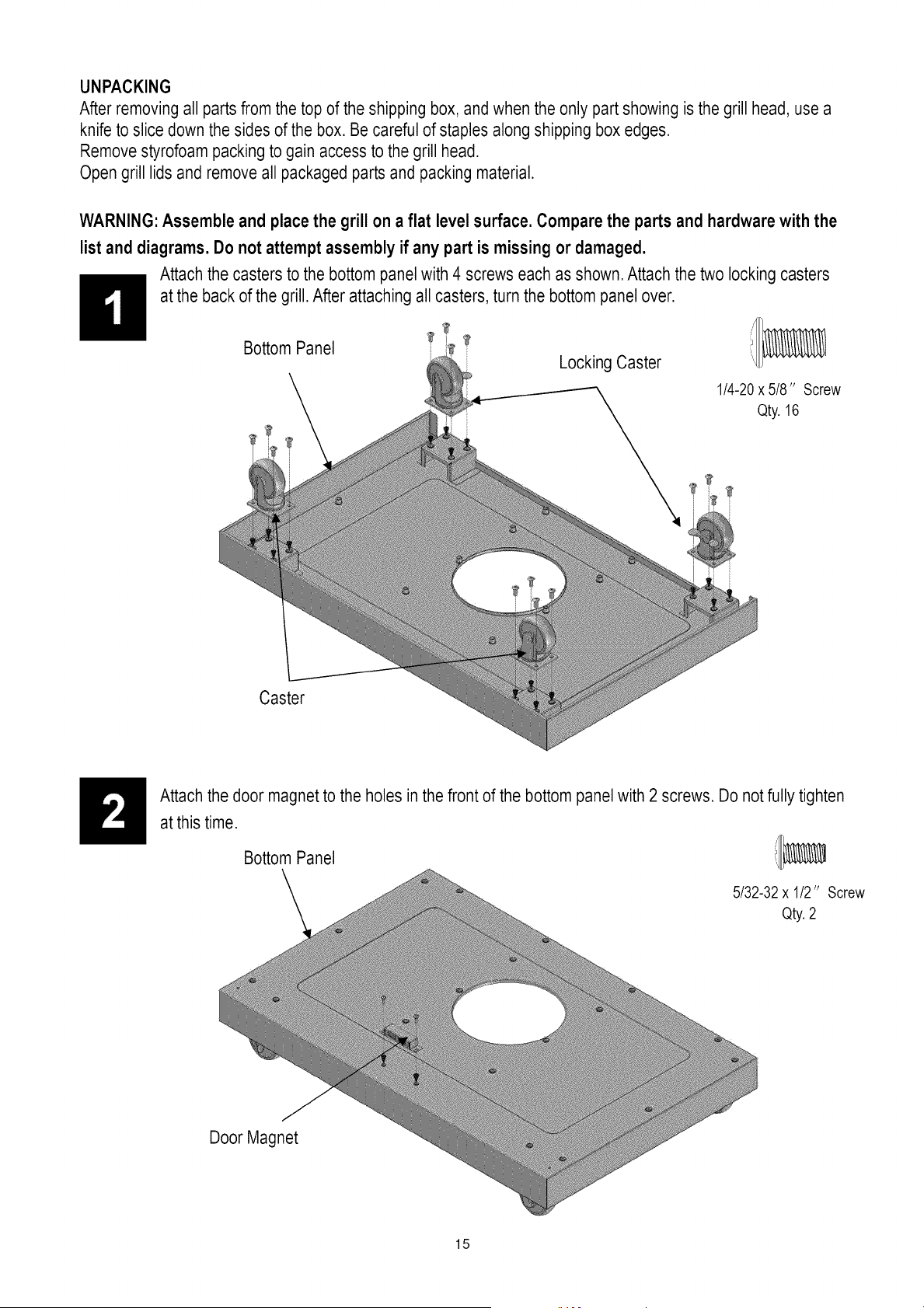
UNPACKING
After removing all parts from the top of the shipping box, and when the only part showing is the grill head, use a
knife to slice down the sides of the box. Be careful of staples along shipping box edges.
Remove styrofoam packing to gain access to the grill head.
Open grill lids and remove all packaged parts and packing material.
WARNING: Assemble and place the grill on a flat level surface. Compare the parts and hardwarewith the
list and diagrams. Do not attempt assembly if any part is missing or damaged.
Attach the casters to the bottom panel with 4 screws each as shown. Attach the two locking casters
at the back of the grill. After attaching all casters, turn the bottom panel over.
Bottom Panel
Locking Caster
1/4-20x 5/8" Screw
Qty. 16
Caster
Attach the door magnet to the holes in the front of the bottom panel with 2 screws. Do not fully tighten
at this time.
Bottom Panel i/_
5/32-32x 1/2" Screw
Qty.2
Door Magnet
15
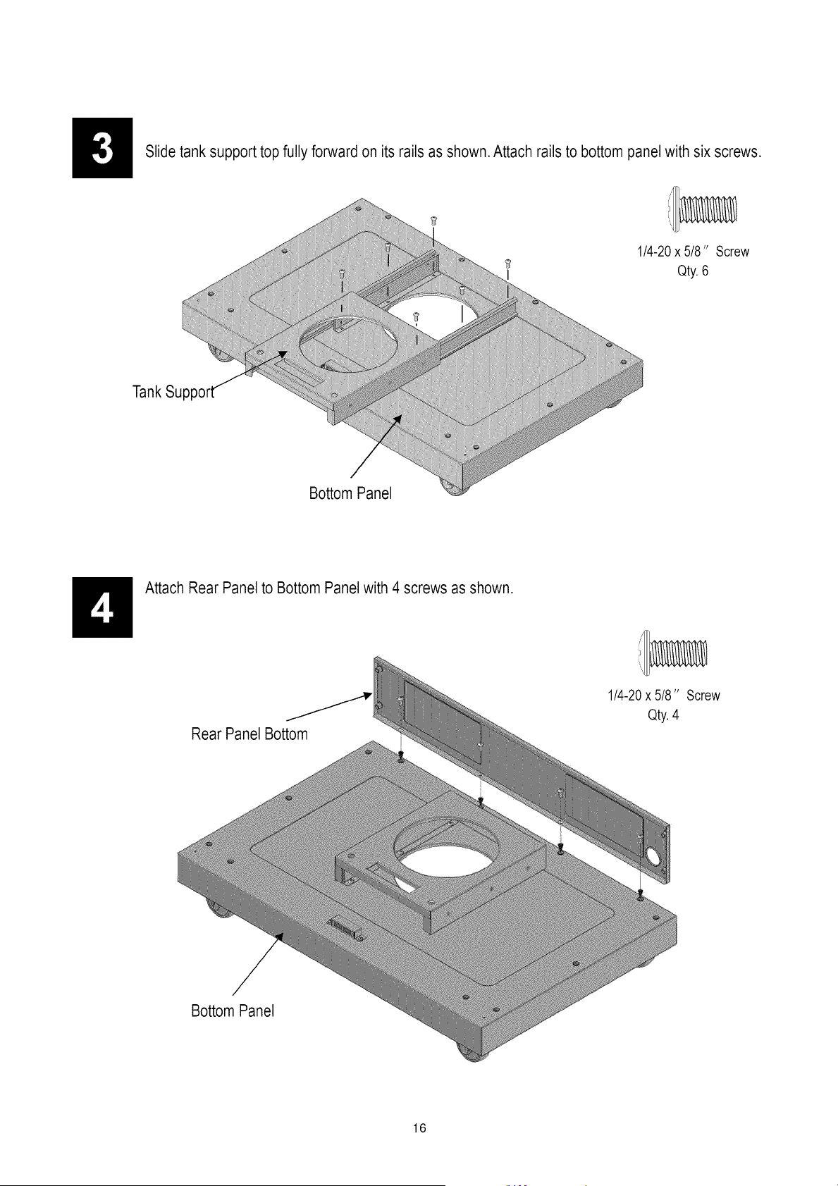
Slide tank support top fully forward on its rails as shown. Attach rails to bottom panel with six screws.
1/4-20 x 5/8" Screw
Qty.6
TankSu
Bottom Panel
Attach Rear Panelto Bottom Panel with 4 screws as shown.
y 1/4-20x 5/8" Screw
Qty.4
Rear Panel Bottom
Bottom Panel
16
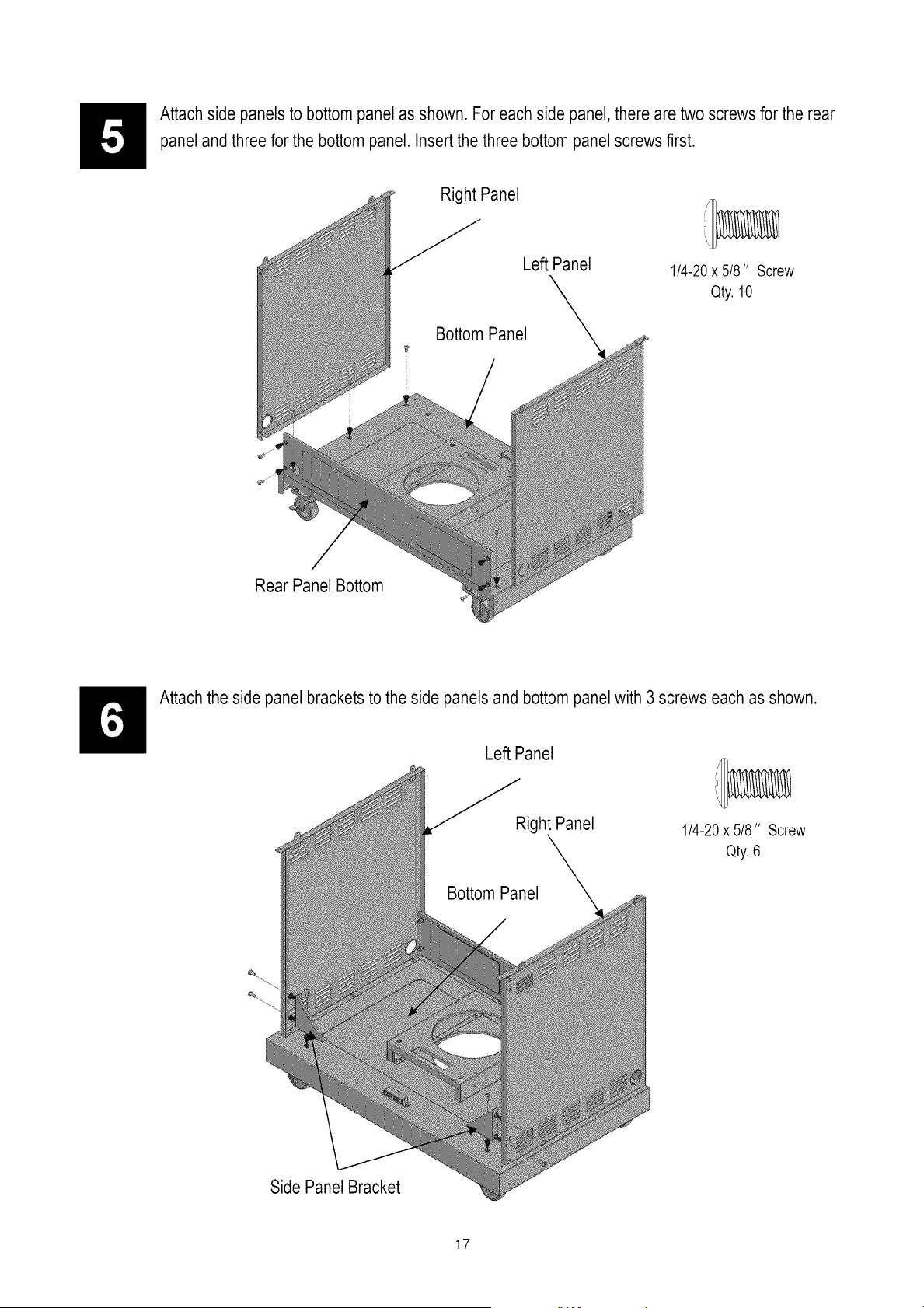
Attach side panels to bottom panel as shown. For each side panel, there are two screws for the rear
panel and three for the bottom panel. Insert the three bottom panel screws first.
Rear Panel Bottom
Right Panel
Left Panel
1/4-20x 5/8" Screw
Qty. 10
Attach the side panel brackets to the side panels and bottom panel with 3 screws each as shown.
Left Panel
Side Panel Bracket
Right Panel
1/4-20x 5/8" Screw
Qty. 6
17
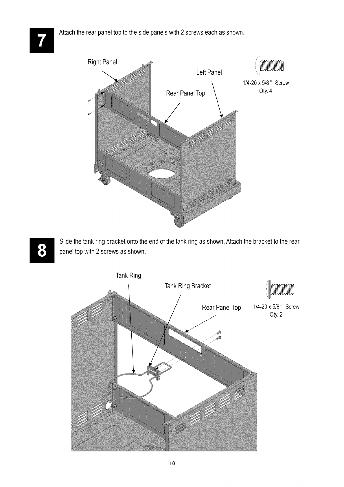
Attach the rear panel top to the side panels with 2 screws each as shown.
Right Panel
Le_ Panel
Rear Panel Top
1/4-20x 5/8"
Qty.4
Screw
Slide the tank ring bracket onto the end of the tank ring as shown. Attach the bracket to the rear
panel top with 2 screws as shown.
Tank Ring
Tank Ring Bracket
Rear Panel Top 1/4-20x 5/8" Screw
__ Qty. 2
18
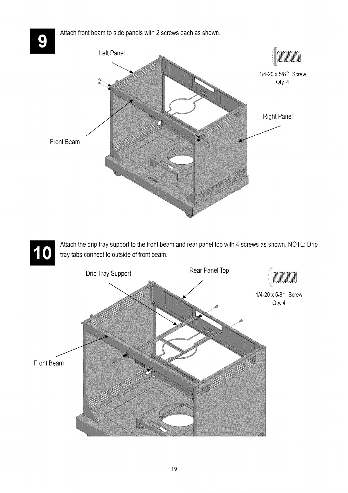
Attach front beam to side panels with 2 screws each as shown.
Left Panel
1/4-20x 5/8" Screw
Qty.4
Right Panel
Front Beam
Attach the drip tray support to the front beam and rear panel top with 4 screws as shown. NOTE: Drip
tray tabs connect to outside of front beam.
Drip Tray Support
Rear Panel Top
1/4-20x 5/8" Screw
Qty.4
Front Beam
19
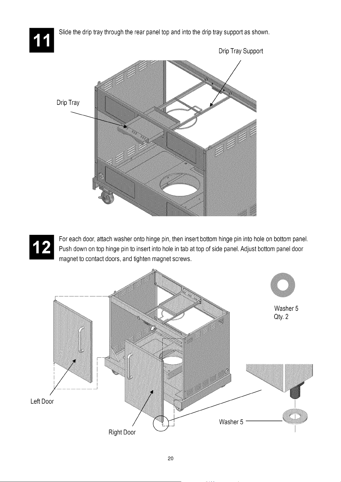
Slide the drip tray through the rear panel top and into the drip tray support as shown.
Drip Tray Support
Drip Tray
For each door, attach washer onto hinge pin, then insert bottom hinge pin into hole on bottom panel.
Push down on top hinge pin to insert into hole in tab at top of side panel. Adjust bottom panel door
magnet to contact doors, and tighten magnet screws.
Washer 5
Qty. 2
Left Door
Right Door
Washer 5
20
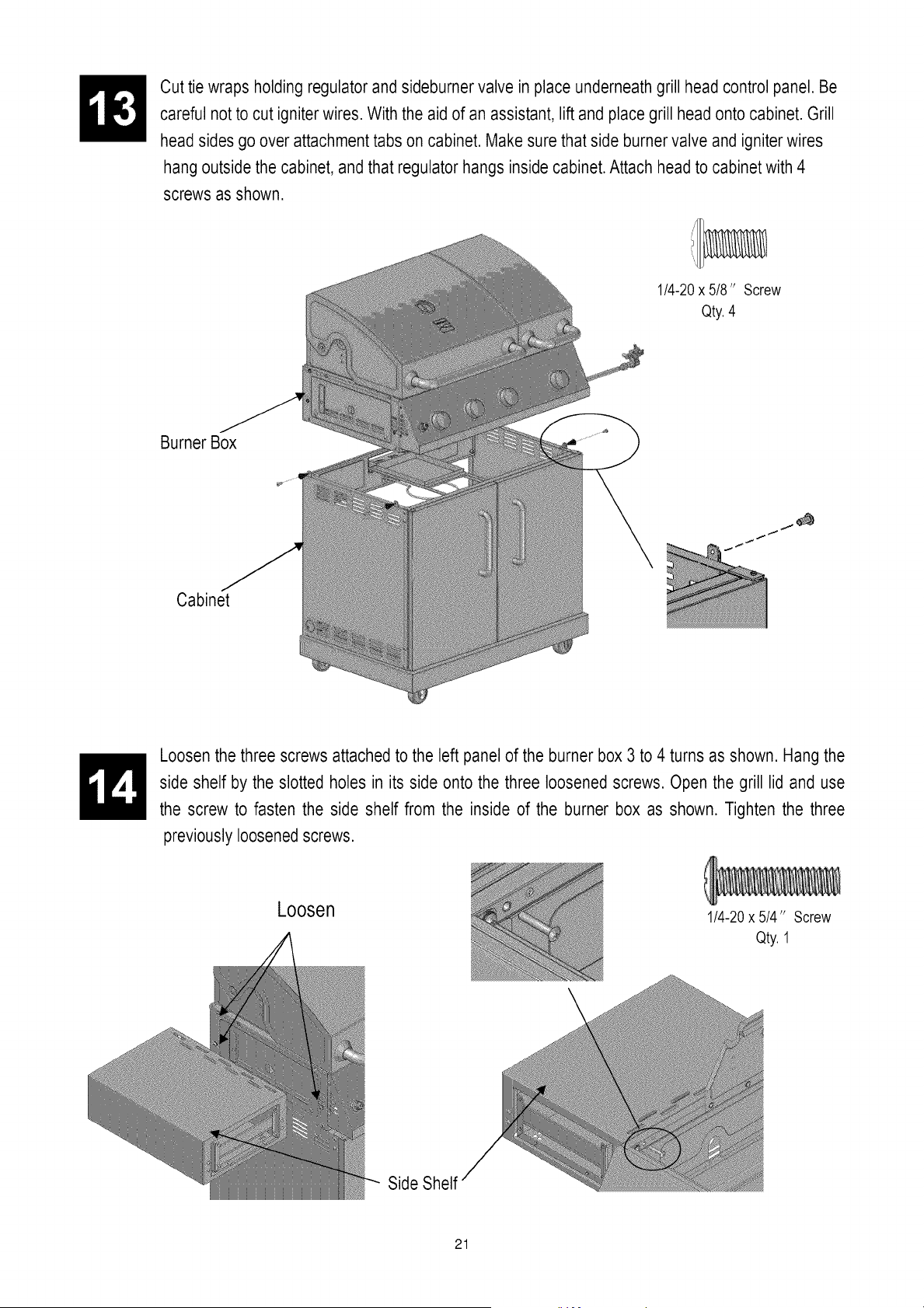
Cut tie wraps holding regulator and sideburner valve in place underneath grill head control panel. Be
careful not to cut igniterwires. With the aid of an assistant, lift and place grill head onto cabinet. Grill
head sides go over attachment tabs on cabinet. Make sure that side burner valve and igniter wires
hang outside the cabinet, and that regulator hangs inside cabinet.Attach head to cabinet with 4
screws as shown.
1/4-20x 5/8" Screw
Qty.4
Burner Box
j_
Cabinet
Loosen the three screws attached to the left panel of the burner box 3 to 4 turns as shown. Hang the
side shelf by the slotted holes in its side onto the three loosened screws. Open the grill lid and use
the screw to fasten the side shelf from the inside of the burner box as shown. Tighten the three
previously loosened screws.
Loosen
1/4-20x 5/4" Screw
Qty. 1
Side Shelf
21
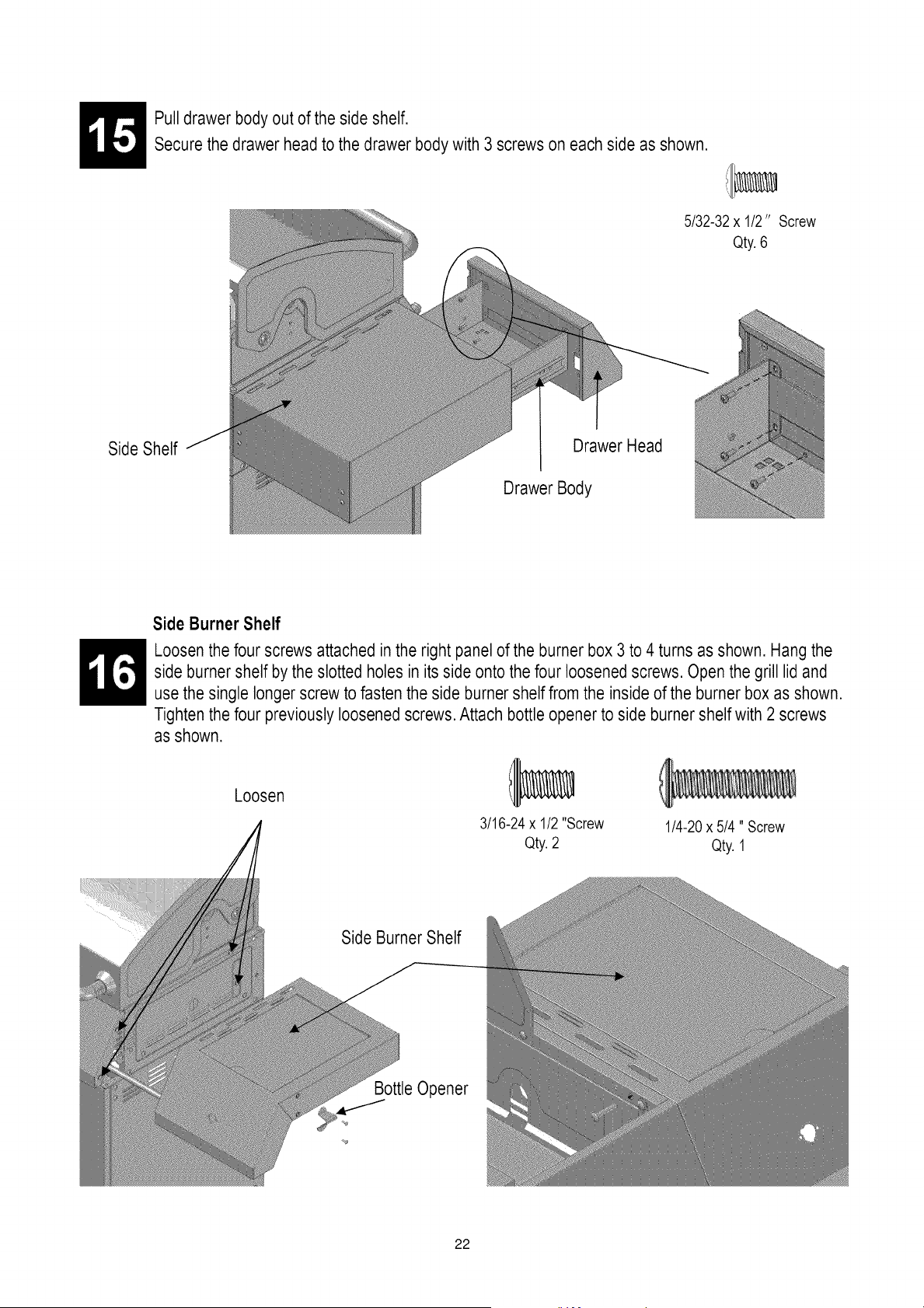
Pull drawer body out of the side shelf.
Secure the drawer head to the drawer body with 3 screws on each side as shown.
5/32-32 x 1/2" Screw
Qty.6
Side Shelf
Drawer Head
Drawer Body
Side Burner Shelf
Loosen the four screws attached inthe right panel of the burner box 3 to 4 turns as shown. Hang the
side burner shelf by the slotted holes in its side onto the four loosened screws. Open the grill lid and
use the single longerscrew to fasten the side burner shelf from the inside of the burner box as shown.
Tighten the four previously loosened screws. Attach bottle opener to side burner shelf with 2 screws
as shown.
Loosen
3/16-24x 1/2"Screw
Qty.2
1/4-20x 5/4" Screw
Qty. 1
Side Burner Shelf
22
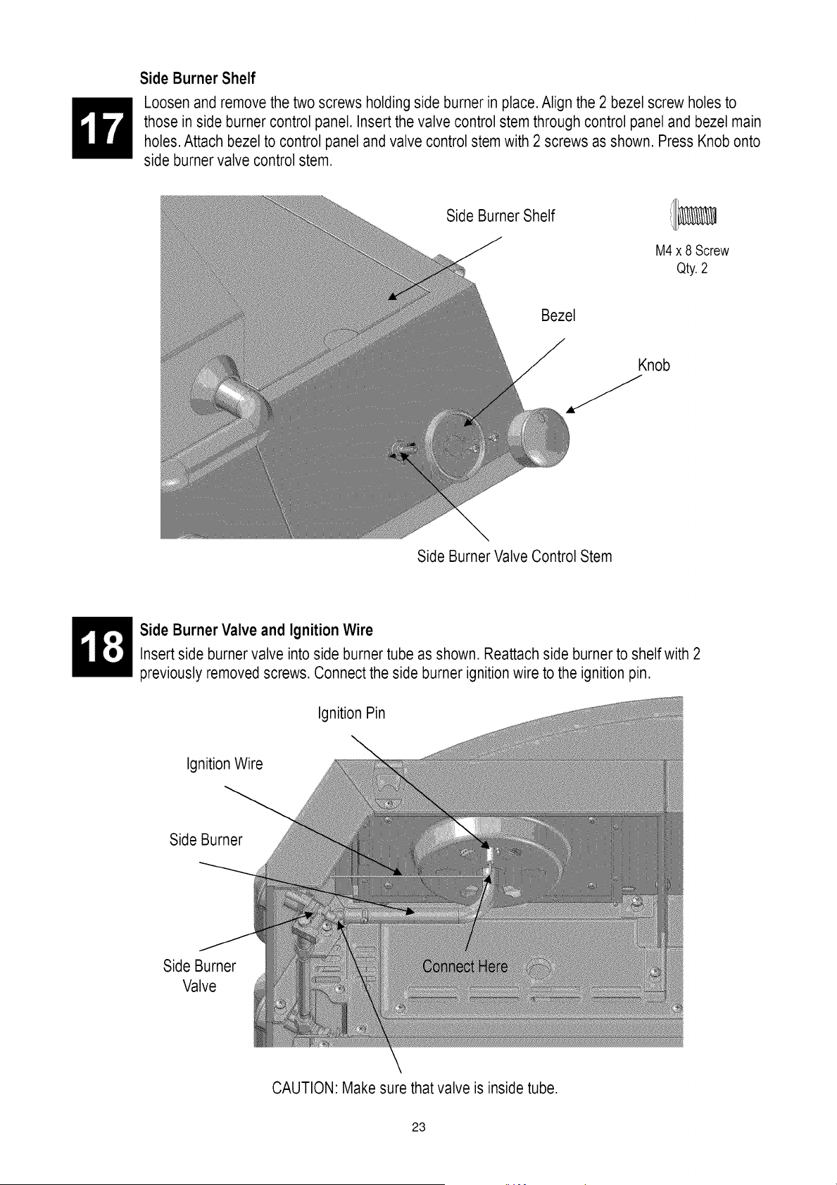
Side Burner Shelf
Loosen and remove the two screws holding side burner in place.Align the 2 bezel screw holes to
those in side burner control panel. Insertthe valve control stem through control panel and bezel main
holes. Attach bezel to control panel and valve control stem with 2 screws as shown. Press Knob onto
side burner valve control stem.
Side Burner Shelf
M4 x 8 Screw
Qty.2
Bezel
Knob
Side Burner Valve Control Stem
Side Burner Valve and Ignition Wire
Insertside burner valve into side burner tube as shown. Reattach side burner to shelf with 2
previously removed screws. Connect the side burner ignition wire to the ignition pin.
Ignition Pin
IgnitionWire
Side Burner
Side Burner
Valve
CAUTION: Make sure that valve is inside tube.
23
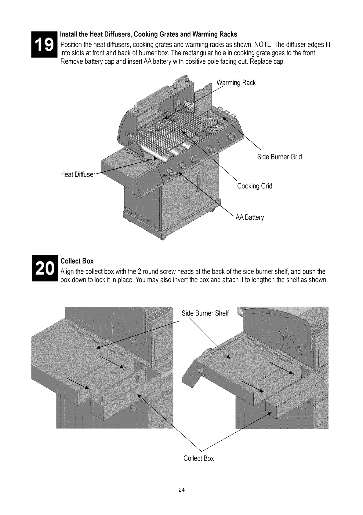
Install the Heat Diffusers, Cooking Grates and Warming Racks
Position the heat diffusers, cooking grates and warming racks as shown. NOTE: The diffuser edges fit
into slots at front and back of burner box. The rectangular hole in cooking grate goes to the front.
Remove battery cap and insertAA battery with positive pole facing out. Replace cap.
Warming Rack
Side Burner Grid
Heat
Cooking Grid
AA Battery
_ ollect Box
Align the collect box with the 2 round screw heads at the back of the side burner shelf, and push the
box down to lock it in place. You may also invert the box and attach it to lengthen the shelf as shown.
Side Burner Shelf
Collect Box
24
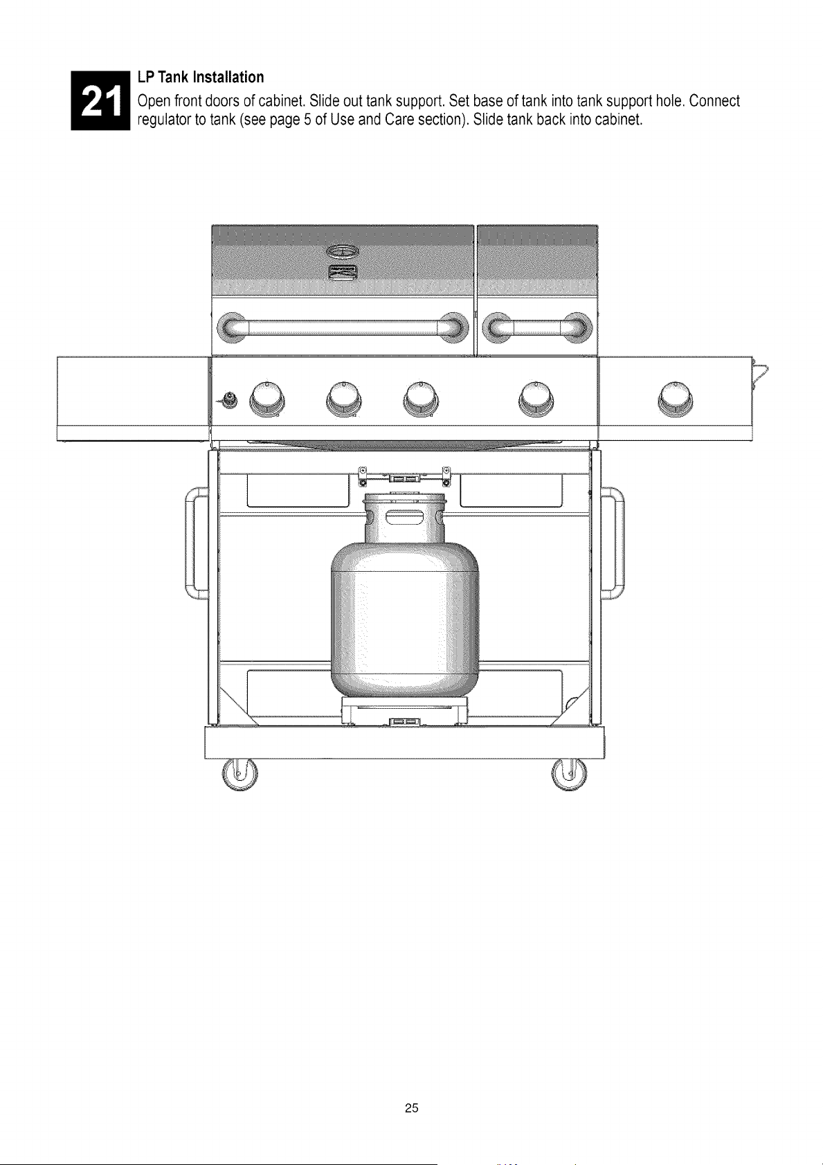
LP Tank Installation
Open front doors of cabinet. Slide out tank support. Set base of tank into tank support hole. Connect
regulator to tank (see page 5 of Use and Care section). Slide tank back into cabinet.
Z
25
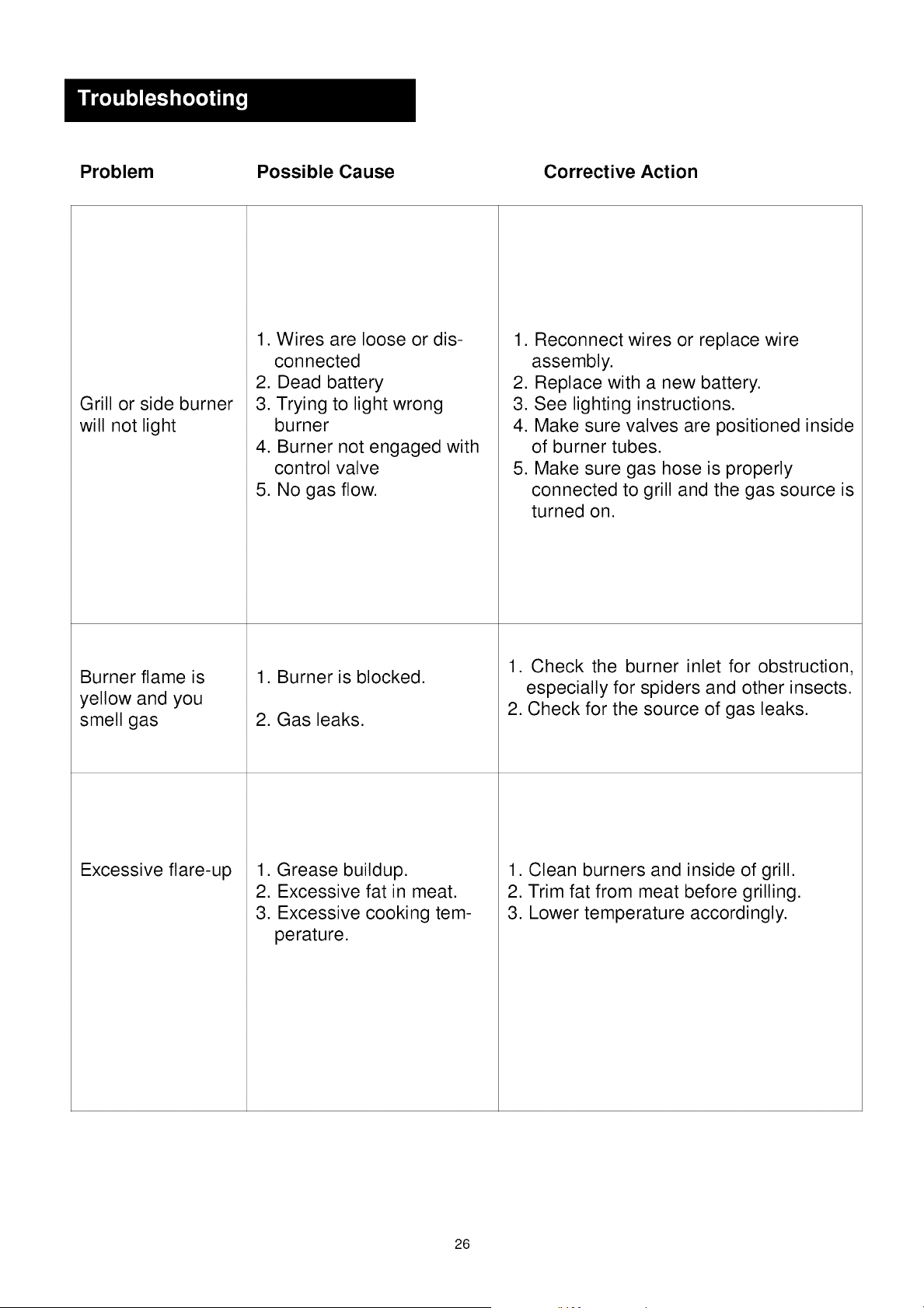
Problem Possible Cause Corrective Action
Grill or side burner
will not light
Burner flame is
yellow and you
smell gas
1. Wires are loose or dis-
connected
2. Dead battery
3. Trying to light wrong
burner
4. Burner not engaged with
control valve
5. No gas flow.
Excessive flare-up
1. Burner is blocked.
2. Gas leaks.
1. Grease buildup.
2. Excessive fat in meat.
3. Excessive cooking tem-
perature.
1. Reconnect wires or replace wire
assembly.
2. Replace with a new battery.
3. See lighting instructions.
4. Make sure valves are positioned inside
of burner tubes.
5. Make sure gas hose is properly
connected to grill and the gas source is
turned on.
1. Check the burner inlet for obstruction,
especially for spiders and other insects.
2. Check for the source of gas leaks.
1. Clean burners and inside of grill.
2. Trim fat from meat before grilling.
3. Lower temperature accordingly.
26
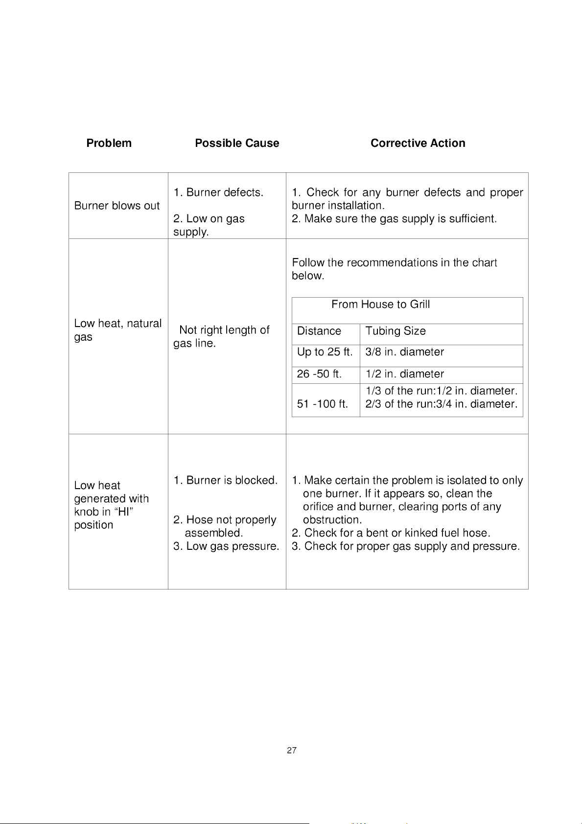
Problem Possible Cause Corrective Action
Burner blows out
1. Burner defects.
2. Low on gas
supply.
Low heat, natural
Not right length of
gas
gas line.
Low heat
generated with
knob in "HI"
position
1. Burner is blocked.
2. Hose not properly
assembled.
3. Low gas pressure.
1. Check for any burner defects and proper
burner installation.
2. Make sure the gas supply is sufficient.
Follow the recommendations in the chart
below.
From House to Grill
Distance Tubing Size
Up to 25 ft. 3/8 in. diameter
26 -50 ft. 1/2 in. diameter
1/3 of the run:l/2 in. diameter.
51 -100 ft. 2/3 of the run:3/4 in. diameter.
1. Make certain the problem is isolated to only
one burner. If it appears so, clean the
orifice and burner, clearing ports of any
obstruction.
2. Check for a bent or kinked fuel hose.
3. Check for proper gas supply and pressure.
27
Your Home
For expert troubleshooting and home solutions advice:
www.managemyhome.com
For repair - in your home - of all major brand appliances,
lawn and garden equipment, or heating and cooling systems,
no matter who made it, no matter who sold it!
For the replacement parts, accessories and
owner's manuals that you need to do-it-yourself.
For Sears professional installation of home appliances
and items like garage door openers and water heaters.
1-800-4-MY-HOME ® (1-800-469-4663)
Call anytime, day or night (U.S.A. and Canada)
www.sears.com www.sears.ca
Our Home
For repair of carry-in items like vacuums, lawn equipment,
and electronics, call anytime for the location of your nearest
Sears Parts & Repair Service Center
1-800-482-0131 (U.S.A.) 1-800-482-0131 (Canada)
www.sears.com www.sears.ca
To purchase a protection agreement on a product serviced by Sears:
1-800-827-6655 (U.S.A.) 1-800-361-6665 (Canada)
Para pedir servicio de reparaci6n Au Canada pour service en fran£ais:
a domicilio, y para ordenar piezas: 1-800-LE-FOYER Mc
1-888-S U-H OGAR ® (1-800-533-6937)
www.sears.ca
® Registered Trademark / TMTrademark / SMService Mark of Sears Brands, LLC
® Marca Registrada ! TM Marca de Fabrica / SM Marca de Servicio de Sears Brands, LLC
MC MD
Marque de commerce / Marque deposee de Sears Brands, LLC
28
© Sears Brands, LLC
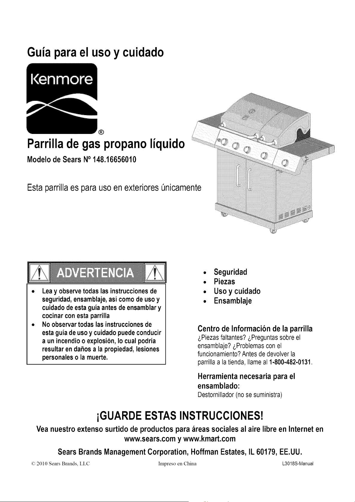
Guia parael usoy cuidado
®
Parrillade gas propanoliquido
Modelode Sears No 148.16656010
Estaparrillaes para usoen exterioresOnicamente
Lea y observe todas las instruccionesde
seguridad, ensamblaje, asi como de uso y
cuidado de esta guia antes de ensamblar y
cocinar con esta parrilla
No observar todas las instrucciones de
esta guia de uso y cuidado puede conducir
a un incendio o explosion, Io cual podria
resultar en dahos a la propiedad, lesiones
personaleso la muerte.
• Seguridad
• Piezas
• Usoy cuidado
• Ensamblaje
Centro de Informacion de la parrilla
z,Piezas faltantes? z,Preguntas sobre el
ensamblaje? _,Problemascon el
funcionamiento?Antes de devolver la
parrilla a la tienda, Ilame al 1-800-482-0131.
Herramientanecesariapara el
ensamblado:
Destornillador (no se suministra)
iGUARDEESTASINSTRUCCIONES!
Vea nuestroextenso surtido de productospara areas sociales al aire libre en Interneten
www.sears.comy www.kmart.com
Sears BrandsManagementCorporation,HoffmanEstates,IL 60179, EE.UU.
(c)2010 Sears Brands, LLC Impreso en China L3018S-Manual
Si detecta olor a gas:
1.Cierre el gas que va a la unidad.
2. Extinga cualquier llama expuesta.
3.Abra la tapa.
4.Si el olor contint_a,mantengase alejado de
la unidady Ilame de inmediato a la
compahia que le suministra el gas o al
departamentode bomberos local.
1. No almacene ni utilice gasolina ni otros
liquidos o vapores inflamables cerca de
esta ni de ninguna otra unidad.
2. No debera almacenar cerca de la parrilla ni
de ninguna otra unidad un cilindro de LP
que no este conectado para ser utilizado.
Llame al Centro de Servicio de Parrillas para obtener
ayuda o repuestos
Si tiene dudas o necesita asistencia durante el ensamblaje,
Ilame al 1-800-482-0131.Hablara con un representante
del fabricante de la parrilla, no con un empleado de Sears.
Para pedir piezas nuevas Ilame a Sears al
1-800-4-MY-HOME.
Registro del producto
IMPORTANTE: Llene la informacionsobre el registro
del producto que aparece a continuacion.
N_odel modelo
N_ode serie
Refierase a la etiqueta de clasificaci6nde la
parrilla para el nQmerode serie.
Fechade compra
PRECAUClON
Para uso residencial t_nicamente.No utilice
para coccion comercial.
PROPOSIClON 65 DE CALIFORNIA
1. Los subproductos de combustion que se
producen cuando se utiliza este producto
contienen sustancias quimicas conocidas
en el Estado de California como
causantes de cancer, defectos congenitos
y otros dahos del sistema reproductor.
2. Esteproductocontienesustanciasquimicas,
incluyendoplomoy componentesde plomo,
conocidosen el Estadode California como
causantesde cancer,defectoscongenitosy
otrosdahosdelsistemareproductor.
Lavese /as manos despu_s de
manipu/ar este producto.
Precauciones de seguridad para la instalacion
• Utilice Ia parrilIa, como Ia compr6, s61ocon gas LP (propano) y
el ensambtede regulador/v_lvutaque se suministra. Deber_
comprarun kit de conversi6n para uso con gas natural.
• La instalaci6n de Ia parrilIadebera conformarse con ta
normativa local, o en ausencia de esta, con ta Normativa
Nacionalpara Combustible de Gas,ANSI Z223.1/NFPA 54,
Normativapara instalaci6n de gas natural y propano, CSA
B149.1, o la Normativa para almacenaje y manejo de
propano, B149.2, o la Normapara vehiculos recreacionales,
ANSI A 119.2/NFPA 1192,y CSA Z240 Serie RV, Normativa
para vehiculos recreacionales,seg_)nsea aplicable.
• Todoslos accesorioselectricos(talescomo el asador)deber_n
estarconectadosa tierra de conformidadcon las normativas
localeso con la Normativa Nacionalsobre Electricidad,ANSI/
NFPA 70o la NormativaCanadiensede Electricidad,CSA
C22.1. Conservelos cablesel6ctricosy/o las manguerasde
suministrode combustiblealejadas de las superficiescalientes.
• Esta parrilla tiene certificaci6n de seguridad para uso en
Estados Unidos y/o Canada Onicamente.No modifique para
utilizar en cuatquier otra ubicaci6n. La modificaci6n
constituir_ un riesgo a la seguridad.
Simbolos de seguridad
Los simbotos y recuadros que aparecen a continuaci6n
explicar Io que cada enunciado significa. Lea y observe todos
los mensajes que se encuentran a traves del manual.
PELIGRO: Indica una situaci6n de peligro
inminenteque, de no evitarse, resultara en muerte
o lesiones graves.
ADVERTENClA: Indica una situaci6n de peligro
potencial que, de no evitarse, podria resultar en
muerte o lesiones graves.
PRECAUCl0N
PRECAUCION: Indica una situaci6n potencial-
mente peligrosa o una practica insegura la cual,
de no evitarse, podria ocasionar lesiones menores
o moderadas.
Para su seguridad.......................................................... 2
Centre de Servicio para ta parriIIa..................................... 2
Informaci6n de registro del producto.................................. 2
Simbotos de seguridad................................................... 2
Precauciones de seguridad para la instataci6n.................... 2
Garantia de Ia parrilIa Kenmore........................................ 3
Uso y cuidado.......................................................... .4-10
Caja de conversi6n a gas natural..................................... 11
Notas 12
.........................................................................
Lista de piezas............................................................. 13
Diagrama de piezas...................................................... 14
Ensambtaje 15-25
Sotuci6n de probtemas............................................. .26-27
Acuerdos de protecci6n para reparaci6n
Felicitaciones por su compra inteligente. Su nuevo producto
Kenmore ®est_ disefiado y fabricado para brindarle aSos de
funcionamiento confiabte. Pero, como cuatquier otro producto,
puede que requiera reparaciones de cuando en cuando. Es atli
cuando tener un Acuerdo de protecci6n para reparaci6n puede
ahorrarle dinero y motestias.
Adquiera un Acuerdo de protecci6n de reparad6n ahora y
prot6jase de molestias y gastos imprevistos.
He aqui Io que el acuerdo de protecci6n para reparaci6nincluye:
[] Servicio experto por parte de nuestros 10.000 especiatistas
profesionates de reparaciones.
[] Servicio ilimitado sin cargo para tas piezas y mano de obra
de todas Ias reparaciones amparadas
[] Reemplazo del producto hasta $1500 si el producto
amparado no puede arreglarse
[] Descuento de110% del precio regular del servicio y Ias
piezas relacionadas instatadas no amparadas por el acuerdo;
tambien, 10% de descuento sobre el precio regular de Ias
revisiones preventivas de mantenimiento
[] Ayuda telef6nica rapida -Ia llamamos Resotuci6n R_pida -
apoyo telef6nico de un representante Sears. Piense en
nosotros como un manual de servicio parlante.
Una vez que haya adquiridoel Acuerdode Protecci6npara repara-
ci6n,una simpleIlamadatelef6nica es todo Io que necesitapara
programarel servicio. Puede Ilamar en cualquiermomento, de dia
o de noche,o programaruna cita de servicioa traves de Intemet.
El Acuerdo de Protecci6n para reparaci6n es una compra sin
riesgos. Si cancela por cuatquier raz6n durante el periodo de
garantia del producto, Ie proporcionaremos un reembotso
compteto. O un reembotso prorrateado en cuatquier momento
despues de que venza et periodo de garantia del producto.
iAdquiera su Acuerdo de Protecci6n para Reparaci6n hoy
mismo!
Ciertas limitaciones y exclusiones aplican.
Para precios e informaci6n adicional, Ilame al 1-800-827-6655.
Servicio de instalaci6n Sears
Para la instalaci6n profesional de electrodom6sticos Sears,
abridores de puertas de garaje, calentadores de agua y
cualquier otro articulo grande en EE.UU., Ilame al
1-800-4-MY-HOME®
Garantia total Kenmore
Siesta parrilla presenta una falla originada por un defecto de material
o mano de obra, dentro de un afio a partir de la fecha de compra,
Ilame al 1-800-4-MY- HOME ® para obtener reparaci6n gratis (o
reemplazo si no fuese posible efectuar la reparaci6n).
Garantia limitada en los quemadores
Durante diez afios a partir de la fecha de compra, cualquier quemador
de acero inoxidable que se oxide completamente sera reemplazado
sin costo. Despues del primer afio a partir de la fecha de compra,
usted paga por la mano de obra si desea que se Io instalen.
Toda la cobertura de garantia excluye las baterias del encendedor y la
perdida de pintura de las partes de la parrilla, la decoloraci6n o el
6xido, los cuales son partes fungibles que pueden gastarse con el uso
normal dentro del periodo de garantia, o son situaciones que podrian
producirse por el uso normal, accidente o mantenimiento inadecuado.
Toda la cobertura de garantia queda anulada si la parrilla se utiliza
para fines comerciales o en alquiler.
Toda la cobertura de garantia aplica Qnicamente si la parrilla se utiliza
en Estados Unidos.
Esta garantia le otorga derechos legales especificos yes posible que
usted goce de otros derechos que varian segQn el estado.
Sears, Roebuck and Co., Hoffman Estates, IL 60179
• NUNCAguardeuncilindroderepuestodeLPdebajo
nicercadela parrillanienunareaencerrada
• NuncaIleneuncilindroa rnasde180%de su capacidad.
• Si la informacion de los dos puntos anteriores no
se sigue exactamente, puede ocurrir un incendio
que ocasione la muerte o lesiones graves.
° Un cilindroque se haya Ilenadoexcesivamenteo
inadecuadamentealmacenadoes un peligrodebido
a la posibilidadde que la valvulade seguridadpara
alivio de la presionliberegas. Esto podria
ocasionarun incendiointensocon riesgo de dahos
a la propiedad,lesionesgraveso la muerte.
• Si ve, hueleo escuchagasescapando,alejese
inmediatamentedel cilindrode LPy de la parrillay
Ilame al departamentode bomberos.
Rernocion del tanque de LP, transporte y almacenaje
• Cierre (girea OFF) todas Ias periIIasde control y Ia valvula del
tanque de LP. Gire Ia tuercade acopleen el sentido antihorario
manualmentesolamente- no utilice herramientaspara
desconectar.Levante el cable del tanquede de LP de IaaniIIadel
tanque LP, Iuego Ievanteel tanquey saque(odet soporte. Instale
Iatapa de seguridaden la valvutadel tanque de LP. Siempre
utiIiceIatapa y Ia bandaque se suministracon ta valvula.
Noutilizarla tapa de seguridadcomo se indicapuede oca-
sionarlesionespersonalesgravesy/o dafio a la propiedad.
Valvuladel _-_
tanque de
Tapade seguridad
Bandaretenedora
• Un tanque de LP desconectado para almacenar o transportar
debera tener cotocada ta tapa de seguridad (como se iIustra).
No atmacene un tanque de LP en espacios cerrados tales como
un puesto de estacionamiento, garaje, porche, patio cubierto u
otro edificio. Nunca deje un tanque de LP dentro de un vehiculo
que pueda recatentarse con el sol.
• Noguarde un tanquede LP en un area donde jueguen los ni_os.
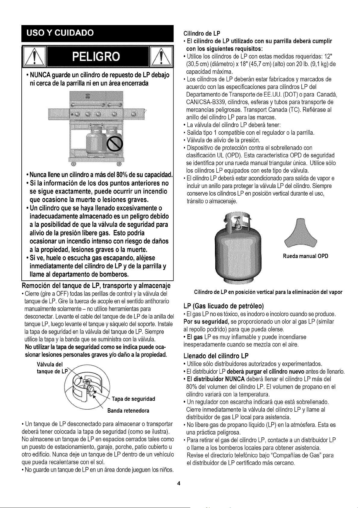
Cilindro de LP
• El cilindro de LP utilizado con su parrilla debera cumplir
con los siguientes requisitos:
• UtiIice los ciIindros de LP con estas medidas requeridas: 12"
(30,5 cm) (diametro) x 18" (45,7 cm) (alto) con 20 lb. (9,1 kg)de
capacidad maxima.
• Los ciIindros de LP deberan estar fabricados y marcados de
acuerdo con tas especificaciones para ciIindros LP del
Departamentode Transporte de EE.UU. (DOT) o para Canada,
CAN/CSA-B339, ciIindros, esferas y tubos para transporte de
mercancias peligrosas. Transport Canada (TC). Refierase at
anilIo del cilindro LP para tas marcas.
• La valvuta del ciIindro LP debera tener:
• Salida tipo 1 compatible con el regutador o Ia parriIIa.
• Valvuta de ativio de Ia presi6n.
• Dispositivo de protecci6n contra el sobrelIenado con
clasificaci6n UL (OPD). Esta caracteristica OPD de seguridad
se identifica por una rueda manual triangular Onica. UtiIices6to
los ciIindros LP equipados con este tipo de valvula.
• El ciIindroLP deberaestar acondicionadoparasalida de vapor e
incluir un aniIIo para proteger Iavalvula LP del ciIindro.Siempre
conserve los ciIindrosLP en posici6n verticaldurante el uso,
transitoo almacenaje.
RuedamanualOPD
Cilindrode LPen posicionverticalpara la eliminaciondelvapor
LP (Gas licuado de petroleo)
• El gas LP no es t6xico, es inodoro e incolorocuando se produce.
Por su seguridad, se proporcionado un otor at gas LP (similar
at repotIo podrido) para que pueda oterse.
• El gas LP es muy inflamabte y puede incendiarse
inesperadamente cuando se mezcla con el aire.
Llenado del cilindro LP
• UtiIices6to distribuidores autorizados y experimentados.
• El distribuidorLP debera purgarel cilindronuevo antes de Ilenarlo.
• El distribuidor NUNCA debera tIenarel ciIindro LP mas del
80% de( volumen de( cilindro LP. El volumen de propano en el
cilindro variara con ta temperatura.
• Un regutador con escarcha indicara que esta sobreilenado.
Cierre inmediatamente Ia valvuta de( cilindro LP y Ilame at
distribuidor de gas LP local para asistencia.
• No Iibere gas de propano Iiquido (LP) en ta atm6sfera. Esta es
una practica peligrosa.
• Pararetirar el gas de( cilindro LP, contacte a un distribuidor LP
o Ilame a los bomberos locales para obtener asistencia.
Revise el directorio telef6nico bajo "Compafiias de Gas" para
el distribuidor de LP certificado mas cercano.

Intercambio del tanque LP
• Muchosdistribuidoresque venden parrilIasofrecenla opci6nde
reemplazarsu tanque vacio de LP a travesde unservicio de
intercambio.Utilices61oIasempresasde intercambiocon repu-
taci6nqueinspeccionan,Ilenancon precisi6n,pruebany certifican
sus cilindros.Intercambie su tanque s61opot un tanque
equipado con la caracteristica de seguridad OPD segun se
describe en la seccibn "Tanque LP" de este manual.
• Siempre conserve los tanques LP nuevos e intercambiados en
posici6n vertical durante el uso, transporte o atmacenaje.
• Haga la prueba de fugas en los tanques LP
intercambiados ANTES de conectarlo a la parrilla.
Prueba de fuga del tanque LP
Parasu seguridad
• La prueba de fuga debera repetirse cada vez que se
intercambia o se rellena un tanque de LP.
• No fume durante Ia prueba de fugas.
• No utilice una llama expuesta para revisar Ias fugas de gas.
• La parrilIa debera probarse en busca de fugas en exteriores,
en un area bien ventilada, atejada de las fuentes de ignici6n
tales como los aparatos de encendido a gas o electrico.
Durante Ia prueba de fugas, mantenga ta parrilIa atejada de Ias
llamas expuestas o chispas.
• Utilice una brocha limpia y una sotuci6n de 50/50 detergente
suave y agua. Aptique Ia sotuci6n jabonosa en tas areas que
indican tasflechas de Ia figura. Las fugas se identiflcan
mediante burbujas crecientes.
Como conectar el regulador al tanque de LP
1. El tanque de LP debera estar adecuadamente fijado a ta
parrilIa. (Refierase a ta secci6n de ensambtaje).
2. Gire todas Ias perilIas de control a la posici6n OFF.
3. Cotoqueel tanque de LP en la posici6nOFF girando Ia rueda
manualOPD en sentidohoratiohasta que se detenga totalmente.
4. Retire Ia tapa protectora de Ia valvuta del tanque LP. Siempre
utilice Ia tapa y Ia banda que se suministran con ta valvula.
Valvula de
seguridad
RuedamanualOPD
_/ Salidatipo 1 con
roscaexterna
/
Banday tapa
Si aparecen burbujas"creciendo" no utilice ni mueva el
tanque de LP. iContacte un distribuidor de gas LP o a
los bomberos!
No inserte un tapon de transporte
POL (pieza plastica con roscas
extemas) en la salida tipo 1 de la
valvula del tanque. Anulara la
funcion de la valvula de seguridad.
• No utiIice agentes Iimpiadores domesticos. Podrian causar
dafios a los componentes y tuberias de gas
(valvuta/manguera/regulador).
5. Sostenga el regutador e inserte el empatme en ta valvuta del
tanque de LP. Apriete a mano Ia tuerca de acopte,
sosteniendo el regutador en tinea recta con ta valvuta del
tanque de LP a obieto de no dafiar Ia rosca.
El empalmetiene queestar
centradoen la valvuladel
tanquede LP
/
¢
/
/
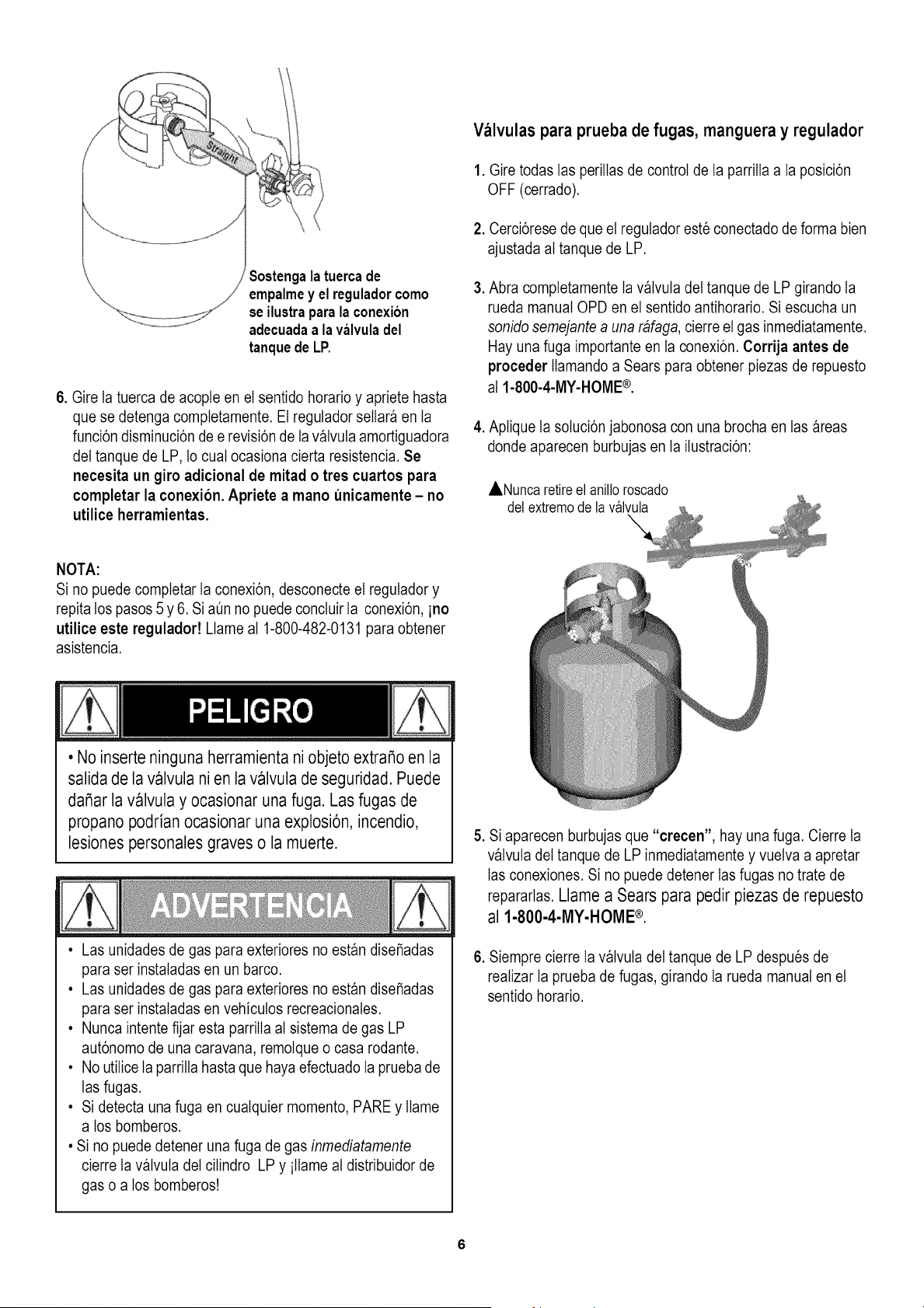
Sostengalatuercade
empalmey el reguladorcomo
se ilustraparala conexi6n
adecuadaa la valvuladel
tanquede LP.
6. Gire Ia tuerca de acopte en el sentido horario y apriete hasta
que se detenga completamente. El regutador sellar_ en ta
funci6n disminuci6n de e revisi6n de Ia v_lvuta amortiguadora
del tanque de LP, Io cuat ocasiona cierta resistencia. Se
necesita un giro adicional de mitad o tres cuartos para
completar la conexi6n. Apriete a mano unicamente - no
utilice herramientas.
Valvulas para prueba de fugas, manguera y regulador
1. Gire todas Ias periIIas de control de Ia parriIIa a la posici6n
OFF (cerrado).
2. Cerci6rese de que el regutador este conectado de forma bien
ajustada at tanque de LP.
3. Abra comptetamente Ia v_lvuta del tanque de LP girando Ia
rueda manual OPD en el sentido antihorario. Si escucha un
sonido semejante a una rafaga, cierre el gas inmediatamente.
Hay una fuga importante en ta conexi6n. Corrija antes de
proceder Ilamando a Sears para obtener piezas de repuesto
al 1-800-4-MY-HOME®.
4. Aptique Ia sotuci6n jabonosa con una brocha en tas areas
donde aparecen burbujas en ta ilustraci6n:
ANunca retireel anilloroscado
del extremode la v_lvula
NOTA:
Si no puede comptetar Ia conexi6n, desconecte el regutador y
repita los pasos 5 y 6. Si aQn no puede concluir Ia conexi6n, ino
utilice este reguladort Llame at 1-800-482-0131 para obtener
asistencia.
• No inserte ninguna herramienta ni objeto extraSoen la
salida de la valvula ni en la valvulade seguridad. Puede
daSar la valvula y ocasionar unafuga. Las fugas de
propano podrian ocasionar una explosi6n, incendio,
lesiones personalesgraves o la muerte.
• Las unidades de gas para exteriores no est_n disefiadas
para ser instatadas en un barco.
• Las unidades de gas para exteriores no est_n disefiadas
para ser instatadas en vehicutos recreacionates.
• Nunca intente fijar esta parrilIa at sistema de gas LP
aut6nomo de una caravan& remotque o casa rodante.
• No utilice Ia parrilIa hastaque haya efectuado Ia prueba de
Iasfugas.
• Si detecta una fuga en cualquier momento, PARE y Ilame
a los bomberos.
• Si no puede detener una fuga de gas inmediatamente
cierre Ia v_lvuta del cilindro LP y itlame at distribuidor de
gas o a los bomberos!
5. Si aparecen burbujas que "crecen", hay una fuga. Cierre Ia
v_lvuta del tanque de LP inmediatamente y vuelva a apretar
Ias conexiones. Si no puede detener Ias fugas no trate de
repararlas. Llame a Sears para pedir piezas de repuesto
al 1-800-4-MY-HOME ®.
6. Siempre cierre Ia valvuta del tanque de LP despues de
reatizar Ia prueba de fugas, girando Ia rueda manual en el
sentido horario.
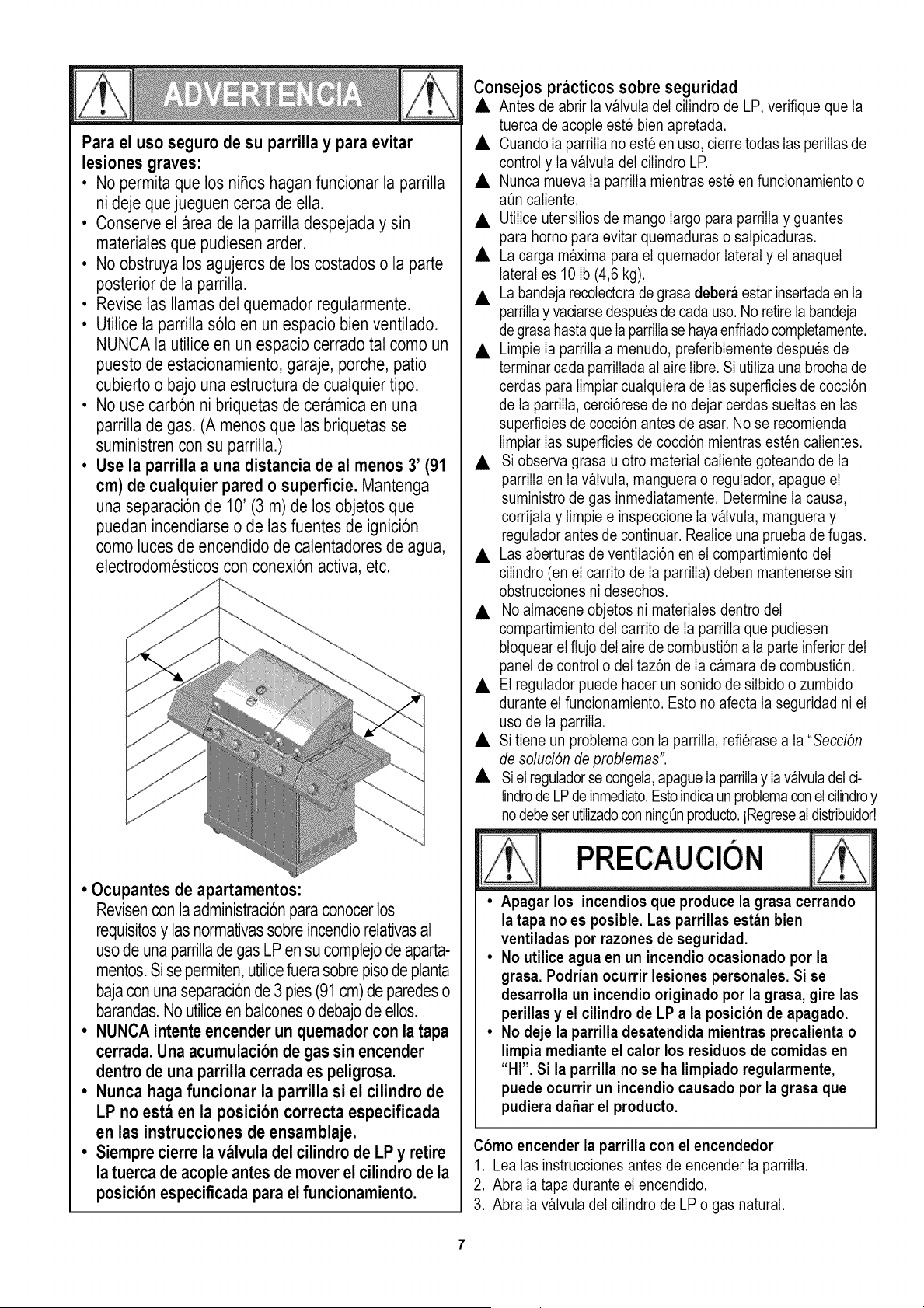
Para el uso seguro de su parrilla y para evitar
lesiones graves:
• No permita que los ni_os haganfuncionar la parrilla
ni deje que jueguen cerca de ella.
• Conserve el area de la parrilladespejada y sin
materialesque pudiesen arder.
• No obstruya los agujeros de los costados o la parte
posteriorde la parrilla.
• Revise las llamas del quemador regularmente.
• Utilice la parrillas61oen un espacio bien ventilado.
NUNCA la utilice en un espacio cerrado tal como un
puesto de estacionamiento, garaje, porche, patio
cubierto o bajo una estructura de cualquier tipo.
• No use carb6n ni briquetas de ceramica en una
parrilla de gas. (A menos que las briquetas se
suministren con su parrilla.)
• Use la parrilla a una distancia de al menos 3' (91
cm) de cualquier pared o superficie. Mantenga
una separaci6nde 10' (3 m) de los objetos que
puedan incendiarse o de las fuentes de ignici6n
como luces de encendido de calentadoresde agua,
electrodomesticos con conexi6n activa, etc.
/
J
J
J
j_
/
/
/
• Ocupantes de apartamentos:
Revisencon la administraci6nparaconocerlos
requisitosy las normativassobreincendiorelativasal
usode una parrillade gas LPen su complejode aparta-
mentos.Si se permiten,utilicefuerasobrepisodeplanta
bajacon unaseparaci6nde 3 pies(91cm) de paredeso
barandas.No utiliceen balconeso debajode ellos.
• NUNCA intente encender un quemador con la tapa
cerrada. Una acumulaci6n de gas sin encender
dentro de una parrilla cerrada es peligrosa.
• Nunca haga funcionar la parrilla si el cilindro de
LP no est,_ en la posici6n correcta especificada
en las instrucciones de ensamblaje.
• Siempre cierre la valvula del cilindro de LP y retire
la tuerca de acople antes de mover el cilindro de la
posicion especificada para el funcionamiento.
Consejos practicos sobre seguridad
• Antes de abrir Ia v_lvuta del ciIindro de LP, verifique que Ia
tuerca de acople este bien apretada.
• Cuando Ia parrilIa no este en uso, cierre todas Ias perilIas de
control y Ia v_lvuta del ciIindro LP.
• Nunca mueva ta parriIIa mientras este en funcionamiento o
aQncatiente.
• UtiIiceutensiIios de mango largo para parriIIa y guantes
para homo para evitar quemaduras o satpicaduras.
• La carga maxima para el quemador lateral y el anaquel
lateral es 10 Ib (4,6 kg).
• Labandejarecotectorade grasa debera estar insertadaen la
parrilIay vaciarsedespues de cada uso. No retire Ia bandeja
de grasahasta que IaparriIIase hayaenfriado completamente.
• Limpie Ia parriIIa a menudo, preferibtemente despues de
terminar cada parriIIadaat aire Iibre. Si utiIiza una brocha de
cerdas para timpiar cuatquiera de tas superficies de cocci6n
de Ia parrilIa, cerci6rese de no dejar cerdas sueltas en las
superficies de cocci6n antes de asar. No se recomienda
Iimpiar Ias superficies de cocci6n mientras esten calientes.
• Si observa grasa u otro material caliente goteando de Ia
parriIIaen ta v_lvuta, manguera o regulador, apague el
suministro de gas inmediatamente. Determine Ia causa,
corrijata y Iimpie e inspeccione Ia v_lvuta, manguera y
regutador antes de continuar. Realice una prueba de fugas.
• Las aberturas de ventilaci6n en el compartimiento del
ciIindro (en el carrito de Ia parriIIa)deben mantenerse sin
obstrucciones ni desechos.
• No atmacene objetos ni materiates dentro del
compartimiento del carrito de Ia parriIIaque pudiesen
btoquear el flujo del aire de combusti6n a la parte inferior del
panel de control o del taz6n de Ia camara de combusti6n.
• El regutador puede hacer un sonido de siIbido o zumbido
durante el funcionamiento. Esto no afecta ta seguridad ni el
uso de Ia parrilIa.
• Si tiene un probtema con ta parrilIa, refierase a ta "Secci6n
de solud6n de problemas".
• Siel reguladorse congeta,apagueIa parrilIay Iav_lvuladetci-
Iindrode LP de inmediato.Estoindicaun probtemaconet ciIindroy
nodebeser utiIizadoconningt_nproducto,iRegresealdistribuidod
• Apagar los incendios que produce la grasa cerrando
la tapa no es posible. Las parrillas estan bien
ventiladas por razones de seguridad.
• No utilice agua en un incendio ocasionado por la
grasa. Podrian ocurrir lesiones personales. Si se
desarrolla un incendio originado por la grasa, gire las
perillas y el cilindro de LP a la posicion de apagado.
• No deje la parrilla desatendida mientras precalienta o
limpia mediante el calor los residuos de comidas en
"HI". Si la parrilla no se ha limpiado regularmente,
puede ocurrir un incendio causado por la grasa que
pudiera daSarel producto.
Como encender la parrilla con el encendedor
1. Lea tas instrucciones antes de encender Ia parriIIa.
2. Abra ta tapa durante el encendido.
3. Abra ta v_lvuta del cilindro de LPo gas natural.
4. PresionehaciaadentrocualquierperilIadecontroldelquema-
dorygireIaperiIIahacialaizquierdaalaposici6n"HI".ContinQe
presionandoIaperiIIahastaqueelquemadorseencienda.
5.Sinoenciendeen5 segundos,apagueelcontroldel
quemador,espere5minutosparaquesedisipeelgasy
repitaelprocedimientodeencendido.
6.Paraencenderotrosquemadores,repitaelpaso4.
NOTA:Sielencendedornofunciona,sigalasinstrucciones
deencendidoconf6sforos.
Apague (coloque en OFF) los controles y la alimen-
tacion de qas del tanaue cuando no este en uso.
Si no enciende en 5 segundos, apague el controldel
quemador, espere 5 minutos y repita el procedimiento
de encendido. Si el quemador no enciende con la
valvula abierta, el gas continuarafluyendo por el
quemador y podria encenderse accidentalmente con el
riesgo de lesiones.
Encendido con fosforos
• No se incline sobre la parrilla para encenderla.
1. Abra la tapa durante el encendido.
2. Cotoque et f6sforo en el portaf6sforos (que cuelga del
costado det carrito). Encienda el f6sforo, cot6quelo en ta
c_mara de combusti6n.
3. Presione hacia adentro y gire Ia periIla derecha a ta posici6n
HIGH. Cerci6rese de que el quemador prende y permanece
encendido.
4. Encienda otros quemadores presionando Ia periIIa hacia
adentro y girando a ta posici6n HI.
Encendido del quemador lateral con fosforo
1. Abra la tapa del quemador lateral. Abra el gas en el
ciIindro LP
2. Cotoque el f6sforo encendido cerca del quemador.
3. Gire Ia periIIadel quemador lateral a HI. Cerci6rese de que el
quemador prende y permanece encendido.
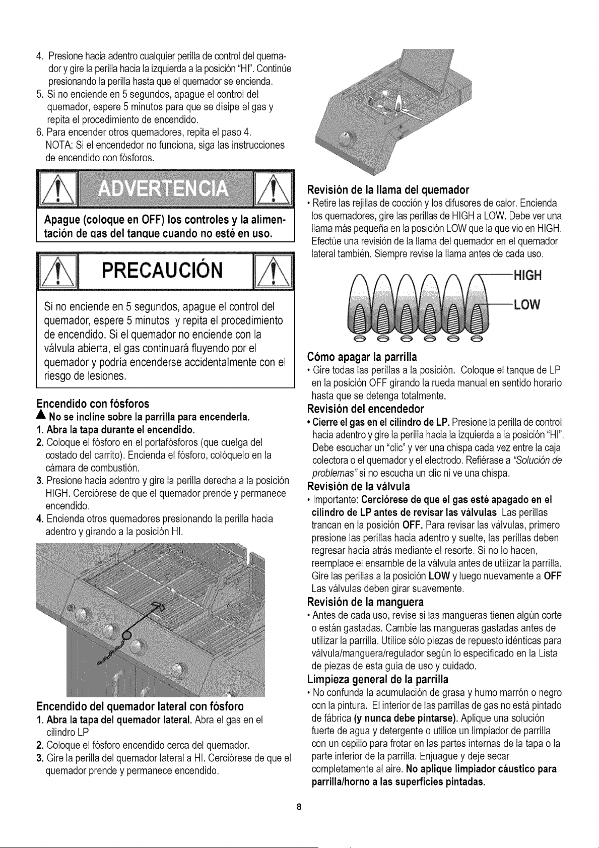
Revision de la llama del quemador
• RetireIas rejiIIasde cocci6n y los difusores de calor. Encienda
los quemadores, gire Ias periIIasde HIGH a LOW. Debever una
llama m_s pequefia en la posici6n LOW que Ia que vio en HIGH.
EfectQeuna revisi6n de Ia llama del quemador en el quemador
lateral tambien. Siempre revise Ia llama antes de cada uso.
C6mo apagar la parrilla
• Gire todas Ias periIIasa la posici6n. Cotoque el tanque de LP
en ta posici6n OFF girando Ia rueda manual en sentido horario
hasta que se detenga totalmente.
Revision del encendedor
• Cierre el gas en el cilindrode LP. Presione IaperiIIade control
hacia adentro y gire IaperiIIa hacia la izquierdaa la posici6n"HI".
Debe escuchar un "clic" y ver una chispa cada vez entre Iacaja
cotectorao el quemador y el electrodo. Refierasea "Solud6n de
problemas"si no escucha un clic nive una chispa.
Revision de la valvula
• Importante: Cerciorese de que el gas este apagado en el
cilindro de LP antes de revisar las valvulas. Las perilIas
trancan en la posici6n OFF. Para revisar Iasv_lvutas, primero
presione Ias periIIas hacia adentro y suelte, Ias periIIas deben
regresar hacia atr_s mediante el resorte. Si no Io hacen,
reemptace el ensambte de Ia valvuta antes de utiIizar Ia parriIIa.
Gire Ias perilIas a ta posici6n LOW y Iuego nuevamente a OFF
Las v_lvutas deben girar suavemente.
Revision de la manguera
• Antes de cada uso, revise si Ias mangueras tienen atg_n corte
o est_n gastadas. Cambie Ias mangueras gastadas antes de
utiIizar Ia parriIIa. UtiIices6to piezas de repuesto identicas para
valvuta/manguera/regutador segOn lo especificado en la Lista
de piezas de esta guia de uso y cuidado.
Limpieza general de la parrilla
• No confunda ta acumutaci6n de grasa y humo marr6n o negro
con ta pintura. Elinterior de Ias parriIIasde gas no est_ pintado
de Dbrica (y nunca debe pintarse). Aptique una soluci6n
fuerte de agua y detergente o utiIice un timpiador de parriIIa
con un cepiIIo para frotar en tas partes internas de Ia tapa o Ia
parte inferior de Ia parrilIa. Enjuague y deje secar
completamente at aire. No aplique limpiador caustico para
parrilla/horno a las superficies pintadas.
• Partesplasticas: Lave con agua caliente jabonosa y seque.
No utiIice Citrisot, Iimpiadores abrasivos, desengrasadores ni
un timpiador concentrado para parrilIa en tas partes pDsticas.
Pueden ocurrir daSos y fatIa en esas partes.
• Superficies de porcelana: Debido a ta composici6n
semejante al vidrio, Ia mayoria de los residuos pueden
Iimpiarse con una sotuci6n de bicarbonato de soda/agua o un
Iimpiadorespeciatmente formulado. UtiIicepotvo no abrasivo
parafrotar Ias manchas rebeldes.
• Superficies pintadas: Lave con detergente suave o Iimpiador
no abrasivo y agua jabonosa tibia. Seque con un paso suave
no abrasivo.
• Superficies de acero inoxidable: Para conservar Ia
apariencia de atta catidadde su parrilIa, Dvela con agua tibia y
detergente suave y sequela con un paso suave despues de
cada uso. Los dep6sitos de grasa adherida podr_n requerir el
uso de una atmohadilIa de Iimpieza pDstica abrasiva. Utilice
s6to en ta direcci6n del acabado cepilIado para evitar daSos.
No utilice Ia atmohadilIa abrasiva en areas con graficos.
• Superficies de coccion: Si utiIiza una brocha de cerdas para
Iimpiar cualquiera de Ias superficies de cocci6n de Ia parrilla,
cerci6rese de no dejar cerdas sueltas en las superficies de
cocci6n antes de asar. No se recomienda limpiar Ias
superficies de cocci6n mientras esten catientes.
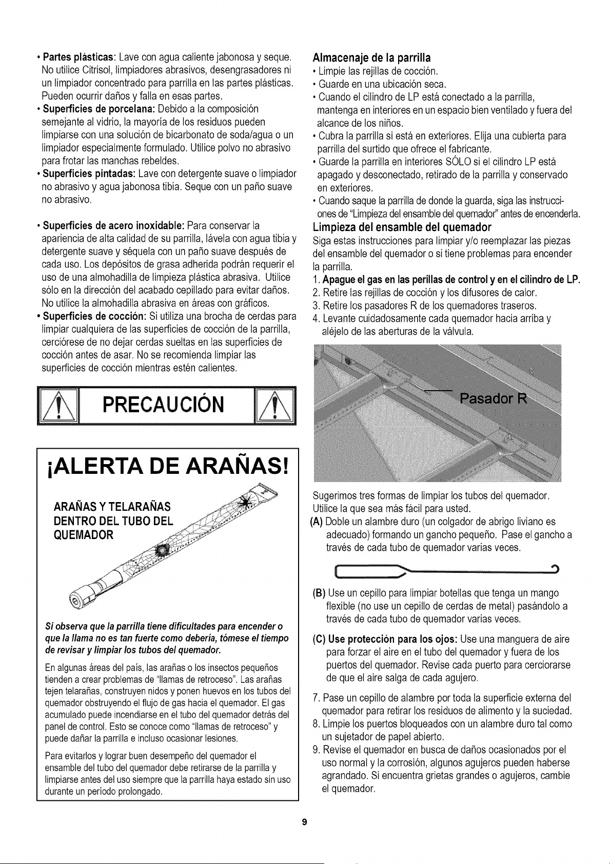
Almacenaje de la parrilla
•Limpie las rejilIasde cocci6n.
• Guarde en una ubicaci6n seca.
• Cuando el cilindro de LP est_ conectado a ta parrilla,
mantenga en interiores en un espacio bienventiIado y fuera del
atcance de los niSos.
• Cubra ta parrilIa si esta en exteriores. Elija una cubierta para
parrilIa del surtido que ofrece el fabricante.
• Guarde la parrilIa en interiores SOLO si el cilindro LP esta
apagado y desconectado, retirado de Ia parriIIa y conservado
en exteriores.
• Cuandosaque Ia parrilIade donde Ia guarda,siga tas instrucci-
ones de "Limpiezadel ensambledetquemador"antesde encenderta.
Lirnpieza del ensamble del quemador
Siga estas instrucciones para timpiar y/o reemplazar Ias piezas
del ensambte del quemador o si tiene probtemas para encender
Ia parrilIa.
1. Apague el gas en las perillas de control y en el cilindro de LP.
2. Retire Ias rejilIas de cocci6n y los difusores de cator.
3. Retire los pasadores R de los quemadores traseros.
4. Levante cuidadosamente cada quemador hacia arriba y
alejelo de Ias aberturas de Ia v_lvuta.
iALERTA DE ARANAS!
Si observaque la parrillatiene dificultades para encendero
quela llama no es tan fuerte como deberia, t6mese el tiempo
derevisar y limpiar los tubos del quemador.
Enalgunas_reasdel pals,las araSaso los insectospequeSos
tiendena crear problemasde"llamasde retroceso'.LasaraSas
tejentelaraSas,construyennidosy ponen huevosen lostubosdel
quemadorobstruyendoelflujo de gas haciael quemador.El gas
acumuladopuedeincendiarseen el tubodel quemadordetr_sctel
paneldecontrol.Estose conocecomo"llamasde retroceso"y
puededaSarla parrillae inclusoocasionarlesiones.
Paraevitarlosy IograrbuendesempeSoctelquemadorel
ensambledeltubo ctelquemadordeberetirarsede laparrillay
limpiarseantesdelusosiemprequela parrillahayaestadosinuso
cturanteun periodoprolongado.
Sugerimos tres formas de Iimpiar los tubos del quemador.
UtiIice Ia que sea m_s DciI para usted.
(A) Dobteun alambre duro (un cotgador de abrigo Iiviano es
adecuado) formando un gancho pequeSo. Pase el gancho a
traves de cada tubo de quemador varias veces.
(B) Use un cepiIIo para timpiar botelIas que tenga un mango
flexible (no use un cepilIo de cerdas de metal) pas_ndoto a
traves de cada tubo de quemador varias veces.
(C) Use proteccion para los ojos: Use una manguera de aire
para forzar el aire en el tubo del quemador y fuera de los
puertos del quemador. Revise cada puerto para cerciorarse
de que el aire satga de cada agujero.
7. Pase un cepiIIo de atambre por toda ta superficie externa del
quemador para retirar los residuos de atimento y la suciedad.
8. Limpie los puertos btoqueados con un atambre duro tat como
un sujetador de papel abierto.
9. Revise el quemador en busca de daSos ocasionados por el
uso normal y Ia corrosi6n, atgunos agujeros pueden haberse
agrandado. Si encuentra grietas grandes o agujeros, cambie
el quemador.
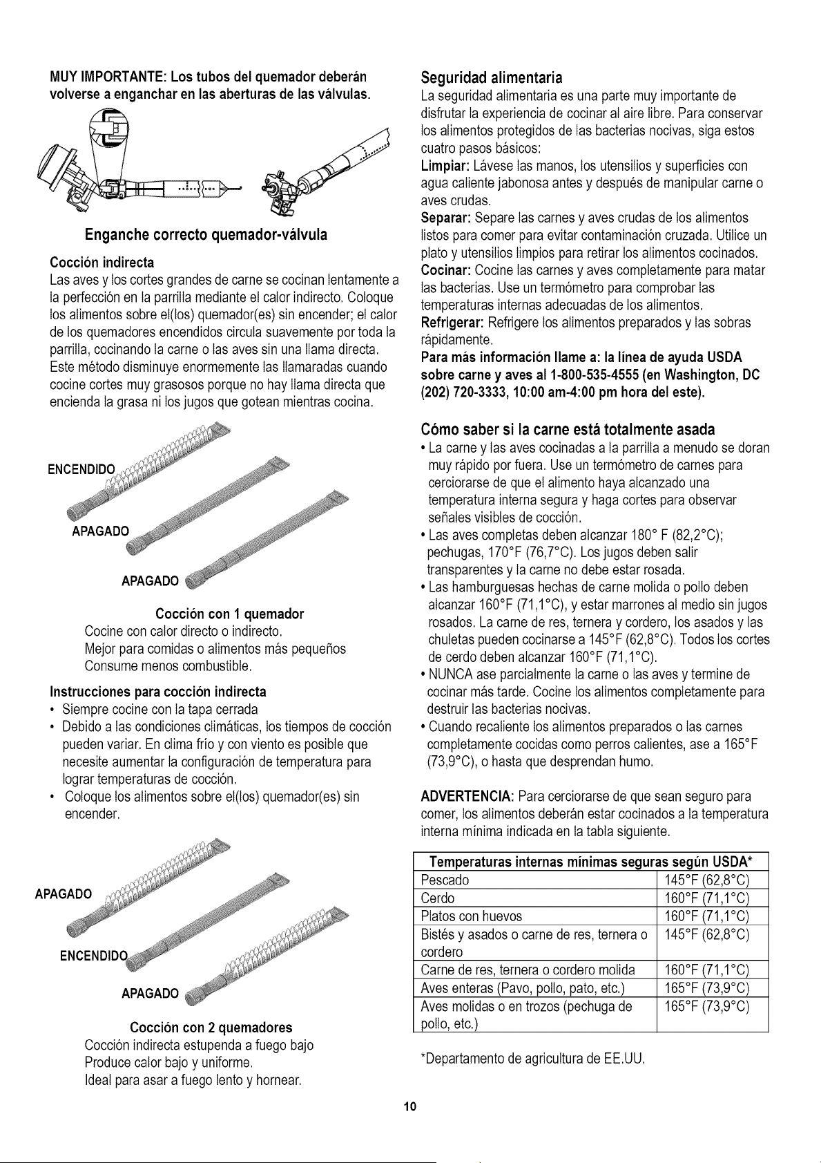
MUY IMPORTANTE: Los tubos del quemador deberan
volverse a enganchar en las aberturas de las valvulas.
Enganche correcto quernador-valvula
Coccion indirecta
Las aves y los cortes grandes de came se cocinan tentamente a
Ia perfecci6n en la parrilIa mediante el calor indirecto. Cotoque
los alimentos sobre el(los) quemador(es) sin encender; el calor
de los quemadores encendidos circuta suavemente por toda ta
parrilIa, cocinando Ia came o Ias aves sin una llama directa.
Este metodo disminuye enormemente Ias Ilamaradas cuando
cocine cortes muy grasosos porque no hay llama directa que
encienda ta grasa ni los jugos que gotean mientras cocina.
Coccion con 1 quemador
Cocine con cator directo o indirecto.
Mejor para comidas o atimentos m_s pequeSos
Consume menos combustible.
Instrucciones para coccion indirecta
• Siempre cocine con ta tapa cerrada
• Debido a tas condiciones clim_ticas, los tiempos de cocci6n
pueden variar. En clima frio y con viento es posibte que
necesite aumentar Ia configuraci6n de temperatura para
Iograr temperaturas de cocci6n.
• Cotoque los atimentos sobre el(los) quemador(es) sin
encender.
Coccion con 2 quemadores
Cocci6n indirecta estupenda a fuego bajo
Produce cator bajo y uniforme.
Ideal para asar a fuego lento y hornear.
10
Seguridad alirnentaria
La seguridad atimentaria es una parte muy importante de
disfrutar Ia experiencia de cocinar at aire Iibre. Para conservar
los alimentos protegidos de Ias bacterias nocivas, siga estos
cuatro pasos b_sicos:
Limpiar: L_vese Ias manos, los utensilios y superficies con
agua catiente jabonosa antes y despues de manipular came o
aves crudas.
Separar: Separe Ias carnes y aves crudas de los atimentos
Iistos para comer para evitar contaminaci6n cruzada. Utilice un
plato y utensilios Iimpios para retirar los atimentos cocinados.
Cocinar: Cocine Ias carnes y aves comptetamente para matar
Ias bacterias. Use un term6metro para comprobar Ias
temperaturas internas adecuadas de los atimentos.
Refrigerar: Refrigere los atimentos preparados y Ias sobras
r_pidamente.
Para mas informaci6n Ilame a: la linea de ayuda USDA
sobre came y ayes al 1-800-535-4555 (en Washington, DC
(202) 720-3333, 10:00 am-4:00 pm hora del este).
Como saber si la carne esta totalmente asada
• La came y las aves cocinadas a ta parriIIaa menudo se doran
muy r_pido por fuera. Use un term6metro de carnes para
cerciorarse de que el alimento haya atcanzado una
temperatura interna segura y haga cortes para observar
se_ates visibtes de cocci6n.
• Las aves completas deben atcanzar 180° F (82,2°C);
pechugas, 170°F (76,7°C). Los jugos deben salir
transparentes y Ia came no debe estar rosada.
• Las hamburguesas hechas de came motida o polio deben
alcanzar 160°F (71,1°C), y estar marrones at medio sin jugos
rosados. La came de res, ternera y cordero, los asados y Ias
chutetas pueden cocinarse a 145°F (62,8°C). Todos los cortes
de cerdo deben atcanzar 160°F (71,1°C).
• NUNCA ase parciatmente Ia came o Ias aves y termine de
cocinar m_s tarde. Cocine los atimentos completamente para
destruir las bacterias nocivas.
• Cuando recatiente los atimentos preparados o Ias carnes
comptetamente cocidas como perros catientes, ase a 165°F
(73,9°C), o hasta que desprendan humo.
ADVERTENCIA: Para cerciorarse de que sean seguro para
comer, los alimentos deber_n estar cocinados a ta temperatura
interna minima indicada en la tabta siguiente.
Temperaturas internas minimas seguras segun USDA*
Pescado 145°F (62,8°C)
Cerdo 160°F (71,1°C)
Platos con huevos 160°F (71,1°C)
Bistes y asados o came de res, ternera o 145°F (62,8°C)
cordero
Came de res, ternera o cordero motida 160°F (71,1°C)
Aves enteras (Pavo, polio, pato, etc.) 165°F (73,9°C)
Aves motidas o en trozos (pechuga de 165°F (73,9°C)
polio, etc.)
*Departamento de agricuttura de EE.UU.

Para comprar las piezas para conversi6n a gas natural
Ilame a Sears al
1-800-4-MY-HOME®
Kit para conversion a gas natural
$61oun tecnico de gas calificado puede convertir su
parrilla a gas natural con este kit de conversi6n Para
convertir esta parrilla el tecnico necesitaraeste kit de
conversi6n.
Manguera de 12' (3,7 m) para gas natural
Si desea convertir la parrilla a gas natural, el tecnico
necesitara en la mayoria de los casos esta manguerade
extensi6n de 12' (3,7 m) con 3/8" ID (diametro interno), la
cual viene incluida en el kit de conversi6n de gas natural.
11
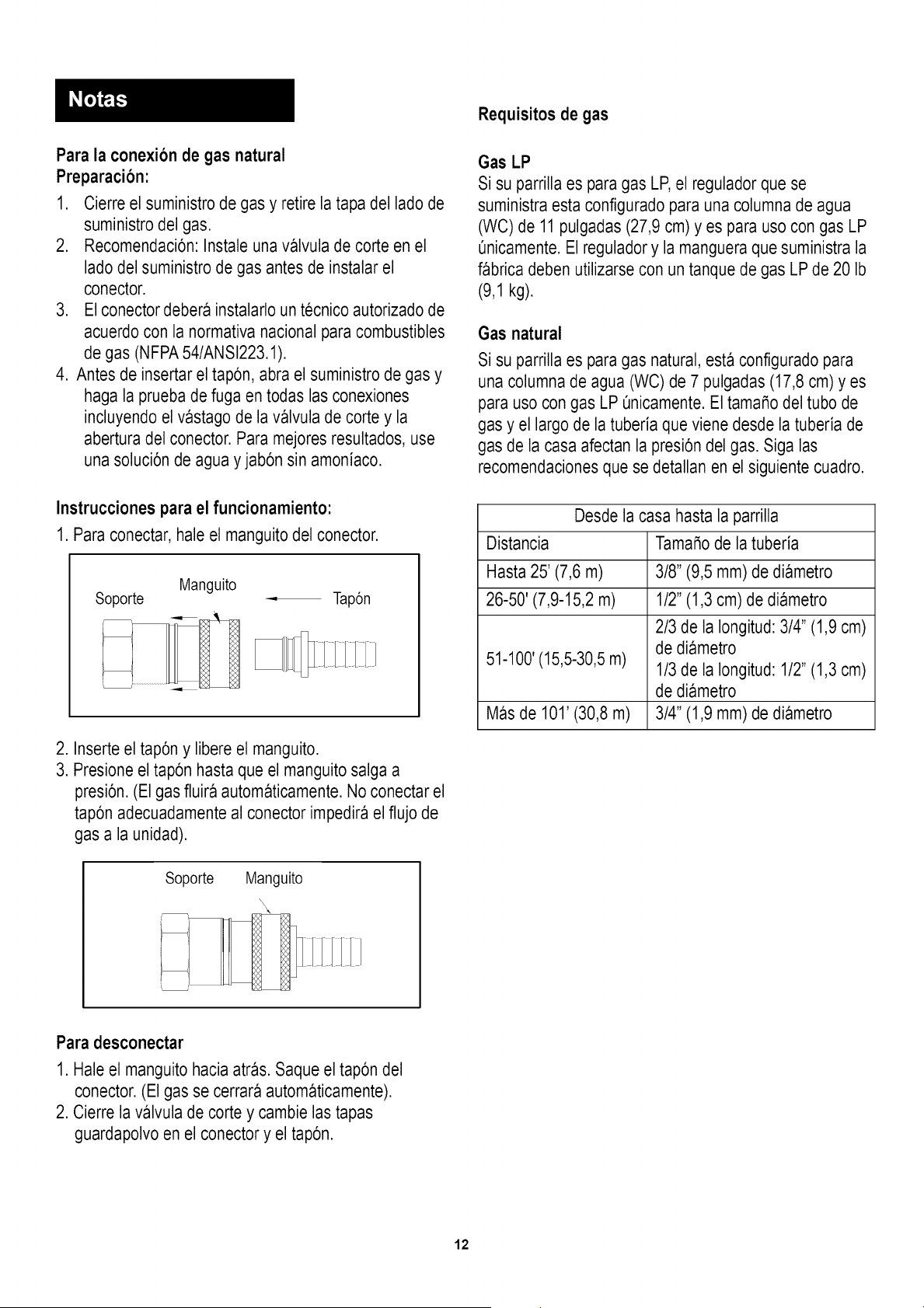
Para la conexion de gas natural
Preparacion:
1. Cierre el suministro de gas y retire la tapa del lado de
suministro del gas.
2. Recomendaci6n: Instale una valvula de corte en el
lado del suministro de gas antes de instalar el
conector.
3. El conector debera instalarlo un tecnico autorizado de
acuerdo con la normativa nacional para combustibles
de gas (NFPA54/ANSI223.1).
4. Antes de insertar el tap6n, abra el suministro de gas y
haga la prueba de fuga en todas las conexiones
incluyendo el vastago de la valvula de corte y la
abertura del conector. Para mejores resultados, use
una soluci6n de agua y jab6n sin amoniaco.
Instrucciones para el funcionamiento:
1. Para conectar, hale el manguito del conector.
Manguito
Soporte _ Tap6n
2. Inserte el tap6n y libere el manguito.
3. Presione el tap6n hasta que el manguito salga a
presi6n. (El gas fluira automaticamente. No conectar el
tap6n adecuadamente al conector impedira el flujo de
gas a la unidad).
Requisitos de gas
Gas LP
Si su parrilla es para gas LP,el regulador que se
suministra esta configurado para una columna de agua
(WC) de 11pulgadas (27,9 cm) yes para uso con gas LP
Qnicamente.El regulador y la manguera que suministra la
fabrica deben utilizarse con un tanque de gas LPde 20 Ib
(9,1 kg).
Gas natural
Si su parrilla es para gas natural, esta configurado para
una columnade agua (WC) de 7 pulgadas (17,8 cm) yes
para uso con gas LP Qnicamente.El tamaSo del tubo de
gas y el largo de la tuberia que viene desde la tuberia de
gas de la casa afectan la presi6n del gas. Siga las
recomendacionesque se detallan en el siguiente cuadro.
Distancia
Hasta 25' (7,6 m)
26-50' (7,9-15,2 m)
51-100'(15,5-30,5m)
Mas de 101' (30,8 m)
Desde la casa hasta la parrilla
TamaSode la tuberia
3/8" (9,5 mm) de diametro
1/2" (1,3 cm) de diametro
2/3 de la Iongitud: 3/4" (1,9 cm)
de diametro
1/3 de la Iongitud: 1/2" (1,3 cm)
de diametro
3/4" (1,9 mm) de diametro
Soporte Manguito
\\
Para desconectar
1. Hale el manguito hacia atras. Saque el tap6n del
conector. (El gas se cerrara automaticamente).
2. Cierre la valvula de corte y cambie las tapas
guardapolvo en el conector y el tap6n.
12
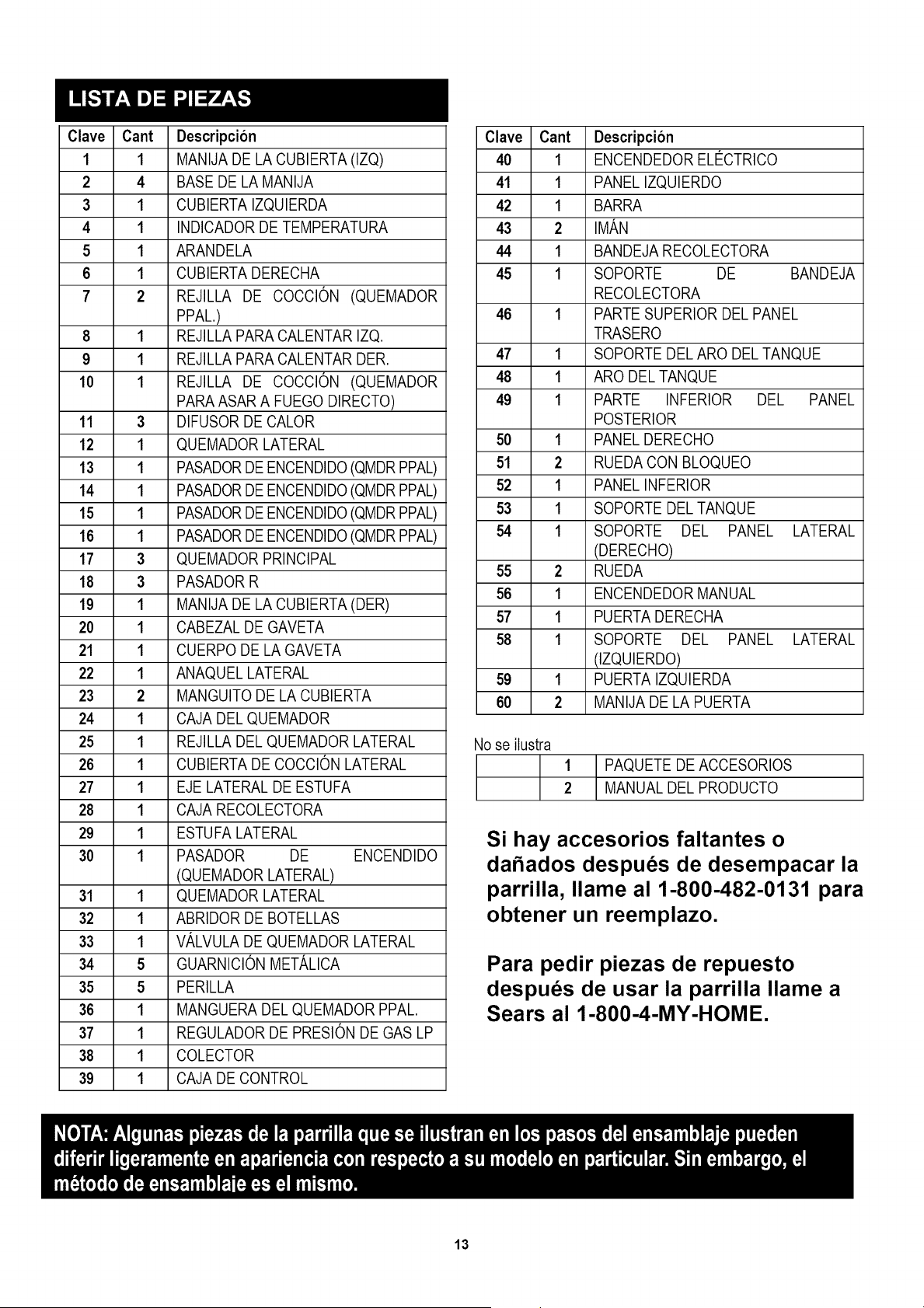
Clave Cant Descripcion
1 1 MANIJA DE LA CUBIERTA (IZQ)
2 4 BASE DE LA MANIJA
3 1 CUBIERTA IZQUIERDA
4 1 INDICADOR DE TEMPERATURA
5 1 ARANDELA
6 1 CUBIERTA DERECHA
7 2 REJILLA DE COCCION (QUEMADOR
PPAL.)
8 1 REJILLA PARA CALENTAR IZQ.
9 1 REJILLA PARA CALENTAR DER.
10 1 REJILLA DE COCCl0N (QUEMADOR
PARA ASAR A FUEGO DIRECTO)
11 3 DIFUSOR DE CALOR
12 1 QUEMADOR LATERAL
13 1 PASADORDE ENCENDIDO(QMDR PPAL)
14 1 PASADORDE ENCENDIDO(QMDR PPAL)
15 1 PASADORDE ENCENDIDO(QMDR PPAL)
16 1 PASADORDE ENCENDIDO(QMDR PPAL)
17 3 QUEMADOR PRINCIPAL
18 3 PASADOR R
19 1 MANIJA DE LA CUBIERTA (DER)
20 1 CABEZAL DE GAVETA
21 1 CUERPO DE LA GAVETA
22 1 ANAQUEL LATERAL
23 2 MANGUITO DE LA CUBIERTA
24 1 CAJA DEL QUEMADOR
25 1 REJILLA DEL QUEMADOR LATERAL
26 1 CUBIERTA DE COCClON LATERAL
27 1 EJE LATERAL DE ESTUFA
28 1 CAJA RECOLECTORA
29 1 ESTUFA LATERAL
30 1 PASADOR DE ENCENDIDO
(QUEMADOR LATERAL)
31 1 QUEMADOR LATERAL
32 1 ABRIDOR DE BOTELLAS
33 1 VALVULA DE QUEMADOR LATERAL
34 5 GUARNICION METALICA
35 5 PERILLA
36 1 MANGUERA DEL QUEMADOR PPAL.
37 1 REGULADOR DE PRESION DE GAS LP
38 1 COLECTOR
39 1 CAJA DE CONTROL
Clave Cant Descripcion
40 1 ENCENDEDOR ELECTRICO
41 1 PANEL IZQUIERDO
42 1 BARRA
43 2 IMAM
44 1 BANDEJA RECOLECTORA
45 1 SOPORTE DE BANDEJA
RECOLECTORA
46 1 PARTE SUPERIOR DEL PANEL
TRASERO
47 1 SOPORTE DEL ARO DEL TANQUE
48 1 ARO DEL TANQUE
49 1 PARTE INFERIOR DEL PANEL
POSTERIOR
50 1 PANEL DERECHO
51 2 RUEDA CON BLOQUEO
52 1 PANEL INFERIOR
53 1 SOPORTE DEL TANQUE
54 1 SOPORTE DEL PANEL LATERAL
(DERECHO)
55 2 RUEDA
56 1 ENCENDEDOR MANUAL
57 1 PUERTA DERECHA
58 1 SOPORTE DEL PANEL LATERAL
(IZQUIERDO)
59 1 PUERTA IZQUIERDA
60 2 MANIJA DE LA PUERTA
No se ilustra
1 PAQUETE DE ACCESORIOS
2 MANUAL DEL PRODUCTO
Si hay accesorios faltantes o
da_ados despues de desempacar la
parrilla, Ilame al 1-800-482-0131 para
obtener un reemplazo.
Para pedir piezas de repuesto
despues de usar la parrilla Ilame a
Sears al 1-800-4-MY-HOME.
13
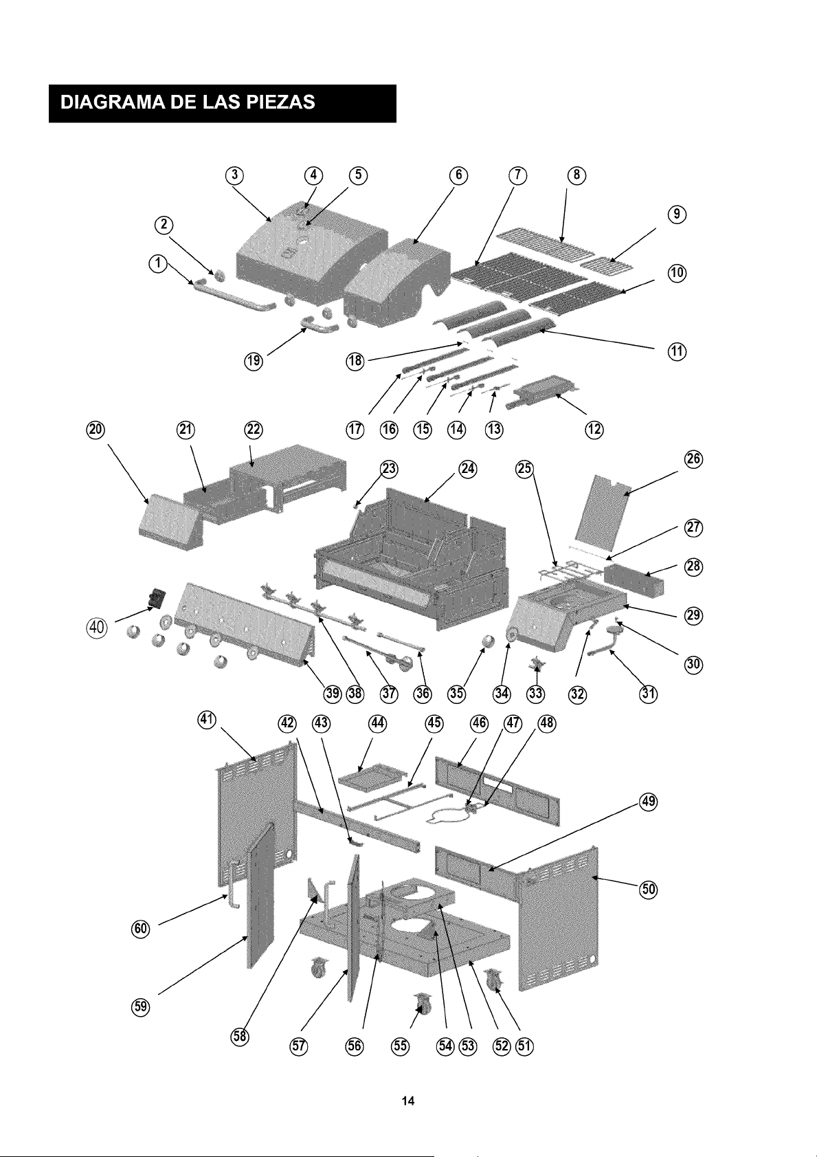
®
® ® ® ®
® ®
®
®
@ ®
®
@ @ @ ®®@@@ @
@
®
\
®® ® ® ®
@
@
@
@
@
@
@ @ @ @@ @@
14
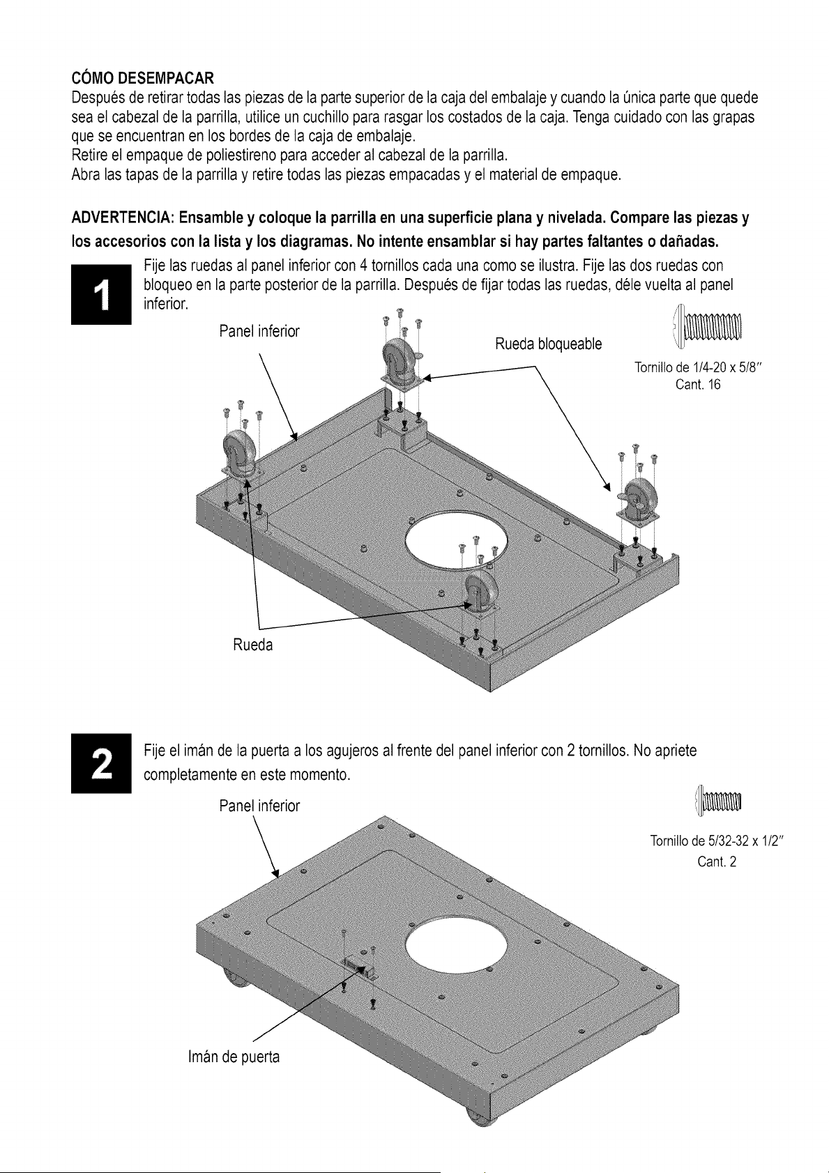
COMO DESEMPACAR
Despues de retirar todas las piezasde la parte superior de la caja del embalaje y cuando la Onicaparte que quede
sea el cabezal de la parrilla, utilice un cuchillo para rasgar los costados de la caja. Tengacuidado con lasgrapas
que se encuentran en los bordes de la caja de embalaje.
Retire el empaque de poliestireno para acceder al cabezal de la parrilla.
Abra las tapas de la parrilla y retire todas las piezas empacadas y el material de empaque.
ADVERTENCIA: Ensamble y coloque la parrilla en una superficie plana y nivelada. Compare las piezas y
los accesorios con la lista y los diagramas. No intenteensamblar si hay partes faltantes o dahadas.
Fije las ruedas al panel inferior con 4 tornillos cada una como se ilustra. Fije las dos ruedas con
bloqueo en la parte posterior de la parrilla. Despues de fijar todas las ruedas, dele vuelta al panel
inferior.
Panel inferior _'_ iI]__
' Rueda bloqueable
Tornillode 1/4-20x 5/8"
Cant. 16
Rueda
Fije el iman de la puerta a los agujeros alfrente del panel inferior con 2 tornillos. No apriete
completamente en este momento.
Panel inferior i']_
Tornillode 5/32-32 x 112"
Cant.2
Iman de puerta

Deslicelapartesuperiordelsoportedeltanquehaciaadelantesobresusrielescomoseilustra.Fijelos
rielesal panelinferiorconseistornillos.
Tornillode1/4-20x518"
Cant.6
SOPORTEDELTANQUE
Panelinferior
Fijeel panelposterioralpanelinferiorcon4tornilloscomoseilustra.
PARTE INFERIOR DEL
PANEL POSTERIOR
Tornillode 1/4-20x 518"
Cant.4
Panel inferior
16
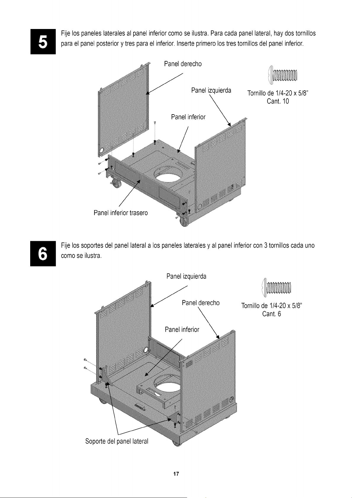
Fije los paneles laterales al panel inferior como se ilustra. Para cada panel lateral, hay dos tornillos
para el panel posterior y tres para el inferior. Inserte primero los tres tornillos del panel inferior.
Panel derecho
Panel izquierda
Tornillode 1/4-20 x 5/8"
Cant. 10
Panel inferior trasero
Fije los soportes del panel lateral a los paneles lateralesy al panel inferior con 3 tornillos cada uno
como se ilustra.
Panel izquierda
Panel derecho
Tornillode 1/4-20 x 5/8"
Cant. 6
Soporte del panel lateral
17
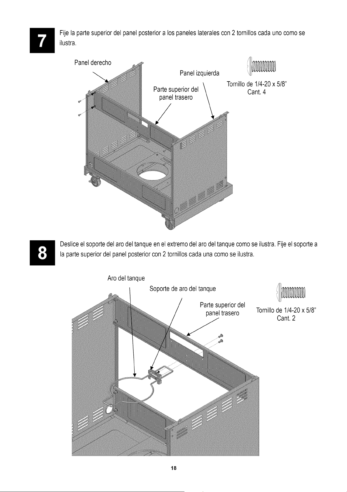
Fije la parte superior del panel posteriora los paneles laterales con 2 tornillos cada uno como se
ilustra.
Panel derecho
Panel izquierda
Parte superior del
panel trasero
Tornillode 1/4-20 x 5/8"
Cant. 4
Deslice el soporte del aro del tanque en el extremodel aro del tanque como se ilustra. Fije el soporte a
la parte superior del panel posteriorcon 2 tornillos cada una como se ilustra.
Aro del tanque
Soporte de aro del tanque
Parte superior del
panel trasero
Tomillo de 1/4-20 x 5/8"
Cant. 2
18
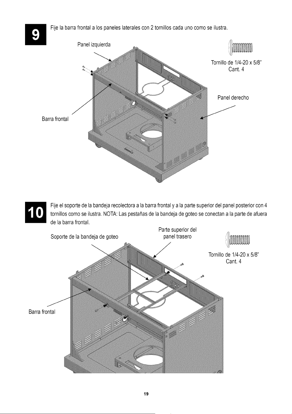
Fije la barra frontal a los paneles lateralescon 2 tornillos cada uno como se ilustra.
Panel izquierda iI _
Tornillode 1/4-20 x 5/8"
°_ Cant. 4
Panel derecho
Barra frontal
Fije el soporte de la bandeja recolectora a la barra frontal y a la partesuperior del panel posterior con 4
tornillos como se ilustra. NOTA: Las pesta_as de la bandeja de goteo se conectan a la parte de afuera
de la barra frontal.
Parte superior del
panel trasero
Soporte de la bandeja de goteo
i/I/
Tornillode 1/4-20 x 5/8"
Cant. 4
Barra frontal
19
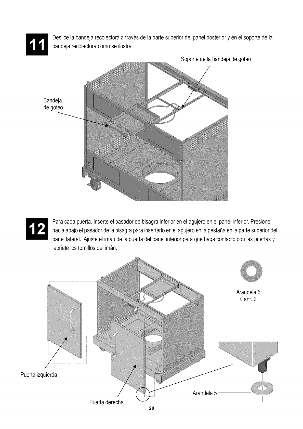
Deslice la bandeja recolectora a traves de la parte superior del panel posterioryen el soporte de la
bandeja recolectora como se ilustra.
Soporte de la bandeja de goteo
Bandeja
de goteo
Para cada puerta, inserte el pasadorde bisagra inferior en el agujero en el panel inferior. Presione
hacia abajo el pasador de la bisagra para insertarlo en el agujero en la pestaSaen la parte superior del
panel lateral. Ajuste el iman de la puerta del panel inferior para que haga contacto con las puertas y
apriete los tornillos del iman.
Puerta izquierda
Puerta derecha
20
Arandela 5
Arandela 5
Cant. 2
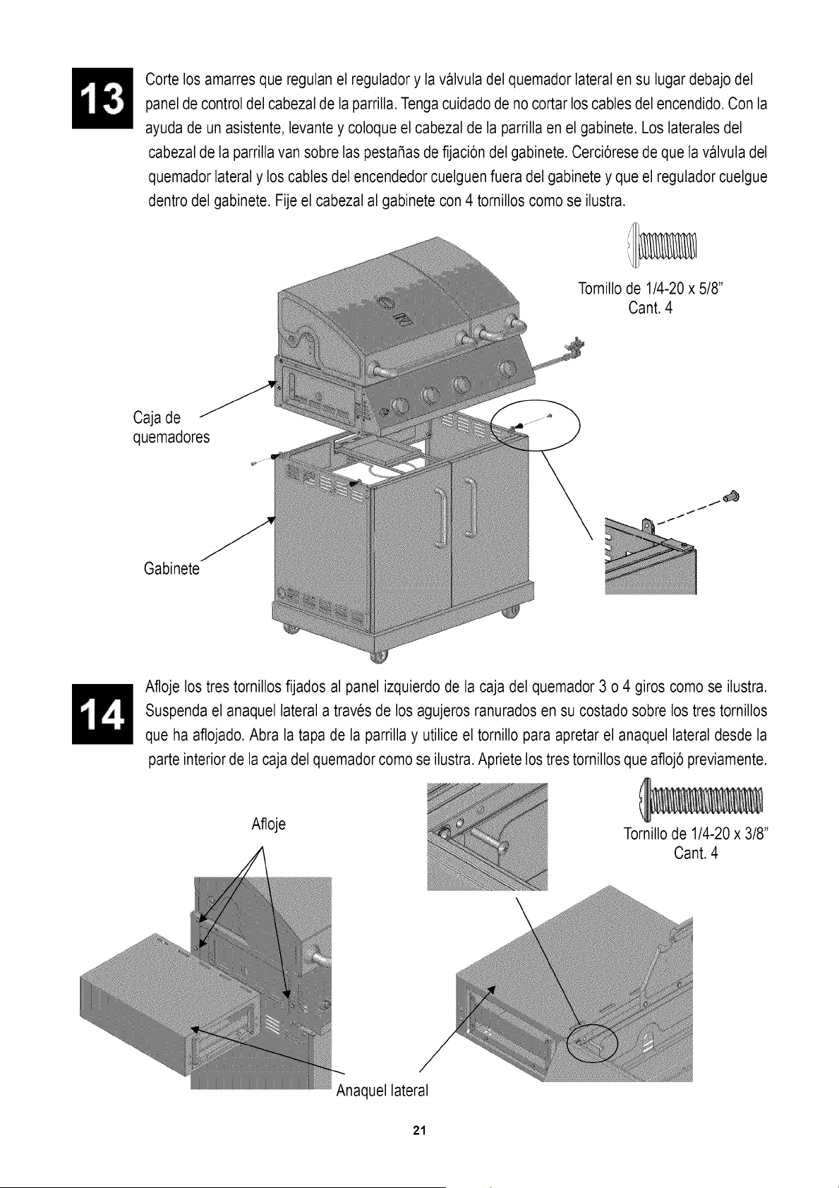
Cortelosamarresqueregulanelreguladory lavalvuladelquemadorlateralensulugardebajodel
paneldecontroldelcabezaldelaparrilla.Tengacuidadodenocortarloscablesdelencendido.Conla
ayudadeunasistente,levantey coloqueelcabezaldelaparrillaenelgabinete.Loslateralesdel
cabezaldelaparrillavansobrelaspesta_asdefijaci6ndelgabinete.Cerci6resedequelavalvuladel
quemadorlateraly loscablesdelencendedorcuelguenfueradelgabineteyqueel reguladorcuelgue
dentrodelgabinete.Fijeel cabezalal gabinetecon4 tornilloscomoseilustra.
Tornillo de 1/4-20 x 5/8"
Cant. 4
Caja de
quemadores
Gabinete
Afloje los tres tornillos fijados al panel izquierdo de la caja del quemador 3 o 4 giros como se ilustra.
Suspenda el anaquel lateral a traves de los agujeros ranurados en su costado sobre los tres tornillos
que ha aflojado.Abra la tapa de la parrilla y utilice el tornillo para apretar el anaquel lateral desde la
parte interior de la caja del quemadorcomo se ilustra.Apriete los tres tornillos que afloj6 previamente.
Afloje
Tornillode 1/4-20 x 3/8"
Cant. 4
Anaquel lateral
21

Hale el cuerpo de la gaveta hacia afuera.
Asegure el cabezal de la gaveta al cuerpo de la misma con 3 tornillos en cada lado como se ilustra.
Tornillode 5/32-32 x 1/2"
Cant. 6
Anaquel lateral
Cabezal de la
gaveta
Cuerpo de la
gaveta
Anaquel del quemador lateral
Afloje los cuatro tornillos fijados al panel derecho de la caja del quemador 3 o 4 giros como se ilustra.
Suspenda el anaquel del quemador lateral a traves de los agujeros ranurados en su costadosobre los
cuatro tornillos que ha aflojado. Abra la tapa de la parrilla y utilice el tornillo enico para apretar el
anaquel del quemador lateral desde la parte interior de la caja del quemador como se ilustra. Apriete
los cuatro tornillos que afloj6 previamente. Fije el abridor de botellas al anaquel quemador lateral con
2 tornillos como se ilustra.
Afloje
Tornillode3/16-24x IA"
Cant.2
Tornillode 1/4-20x 1-3/8"
Cant.1
Anaquel lateral de estufa
botellas
22
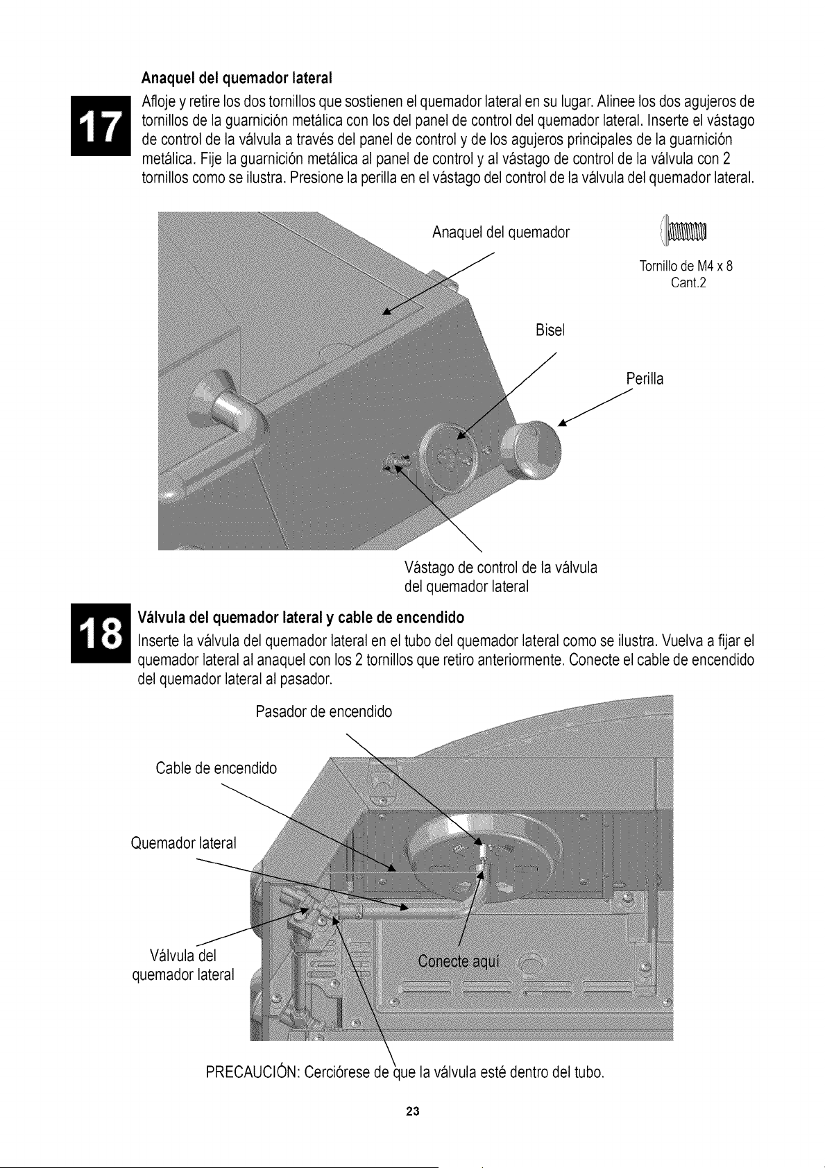
Anaquel del quemador lateral
Afloje y retire los dos tornillos quesostienen el quemadorlateral en su lugar.Alinee los dos agujeros de
tornillos de la guarnici6n metalica con los del panel de control del quemador lateral. Inserte el vastago
de control de la valvula a traves del panel de control y de los agujeros principales de la guarnici6n
metalica. Fije la guarnici6n metalica al panel de control y al vastago de control de la valvula con 2
tornillos como se ilustra. Presione la perilla en el vastago del control de la valvula del quemador lateral.
Anaquel del quemador
TornillodeM4x8
Cant.2
Bisel
Perilla
Vastago de control de la valvula
del quemador lateral
Valvula del quemador lateral y cable de encendido
Inserte la valvula del quemador lateral en el tubo del quemador lateral como se ilustra. Vuelva a fijar el
quemador lateral al anaquel con los 2 tornillos que retiro anteriormente. Conecte el cable de encendido
del quemador lateral al pasador.
Pasadorde encendido
Cable de encendido
Quemador lateral
Valvula del
quemador lateral
PRECAUCION:Cerci6rese de ue la valvula este dentro del tubo.
23
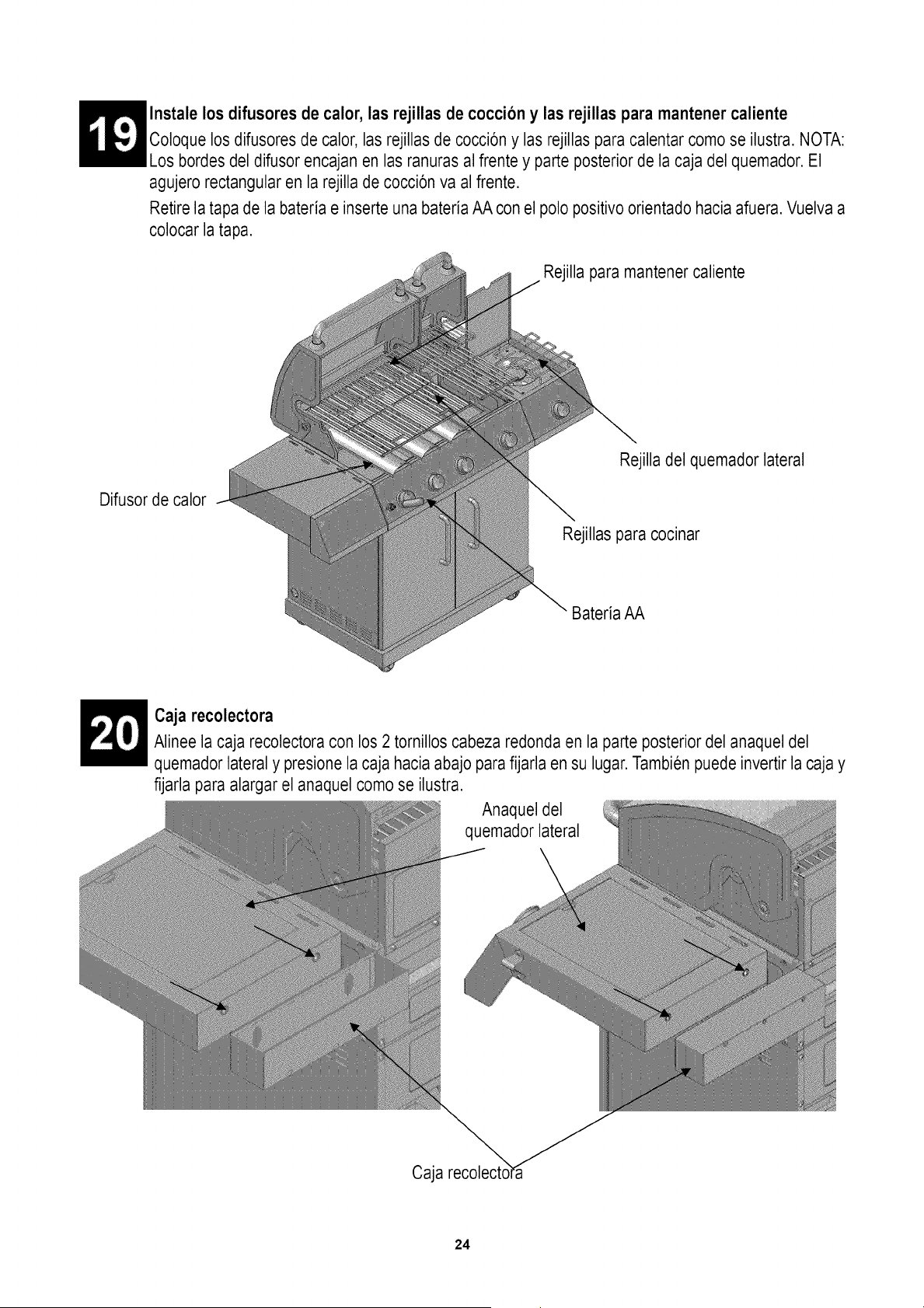
Instale los difusores de calor, las rejillas de coccion y las rejillas para mantener caliente
Coloque los difusores de calor, las rejillas de cocci6n y las rejillas para calentar como se ilustra. NOTA:
Los bordes del difusor encajan en las ranuras al frente y parte posterior de la caja del quemador.El
agujero rectangular en la rejilla de cocci6n va al frente.
Retire la tapa de la bateria e inserteuna bateria AA con el polo positivo orientado hacia afuera.Vuelva a
colocar la tapa.
Rejilla para mantener caliente
Difusor de calor
Rejilla del quemador lateral
Rejillas para cocinar
Bateria AA
Caja recolectora
Alinee la caja recolectora con los 2 tornillos cabeza redonda en la parte posterior del anaquel del
quemador lateral y presione la caja hacia abajo para fijarla en su lugar.Tambienpuede invertir la caja y
fijarla para alargar el anaquel como se ilustra.
Anaquel del
quemador lateral
Caja
24
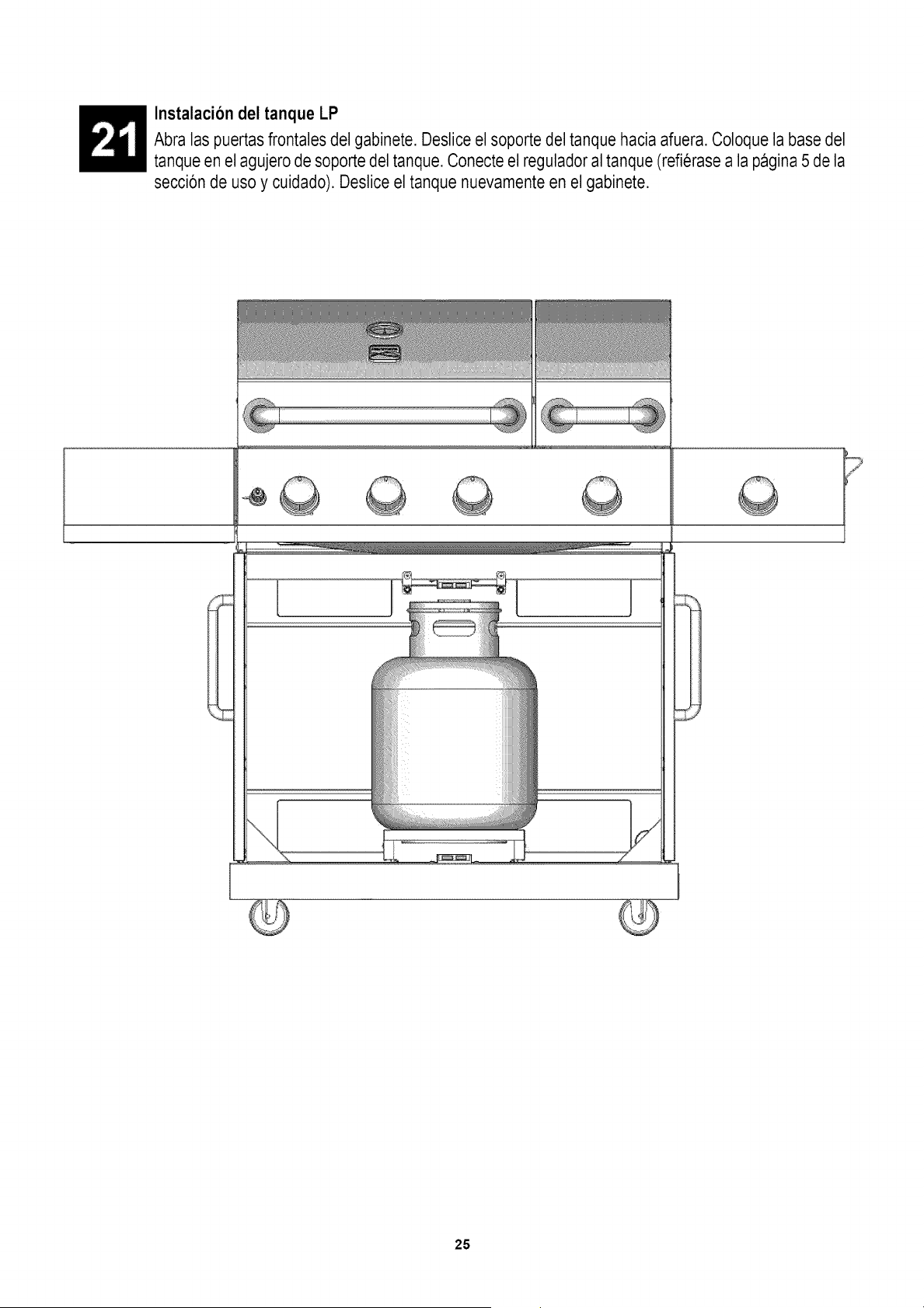
Instalacion del tanque LP
Abra las puertasfrontales del gabinete. Deslice el soporte del tanque hacia afuera. Coloque la base del
tanque en el agujero de soporte del tanque. Conecte el reguladoral tanque (refierase a la pagina 5 de la
secci6n de uso y cuidado). Deslice el tanque nuevamente en el gabinete.
@
©
25
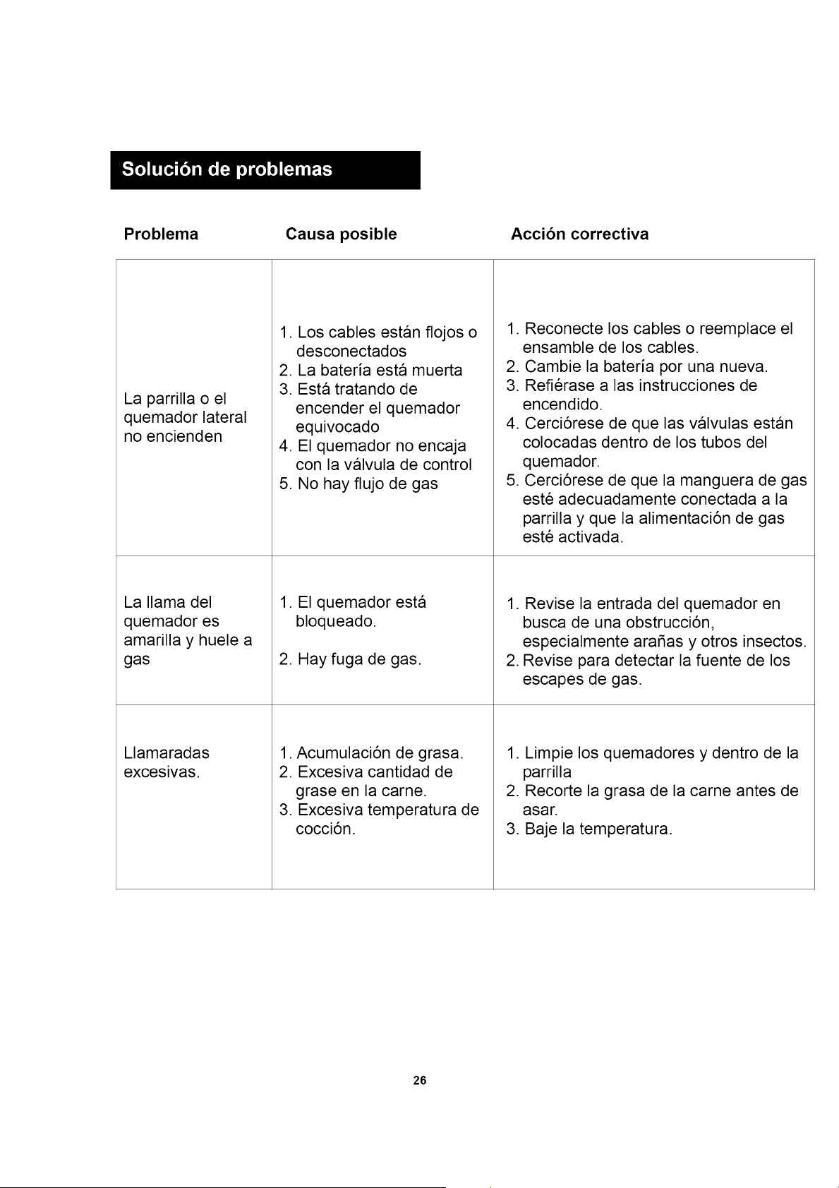
Problema
Causa posible
Accion correctiva
La parrilla o el
quemador lateral
no encienden
La llama del
quemador es
amarilla y huele a
gas
Llamaradas
excesivas.
1. Los cables estan flojos o
desconectados
2. La bateria esta muerta
3. Esta tratando de
encender el quemador
equivocado
4. El quemador no encaja
con la valvula de control
5. No hay flujo de gas
1. El quemador esta
bloqueado.
2. Hay fuga de gas.
1. Acumulaci6n de grasa.
2. Excesiva cantidad de
grase en la came.
3. Excesiva temperatura de
cocci6n.
1. Reconecte los cables o reemplace el
ensamble de los cables.
2. Cambie la bateria por una nueva.
3. Refierase alas instrucciones de
encendido.
4. Cerci6rese de que las valvulas estan
colocadas dentro de los tubos del
quemador.
5. Cerci6rese de que la manguera de gas
este adecuadamente conectada a la
parrilla y que la alimentaci6n de gas
este activada.
1. Revise la entrada del quemador en
busca de una obstrucci6n,
especialmente arafias y otros insectos.
2. Revise para detectar la fuente de los
escapes de gas.
1. Limpie los quemadores y dentro de la
parrilla
2. Recorte la grasa de la carne antes de
asar.
3. Baje la temperatura.
26
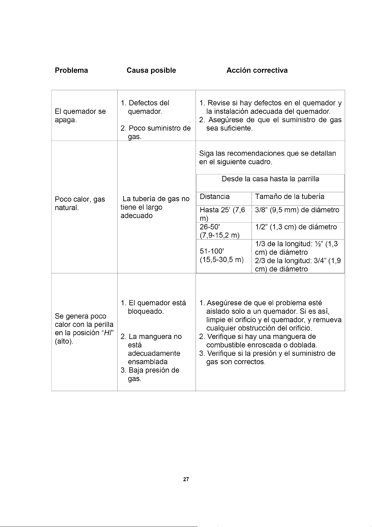
Problema
Causa posible
Accion correctiva
El quemador se
apaga.
Poco calor, gas
natural.
Se genera poco
calor con la perilla
en la posici6n "HI"
(alto).
1. Defectos del
quemador.
2. Poco suministro de
gas.
La tuberia de gas no
tiene el largo
adecuado
1. El quemador esta
bloqueado.
2. La manguera no
esta
adecuadamente
ensamblada
3. Baja presi6n de
gas.
1. Revise si hay defectos en el quemador y
la instalaci6n adecuada del quemador.
2. AsegOrese de que el suministro de gas
sea suficiente.
Siga las recomendaciones que se detallan
en el siguiente cuadro.
Desde la casa hasta la parrilla
Distancia Tama_o de la tuberia
Hasta 25' (7,6 3/8" (9,5 mm) de diametro
m)
26-50' 1/2" (1,3 cm) de diametro
(7,9-15,2 m)
51-100'
(15,5-30,5 m)
1/3 de la Iongitud: ½" (1,3
cm) de diametro
2/3 de la Iongitud: 3/4" (1,9
cm) de diametro
1. AsegOrese de que el problema este
aislado solo a un quemador. Si es asi,
limpie el orificio y el quemador, y remueva
cualquier obstrucci6n del orificio.
2. Verifique si hay una manguera de
combustible enroscada o doblada.
3. Verifique si la presi6n y el suministro de
gas son correctos.
27
Su hogar
Para experta soluci6n de problemas y consejos practicos para el hogar:
Administracibn de mi hogar
www.managemyhome.com
Para reparaci6n - en su hogar - de todos los equipos grandes de marca, equipos de
cesped y jardin o para sistemas de calefacci6n o aire acondicionado,
iindependientemente de quien los haya fabricado, independientemente de
quien los venda!
Para piezas de repuesto, accesorios y manuales del propietario que necesite para
hacerlo usted mismo.
Para instalaci6n profesional de Sears o artefactos para el hogar y articulos tales como
abridores de puertas y calentadores de agua.
1-800-4-MY-HOME ®(1-800-469-4663)
Llame de dia o de noche (EE.UU. y Canada)
www.sears.com www.sears.ca
Su hogar
Para reparaci6n de articulos como aspiradoras, equipos de cesped y electr6nicos,
Ilame a cualquier hora para encontrar la ubicaci6n mas cercana de un Centro de
Servicio de Piezas y Reparaci6n de Sears.
1-800-482-0131 (EE.UU.) 1-800-482-0131 (Canada)
www.sears.com www.sears.ca
Para adquirir un acuerdo de protecci6n sobre un producto al cual Sears presta servicio:
1-800-827-6655 (EE.UU.) 1-800-361-6665 (Canad_l)
Para pedir semicio de reparaci6n
a domicilio, y para ordenar piezas:
1-888-SU-HOGAR _
Au Canada pour service en fran£ais:
1-800-LE-FOYER Mc
(1-800-533-6937)
www.sears.ca
® Registered Trademark _ :Trademark / Se_ice Mark of Sears Brands;, LLC
® Marca R_istrada / tM Marca de Fabdca / SM Marca de Servicie de Sears Brands LLC
_,_cMarque de commerce / #p Marque dep_ee de Seats Brands_ LLC
28
® Sears Brands LLC