
Loading ...
Loading ...
Loading ...
– 14 –
10. OPERATION
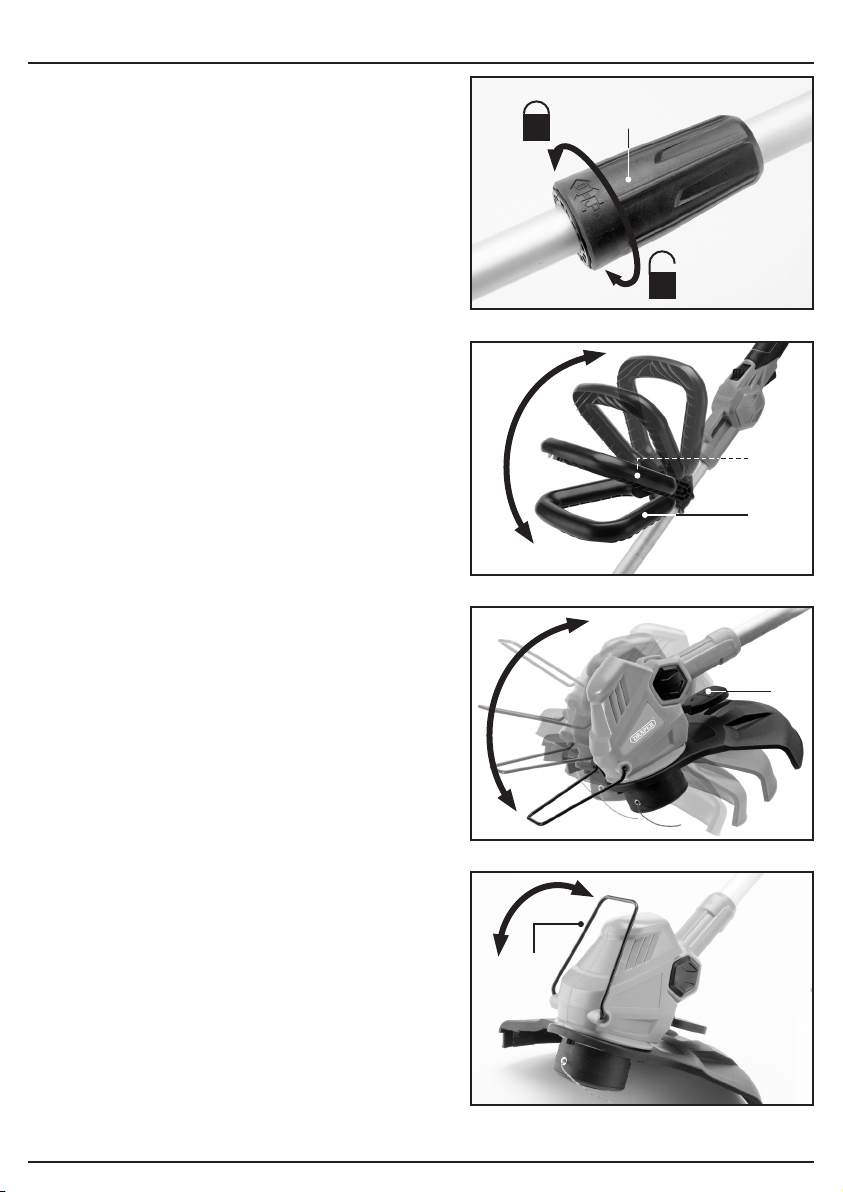
10.1 TOOL CONNECTOR – FIG.9
− Ensure the tool connector (4)is locked in place
prior to using the machine.
10.2 AUXILIARY HANDLE
ADJUSTMENT – FIG.12
− Unscrew the auxiliary locking (5.2)bolt.
− Adjust the auxiliary handle (5)to the most
comfortable working position.
− Re-tighten the auxiliary locking bolt.
10.3 HEAD ANGLE ADJUSTMENT –
FIG.13
The cutting head can be adjusted to four different
angles for ease of cutting.
− Whilst holding the shaft, push and hold the
cutting head angle adjustment lever (8).
− Rotate the head to the desired angle and
release the button. The head will lock at the
closest of the four set angles.
10.4 EDGE GUARD – FIG.14
The trimmer is fitted with an edge guard (2)that
can be raised or lowered, as required .
9
10
FIG.
FIG.
11
12
FIG.
FIG.
(4)
(5.2)
(5)
(8)
(2)
Loading ...
Loading ...
Loading ...