
Loading ...
Loading ...
Loading ...
– 11 –
8. ASSEMBLY
1
2
FIG.
FIG.
3
4
FIG.
FIG.
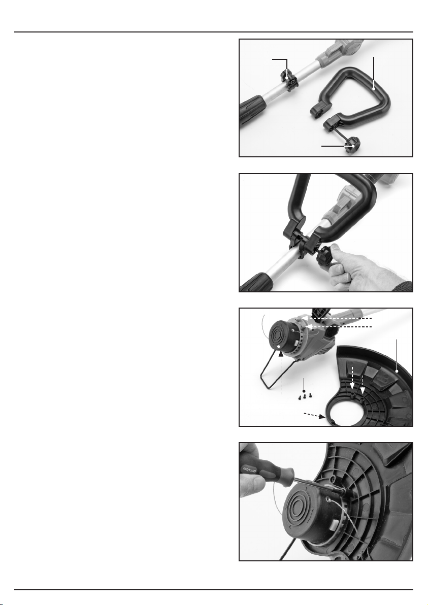
8.1 ATTACH THE AUXILIARY
HANDLE – FIGS.1 – 2
− Align the auxiliary handle (5) with the bracket
(5.1) mounted on the handle shaft.
− Thread the auxiliary handle locking bolt (5.2)
into the hole in the auxiliary handle and tighten.
8.2 ATTACH THE SAFETY GUARD –
FIGS.3 – 4
− Locate the safety guard (9)with the cutting
head so that the three holes on the guard (A),
align with the three holes on the cutting head
(B).
− With an appropriate cross-slot screwdriver,
tighten the two sections together using the
supplied screws (9.1).
(5.2)
(B)
(B)
(A)
(B)
(A)
(A)
(5.1)
(5)
(9)
(9.1)
Loading ...
Loading ...
Loading ...