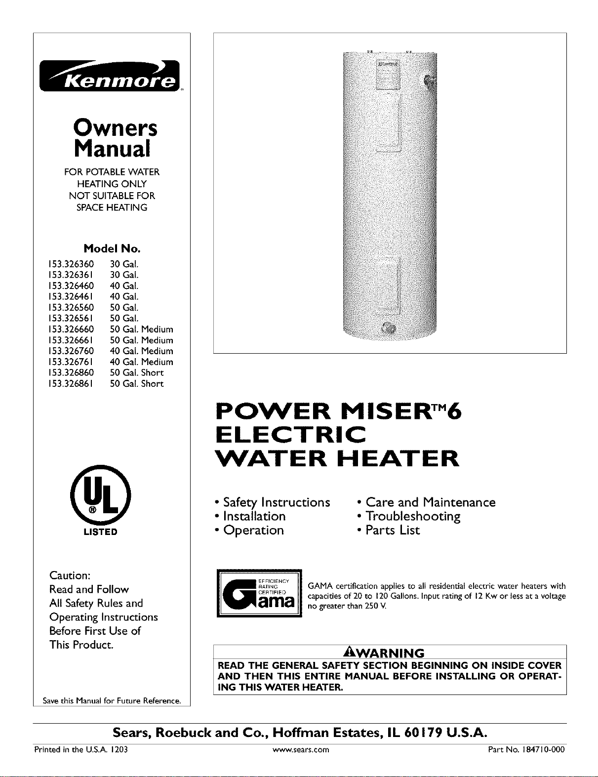
Owners
Manual
FOR POTABLEWATER
HEATING ONLY
NOT SUITABLEFOR
SPACEHEATING
Model No.
153.326360 30 Gal.
153.326361 30 Gal.
153.326460 40 Gal.
153.326461 40 Gal.
153.326560 50 Gal.
153.326561 50 Gal.
153.326660 50 Gal. Medium
153.326661 50 Gal. Medium
153.326760 40 Gal. Medium
153.326761 40 Gal. Medium
153.326860 50 Gal.Short
153.326861 50 Gal.Short
LISTED
Caution:
Read and Follow
All Safety Rules and
Operating Instructions
Before First Use of
This Product,
Savethis Manual for Future Reference.
POWER MISERTM6
ELECTRIC
WATER HEATER
•Safety Instructions
•Installation
• Operation
• Care and Maintenance
• Troubleshooting
• Parts List
GAMA certification appliesto all residential electric water heaters with
capacitiesof 20 to 120Gallons. Inputrating of 12Kw or lessat a voltage
no greater than 250 _L
_WARNING
READ THE GENERAL SAFETY SECTION BEGINNING ON INSIDE COVER
AND THEN THIS ENTIRE MANUAL BEFORE INSTALLING OR OPERAT-
ING THIS WATER HEATER.
Sears, Roebuck and Co., Hoffman Estates, IL 60179 U.S.A.
Printed in the U.S.A. 1203 www.sears.com Part No. 184710_0OO
Safety Precautions
_,WARNING J
Improper installation, adjustment, alteration, service or
maintenancecan causeDEATH, SERIOUSBODILY INJURY,J
OR PROPERTY DAMAGE. Refer to this manual for assis-
tance or consult your localSearsServiceCenter for further
information.
_WARNING
At the time of manufacture this water heater was provided
with acombination temperature*pressures relief valve certi-
fied by anationally recognized testing laboratory that main-
tains periodic inspection of production of listed equipment or
materials, as meeting the requirements for Relief Valves and
Automatic Gas Shutoff Devices for Hot Water Supply
Systems, and the current edition of ANSI Z21.22 • CSA 4.4
and the code requirements of ASME. If replaced, the valve
must meet the requirements of local codes, but not lessthan a
combination temperature and pressure relief valve certified as
meeting the requirements for Relief Valves and Automatic
Gas Shutoff Devices for Hot Water Supply Systems, ANSI
Z21.22 • CSA 4.4 by a nationally recognized testing laboratory
that maintains periodic inspection of production of listed
equipment or materials.
The valve must be marked with a maximum set pressure not
to exceed the marked hydrostatic working pressure of the
water heater (150 Ibs. p.s.i.) and a dischargecapacity not less
than the water heater input rate asshown on the model rating
plate. (Electric heaters -watts divided by 1000 x 3412 equal
BTU/Hr. rate.)
Your local jurisdictional authority, while mandating the use of
a temperature-pressure relief valve complying with ANSI
Z21.22 •CSA 4.4 and ASME, may require a valve model differ-
ent from the one furnishedwith the water heater.
Compliance with such local requirements must be satisfied by
the installer or end user of the water heater with alocally
wescribed temperature-pressure relief valve installed in the
designated opening in the water heater in place of the factory
furnishedvalve.
For safe operation of the water heater, the relief valve must
not be removed from it's designated opening or plugged.
The temperature-pressure relief valve must be installed
directly into the fitting of the water heater designated for the
relief valve. Positionthe valve downward and provide tubing so
that any discharge will exit only within 6 inches above, or at
any distance below the structural floor. Be certain that nocon-
tact is made with any live electrical part. The discharge open-
ing must not be blocked or reduced in size under any circum-
stances. Excessive length, over 30 feet, or use of more than
four elbows can cause restriction and reduce the discharge
capacity of the valve.
No valve or other obstruction is to be placed between the
relief valve and the tank. Do not connect tubing directly to dis-
charge drain unlessa 6" air gap isprovided. To prevent bodily
injury, hazard to life, or property damage, the relief valve must
be allowed to discharge water in quantities should circum-
stances demand. If the discharge pipe is not connected to a
drain or other suitable means, the water flow may causeprep-
erty damage.
The Discharge Pipe:
• Must not be smaller in size than the outlet pipe size of the
valve, or haveany reducing couplingsor other restrictions.
•Must not be pluggedor blocked.
•Must be of material listed for hot water distribution.
•Must be installed so as to allow complete drainage of both
the temperature-pressure relief valve, and the discharge
pipe.
•Must terminate at an adequate drain.
•Must not have anyvalve between the relief valve and tank.
_,WARNING J
HAZARD OF ELECTRICAL SHOCK! Before removing
any access panels or servicing the water heater, make J
sure the electrical supply to the water heater isturned
"OFF". Failure to do this could result in DEATH, SERI-
OUS BOD LY NJURY,OR PROPERTY DAMAGE.
AWARNING
HOTTER WATER CAN SCALD: Water heaters are
intended to produce hot water. Water heated to a tem-
perature whichwill satisfyspaceheating,clotheswashing,
dish washing, and other sanitizing needs can scald and
_ermanently injure you upon contact. Some people are
more likelyto be permanently injured by hot water than
others. These includethe elderly,children, the infirm, or
physically/mentally handicapped. If anyone using hot
water in your home fits into one of these groups or if
there isa localcode or state law requiring a certain tem-
perature water at the hot water tap, then you must take
specialprecautions.In addition to using the lowest possi-
ble temperature setting that satisfies your hot water
needs, ameans such as a mixing valve, shallbe used at
the hot water taps used by these people or at the water
heater. Mixing valvesare available at plumbing supplyor
hardware stores. Follow manufacturers instructions for
installationofthe valves.Before changingthe factory set-
ting on the thermostat, read the "Temperature
Regulation"sectionin this manual.
&WARNING
WATER HEATERS EQUIPPED FOR ONE VOLTAGE
ONLY: This water heater isequipped for one type voltage
only. Check the rating plate near the bottom access panel
for the correct voltage. DO NOT use this water heater
with any voltage other than the one shown on the model
rating plate. Failure to use the correct voltage can cause
problems which can result in DEATH, SERIOUS BODILY
INJURY, OR PROPERTY DAMAGE. If you have any ques-
tions or doubts consult your electric company.
2
&WARNING
INSULATING JACKETS: When installing an external
water heater insulation jacket on an electric water
heater:
a. DO NOT cover the temperature-pressure relief valve.
b. DO NOT put insulation over the access covers or any
access areas.
c. DO NOT remove operating instructions, and safety
related warning labels and materials affixed to the water
heater.
d. DO obtain new warning and instruction labels from
Sears for placement on the jacket directly over the exist-
in_ labels.
_,WARNING J
Do not usethis applianceif anypart of it hasbeen under J
water. An electrical short or malfunction could occur.The
water heater shoudbe rep aced.
CAUTION
WATER HEATERS EVENTUALLY LEAK: Installation of
the water heater must be accomplished in such a manner
that if the tank or any connections should leak, the flow of
water will not cause damage to the structure. When such
locations cannot be avoided, a suitable drain pan should
be installed under the water heater. Drain pans are avail-
able at your local Sears Store. Such a drain pan must be
piped to an adequate drain.
Table of Contents
Safety Precautions ...............................................................................................................................................2
Table of Contents ................................................................................................................................................3
Customer Responsibilities .......................................................................................................................4
Product Specifications ..................................................................................................................................4
Preparing for the New Installation .............................................................................................4
Materials and Basic Tools Needed ...............................................................................................5
Materials Needed ...................................................................................................................................................................... 5
Basic *Ibols................................................................................................................................................................................ 5
Installation Instructions ........................................................................................................................6-15
Removing the Old Water Heater. ............................................................................................................................................ .6
Facts to Consider About the Location ..................................................................................................................................... .7
Facts to Consider About the Convertible Element ................................................................................................................... .7
Water Piping ............................................................................................................................................................................ .8
T&P Valve and Pipe Insulation .............................................................................................................................................. .8
_l_mperature-Pressure Relief Valve ............................................................................................................................................ .9
Filling the Water Heater .......................................................................................................................................................... l0
Converting the Lower Element ......................................................................................................................................... 10-12
Wiring Diagrams .................................................................................................................................................................... 13
Wiring .................................................................................................................................................................................... 14
Installation Checklist .............................................................................................................................................................. 15
Service and Adjustment ......................................................................................................................16-20
_l_mperature Regulation .......................................................................................................................................................... 16
Thermostats ............................................................................................................................................................................ 16
Thermostat Settings ................................................................................................................................................................ 16
Upper Thermostat Adjustment ............................................................................................................................................... 16
Lower Tbennostat Adjustment ............................................................................................................................................... 17
_l_mperature-Pressure Relief Valve Operation .......................................................................................................................... 17
Draining ................................................................................................................................................................................. 17
Element Cleaning and Replacement ................................................................................................................................. 18-20
Anode Rod Inspection ........................................................................................................................................................... .20
Drain Valve Washer Replacement .......................................................................................................................................... .20
Service ................................................................................................................................................................................... .20
Troubleshooting Guide ........................................................................................................................21-24
Start Up Conditions .............................................................................................................................................................. 21
Thermal Expansion .............................................................................................................................................................. 21
Strange Soun& .................................................................................................................................................................... 21
Operational Conditions ..................................................................................................................................................... 22-23
Smelly Water ........................................................................................................................................................................ 22
Air in Hot Water Faucets ..................................................................................................................................................... 22
Rmnbling Noise ................................................................................................................................................................... 22
High "Ihnperature Shut OffSystem ................................................................................................................................ 22-23
Not Enough Hot Water ........................................................................................................................................................ 23
Water is "Ibo Hot .................................................................................................................................................................. 23
Leakage Checkpoints ............................................................................................................................................................. 24
Parts Order List...............................................................................................................................................26-31
Warranty ........................................................................................................................................................................32
3
Customer Responsibilities
Thank You for purchasing a Sears water heater.
Properly installed and maintained, it should give you years of
trouble free service. If you should decide that you want the new
water heater professionally installed, contact the local Sears
Service Center or any Sears store. They will arrange for prompt,
quality installation by Sears authorized contractors.
Abbreviations Found In This Instruction Manual
U.L. - UnderwritersLaboratories Inc.
NEC - National ElectricalCode
ANSI -American National Standards Institute
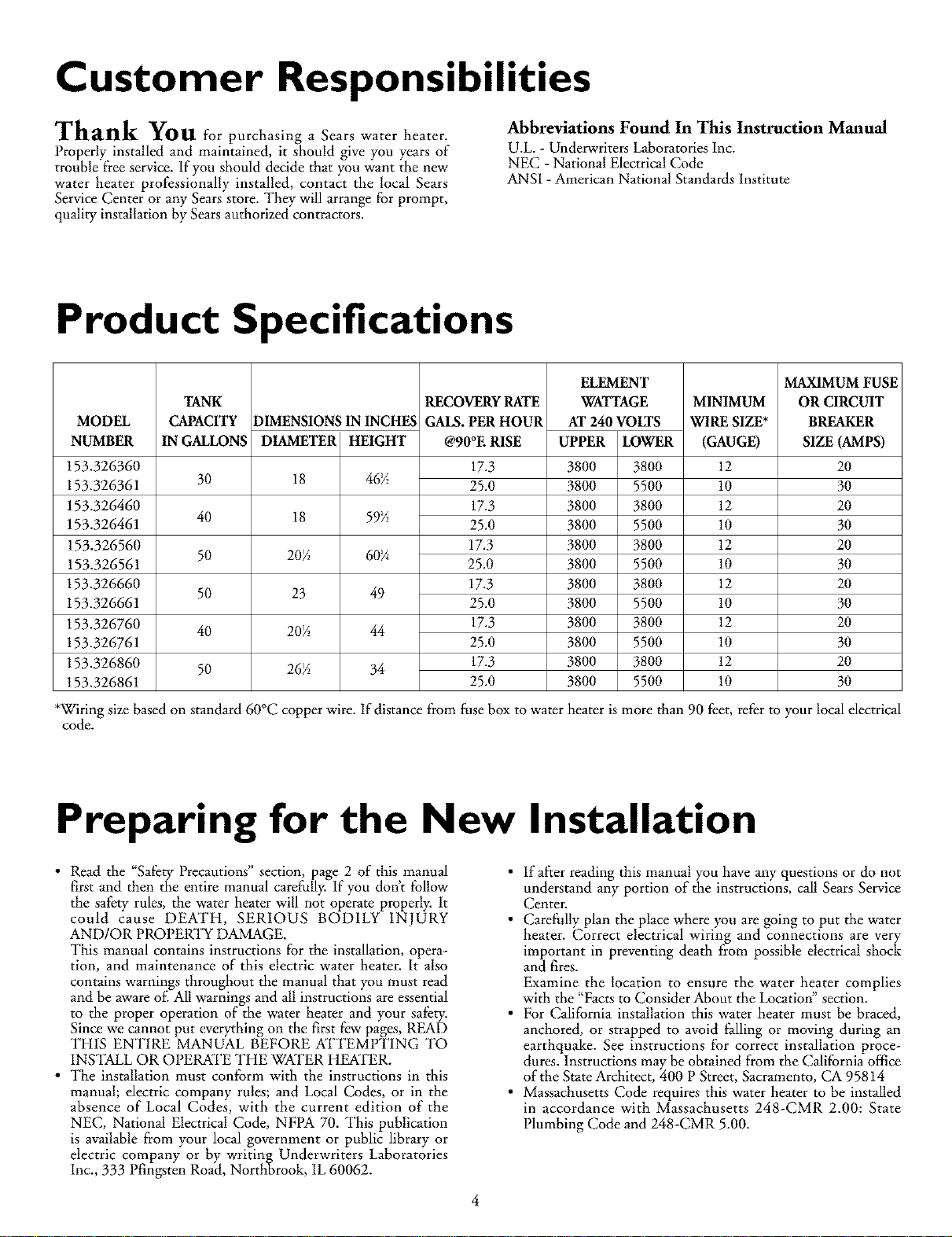
Product Specifications
MODEL
NUMBER
153.326360
153.326361
153.326460
153.326461
153.326560
153.326561
153.326660
153.326661
153.326760
153.326761
153.326860
153.326861
TANK
CAPACITY
IN GALLONS
30
40
50
50
40
50
DIMENSIONSIN INCHES
DIAMETER HEIGHT
18 46½
18 59½
20½ 60¼
23 49
20½ 44
26½ 34
RECOVERYRATE
GALS.PER HOUR
@90°E RISE
17.3
25.0
17.3
25.0
17.3
25.0
17.3
25.0
17.3
25.0
17.3
25.0
ELEMENT
WATTAGE
AT 240 VOLTS
UPPER IDWER
3800 3800
3800 5500
3800 3800
3800 5500
3800 3800
38OO 55OO
3800 3800
38OO 55OO
3800 3800
38OO 55OO
3800 3800
38OO 55OO
MINIMUM
WIRE SIZE*
(GAUGE)
12
10
12
10
12
10
12
10
12
10
12
10
MAXIMUM FUSE
OR CIRCUIT
BREAKER
SIZE (AMPS)
20
30
20
30
20
30
2O
3O
2O
3O
2O
3O
*W_lringsize based on standard60°C copper wire. If distance from fuse box to water heater is morn than 90 _et, m_r to your local elec_ical
code.
Preparing for the New Installation
•Read the "Safety Precautions" section, page 2 of this manual
first and then the entire manual carefully. If you don't tbllow
the safety rules, the water heater will not operate properly. It
could cause DEATH, SERIOUS BODILY INJURY
AND/OR PROPERLY?DAMAGE.
This manual contains instructions for the installation, opera-
tion, and maintenance of this electric water heater. It also
contains warnings throughout the manual that you must read
and be aware of'. All warnings and all instructions are essential
to the proper operation of the water heater and your safety.
Since we cannot put everything on the first few pages, READ
THIS ENTIRE MANUAL BEFORE KFFEMPT1NG TO
INSTALL OR OPERKFE THE WATER HEATER.
• The installation must conform with the instructions in this
manual; electric company rules; and Local Codes, or in the
absence of Local Codes, with the current edition of the
NEC, National Electrical Code, NFPA 70. This publication
is available from your local government or public library or
electric company or by writing Underwriters Laboratories
Inc., 333 Pfingsten Road, Northbrook, IL 60062.
• If after reading this manual you have any questions or do not
understand any portion of the instructions, call Sears Service
Center.
• Carefully plan the place where you are going to put the water
heater. Correct electrical wiring and connections are very
important in preventing death from possible electrical shock
and fires.
Examine the location to ensure the water heater complies
with the "Facts to Consider About the Location" section.
• For California installation this water heater must be braced,
anchored, or strapped to avoid falling or moving during an
earthquake. See instructions for correct installation proce-
dures. Instructions may be obtained from the California office
of the State Architect, 400 P Street, Sacramento, CA 95814
• Massachusetts Code requires this water heater to be installed
in accordance with Massachusetts 248-CMR 2.00: State
Plumbing Code and 248-CMR 5.00.
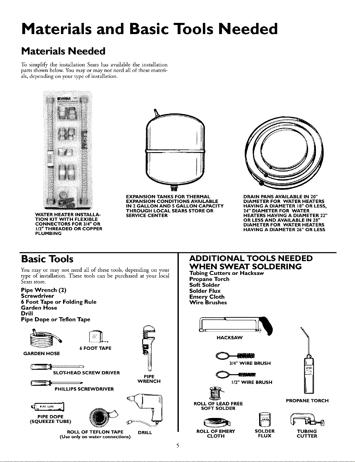
Materials and Basic Tools Needed
Materials Needed
_lb simplify the installation Sears has available the installation
parts shown below. You may or may not need all of these materi-
als, depending on your type of installation.
WATER HEATER INSTALLA.
TION KIT WITH FLEXIBLE
CONNECTORS FOR 3/4" OR
1/2" THREADED OR COPPER
PLUMBING
EXPANSION TANKS FOR THERMAL
EXPANSION CONDITIONS AVAILABLE
IN 2 GALLON AND 5 GALLON CAPACITY
THROUGH LOCAL SEARS STORE OR
SERVICE CENTER
DRAIN PANS AVAILABLE IN 20"
DIAMETER FOR WATER HEATERS
HAVING A DIAMETER 18" OR LESS,
24" DIAMETER FOR WATER
HEATERS HAVING A DIAMETER 22"
OR LESS AND AVAILABLE IN 20"
DIAMETER FOR WATER HEATERS
HAVING A DIAMETER 26" OR LESS
Basic Tools
You may or may not need all of these tools, depending on your
type of installation. These tools can be purchased at your local
Sears store,
Pipe Wrench (2)
Screwdriver
6Foot Tape or Folding Rule
Garden Hose
Drill
Pipe Dope or Teflon Tape
6FOOT TAPE
GARDEN HOSE
SLOT_HEAD SCREW DRIVER
PHILLIPS SCREWDRIVER
PIPE
WRENCH
PIPE DOPE
(SQUEEZE TUBE)
ROLL OF TEFLON TAPE DRILL
(Use only on water connections)
ADDITIONAL TOOLS NEEDED
WHEN SWEAT SOLDERING
Tubing Cutters or Hacksaw
Propane Torch
Soft Solder
Solder Flux
Emery Cloth
Wire Brushes
HACKSAW
3/4" WIRE BRUSH
I/2" WIRE BRUSH
PROPANE TORCH
ROLL OF LEAD FREE
SOFT SOLDER
ROLL OF EMERY SOLDER TUBING
CLOTH FLUX CUTTER
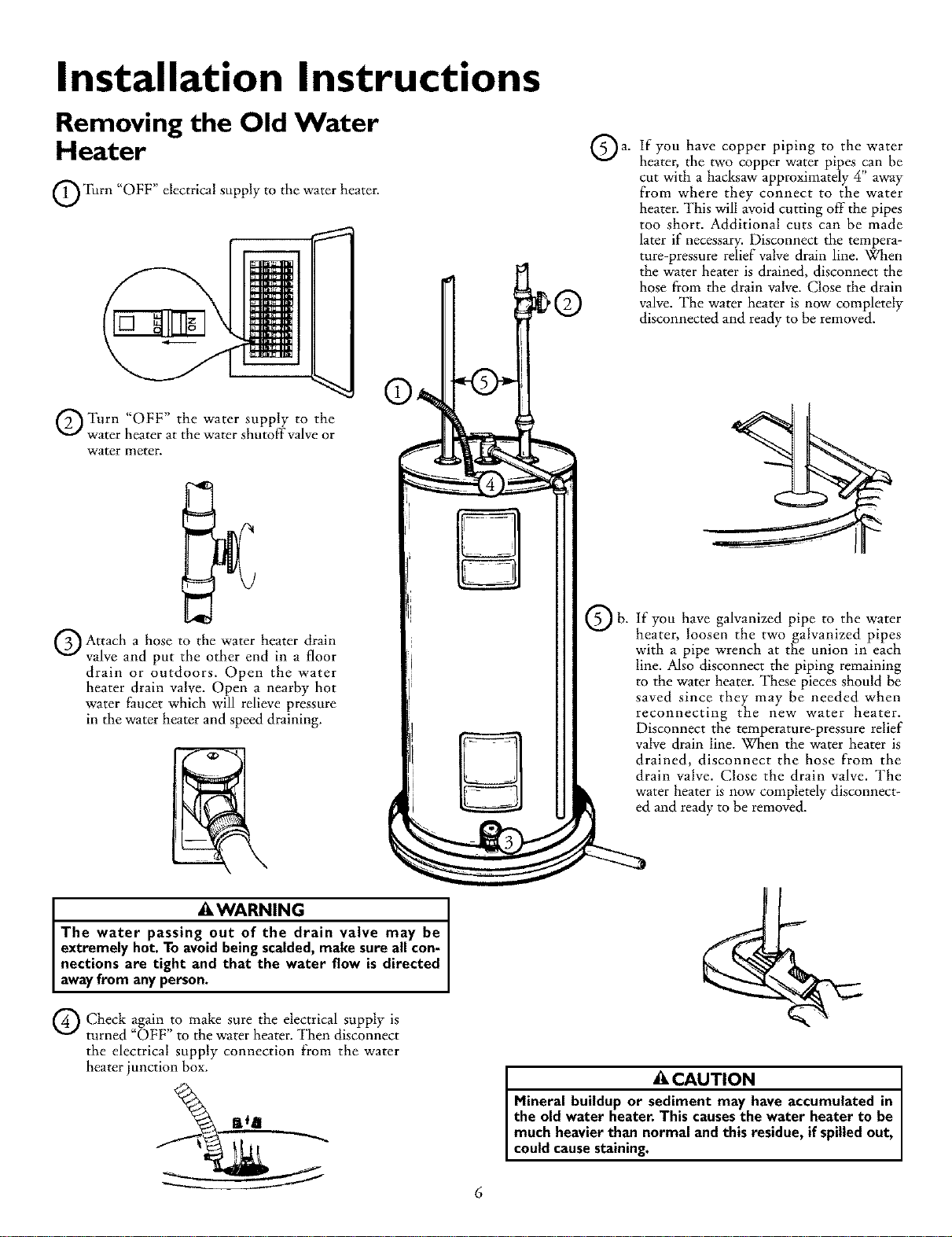
Installation Instructions
Removing the Old Water
Heater
O_(i_rn "OFF" electrical supply to the water heater.
]
QTurn "OFF" the water supply to the
water heater at the water shutoffvalve or
water meter.
Q Attach a hose to the water heater drain
valve and put the other end in a floor
drain or outdoors. Open the water
heater drain valve. Open a nearby hot
water faucet which will relieve pressure
in the water heater and speed draining.
a,
Qb.
If you have copper piping to the water
heater, the two copper water pipes can be
cut with a hacksaw approximately 4" away
from where they connect to the water
heater. This will avoid cutting off the pipes
too short. Additional cuts can be made
later if necessary. Disconnect the tempera-
ture-pressure relief valve drain line. When
the water heater is drained, disconnect the
hose from the drain valve. Close the drain
valve. The water heater is now completely
disconnected and ready to be removed.
If you have galvanized pipe to the water
heater, loosen the two galvanized pipes
with a pipe wrench at the union in each
line. Also disconnect the piping remaining
to the water heater. These pieces should be
saved since they may be needed when
reconnecting the new water heater.
Disconnect the temperature-pressure relief
valve drain line. When the water heater is
drained, disconnect the hose from the
drain valve. Close the drain valve. The
water heater is now completely disconnect-
ed and ready to be removed.
AWARNING
The water passing out of the drain valve may be
extremely hot. To avoidbeingscalded,make sure all con-
nections are tight and that the water flow is directed
awayfrom anyperson.
Q Check again to make sure the electrical supply is
turned "OFF" to the water heater. Then disconnect
the electrical supply connection from the water
heater junction box. CAUTION
Mineral buildup or sediment may have accumulated in
the old water heater. This causesthe water heater to be
much heavierthan normal and this residue,if spilledout,
could causestaining.
6
Installation Instructions (cont'd)
Facts to Consider About the
Location Facts to Consider About the
Convertible Lower Element
You should carefully choose an indoor location for the new water
heater, because the placement is a very important consideration
for the safety of the occupants in the building and for the most
economical use of the appliance. This water heater is not intend-
ed for outdoor installation.
Whether replacing an old water heater or putting the water
heater in a new location, the following critical points must be
observed.
•The location selected should be indoors asclose to and as cen-
tralized with the water piping system as possible. This water
heater, aswell as all water heaters, will eventually leak. Do not
install without adequate drainage provisions where water flow
will cause damage.
ACAUTION
WATER HEATERS EVENTUALLY LEAK: Installation of
the water heater must be accomplished in sucha man-
ner that if the tank or any connectionsshouldleak, the
flow of water will not cause damage to the structure.
When suchlocationscannot be avoided,a suitable drain
pan should be installed under the water heater. Drain
pansare availableat your local Searsstores.Sucha drain
pan must be pipedto anadequatedrain.
The Upper Element (if a double element model), is a conven-
tional 3800 watt element which only operates at its rated
wattage on 240 volts. (See rating plate on water heater).
The Lower Element of the water heater can be converted from
operation at 3800 watts to 5500 watts on a 240 volt system.
Read and follow water heater warnings and instructions.If after
reading these instructions in this manual, if you do not under-
stand any portion, call Sears Service Center.
AWARNING
Before making the conversion to 5500 watts, check the
(I) power supply...must be 240 volts, (2) wiring...10
gauge AWG, Type TW, 60°C or equivalent, and (3)
Circuit breakers or fusing...capable of 30 amp loading.
Also, the installation must conform with this manual,
local codes and electric utility rules. Failure to comply
can result in DEATH, SERIOUS BODILY INJURY, OR
PROPERTY DAMAGE.
CAUTION I
INSTALLATION IN RESIDENTIAL GARAGES: The
water heater must be located and/or protected so it is
not subjectto physicaldamage bya movingvehicle.
• The location selection must provide adequate clearances for
servicing and proper operation of the water heater.
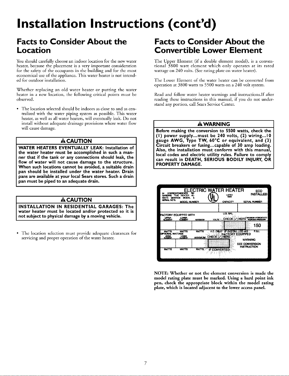
NOTE: Whether or not the element conversion is made the
model rating plate must be marked. Using a hard point ink
pen, check the appropriate block within the model rating
plate, which is located adjacent to the lower access panel.
Installation Instructions (cont'd)
Water Piping
*A WARNING
HOTTER WATER CAN SCALD: Water heaters are
intended to produce hot water. Water heated to a tem-
perature whichwill satisfyspaceheating,clotheswashing,
dish washing, and other sanitizing needs can scald and
_ermanently injure you upon contact. Some people are
more likelyto be permanently injured by hot water than
others. These includethe elderly,children, the infirm, or
physically/mentally handicapped. If anyone using hot
water in your home fits into one of these groups or if
there isa localcode or state law requiring a certain tem-
perature water at the hot water tap, then you must take
specialprecautions.In addition to using the lowest possi-
ble temperature setting that satisfies your hot water
needs,a means such as a mixing valve, shallbe used at
the hot water taps used by these people or at the water
heater. Mixing valvesare available at plumbing supplyor
hardware stores. Follow manufacturers instructions for
installationofthe valves.Before changingthe factory set-
ring on the thermostat, read the "Temperature
Regulation"sectionin this manual.
HOT WATER A
TEMPERED
WATEROUT' ' 2a
*MIXING VALVE WATER OUTLET
ON WATER HEATER
COLD WATER
_IN.LET
_fO COLD WATER
INLET ON
WATER HEATER
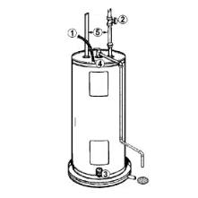
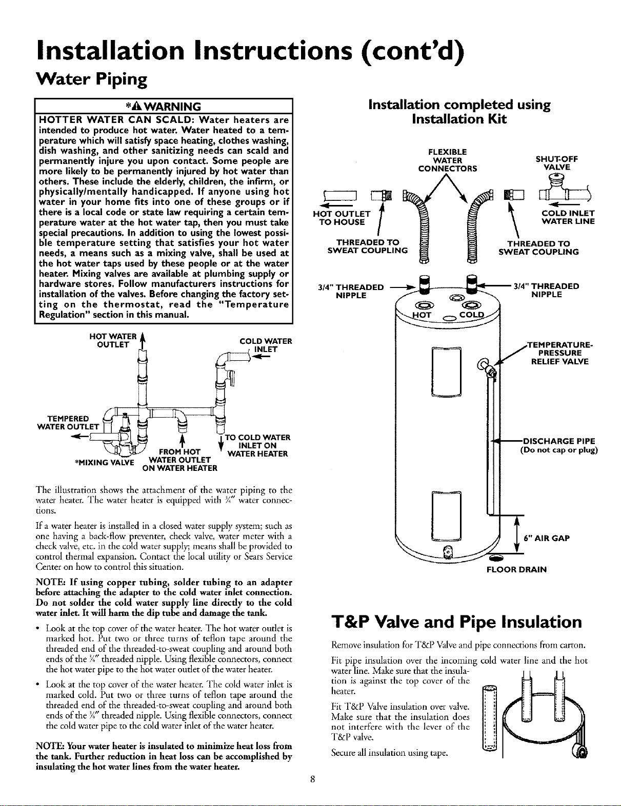
The illustration shows the attachment of the water piping to the
water heater. The water heater is equipped with g" water connec-
tions.
If a water heater is installed in a closed water supply system; such as
one having a back-flow preventer, check valve,water meter with a
check valve,etc. in the coldwater supply;means shallbe provided to
control thermal expansion. Contact the local utility or SearsService
Center on how to control this situation.
NOTE: If using copper tubing, solder tubing to an adapter
before attaching the adapter to the cold water inlet connection.
Do not solder the cold water supply line directly to the cold
water inlet. It wRlharm the dip tube and damage the tank.
•Look at the top coverof the water heater. The hot water outlet is
marked hot. Put two or three turns of teflon tape around the
threaded end of the threaded-to-sweat coupling and around both
ends of the _" dlreaded nipple. Using flexible connectors, connect
the hot water pipe to the hot water outlet of the water heater.
•Look at the top cover of the water heater. The cold water inlet is
marked cold. Put two or three turns of teflon tape around the
threaded end of the threaded-to-sweat coupling and around both
ends of the _" threaded nipple. Using flexible connectors, connect
the coldwater pipe to the cold water inlet of the water heater.
NOTE: Yourwater heater is insulated to minimize heat loss from
the tank. Further reduction in heat loss can be accomplished by
insulating the hot waterlines from the water heater.
Installation completed using
Installation Kit
- t
HOT OUTLET
TO HOUSE
THREADED TO
SWEAT COUPLING
FLEXIBLE
WATER
CONNECTORS SHUT-OFF
VALVE
\--
COLD INLET
WATER LINE
THREADED TO
SWEAT COUPLING
3/4" THREADED __ 3/4" THREADED
NIPPLE _NIPPLE
jTEHPERATURE.
_PRESSURE
_RELIEF VALVE
--DISCHARGE PIPE
(Do not cap or plug)
76" AIR GAP
FLOOR DRAIN
T&P Valve and Pipe Insulation
Remove insulation for T&P Valveand pipe connections from carton.
Fit pipe insulation over the incoming cold water line and the hot
waterline. Make sure thattheinsula-
tion is against the top cover of the
beaten
Fit T&P Valveinsulation over valve.
Make sure that the insulation does
not interfere with the lever of the
T&P valve.
Secureall insulation using tape.
Installation Instructions (cont'd)
Temperature-Pressure
Relief Valve
_,WARNING
At the time of manufacture this water heater was provided
with a combination temperature-pressuras relief valve cer-
tiffed by a nationally recognized testing laboratory that
maintains periodic inspection of production of listed equip-
ment or materials, as meeting the requirements for Relief
Valves and Automatic Gas Shutoff Devices for Hot Water
Supply Systems, and the current edition of ANSI Z21.22 ,
CSA 4.4 and the code requirements of ASHE. If replaced,
the valve must meet the requirements of local codes, but
not less than a combination temperature and pressure
relief valve certified as meeting the requirements for Relief
Valves and Automatic Gas Shutoff Devices for Hot Water
Supply Systems, ANSI Z21.22, CSA 4.4 by a nationally rec-
ognized testing laboratory that maintains periodic inspec-
tion of production of listed equipment or materials.
The valve must be marked with a maximum set pressure
not to exceed the marked hydrostatic working pressure of
the water heater (150 Ibs. p.s.i.) and a discharge capacity
not less than the water heater input rate as shown on the
model rating plate. (Electric heaters -watts divided by 1000
x 3412 equal BTU/Hr. rate.)
Your local jurisdictional authority, while mandating the use
of a temperature-pressure relief valve complying with ANSI
Z21.22, CSA 4.4 and ASME, may require a valve model dif-
ferent from the one furnished with the water heater.
Compliance with such local requirements must be satisfied
by the installer or end user oftbe water heater with a local-
ly prescribed temperature-pressure relief valve installed in
the designated opening in the water heater in place of the
factory furnished valve.
For safe operation of the water heater, the relief valve must
not be removed from it's designated opening or plugged.
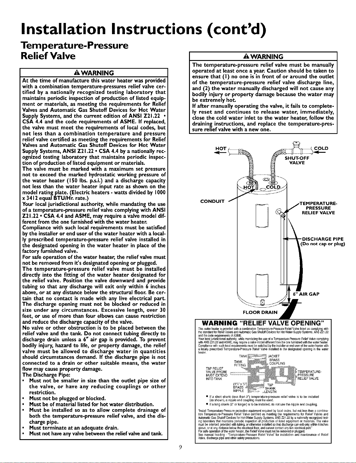
The temperature-pressure relief valve must be installed
directly into the fitting of the water heater designated for
the relief valve. Position the valve downward and provide
tubing so that any discharge will exit only within 6 inches
above, or at any distance below the structural floor. Be cer-
tain that no contact is made with any live electrical part.
The discharge opening must not be blocked or reduced in
size under any circumstances. Excessive length, over 30
feet, or use of more than four elbows can cause restriction
and reduce the discharge capacity of the valve.
No valve or other obstruction is to be placed between the
relief valve and the tank. Do not connect tubing directly to
discharge drain unless a 6" air gap is provided. To prevent
bodily injury, hazard to life, or property damage, the relief
valve must be allowed to discharge water in quantities
should circumstances demand. If the discharge pipe is not
connected to a drain or other suitable means, the water
flow may cause property damage.
The Discharge Pipe:
Must not be smaller in size than the outlet pipe size of
the valve, or have any reducing couplings or other
restriction.
Must not be plugged or blocked.
Must be of material listed for hot water distribution.
Must be installed so as to allow complete drainage of
both the temperature-pressure relief valve, and the dis-
charge pipe.
Must terminate at an adequate drain.
Must not haveany valve between the relief valve and tank.
&WARNING
The temperature-pressure relief valve must be manually
operated at leastoncea year.Caution shouldbe taken to
ensurethat (I) no one isin front of or around the outlet
of the temperature-pressure relief valve dischargeline,
and (2) the water manually dischargedwill not causeany
bodilyinjury or property damagebecausethe water may
be extremely hot.
If after manually operating the valve, it fails to complete-
ly reset and continues to release water, immediately,
closethe cold water inlet to the water heater, follow the
draining instructions,and replace the temperature-pres-
sure relief valvewith a new one.
H_OT( SHUT-OFF
VALVE
COLD
CONDUIT
__ PRESSURE
RELIEF VALVE
(Do not cap or plug)
6" AIR GAP
WARNING "RELIEF VALVE OPENING"
andthe codel_Ji_rnent_ OfASME
Compliance_th suchlocaliequilem_'_tsii_st besa_sf_,dbyth#instaHexol end_selofth_waterheatelw_h
a locally plescribe_JTempelature*Pl_ssureReliefValv_ installedinthe designated_ning in the watel
heater
•If ashort shank (less than 2") temperaltJle.plessurereltef valve isto be installed
(_Sshown), _ nipple andcoupling must be tJsed
•If _ long sha_k/2" or Io_ger) isto be instalEed,do not use the nippEea_d coupling
Aulomat_cGasShutoffDc_4cesfor Hot.WatclSupplySystems,ANSZ2122 bya nationallyrccognizeitcs_*
inglaboratory_hatmant_ns pcdodlcinspec_o_Ofproductionoi listedeq_prn_t or matexialsThe valve
m_s_beodente_J,prov_ed _lh tubing, ol ot_er_se inst_ledsothatdischal_ecmqex_onlyw_hi_6inches
above,Orata_ydis_anc_b_ow thes_ructuralflocl,andcannotcontactany I_veclcctrlcalpar[¸"
Fol safeopclat_onof_hcwa_elbeatel,_hcReliefVa_e m_s_r_t be icmovedorpl_gecd
See mant_alhcadin_- =Temperat_rc*PiessuleRelief Valve"fol installatJonand ma_n_enanc_oi Relief
Va_c, d_SChargc_ipeandothersafe_yprecat_ons
9
Installation Instructions (cont'd)
Filling the Water Heater
"Ib fill the water heater with water:
Close the water heater drain valve by turning the handle to
the right (clockwise). The drain valve is on the lower front of
the water heater.
Open the cold water supply valve to the water heater.
NOTE: The cold water supply valve must be left open
when the water heater is in use.
%insure complete filling of the tank, allow air to exit by
opening the nearest hot water faucet. Allow water to run
until a constant flow is obtained. This will let air out of the
water heater and the piping.
ACAUTION
Never usethis water heater unlessit iscompletely full of
water. To prevent damage to the tank and heating ele-
ment, the tank must be filled with water. Water must
flow from the hot water faucet before turning "ON"
power.
Check all new water piping for leaks. Repair as needed.
Converting the Lower
Element
These instructions only cover the conversion of the convertible
element, read this entire manual before attempting to install or
operate the water heater. The water heater is factory set to oper-
ate at 3800 watts. The lower element can be converted to oper-
ate at 5500 watts. Refer to the "Facts to Consider About the
Location" section.
The Upper Element, (if a double element model) is a conven-
tional 3800 watt element which only operates at its rated
wattage on 240 volts. (See rating plate on water heater).
The Lower Element of the water heater can be converted from
operation at 3800 watts to 5500 watts on a 240 volt system.
If after reading these instructions and this manual, if you do not
understand any portion, call Sears Service Center.
AWARNING
Before making the conversion to 5500 watts, check the
(I) power supply...must be 240 volts, (2) wiring...10 gauge
AWG, Type TW, 60°C or equivalent, and (3) Circuit
breakers or fusing...capable of 30 amp loading. Also, the
installation must conform with this Manual, local codes
and electric utility rules. FAILURE TO COMPLY CAN
RESULT IN DEATH, SERIOUS BODILY INJURY OR
PROPERTY DAMAGE.
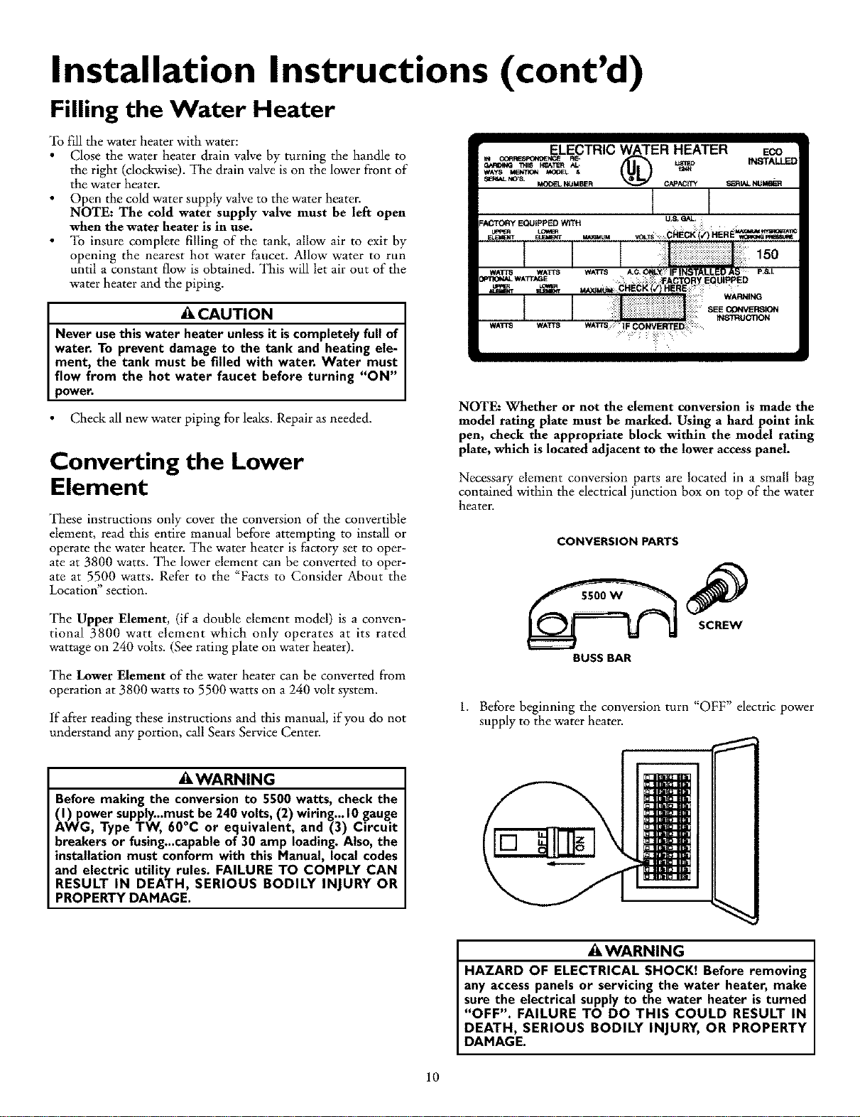
NOTE: Whether or not the element conversion is made the
model rating plate must be marked. Using a hard point ink
pen, check the appropriate block within the model rating
plate, which is located adjacent to the lower access panel.
Necessary element conversion parts are located in a small bag
contained within the electrical junction box on top of the water
heater.
CONVERSION PARTS
BUSS BAR
1. Before beginning the conversion turn "OFF" electric power
supply to the water heater. 1
AWARNING
HAZARD OF ELECTRICAL SHOCK! Before removing
any accesspanels or servicing the water heater, make
sure the electrical supplyto the water heater isturned
"OFF". FAILURE TO DO THIS COULD RESULT IN
DEATH, SERIOUS BODILY INJURY, OR PROPERTY
DAMAGE.
10
Installation Instructions (cont'd)
Converting the Lower
Element (cont'd)
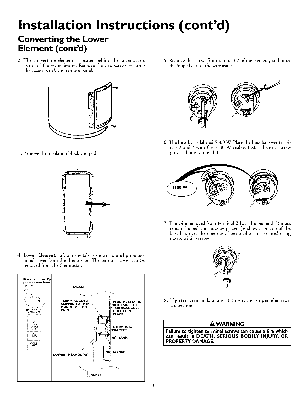
2. The convertible element is located behind the lower access
panel of the water heater. Remove the two screws securing
the access panel, and remove panel.
5. Remove the screws from terminal 2 of the element, and move
the looped end of the wire aside.
3. Remove the insulation block and pad.
6. The buss bar is labeled 5500 W. Place the buss bar overtermi-
nals 2 and 3 with the 5500 W visible. Install the extra screw
provided into terminal 3.
7. The wire removed from terminal 2 has a looped end. It must
remain looped and now be placed (as shown) on top of the
buss bar, over the opening of terminal 2, and secured using
the remaining screw.
4. Lower Element: Lift out the tab as shown to unclip the ter-
minal cover from the thermostat. The terminal cover can be
removed from the thermostat.
Lift out tab to until
term hal cover from
_hermostat, JAeKETli
TERHINALCOVER,
CLIPPED TO THER- \
MOSTAT AT THIS \
POINT \
LOWER THERHOSTAT
PLASTIC TABS ON
BOTH SIDES OF
TERHINAL COVER
HOLD IT iN
PLACE.
THERHOSTAT
/BRACKET
_TANK
ELEHENT
8. Tighten terminals 2 and 3 to ensure proper electrical
connection.
&WARNING
Failure to tighten terminal screws can cause a fire which
can result in DEATH, SERIOUS BODILY INJURY, OR
PROPERTY DAMAGE.
11
Installation Instructions (cont'd)
Converting the Lower
Element (cont'd)
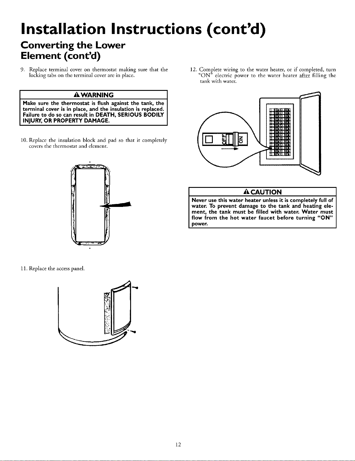
9. Replace terminal cover on thermostat making sure that the
locking tabs on the terminal cover are in place. 12. Complete wiring to the water heater, or if completed, turn
"ON" electric power to the water heater after filling the
tank with water.
_,WARNING
Make sure the thermostat is flush against the tank, the
terminal cover is in place, and the insulation is replaced.
Failure to do so can result in DEATH, SERIOUS BODILY
INJURY, OR PROPERTY DAMAGE.
10. Replace the insulation block and pad so that it completely
covers the thermostat and element.
CAUTION
Never use this water heater unless it is completely full of
water. To prevent damage to the tank and heating ele-
ment, the tank must be filled with water. Water must
flow from the hot water faucet before turning "ON"
power.
11. Replace the access panel.
12
Installation Instructions (cont'd)
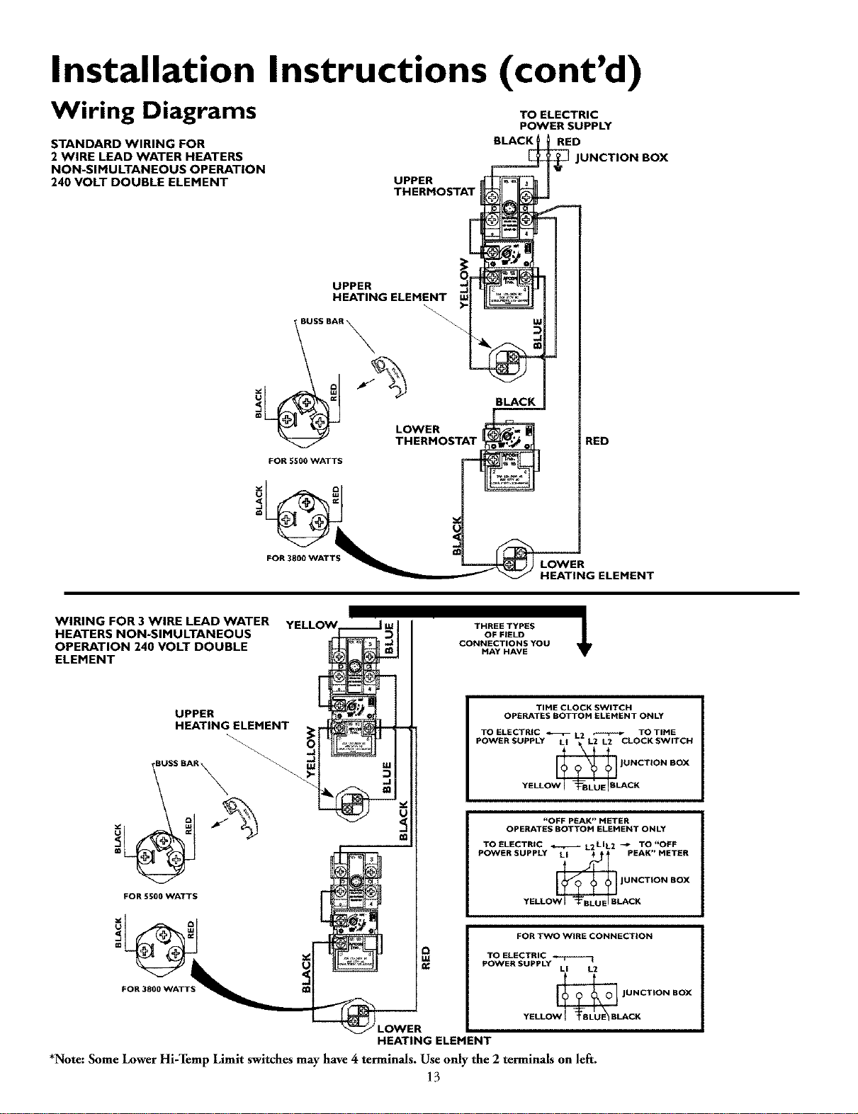
Wiring Diagrams
STANDARD WIRING FOR
2 WIRE LEAD WATER HEATERS
NON-SIMULTANEOUS OPERATION
240 VOLT DOUBLE ELEMENT UPPER
THERMOSTAT
TO ELECTRIC
POWER SUPPLY
RED
UNCTION BOX
UPPER
HEATING ELEMENT
S BAR _
FOR 5500 WATTS
FOR 3800 WATT
BLACK
RED
LOWER
HEATING ELEMENT
WIRING FOR 3 WIRE LEAD WATER
HEATERS NON-SIMULTANEOUS
OPERATION 240 VOLT DOUBLE
ELEMENT
UPPER
HEATING ELEMENT
SS BAR _ _
FOR 5500 WATTS
FOR 3800 WATT_
@
THREETYPES
OFFIELD
CONNECTIONSYOU
MAY HAVE
TIME CLOCK SWITCH
OPERATES BOTTOM ELEMENT ONLY
TO ELECTRIC _L2 _TO TIME
POWERSUPPLY Lt L2 L2 CLOCKSWITCH
YELLO CK
"OFF PEAK _ METER
OPERATES BOTTOM ELEMENT ONLY
TOELECTRtC _L2LIL2 -_ TO"OFF
POWER SUPPLY LI !PEAK _ METER
_ JUNCTION BOX
YELLO LACg
FOR TWO WIRE CONNECTION
TO ELECTRIC
POWER SUPPLY LI L2
Jo_,_l JNCTION BOX
YELL CK
HEATING ELEMENT
*Note: Some LowerHi-Temp Limit switches mayhave 4 terminals, Use only the 2terminals on left.
13
Installation Instructions (cont'd)
Wiring
ACAUTION J
Never usethis water heater unlessit iscompletely full of J
water. To prevent damage to the tank and heating ele- I
ment, the tank must be filled with water. Water must
flowfrom the hot water faucetbefore turn ng on power.
You must provide all wiring of the proper size outside of the
water heater. You must obey local codes and electric company
requirements when you install this wiring.
If you are not familiar with electric codes and practices, or if you
have any doubt, even the slightest doubt, in your ability to con-
nect the wiring to this water heater, obtain the service of a com-
petent electrician. Contact your Sears salesperson to arrange fora
professional electrician.
C. Flexible metal conduit or flexible metallic tubing shall be
permitted for grounding if all the following conditions are
met:
1. The length in any ground return path does not exceed
6 feet.
2. The circuit conductors contained therein are protected
by overcurrent devices rated at 20 amperes or less.
3. The conduit or tubing is terminated in fittings
approved for grounding.
For complete grounding details and all allowable exceptions,
refer to the current edition of the National Electrical Code,
NFPA 70.
4. A standard _" conduit opening has been made in the water
heater junction box for the conduit connection.
AWARNING
WATER HEATERS EQUIPPED FOR ONE VOLTAGE
ONLY: This water heater is equipped for one type volt-
age only.Check the rating plate near the bottom access
panel for the correct voltage. DO NOT use this water
heater with anyvoltageother than the one shownon the
model rating plate. Failureto use the correct voltagecan
cause problems which can result in DEATH, SERIOUS
BODILY INJURY,OR PROPERTY DAMAGE. If you have
anyquestionsor doubts consultyour electric company.
ACAUTION
If wiring from your fuse box or circuit breaker box was
aluminum for your old water heater, replace it with cop-
per wire. If youwishto reusethe existingaluminum wire,
havethe connectionat the water heater made bya com-
petent electrician. Contact your Sears salesperson to
arrange for a professionalelectrician.
5. Wiring Diagrams (See Wiring Diagrams Section) have been
supplied showing the two most common types of connections
between the water heater and the power supply. You can easi-
ly see which type connection you have by removing the junc-
tion box cover on top of the water heater.
A. Two Wire Connection Diagrams: is the most common
requiring you to simply connect red to red, black to
black, and the ground wire to the green ground screw in
the junction box of the water heater.
B, Three Wire Connection Diagram: is used when you are
connecting the water heater to power a supply that has a
"Time Clock" or "Off Peak" Meter. _lb make these con-
nections refer to block 1 or 2 in this wiring diagram for
the type of system you have.
NOTE: If you have purchased a three wire connection
water heater but you are not on a "Time Clock" or "Off
Peak" meter and have a standard two wire connection
power supply, simply follow the connection diagram in
block 3. of the Three Wire Connection Diagram.
1. Provide a way to easily shut off" the electric power when
working on the water heater. This could be with a circuit
breaker or fuse block in the entrance box or a separate dis-
connect switch.
2. Install and connect a circuit directly from the main fuse or
circuit breaker box. This circuit must be the right size and
have its own fuse or circuit breaker. Refer to the chart in the
"Product Specifications" section for the correct size wire and
fuse circuit breaker.
6.
7.
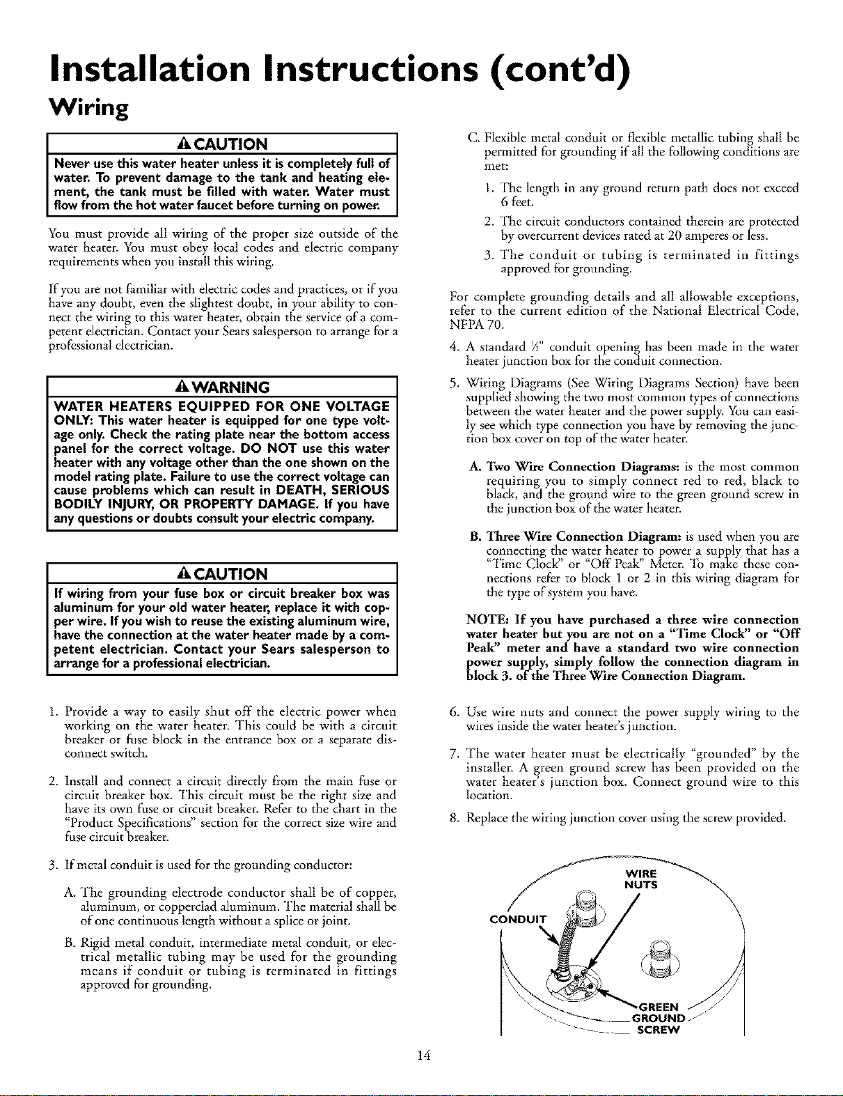
Use wire nuts and connect the power supply wiring to the
wires inside the water heater's junction.
The water heater must be electrically "grounded" by the
installer. A green ground screw has been provided on the
water heater's junction box. Connect ground wire to this
location.
8. Replace the wiring junction cover using the screw provided.
3. If metal conduit is used for the grounding conductor:
A. The grounding electrode conductor shall be of copper,
aluminum, or copperclad aluminum. The material shall be
of one continuous length without a splice or joint.
B. Rigid metal conduit, intermediate metal conduit, or elec-
trical metallic tubing may be used for the grounding
means if conduit or tubing is terminated in fittings
approved for grounding.
CONDUIT
WIRE
NUTS
-GREEN
GROUND
SCREW
14
Installation Instructions (cont'd)
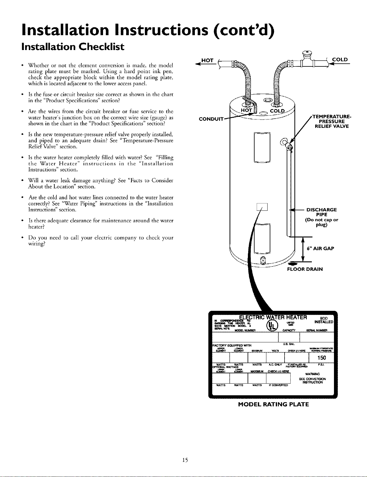
Installation Checklist
•Whether or not the element conversion is made, the model
rating plate must be marked• Using a hard point ink pen,
check the appropriate block within the model rating plate,
which is located adjacent to the lower accesspanel.
•Is the fuse or circuit breaker size correct as shown in the chart
in the "Product Specifications" section?
•Are the wires from the circuit breaker or fuse service to the
water heater's junction box on the correct wire size (gauge) as
shown in the chart in the "Product Specifications" section?
• ls the new temperature-pressure relief valve properly installed,
and piped to an adequate drain? See "'i_mperature-Pressure
Relief Valve" section•
• ls the water heater completely filled with water? See "Filling
the Water Heater" instructions in the "Installation
Instructions section.
• Will a water leak damage anything? See "Facts to Consider
About the Location" section•
•Are the cold and hot water lines connected to the water heater
correctly? See "Water Piping" instructions in the "Installation
lnstrucnons section.
•Is there adequate clearance for maintenance around the water
heater?
•Do you need to call your electric company to check your
wiring?
COLD
TEMPERATURE.
PRESSURE
RELIEF VALVE
:HARGE
PIPE
(Do not cap or
plug)
L
6" AIR GAP
FLOOR DRAIN
MODEL RATING PLATE
15
Service and Adjustment
Temperature Regulation
&WARNING
HOTTER WATER CAN SCALD: Water heaters are
intended to produce hot water. Water heated to a tem-
perature which will satisfy space heating, clothes wash-
ing, dish washing, and other sanitizing needs can scald
and permanently injure you upon contact. Some people
are more likely to be permanently injured by hot water
than others. These include the elderly, children, the
infirm, or physically/mentally handicapped. If anyone
using hot water in your home fits into one of these
groups or if there is a local code or state law requiring a
certain temperature water at the hot water tap, then
you must take special precautions. In addition to using
the lowest possible temperature setting that satisfies
_'our hot water needs, a means such as a mixing valve,
shall be used at the hot water taps used by these people
or at the water heater. Mixing valves are available at
plumbing supply or hardware stores. Follow manufactur-
ers instructions for installation of the valves. Before
changing the factory setting on the thermostat, read the
"Temperature Regulation" section in this manual.
&WARNING
Never allow small children to useahot water tap, or to
draw their own bath water. Never leaveachild or handi-
cappedpersonunattended in a bathtub or shower.
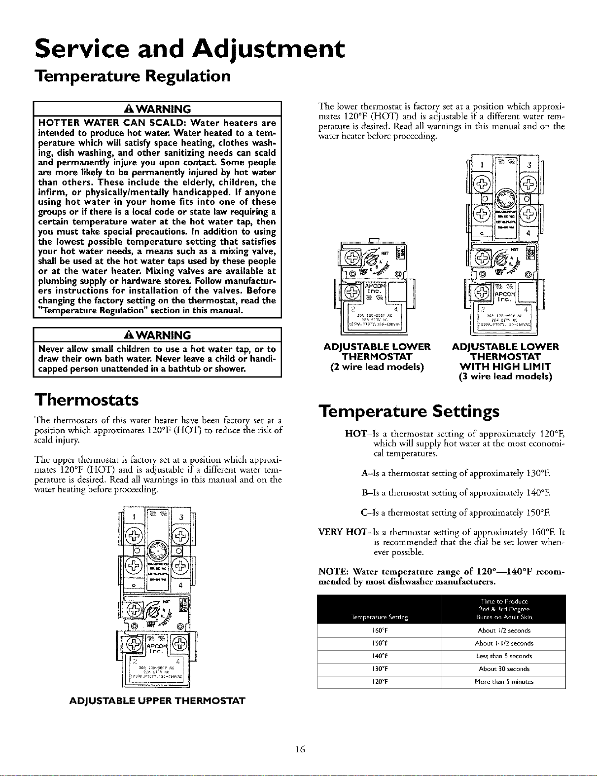
The lower thermostat is factory set at a position which approxi-
mates 120°F (HO13 and is adjustable if a different water tem-
perature is desired. Read all warnings in this manual and on the
water heater before proceeding.
Z
@
4
ADJUSTABLE LOWER
THERMOSTAT
(2 wire lead models)
ADJUSTABLE LOWER
THERMOSTAT
WITH HIGH LIMIT
(3 wire lead models)
Thermostats
The thermostats of this water heater have been factory set at a
position which approximates 120°F (HOT) to reduce the risk of
scald injury.
The upper thermostat is factory set at a position which approxi-
mates 120°F (HOT) and is adjustable if a dilrlerent water tem-
perature is desired. Read all warnings in this manual and on the
water heating before proceeding.
_ 4
©
Temperature Settings
HOT-Is a thermostat setting of approximately 120°F,
which will supply hot water at the most economi-
cal temperatures.
A-Is a thermostat setting of approximately 130°E
B-Is a thermostat setting of approximately 140°E
C-Is a thermostat setting of approximately 150°E
VERY HOT-Is a thermostat setting of approximately 160°E It
is recommended that the dial be set lower when-
ever possible.
NOTE: Water temperature range of 120°--140°F recom-
mended by most dishwasher manufacturers.
t60°F ABout 1/2 seconds
150°F ABout I -1/2 seconds
140°F Lessthan 5 seconds
130°F About 30 seconds
120°F Hore than 5 minutes
ADJUSTABLE UPPER THERMOSTAT
16
Service Adjustment (cont'd)
Upper and Lower Thermostat
Adjustment
(Refer to thermostat illustrations under
"Thermostats")
NOTE: It is not necessary to adjust the upper thermostat.
However, if it is adjusted above the factory set point of
120°F (HOT) is is recommended that it not be set higher
than the lower thermostat setting.
The upper and lower thermostats are adjustable if a different
water temperature is desired. Read all warnings in the
"_l_mperature-Regulation" section before proceeding.
1. _lhrn "OFF" the electrical power to the water heater at the
junction box.
2. Take of/" the upper and/or lower access panel, insulation
block and pad.
3. The slotted a_stment (using a screwdriver) can be turned
clockwise (f "_) to increase the temperature settin_ or
counter clockwise (_) to decrease the temperature
setting.
4. Replace the insulation block, pad and accesspanel.
5. _lhrn "ON" the power supply.
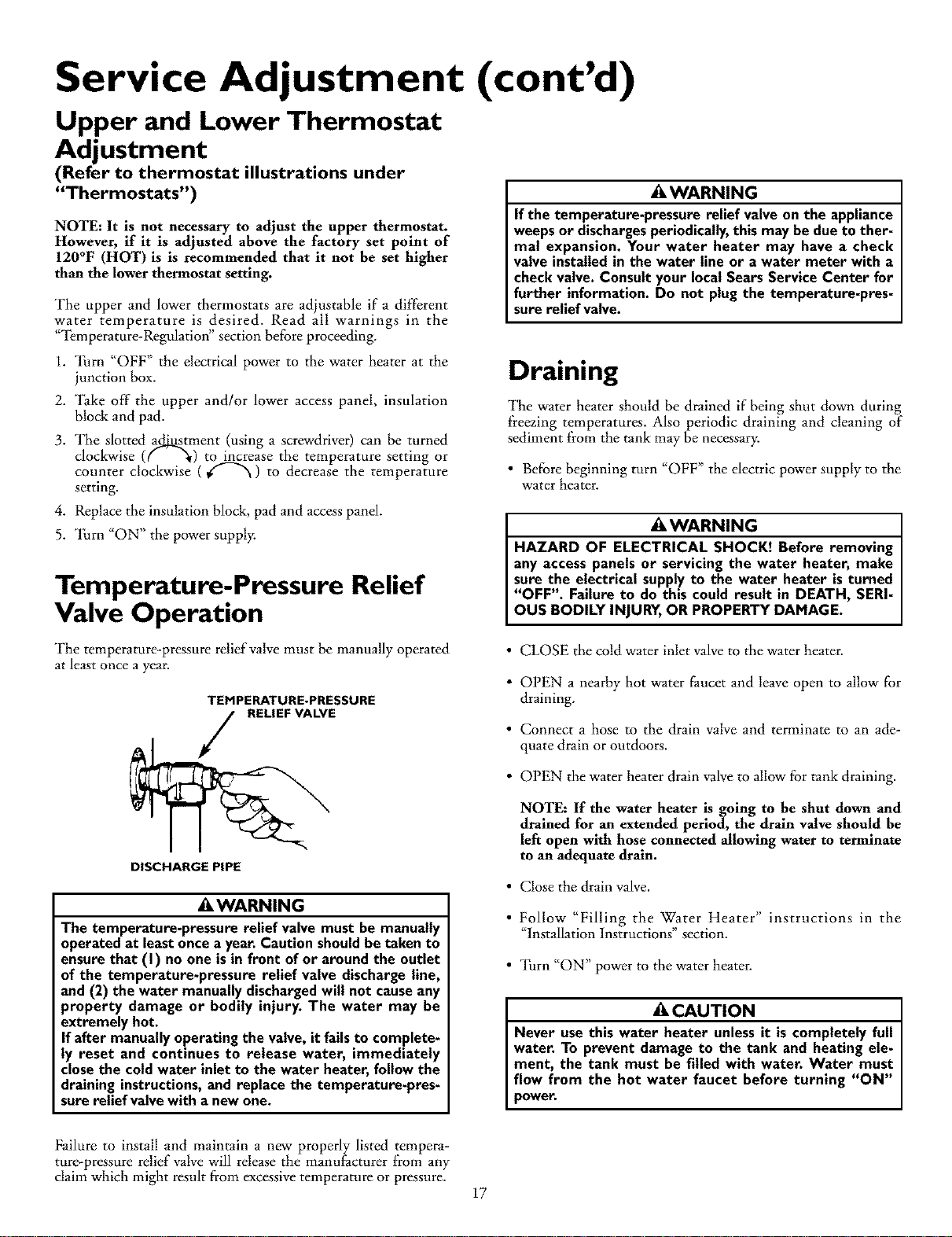
Temperature-Pressure Relief
Valve Operation
AWARNING
If the temperature-pressure relief valveon the appliance
weepsor dischargesperiodically,this may bedue to ther-
mal expansion. Your water heater may have a check
valve installedin the water line or a water meter with a
checkvalve. Consultyour localSears Service Center for
further information. Do not plugthe temperature-pres-
sure relief valve.
Draining
The water heater should be drained if being shut down during
freezing temperatures. Also periodic draining and cleaning of
sediment from the tank may be necessary.
• Before beginning turn "OFF" the electric power supply to the
water heater.
AWARNING
HAZARD OF ELECTRICAL SHOCK! Before removing
any accesspanels or servicing the water heater, make
sure the electrical supplyto the water heater isturned
"OFF". Failure to do this could result in DEATH, SERI-
OUS BODILY INJURY,OR PROPERTY DAMAGE.
The temperature-pressure relief valve must be manually operated
at least once a year.
TEMPERATURE.PRESSURE
RELIEF VALVE
DISCHARGE PIPE
AWARNING
The temperature-pressure relief valve must be manually
operated at leastoncea year.Caution shouldbe taken to
ensurethat (I) no one isin front of or around the outlet
of the temperature-pressure relief valve dischargeline,
and (2) the water manually dischargedwill not causeany
property damage or bodily injury. The water may be
extremely hot.
If after manually operating the valve, it fails to complete-
ly reset and continues to release water, immediately
closethe cold water inlet to the water heater, follow the
draining instructions,and replace the temperature-pres-
sure relief valvewith a new one.
• CLOSE the cold water inlet valveto the water heater.
• OPEN a nearby hot water faucet and leave open to allow for
draining.
• Connect a hose to the drain valve and terminate to an ade-
quate drain or outdoors.
• OPEN the water heater drain valveto allow for tank draining.
NOTE: If the water heater is going to be shut down and
drained for an extended period, the drain valve should be
left open with hose connected allowing water to terminate
to an adequate drain.
• Close the drain valve.
• Follow "Filling the Water Heater" instructions in the
"Installation Instructions" section.
• Turn "ON" power to the water heater.
ACAUTION
Never use this water heater unless it is completely full
water. To prevent damage to the tank and heating ele-
ment, the tank must be filled with water. Water must
flow from the hot water faucet before turning "ON"
power.
Failure to install and maintain a new properly listed tempera-
ture-pressure relief valve will release the manufacturer from any
claim which might result from excessive temperature or pressure. 17
Service and Adjustment (cont'd)
Element Cleaning/
Replacement
NOTE: These instructions are written for element cleaning
and element replacement for the lower element. If it is neces-
sary to clean or replace the upper element, then repeat these
instructions.
"Ib remove the element from your tank in order to clean or
replace it:
1. Before beginning turn "OFF" the electric power supply to the
water heater.
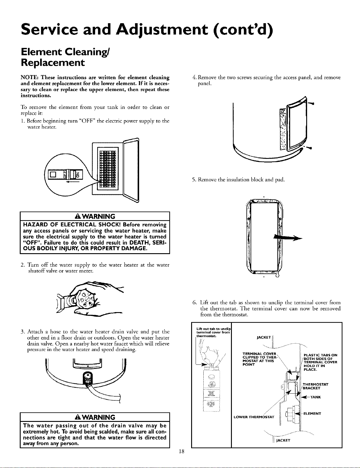
4. Remove the two screws securing the access panel, and remove
panel.
]5. Remove the insulation block and pad.
AWARNING
HAZARD OF ELECTRICAL SHOCK! Before removing
any accesspanels or servicing the water heater, make
sure the electrical supplyto the water heater isturned
"OFF". Failure to do this could result in DEATH, SERI-
OUS BODILY INJURY,OR PROPERTY DAMAGE.
2. Turn off the water supply to the water heater at the water
shutoff'valve or water meter.
6. Lift out the tab as shown to unclip the terminal cover from
the thermostat. The terminal cover can now be removed
ftom the thermostat.
3. Attach a hose to the water heater drain valve and put the
other end in a floor drain or outdoors. Open the water heater
drain valve. Open a nearby hot water faucet which will relieve
pressure in the water heater and speed draining.
AWARNING
The water passing out of the drain valve may be
extremely hot. To avoidbeingscalded,make sure all con-
nections are tight and that the water flow is directed
awayfrom anyperson. 18
Lift out tab to until
term hal cover from
_hermostat, JACKETli
TERHINALCOVER,
CLIPPED TO THER- \
MOSTAT AT THIS \
POINT \\
LOWER THERHOSTAT
PLASTIC TABS ON
/BOTH SIDES OF
TERMINAL COVER
HOLD IT IN
pLACE.
THERHOSTAT
/BRACKET
_TANK
ELEHENT
Service and Adjustment (cont'd)
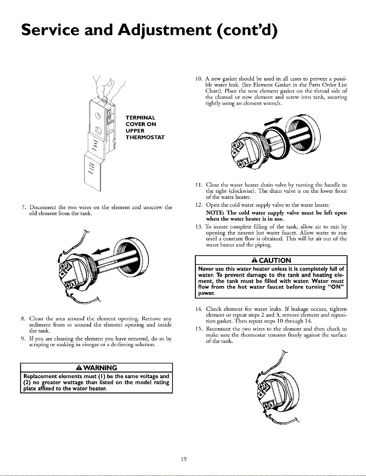
TERMINAL
COVER ON
UPPER
THERMOSTAT
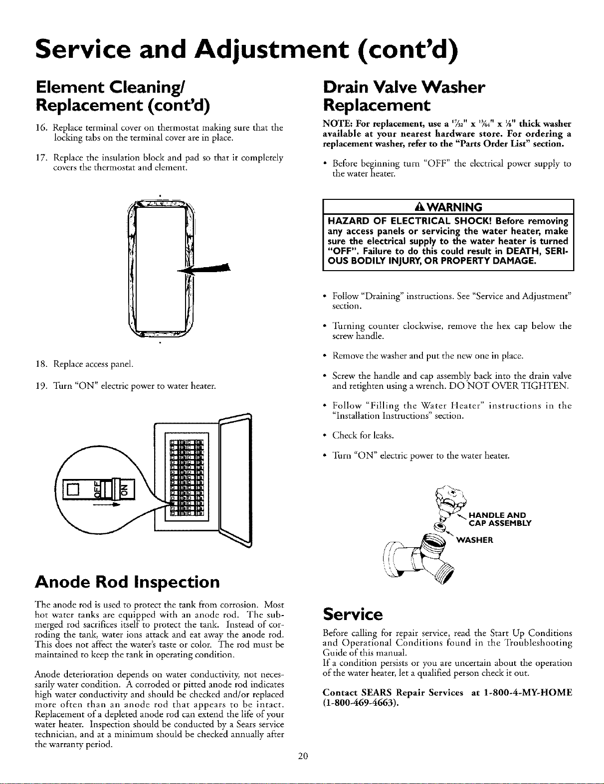
10. A new gasket should be used in all cases to prevent a possi-
ble water leak. (See Element Gasket in the Parts Order List
Chart). Place the new element gasket on the thread side of
the cleaned or new element and screw into tank, securing
tightly using an element wrench.
7. Disconnect the two wires on the element and unscrew the
old element from the tank.
8. Clean the area around the element opening. Remove any
sediment from or around the element opening and inside
the tank.
9. If you are cleaning the element you have removed, do so by
scraping or soaking in vinegar or a de-liming solution.
AWARNING
Replacementelements must (I) bethe same voltage and
(2) no greater wattage than listed on the model rating
plate affixedto the water heater.
11. Close the water heater drain valve by turning the handle to
the right (clockwise). The drain valve is on the lower front
of the water heater.
12. Open the cold water supply valveto the water heater.
NOTE: The cold water supply valve must be left open
when the water heater is in use.
13. _b insure complete filling of the tank, allow air to exit by
opening the nearest hot water faucet. Allow water to run
until a constant flow is obtained. This will let air out of the
water heater and the piping.
ACAUTION
Never usethis water heater unless it iscompletely full of
water. To prevent damage to the tank and heating ele-
ment, the tank must be filled with water. Water must
flow from the hot water faucet before turning "ON"
power.
14. Check element for water leaks. If leakage occurs, tighten
element or repeat steps 2 and 3, remove element and reposi-
tion gasket. Then repeat steps 10 through 14.
15. Reconnect the two wires to the element and then check to
make sure the thermostat remains firmly against the surface
of the tank.
19
Service and Adjustment (cont'd)
Element Cleaning/
Replacement (cont'd)
16. Replace terminal cover on thermostat making sure that the
locking tabs on the terminal cover are in place.
17. Replace the insulation block and pad so that it completely
covers the thermostat and element.
Drain Valve Washer
Replacement
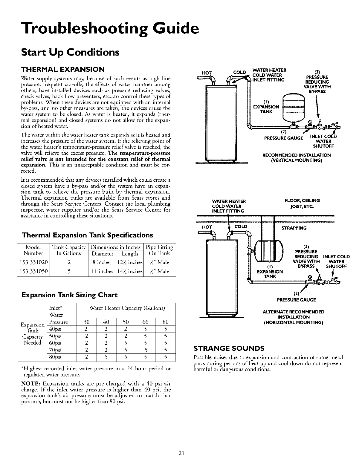
NOTE: For replacement, use a _2" x _¾_"x _" thick washer
available at your nearest hardware store. For ordering a
replacement washer, refer to the "Parts Order List" section.
•Before beginning turn "OFF" the electrical power supply to
the water heater.
AWARNING
HAZARD OF ELECTRICAL SHOCK! Before removing
any accesspanels or servicing the water heater, make
sure the electrical supplyto the water heater isturned
"OFF". Failure to do this could result in DEATH, SERI-
OUS BODILY INJURY,OR PROPERTYDAMAGE.
18. Replace access panel.
19. Turn "ON" electric power to water heater.
•Follow "Draining" instructions. See "Service and Adjustment"
section.
• Turning counter clockwise, remove the hex cap below the
screw handle.
• Remove the washer and put the new one in place.
• Screw the handle and cap a_ssemblyback into the drain valve
and retighten using a wrench. DO NOT OVER TIGHTEN.
•Follow "Filling the Water Heater" instructions in the
"Installation Instructions" section.
• Check for leaks.
• _lhrn "ON" electric power to the water heater.
Anode Rod Inspection
The anode rod is used to protect the tank from corrosion. Most
hot water tanks are equipped with an anode rod. The sub-
merged rod sacrifices itself to protect the tank. Instead of cor-
roding the tank, water ions attack and eat away the anode rod.
This does not aftect the water's taste or color. The rod must be
maintained to keep the tank in operating condition.
Anode deterioration depends on water conductivity, not neces-
sarily water condition. A corroded or pitted anode rod indicates
high water conductivity and should be checked and/or replaced
more often than an anode rod that appears to be intact.
Replacement of a depleted anode rod can extend the life of your
water heater. Inspection should be conducted by a Sears service
technician, and at a minimum should be checked annually after
the warranty period.
Service
Before calling for repair service, read the Start Up Conditions
and Operational Conditions found in the Troubleshooting
Guide of this manual.
If a condition persists or you are uncertain about the operation
of the water heater, let a qualified person check it out.
Contact SEARS Repair Services at 1-800-4-MY-HOME
(1-800-469-4663).
20
Troubleshooting Guide
Start Up Conditions
THERMAL EXPANSION
Water supply systems may, because of such events as high line
pressure, frequent cut-off_, the effects of water hammer among
others, have installed devices such as pressure reducing valves,
check valves, back flow preventers, etc.-to control these types of
_roblems. When these devices are not equipped with an internal
y-pass, and no other measures are taken, the devices cause the
water system to be dosed. As water is heated, it expands (ther-
mal expansion) and closed systems do not allow for the expan-
sion of heated water.
The water within the water heater tank expands as it is heated and
increases the pressure of the water system. If the relieving point of
the water heater's temperature-pressure relief valve is reached, the
valve will relieve the excess pressure. The temperature-pressure
relief valve is not intended for the constant relief of thermal
expansion. This is an unacceptable condition and must be cor-
rected.
It is recommended that any devices installed which could create a
closed system have a by-pass and/or the system have an expan-
sion tank to relieve the pressure built by thermal expansion.
Thermal expansion tanks are available from Sears stores and
through the Sears Service Centers. Contact the local plumbing
inspector, water supplier and/or the Sears Service Center for
assistance in controlling these situations.
Thermal Expansion Tank Specifications
Model _lhnkCapacity Dimensions in Inches Pipe Fitting
Number In Gallons Diameter Length On "Ihnk
153.331020 2 8 inches 12_ inches 74"Male
153.331050 5 11 inches 14_ inches 74"Male
Expansion Tank Sizing Chart
Expansion
_nk
Capacity
Needed
Inlet*
Water
Pressure
40psi
50psi
60psi
70psi
80psi
Water Heater Capacity (Gallons)
30 40 50 66 80
22255
2 2 2 5 5
2 2 5 5 5
2 2 5 5 5
25555
*Highest recorded inlet water pressure in a 24 hour period or
regulated water pressure.
NOTE: Expansion tanks are pre-charged with a 40 psi air
charge.. If the inlet,. water pressure is higJ.her than 40 psi, the
expansmn tanks a_r pressure must be adjusted to match that
pressure, but must not he higher than 80 psi.
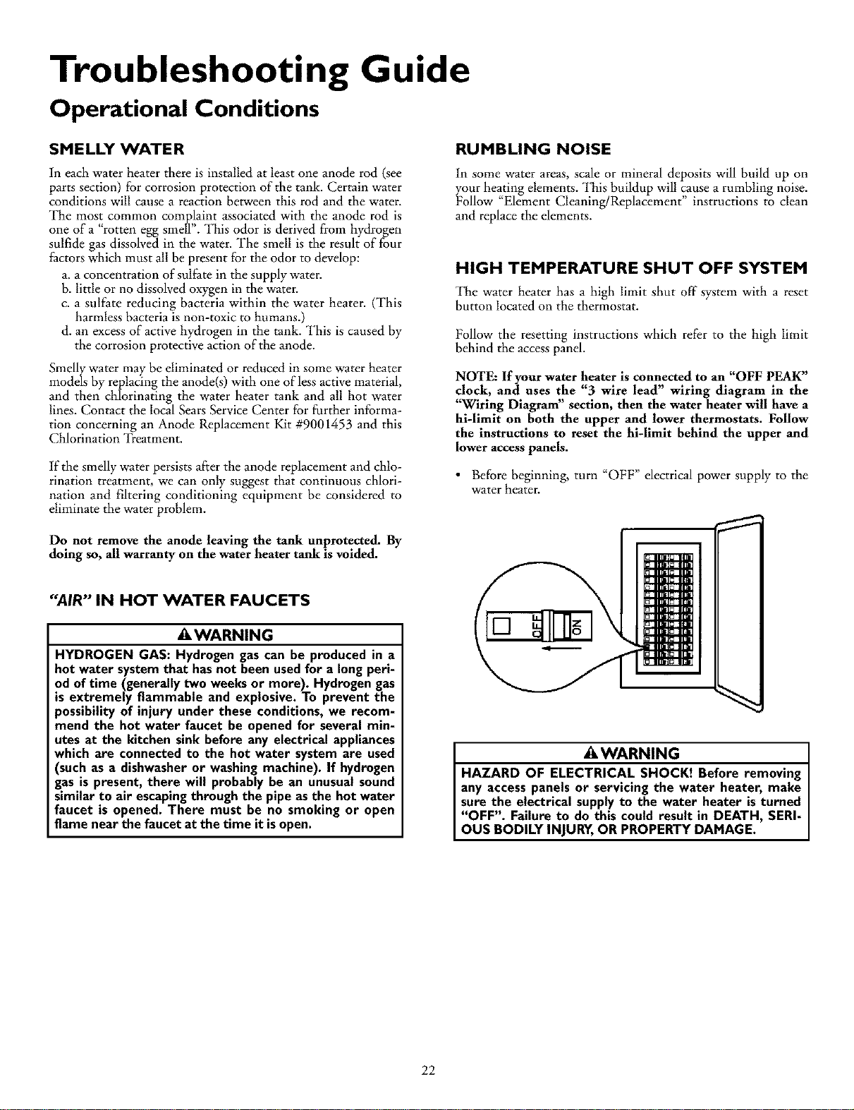
HOT COU_ WATER HEATER (3)
-COLD WATER PRESSURE
INLET FITTING REDUCING
VALVEWITH
BY-PASS
(0 1
EXPANSION
TANK
(z)
PRESSUREGAUGE WATER
SHUTOFF
RECOMMENDED INSTALLATION
(VERTICAL MOUNTING)
WATER HEATER
COLD WATER
INLET FITTING
FLOOR, CEILING
JOIST,ETC.
HOT COLD STRAPPING
O)
EXPANSION
TANK
(3)
PRESSURE
REDUCING INLETCOLD
VALVEWITH WATER
BY-PASS SHUTOFF
(z)_
PRESSUREGAUGE
ALTERNATE RECOMMENDED
INSTALLATION
(HORIZONTAL MOUNTING)
STRANGE SOUNDS
Possible noises due to expansion and contraction of some metal
_arts during periods of heat-up and cool-down do not represent
armful or dangerous conditions.
21
Troubleshooting Guide
Operational Conditions
SMELLY WATER
In each water heater there is installed at least one anode rod (see
parts section) for corrosion protection of the tank. Certain water
conditions will cause a reaction between this rod and the water.
The most common complaint associated with the anode rod is
one of a "rotten egg smell". This odor is derived from hydrogen
sulfide gas dissolved in the water. The smell is the result of four
factors which must all be present for the odor to develop:
a. a concentration of sulfate in the supply water.
b. little or no dissolved oxygen in the water.
c. a sulfate reducing bacteria within the water heater. (This
harmless bacteria is non-toxic to humans.)
d. an excess of active hydrogen in the tank. This is caused by
the corrosion protective action of the anode.
Smelly water may be eliminated or reduced in some water heater
models by replacing the anode(s) with one of less active material,
and then chlorinating the water heater tank and all hot water
lines. Contact the local Sears Service Center for further informa-
tion concerning an Anode Replacement Kit #9001453 and this
Chlorination Treatment.
If the smelly water persists after the anode replacement and chlo-
rination treatment, we can only suggest that continuous chlori-
nation and filtering conditioning equipment be considered to
eliminate the waterproblem.
RUMBLING NOISE
In some water areas, scale or mineral deposits will build up on
your heating elements. This buildup will cause a rumbling noise.
Follow "Element Cleaning/Replacement" instructions to clean
and replace the elements.
HIGH TEMPERATURE SHUT OFF SYSTEM
The water heater has a high limit shut off"system with a reset
button located on the thermostat.
Follow the resetting instructions which refer to the high limit
behind the access panel.
NOTE: If your water heater is connected to an "OFF PEAK"
clock, and uses the "3 wire lead" wiring diagram in the
"W'tring Diagram" section, then the water heater will have a
hi-limit on both the upper and lower thermostats. Follow
the instructions to reset the hi-limit behind the upper and
lower access panels.
• Before beginning, turn "OFF" electrical power supply to the
water heater.
Do not remove the anode leaving the tank unprotected. By
doing so, all warranty on the water heater tank is voided.
"AIR" IN HOT WATER FAUCETS
AWARNING
HYDROGEN GAS: Hydrogen gas can be produced in a
hot water system that has not been used for a long peri-
od of time (generallytwo weeksor more). Hydrogen gas
is extremely flammable and explosive. To prevent the
possibility of injury under these conditions, we recom-
mend the hot water faucet be opened for several min-
utes at the kitchen sink before any electrical appliances
which are connected to the hot water system are used
(such as a dishwasheror washing machine). If hydrogen
gas is present, there will probably be an unusual sound
similar to air escapingthrough the pipe as the hot water
faucet is opened. There must be no smoking or open
flame near the faucet at the time it isopen.
AWARNING
HAZARD OF ELECTRICAL SHOCK! Before removing
any accesspanels or servicing the water heater, make
sure the electrical supplyto the water heater isturned
"OFF". Failure to do this could result in DEATH, SERI-
OUS BODILY INJURY,OR PROPERTY DAMAGE.
22
Troubleshooting Guide (cont'd)
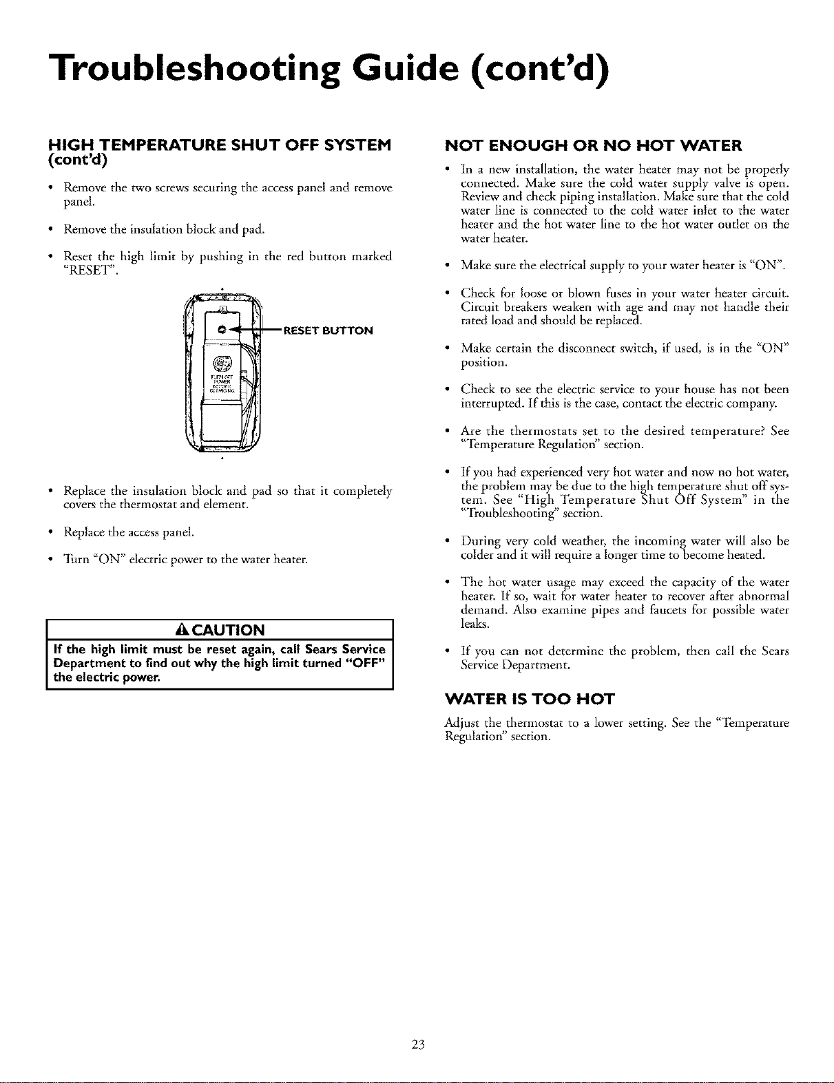
HIGH TEMPERATURE SHUT OFF SYSTEM
(cont'd)
•Remove the two screws securingthe access panel and remove
panel.
• Remove the insulation block and pad.
• Reset the high limit by pushing in the red button marked
"RESET".
O_ _I RESET BUTTON
@
ru_nc.rr
• Replace the insulation block and pad so that it completely
covers the thermostat and element.
• Replace the access panel.
• "lhrn "ON" electric power to the water heater.
ACAUTION
If the high limit must be reset again, call Sears Service
Department to find out why the high limit turned "OFF"
the electric power.
NOT ENOUGH OR NO HOT WATER
In a new installation, the water heater may not be properly
connected. Make sure the cold water supply valve is open.
Review and check piping installation. Make sure that the cold
water line is connected to the cold water inlet to the water
heater and the hot water line to the hot water outlet on the
water heater.
• Make sure the electrical supply to your water heater is "ON".
• Check for loose or blown fuses in your water heater circuit.
Circuit breakers weaken with age and may not handle their
rated load and should be replaced.
• Make certain the disconnect switch, if used, is in the "ON"
position.
• Check to see the electric service to your house has not been
interrupted, lfthis is the case, contact the electric company.
• Are the thermostats set to the desired temperature? See
"'_(_mperature Regulation" section.
• If you had experienced very hot water and now no hot water,
the problem may be due to the high temperature shut off'sys-
tem. See "High Temperature Shut Off" System" in the
"Troubleshooting" section.
• During very cold weather, the incoming water will also be
colder and it will require a longer time to become heated.
• The hot water usage may exceed the capacity of the water
heater. If so, wait for water heater to recover after abnormal
demand. Also examine pipes and faucets for possible water
leaks.
• If you can not determine the problem, then call the Sears
Service Department.
WATER IS TOO HOT
Adjust the thermostat to a lower setting. See the "_(_mperature
Regulation" section.
23
Troubleshooting Guide (cont'd)
Leakage Checkpoints
Use this guide to check a "Leaking" water heater. Many suspect-
ed "Leakers" are not leaking tanks. Often the source of the water
can be found and corrected.
If you are not thoroughly familiar with electric codes, the water
heater, and safety practices, contact your local Sears Service
Center to check the water heater.
ACAUTION
Read this manual first, then before checkingthe water
heater make sure the electric supply has been turned
"OFF", and never turn the electric supply"ON" before
the tank iscompletely full ofwater.
®
®
©
©
®
®
@
@
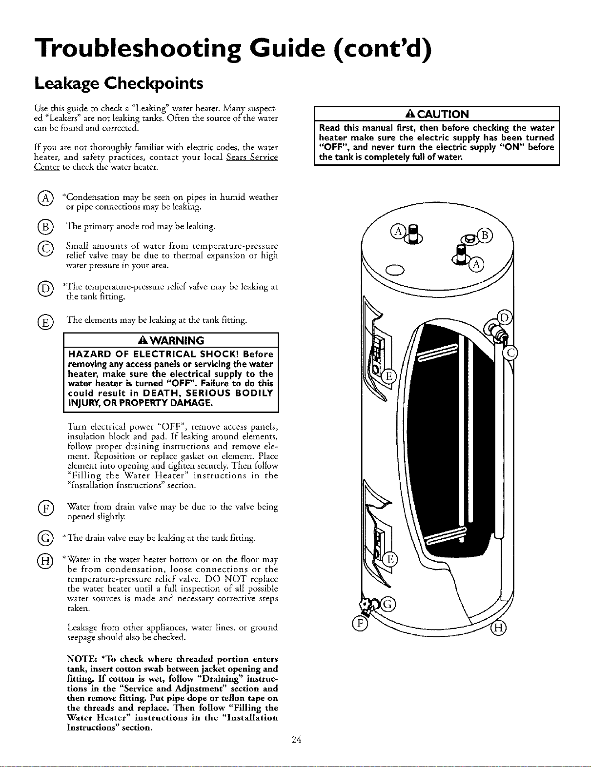
*Condensation may be seen on pipes in humid weather
or pipe connections may be leaking.
The primary anode rod may be leaking.
Small amounts of water from temperature-pressure
relief valve may be due to thermal expansion or high
water pressure m your area.
*The temperature-pressure relief valve may be leaking at
the tank fitting.
The elements may be leaking at the tank fitting.
AWARNING
HAZARD OF ELECTRICAL SHOCK! Before
removing anyaccesspanelsor servicingthe water
heater, make sure the electrical supply to the
water heater isturned "OFF". Failure to do this
could result in DEATH, SERIOUS BODILY
INJURY,OR PROPERTY DAMAGE.
Turn electrical power "OFF", remove access panels,
insulation block and pad. If leaking around elements,
follow proper draining instructions and remove ele-
ment. Reposition or replace gasket on element. Place
element into opening and tighten securely. Then follow
"Filling the Water Heater" instructions in the
"Installation Instructions" section.
Water from drain valve may be due to the valve being
opened slightly.
*The drain valve may be leaking at the tank fitting.
*Water in the water heater bottom or on the floor may
be from condensation, loose connections or the
temperature-pressure relief valve. DO NOT replace
the water heater until a full inspection of all possible
water sources is made and necessary corrective steps
taken.
Leakage ftom other appliances, water lines, or ground
seepage should also be checked.
NOTE: *To check where threaded portion enters
tank, insert cotton swab between jacket opening and
fitting. If cotton is wet, follow "Draining" instruc-
tions in the "Service and Adjustment" section and
then remove fitting. Put pipe dope or teflon tape on
the threads and replace. Then follow "Filling the
Water Heater" instructions in the "Installation
Instructions" section. 24
O

Notes
25
Parts Order List
KENMORE POWER MISER rM6 ELECTRIC WATER HEATERS
MODEL NUMBERS:
153.326360 30 Gal.
153.326361 30 Gal.
153.326460 40 Gal.
153.326461 40 Gal.
153.326560 50 Gal.
153.326561 50 Gal.
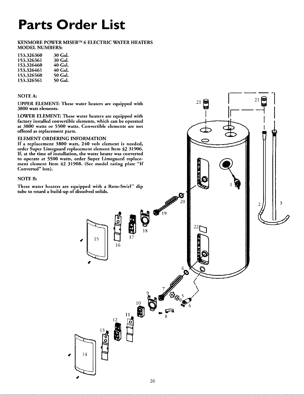
NOTE A:
UPPER ELEMENT: These water heaters are equipped with
3800 watt elements.
LOWER ELEMENT: These water heaters are equipped with
factory installed convertible elements, which can be operated
at 3800 watts or 5500 watts. Convertible elements are not
offered as replacement parts.
ELEMENT ORDERING INFORMATION
If a replacement 3800 watt, 240 volt element is needed,
order Super Limeguard replacement element Item 42 31906.
If, at the time of installation, the water heater was converted
to operate at 5500 watts, order Super Limeguard replace-
ment element Item 42 31908. (See model rating plate "If
Converted" box).
NOTE B:
These water heaters are equipped with aRoto-SwirF _dip
tube to retard a build-up of dissolved solids.
6
10
26
Parts Order List (cont'd)
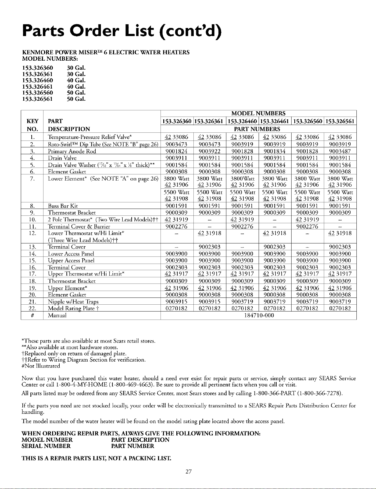
KENMORE POWER MISERTM 6ELECTRIC WATER HEATERS
MODEL NUMBERS:
153.326360 30GM.
153.326361 30GM.
153.326460 40GM.
153.326461 40GM.
153.326560 50GM.
153.326561 50GM.
KEY PART
NO. DESCRIPTION
1. _l_mperature-Pressure Relief Valve*
2. Roto-SwirlTM Dip "lhbe(SeeNOTE "B" page 26)
3. Primary Anode Rod
4. Drain Valve
5. Drain ValveWasher (_7_2"x13/6_/'x _" thick)**
6. Element Gasket
7. Lower Element* (See NOTE "A"on page 26)
153.326360 153.326361 153.326560 153.326561
4233086
9003473
9001824
9003911
9001584
9000308
3800Watt
4231906
5500Watt
4231908
9001591
9000309
4231919
9002276
42 33086
9003473
9003922
9003911
9001584
9000308
3800Watt
42 31906
5500Watt
42 31908
9001591
9000309
4233086
9003919
9001828
9003911
9001584
9000308
3800Watt
42319O6
5500Watt
4231908
9001591
9000309
4231919
9002276
MODEL NUMBERS
153.326460 153.326461
PART NUMBERS
42 33086 42 33086
9003919 9003919
9001828 9001834
9003911 9003911
9001584 9001584
9000308 9000308
3800Watt 3800Watt
42 31906 42 31906
5500Watt 5500Watt
42 31908 42 31908
9001591 9001591
9000309 9000309
42 31919 -
9002276 -
-42 31918
- 9002303
9003900 9003900
9003900 9003900
9002303 9002303
42 31917 42 31917
9000309 9000309
42 31906 42 31906
9000308 9000308
9003719 9003719
0270182 0270182
184710-000
8. Buss Bar Kit
9. Thermostat Bracket
10. 2 PoleThermostat* (Two Wire Lead Models)it
11. _lErminalCover & Barrier
12. Lower Thermostat w/Hi Limit* 42 31918 42 31918
(Three Wire Lead Models)t_
13. _I_rminalCover - 9002303 - 9002303
14. Lower AccessPanel 9003900 9003900 9003900 9003900
15. Upper Access Panel 9003900 9003900 9003900 9003900
16. _I_rminalCover 9002303 9002303 9002303 9002303
17. Upper Thermostat w/Hi Limit* 42 31917 42 31917 42 31917 42 31917
18. Thermostat Bracket 9000309 9000309 9000309 9000309
19. Upper Element* 42 31906 42 31906 42 31906 42 31906
20. Element Gasket 9000308 9000308 9000308 9000308
21. Nipple w/Heat "Ii-aps 9003915 9003915 9003719 9003719
22. Model Rating Plate _ 0270182 0270182 0270182 0270182
# Manual
42 33086
9003919
9003487
9003911
9001584
90003O8
3800Watt
42 319O6
5500Watt
42 31908
9001591
90003O9
*These parts are also available at most Sears retail stores.
**Alsoavailable at most hardware stores.
yReplaced only on return of damaged plate.
yyRefer to Wiring Diagram Section for verification.
#Not Illustrated
Now that you have purcha_sed this water heater, should a need ever exist for repair parts or service, simply contact any SEARS Service
Center or call 1-800-4-MY-HOME (1-800-469-4663). Be sure to provide all pertinent factswhen you call or visit.
All parts listed may be ordered from any SEARS Service Center, most Sears stores and by calling 1-800-366-PART (1-800-366-7278).
If the parts you need are not stocked locally, your order will be electronically transmitted to a SEARS Repair Parts Distribution Center for
handling.
The model number of the water heater will be found on the model rating plate located above the access panel.
WHEN ORDERING REPAIR PARTS,ALWAYSGIVE THE FOLLOWING INFORMATION:
MODEL NUMBER PART DESCRIPTION
SERIAL NUMBER PART NUMBER
THIS IS A REPAIR PARTS LIST,NOT A PACKING LIST.
27
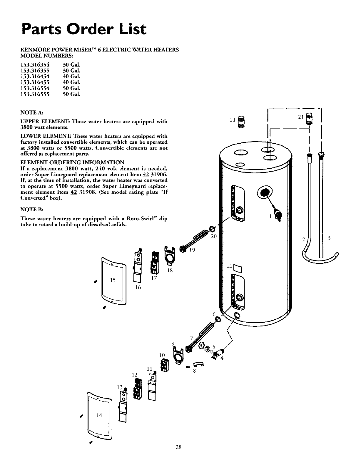
Parts Order List
KENMORE POWER MISER rM6 ELECTRIC WATER HEATERS
MODEL NUMBERS:
153.316354 30 Gal.
153.316355 30 Gal.
153.316454 40 Gal.
153.316455 40 Gal.
153.316554 50 Gal.
153.316555 50 Gal.
NOTE A:
UPPER ELEMENT: These water heaters are equipped with
3800 watt elements.
LOWER ELEMENT: These water heaters are equipped with
factory installed convertible elements, which can be operated
at 3800 watts or 5500 watts. Convertible elements are not
offered as replacement parts.
ELEMENT ORDERING INFORMATION
If a replacement 3800 watt, 240 volt element is needed,
order Super Limeguard replacement element Item 42 31906.
If, at the time of installation, the water heater was converted
to operate at 5500 watts, order Super Limeguard replace-
ment element Item 42 31908. (See model rating plate "If
Converted" box).
NOTE B:
These water heaters are equipped with a Roto-Swirl _ dip
tube to retard a build-up of dissolved solids.
6
10
28
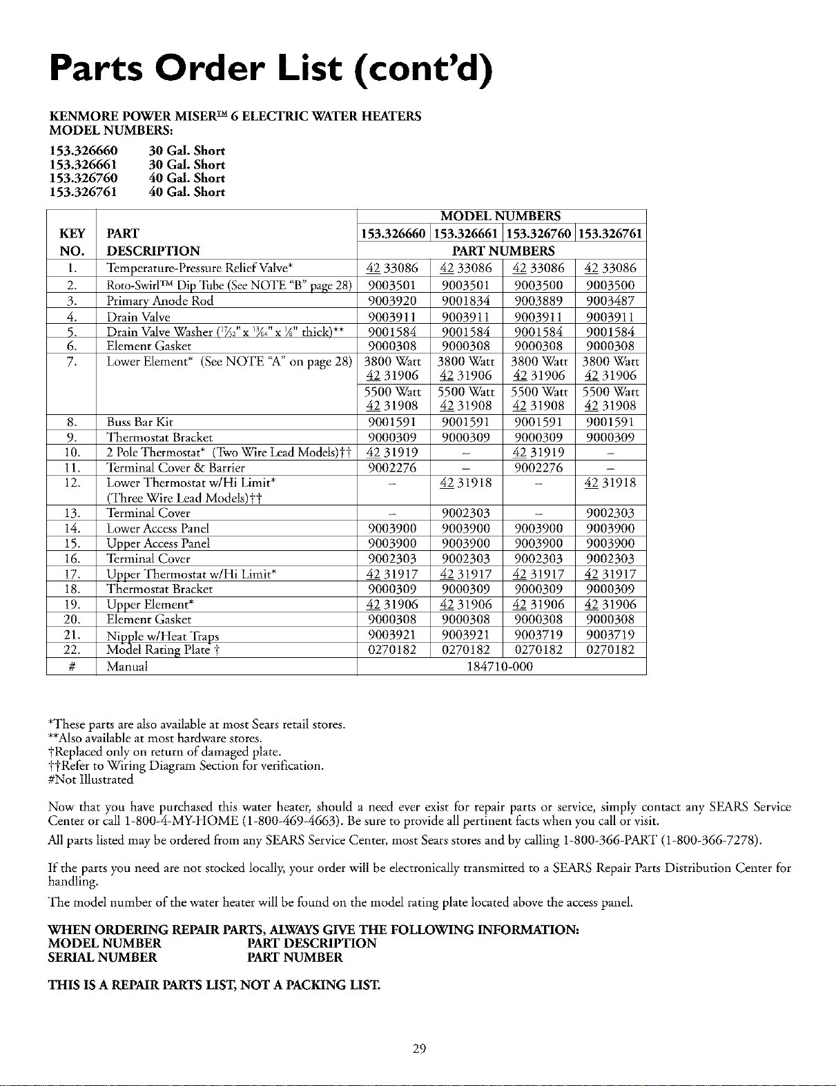
Parts Order List (cont'd)
KENMORE POWER MISERTM 6ELECTRIC WATER HEATERS
MODEL NUMBERS:
153.326660 30 Gal. Short
153.326661 30 Gal. Short
153.326760 40 Gal. Short
153.326761 40 Gal. Short
KEY PART
NO. DESCRIPTION
1. _l_mperature-Pressure Relief Valve*
2. Roto-SwirlTM Dip "lhbe(SeeNOTE "B" page28)
3. Primary Anode Rod
4. Drain Valve
5. Drain ValveWasher (_7_2"x_/'x _" thick)**
6. Element Gasket
7. Lower Element* (See NOTE "A"on page 28)
153.326660 153.326761
Buss Bar Kit
Thermostat Bracket
2 PoleThermostat* (Two Wire Lead Mo&Is)tt
_l_rminal Cover & Barrier
Lower Thermostat w/Hi Limit*
(Three Wire Lead Models)t_
13. _I_rminalCover
14. Lower AccessPanel
15. Upper Access Panel
16. _I_rminalCover
17. Upper Thermostat w/Hi Limit*
18. Thermostat Bracket
19. Upper Element*
20. Element Gasket
21. Nipple w/Heat _I]'aps
22. Model Rating Plate t
# Manual
8.
9.
10.
11.
12. 42 31918
4233086
9003501
9003920
9003911
9001584
9000308
3800Watt
4231906
5500Watt
4231908
9001591
9000309
4231919
9002276
9003900
9003900
9002303
4231917
9000309
4231906
9000308
9003921
0270182
MODEL NUMBERS
153.326661 153.326760
PART NUMBERS
42 33086 42 33086
9003501 9003500
9001834 9003889
9003911 9003911
9001584 9001584
9000308 9000308
3800Watt 3800Watt
42 31906 42 31906
5500Watt 5500Watt
42 31908 42 31908
9001591 9001591
9000309 9000309
42 31919
9002276
42 31918 -
9002303 -
9003900 9003900
9003900 9003900
9002303 9002303
42 31917 42 31917
9000309 9000309
42 31906 42 31906
9000308 9000308
9003921 9003719
0270182 0270182
184710-000
42 33086
9003500
9003487
9003911
9001584
9000308
3800Watt
42 319O6
5500Watt
42 31908
9001591
9000309
9002303
9003900
9003900
9002303
4231917
9000309
4231906
9000308
9003719
0270182
*These parts are also available at most Sears retail stores.
**Alsoavailable at most hardware stores.
yReplaced only on return of damaged plate.
yyRel:er to Wiring Diagram Section for verification.
#Not Illustrated
Now that you have purcha_sed this water heater, should a need ever exist for repair parts or service, simply contact any SEARS Service
Center or call 1-800-4-MY-HOME (1-800-469-4663). Be sure to provide all pertinent facts when you call or visit.
All parts listed may be ordered from any SEARS Service Center, most Sears stores and by calling 1-800-366-PART (1-800-366-7278).
If the parts you need are not stocked locally, your order will be electronically transmitted to a SEARS Repair Parts Distribution Center for
handling.
The model number of the water heater will be found on the model rating plate located above the access panel.
WHEN ORDERING REPAIR PARTS,ALWAYSGIVE THE FOLLOWING INFORMATION:
MODEL NUMBER PART DESCRIPTION
SERIAL NUMBER PART NUMBER
THIS IS A REPAIR PARTS LIST,NOT A PACKING LIST.
29
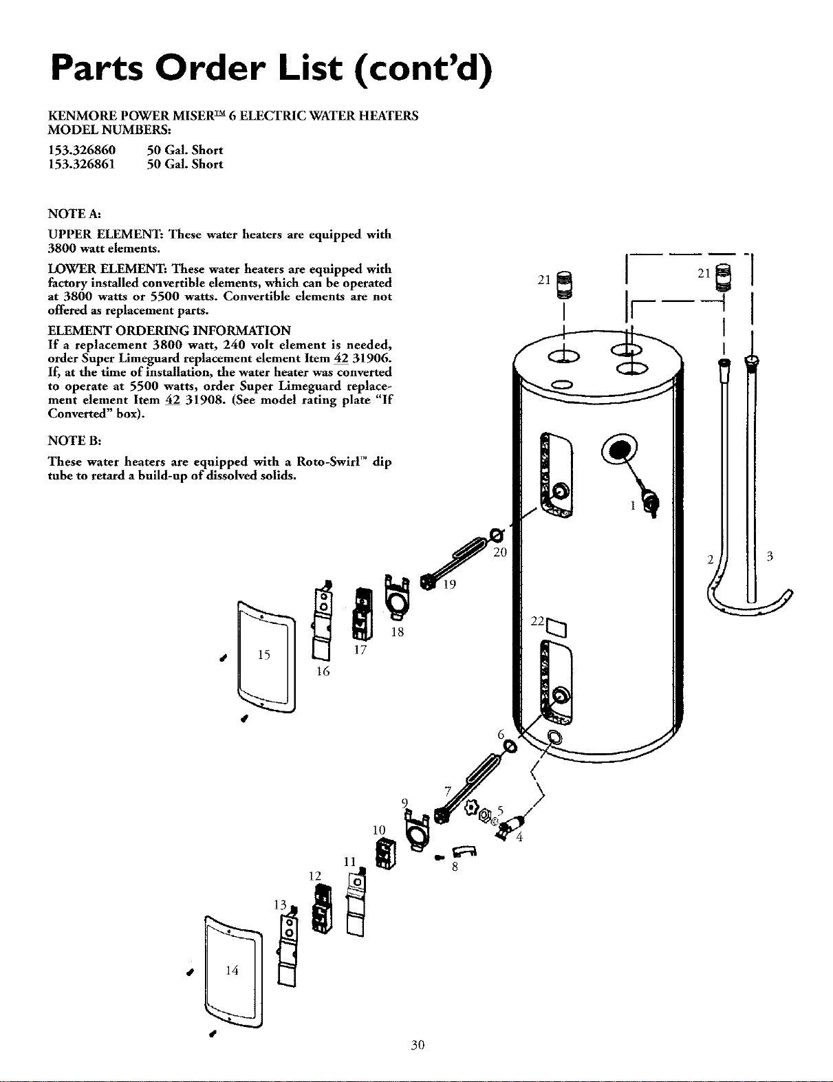
Parts Order List (cont'd)
KENMORE POWER MISER rM6ELECTRIC WATER HEATERS
MODEL NUMBERS:
153.326860 50 Gal. Short
153.326861 50 Gal. Short
NOTE A:
UPPER ELEMENT: These water heaters are equipped with
3800 watt elements.
LOWER ELEMENT: These water heaters are equipped with
factory installed convertible elements, which can be operated
at 3800 watts or 5500 watts. Convertible elements are not
offered as replacement parts.
ELEMENT ORDERING INFORMATION
If a replacement 3800 watt, 240 volt element is needed,
order Super Limeguard replacement element Item 42 31906.
If, at the time of installation, the water heater was converted
to operate at 5500 watts, order Super Limeguard replace-
ment element Item 42 31908. (See model rating plate "If
Converted" box).
NOTE B:
These water heaters are equipped with aRoto-Swirl _dip
tube to retard a build-up of dissolved solids.
6
10
30
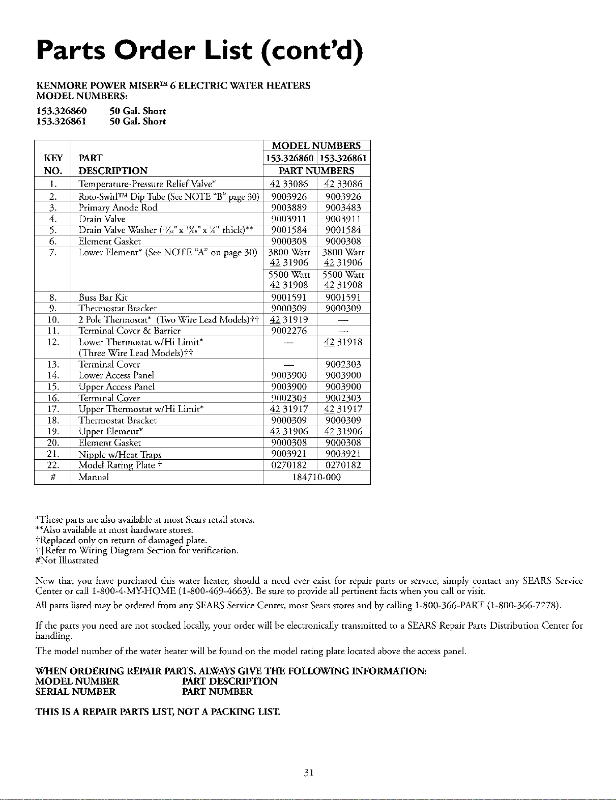
Parts Order List (cont'd)
KENMOREPOWERMISER TM 6ELECTRIC WATERHEATERS
MODEL NUMBERS:
153.326860 50GM. Short
153.326861 50GM. Short
KEY PART
NO. DESCRIPTION
1. _l_mperature-Pressure Relief Valve*
2. Roto-SwirlTM Dip "lhbe(SeeNOTE "B" page 30)
3. Primary Anode Rod
4. Drain Valve
5. Drain ValveWasher (_/_2"xI_,/'x gs"thick)**
6. Element Gasket
7. Lower Element* (See NOTE "A" on page 30)
8. Buss Bar Kit
9. Thermostat Bracket
10. 2 PoleThermostat* (Two x?U,re Lead Models)it
11. _l_rminal Cover & Barrier
12. Lower Thermostat w/Hi Limit*
(Three Wire Lead Models)t_
13. _I_rminalCover
14. Lower AccessPanel
15. Upper Access Panel
16. _I_rminalCover
17. Upper Thermostat w/Hi Limit*
18. Thermostat Bracket
19. Upper Element*
20. Element Gasket
21. Nipple w/Heat "_(i'aps
22. Model Rating Plate t
# Manual
MODEL NUMBERS
153.326860 153.326861
PART NUMBERS
42 33086 42 33086
9003926 9003926
9003889 9003483
9003911 9003911
9001584 9001584
9000308 9000308
3800Watt 3800Watt
42 31906 42 31906
5500Watt 5500Watt
42 31908 42 31908
9001591 9001591
9000309 9000309
42 31919 --
9002276 --
-- 42 31918
-- 9002303
9003900 9003900
9003900 9003900
9002303 9002303
42 31917 42 31917
9000309 9000309
42 31906 42 31906
9000308 9000308
9003921 9003921
0270182 0270182
184710-000
*These parts are also available at most Sears retail stores.
**Alsoavailable at most hardware stores.
yReplaced only on return of damaged plate.
y'_Rel:erto Wiring Diagram Section for veril]cation.
#Not Illustrated
Now that you have purcha_sed this water heater, should a need ever exist for repair parts or service, simply contact any SEARS Service
Center or call 1-800-4-MY-HOME (1-800-469-4663). Be sure to provide all pertinent facts when you call or visit.
All parts listed may be ordered from any SEARS Service Center, most Sears stores and by calling 1-800-366-PART (1-800-366-7278).
If the parts you need are not stocked locally, your order will be electronically transmitted to a SEARS Repair Parts Distribution Center for
handling.
The model number of the water heater will be found on the model rating plate located above the access panel.
WHEN ORDERING REPAIR PARTS,ALWAYSGIVE THE FOLLOWING INFORMATION:
MODEL NUMBER PART DESCRIPTION
SERIAL NUMBER PART NUMBER
THIS IS A REPAIR PARTS LIST,NOT A PACKING LIST.
31
FULL ONE YF_R WARRANTY ON WATER HEAFER
For one year from the date of purchase, when your Sears Kenmore water heater is installed and operated in a slngle-family residence in
accordance with the instructions in this manual, Sears will:
1. Repair defects in material or workmanship in this water heater, free of charge.
2. Furnish and install a new current model water heater of equal capacity and quality, free of charge, if a leak occurs in the tank.
LIMITED WARIL4N'IT ON "[ANKSTHAT LEAK
After one year and through 6 years from the date of purchase for water heaters used in a single-family residence, ifa leak occurs in the
tank, Searswill furnish a new current model water heater of equal capacity and quality. You will be charged for any installation.
LIMITED WARRAN'Ft' ON PARTS
After one year and through 6 years from the date of purchase, when your Sears Kenmore water heater is used in a single-family
residence and is installed and operated in accordance with the information in this manual, ifa part fails due to a materials or
workmanship, Sears will furnish a replacement free of charge. You will be charged for labor.
if the water heater is subjected to commercial, institutional, industrial or use in residences of two families or more, the above warranty
coverage for tanks that leak is effective for 2 years from the date of purchase and the above parts warranty is effective for 1 year from the
date of purchase.
"Ibobtain warranty service, SIMPLY CALL 1-800-4MY-HOME (1-800-469-4663). "This warranty applies only while this product is
in use in the United States."
"]['hiswarranty gives you specific legal rights and you may also have other rights which vary from state to state.
SEARS, ROEBUCK AND CO., Dept. 817 WA, HOFFMAN ESTATES, IL 6(1179
The price of your water heater does not include a free checkup service call. On water heater installations arranged by Sears, Searswarrants the installation.
Acharge will be made on service calls due to poor or incomplete installation. These include:
a. Adjusting thermostat b. Leaks in pipes or fittings c. Condensation
MASTER PROTECTION AGREEMENTS
Congratulationson makinga smartpurchase.Yorenew Kenmor4_prod-
uct isdesignedand manufactured foryearsof dependableoperation. But
llke all products, it may require preventivemaintenanceor repair from
time to time. That's when having a Master Protection Agreementcan
saveyoumoneyand aggravation.
Purchasea Master ProtectionAgreementnowand protect yourselffrom
unexpectedhassleand expense.
)
"l]leMasterI rotectionAgreementalsohelpsextendthe lifeofyournew
product. Here'swhat'sincludedin theAgreement:
•ExpertServiceby our 12,000professionalrepairspecialists.
•Unlimitedservice and no chargefor partsand laboron allcovered
repairs.
• "No-lemon" _tee - replacementof yourcoveredproduct iffour
or more productfailuresoccurwithin twelvemonths.
•Productreplacementifyourcoveredproductcan'tbefixed.
• Annual PreventiveMaintenance Check at your request - no extra
charge.
•Fast help by phone - phone support from a Sears technician on
products requiring in-home repair, plus convenient repair scheduling.
•Power surge protection against electricaldamage due to power fluc-
tuations.
•Rental reimbursement if repair of your covered product takes longer
than promised.
Once youpurchasetheAgreement,a simplephonecallis allthat it takes
foryou to scheduleservice.Youcan callanytimeday or night, or sched-
ule aserviceappointment on-fine.
Searshas over 12,000 professionalrepair spedafists,who haveaccessto
over4.5 million qualityparts and accessories.That's the kind of profes-
sionalismyoucancount on to helpprolong the llfeofyournewpurchase
foryearsm come.PurchaseyourMasterProtectionAgreementtoday!
Some limitations and exclusions apply. For prices and additional
information call 1-800-82%6655
SEARS INSTALLATION SERVICE
ForSearsprofessionalinstallationofhome appliances,garagedooropen-
ers, water heaters and other major home items, in the U.S.A., call
1-800-4-MY-HOME®.
For in-home major brand repair service
Call 24 hours a day, 7 days a week (USA and Canada)
1-800-4-MY-HOME ®
(I-800-469-4663)
v_vw.sears.eom
The modelnumber ofyour waterheater isfound on the modelrating plateon the front ofthe waterheater.
Sears, Roebuck and Co., Hoffman Estates, Ik 60179 U.S.A.