Use & Care Guide
Model No.
153.321344 30 Gallon
153.321444 40 Gallon
153.321544 55 Gallon
153.321644 66 Gallon
153.321844 80 Gallon
I<enmore® LOW LEAD
CONTENT
:lec'r°c
For potable water heating only.
Not suitable for space heating.
INSTALLER: Affix these instructions to or near
the water heater.
OWNER: Retain these instructions for future
reference.
Si no puede leer o entender el ingles y necesita el manual de
instrucciones en espaSol, puede solicitarlo al 1-800-821-2017. NO
TRATE DE INSTALAR U OPERAR ESTE CALENTADOR DE AGUA
Sl NO ENTIENDE LAS INSTRUCCIONES. No hacer caso de esta
advertencia podria originar lesiones graves o mortales.
P/N 326123-000 (0313)
Sears Brands Management Corporation,
Hoffman Estates, IL 60179 U.S.A.
www.kenmore.com
www.sears.com
Your safety and the safety of others is extremely important in the installation, use and servicing of this water heater.
Many safety-related messages and instructions have been provided in this manual and on your own water heater to warn
you and others of a potential injury hazard. Read and obey all safety messages and instructions throughout this manual.
It is very important that the meaning of each safety message is understood by you and others who install, use or service
this water heater.
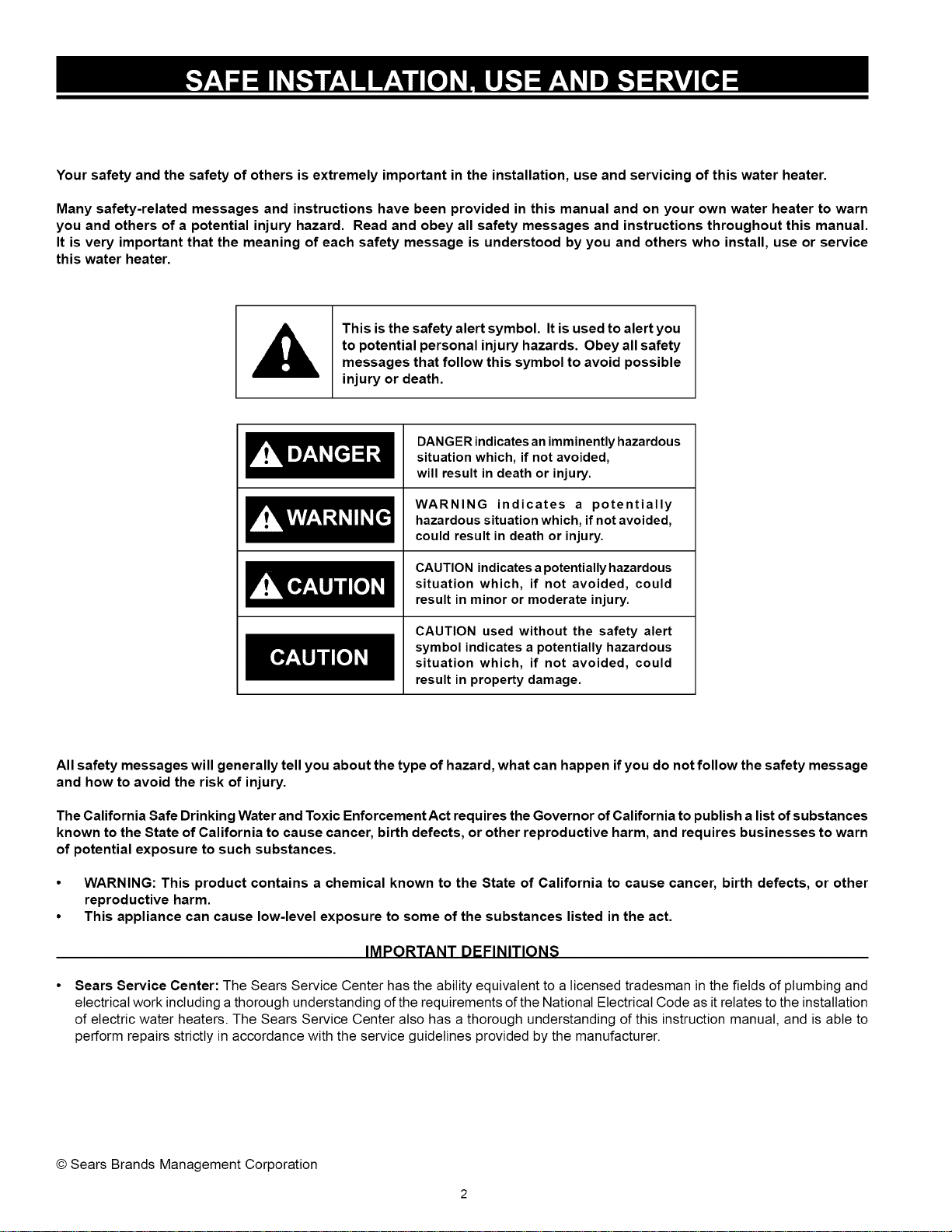
This is the safety alert symbol. It is used to alert you
to potential personal injury hazards. Obey all safety
messages that follow this symbol to avoid possible
injury or death.
__.I. ZEZ!
__.l!ZI.'.Z
DANGER indicatesan imminently hazardous
situation which, if not avoided,
will result in death or injury.
WARNING indicates a potentially
hazardous situation which, if not avoided,
could result in death or injury.
CAUTION indicatesa potentially hazardous
situation which, if not avoided, could
result in minor or moderate injury.
CAUTION used without the safety alert
symbol indicates a potentially hazardous
situation which, if not avoided, could
result in property damage.
All safety messages will generally tell you about the type of hazard, what can happen if you do not follow the safety message
and how to avoid the risk of injury.
The California Safe Drinking Water and Toxic Enforcement Act requires the Governor of California to publish a list ofsubstances
known to the State of California to cause cancer, birth defects, or other reproductive harm, and requires businesses to warn
of potential exposure to such substances.
• WARNING: This product contains a chemical known to the State of California to cause cancer, birth defects, or other
reproductive harm.
• This appliance can cause low-level exposure to some of the substances listed in the act.
IMPORTANT DEFINITIONS
Sears Service Center: The Sears Service Center has the ability equivalent to a licensed tradesman in the fields of plumbing and
electrical work including athorough understanding of the requirements of the National Electrical Code as it relates to the installation
of electric water heaters. The Sears Service Center also has a thorough understanding of this instruction manual, and is able to
perform repairs strictly in accordance with the service guidelines provided by the manufacturer.
© Sears Brands Management Corporation
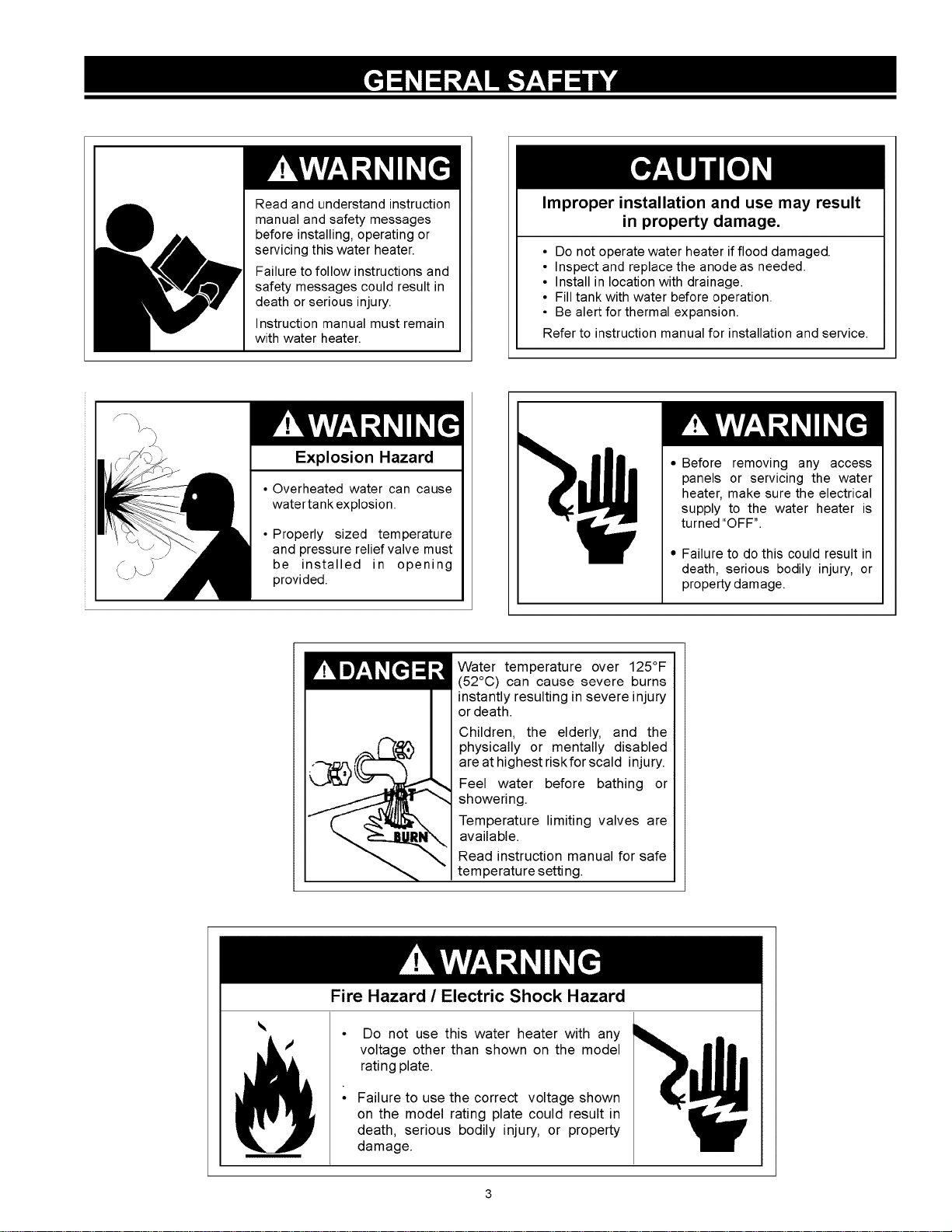
Readandunderstandinstruction
manualandsafetymessages
beforeinstalling,operatingor
servicingthiswaterheater.
Failuretofollowinstructionsand
safetymessagescouldresultin
deathorseriousinjury.
Instructionmanualmustremain
withwaterheater.
Improper installation and use may result
in property damage.
• Do not operate water heater if flood damaged.
• Inspect and replace the anodeas needed.
• Install in location with drainage.
• Fill tank with water before operation.
• Be alert for thermal expansion.
Refer to instruction manual for installation and service.
Explosion Hazard
• Overheated water can cause
watertank explosion.
• Properly sized temperature
and pressure relief valve must
be installed in opening
provided.
•Before removing any access
panels or servicing the water
heater, make sure the electrical
supply to the water heater is
turned "OFF".
•Failure to do this could result in
death, serious bodily injury, or
property damage.
Water temperature over 125°F
(52°C) can cause severe burns
instantly resulting in severe injury
or death.
Children, the elderly, and the
physically or mentally disabled
are at highest riskfor scald injury.
Feel water before bathing or
showering.
Temperature limiting valves are
available.
Read instruction manual for safe
temperature setting.
_i_ •Do not use this water heater with any
voltage other than shown on the model
rating plate.
•Failure to use the correct voltage shown
on the model rating plate could result in
death, serious bodily injury, or property
damage.
Fire Hazard /Electric Shock Hazard
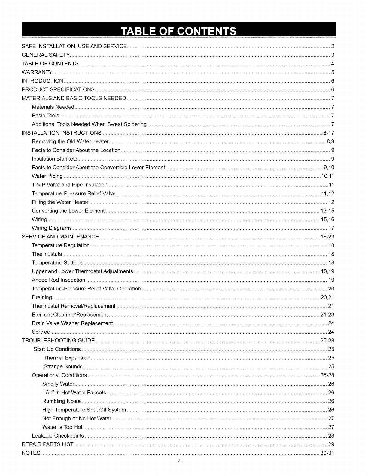
SAFE INSTALLATION, USE AND SERVICE ...................................................................................................................................... 2
GENERAL SAFETY ............................................................................................................................................................................ 3
TABLE OF CONTENTS ...................................................................................................................................................................... 4
WARRANTY ....................................................................................................................................................................................... 5
INTRODUCTION ................................................................................................................................................................................ 6
PRODUCT SPECIFICATIONS ........................................................................................................................................................... 6
MATERIALS AND BASIC TOOLS NEEDED ...................................................................................................................................... 7
Materials Needed ......................................................................................................................................................................... 7
Basic Tools ................................................................................................................................................................................... 7
Additional Tools Needed When Sweat Soldering ........................................................................................................................ 7
INSTALLATION INSTRUCTIONS .................................................................................................................................................. 8-17
Removing the Otd Water Heater ................................................................................................................................................ 8,9
Facts to Consider About the Location ........................................................................................................................................... 9
Insulation Blankets ........................................................................................................................................................................ 9
Facts to Consider About the Convertible Lower Element ........................................................................................................ 9,10
Water Piping ........................................................................................................................................................................... 10,11
T & P Valve and Pipe Insulation ................................................................................................................................................... 11
Temperature-Pressure Relief Valve ........................................................................................................................................ 11,12
Filling the Water Heater .............................................................................................................................................................. 12
Converting the Lower Element .............................................................................................................................................. 13-15
Wiring .................................................................................................................................................................................... 15,16
Wiring Diagrams ......................................................................................................................................................................... 17
SERVICE AND MAINTENANCE .................................................................................................................................................. 18-23
Temperature Regulation ............................................................................................................................................................. 18
Thermostats ................................................................................................................................................................................ 18
Temperature Settings .................................................................................................................................................................. 18
Upper and Lower Thermostat Adjustments ........................................................................................................................... 18,19
Anode Rod Inspection ................................................................................................................................................................ 19
Temperature-Pressure Relief Valve Operation ........................................................................................................................... 20
Draining ................................................................................................................................................................................. 20,21
Thermostat Removal/Replacement ............................................................................................................................................ 21
Element Cleaning/Replacement ............................................................................................................................................ 21-23
Drain Valve Washer Replacement .............................................................................................................................................. 24
Service ........................................................................................................................................................................................ 24
TROUBLESHOOTING GUIDE ..................................................................................................................................................... 25-28
Start Up Conditions ................................................................................................................................................................... 25
Thermal Expansion ............................................................................................................................................................. 25
Strange Sounds .................................................................................................................................................................. 25
Operational Conditions .......................................................................................................................................................... 25-28
Smelly Water ........................................................................................................................................................................ 26
"Air" in Hot Water Faucets .................................................................................................................................................. 26
Rumbling Noise ................................................................................................................................................................... 26
High Temperature Shut Off System ..................................................................................................................................... 26
Not Enough or No Hot Water ............................................................................................................................................... 27
Water Is Too Hot .................................................................................................................................................................. 27
Leakage Checkpoints ................................................................................................................................................................. 28
REPAIR PARTS LIST ........................................................................................................................................................................ 29
NOTES ......................................................................................................................................................................................... 30-31
4
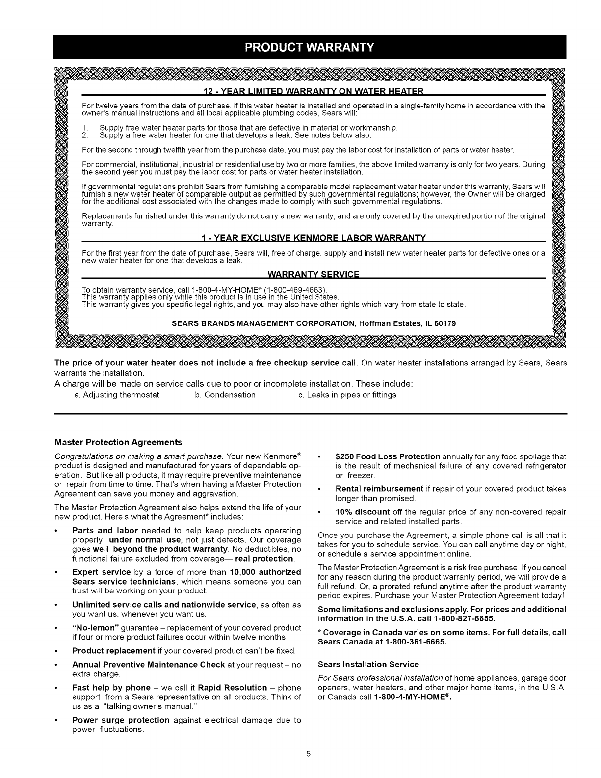
12 -YEAR LIMITED WARRANTY ON WATER HEATER
For twelve years from the date of purchase, if this water heater is installed and operated in a single-family home in accordance with the
owner's manual instructions and all local applicable plumbing codes, Sears will:
1. Supply free water heater parts for those that are defective in material or workmanship.
2. Supply a free water heater for one that develops a leak. See notes below also.
For the second through twelfth year from the purchase date, you must pay the labor cost for installation of parts or water heater.
For commercial, institutional, industrial or residential use by two or more families, the above limited warranty is only for two years. During
the second year you must pay the labor cost for parts or water heater installation.
Ifgovernmental regulations prohibit Sears from furnishing a comparable model replacement water heater under this warranty, Sears will
furnish a new water heater of comparable output as permitted by such governmental regulations; however, the Owner will be charged
for the additional cost associated with the changes made to comply with such governmental regulations.
Replacements furnished under this warranty do not carry a new warranty; and are only covered by the unexpired portion of the original
warranty.
1 -YEAR EXCLUSIVE KENMORE LABOR WARRANTY
For the first year from the date of purchase, Sears will, free of charge, supply and install new water heater parts for defective ones or a
new water heater for one that develops a leak.
WARRANTY SERVICE
®
To obtain warranty service, call 1-800-4-MY-HOME (1-800-469-4663).
This warranty applies only while this product is in use in the United States.
This warranty gives you specific lega/rights, and you may also have other rights which vary from state to state.
SEARS BRANDS MANAGEMENT CORPORATION, Hoffman Estates, IL 60179
The price of your water heater does not include a free checkup service call. On water heater installations arranged by Sears, Sears
warrants the installation.
A charge will be made on service calls due to poor or incomplete installation. These include:
a. Adjusting thermostat b. Condensation c. Leaks in pipes or fittings
Master Protection Agreements
Congratulations on making a smart purchase. Your new Kenmore ®
product is designed and manufactured for years of dependable op-
eration. But like all products, it may require preventive maintenance
or repair from time to time. That's when having a Master Protection
Agreement can save you money and aggravation.
The Master Protection Agreement also helps extend the life of your
new product. Here's what the Agreement* includes:
• Parts and labor needed to help keep products operating
properly under normal use, not just defects. Our coverage
goes well beyond the product warranty. No deductibles, no
functional failure excluded from coverage-- real protection.
• Expert service by a force of more than 10,000 authorized
Sears service technicians, which means someone you can
trust will be working on your product.
• Unlimited service calls and nationwide service, as often as
you want us, whenever you want us.
• "No-lemon" guarantee - replacement of your covered product
if four or more product failures occur within twelve months.
• Product replacement if your covered product can't be fixed.
• Annual Preventive Maintenance Check at your request - no
extra charge.
• Fast help by phone - we call it Rapid Resolution - phone
support from a Sears representative on all products. Think of
us as a "talking owner's manual."
• Power surge protection against electrical damage due to
power fluctuations.
$250 Food Loss Protection annually for any food spoilage that
is the result of mechanical failure of any covered refrigerator
or freezer.
•Rental reimbursement if repair of your covered product takes
longer than promised.
• 10% discount off the regular price of any non-covered repair
service and related installed parts.
Once you purchase the Agreement, a simple phone call is all that it
takes for you to schedule service. You can call anytime day or night,
or schedule a service appointment online.
The Master Protection Agreement is a risk free purchase. If you cancel
for any reason during the product warranty period, we will provide a
full refund. Or, a prorated refund anytime after the product warranty
period expires. Purchase your Master Protection Agreement today!
Some limitations and exclusions apply. For prices and additional
information in the U.S.A. call 1-800-827-6655.
* Coverage in Canada varies on some items. For full details, call
Sears Canada at 1-800-361-6665.
Sears Installation Service
For Sears professional installation of home appliances, garage door
openers, water heaters, and other major home items, in the U.S.A.
or Canada call 1-800-4-MY-HOME ®.
Thank You for purchasing a Sears water heater. Properly
installed and maintained, it should give you years of trouble free
service. It is strongly suggested that this new water heater be
professionally installed, contact the local Sears Service Center or
any Sears store. They wilt arrange for prompt, quality installation
by Sears authorized contractors.
is available from your local government or public library or
electric company or bywriting Underwriters Laboratories Inc.,
333 Pfingsten Road, Northbrook, IL 60062.
If after reading this manual you have any questions or do not
understand any portion of the instructions, call Sears Service
Center.
Abbreviations Found In This Instruction Manual:
UL- Underwriters Laboratories Inc.
•The product is certifield to comply with a maximum weighted
average of 0.25% lead content as required in some areas.
NEC - National Electrical Code
ANSI-American National Standards Institute
Carefully plan the place where you are going to put the water
heater. Correct electrical wiring and connections are very
important in preventing death from possible electrical shock
and fires.
Read the "General Safety" section, page 3 of this manual
first and then the entire manual carefully. If you don't follow
the safety rules, the water heater wilt not operate properly. It
could cause DEATH, SERIOUS BODILY INJURY AND/OR
PROPERTY DAMAGE.
• Keep combustibles such as boxes, magazines, clothes, etc.,
away from water heater area.
Examine the location to ensure the water heater complies with
the "Facts to Consider About the Location" section.
This manual contains instructions for the installation,
operation, and maintenance of this electric water heater. It
also contains warnings throughout the manual that you must
read and be aware of. All warnings and all instructions are
essential to the proper operation of the water heater and your
safety. Since we cannot put everything on the first few pages,
READ THIS ENTIRE MANUAL BEFORE ATTEMPTING TO
INSTALL OR OPERATE THE WATER HEATER.
The installation must conform with the instructions in this
manual; electric company rules; and Local Codes, or in
the absence of Local Codes, with the current edition of the
NEC - National Electrical Code, NFPA 70. This publication
For California installation, this water heater must be braced,
anchored, or strapped to avoid falling or moving during an
earthquake. See instructions for correct installation procedures.
Instructions may be obtained from California's Office of
the State Architect, 1102 Q Street, Suite 5100, Sacramento,
CA 95811. Instructions can also be downloaded to your computer
at www.dsa.dgs.ca.gov/Pubs.
Massachusetts Code requires this water heater to be installed
in accordance with Massachusetts 248-CMR 2.00; State
Plumbing Code and 248-CMR 5.00. In the Commonwealth of
Massachusetts, this product must be installed by a licensed
plumber or gasfitter.
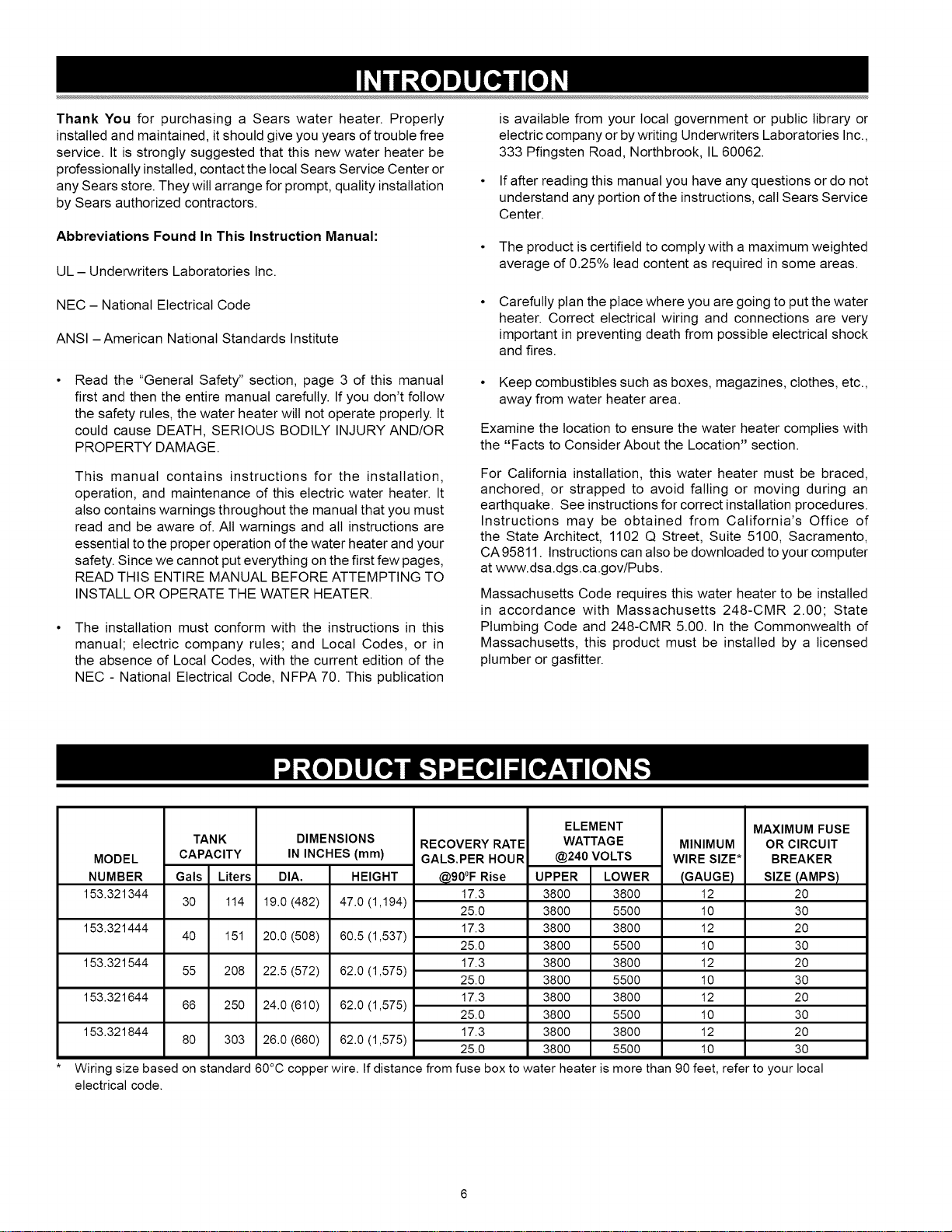
MODEL
NUMBER
153.321344
153.321444
153.321544
153.321644
153.321844
TANK
CAPACITY
Gals Liters
30 114
40 151
55 208
66 250
80 303
DIMENSIONS
IN INCHES (mm)
DIA, HEIGHT
19.0 (482) 47.0 (1,194)
20.0 (508) 60.5 (1,537)
22.5 (572) 62.0 (1,575)
24.0 (610) 62.0 (1,575)
26.0 (660) 62.0 (1,575)
ELEMENT
RECOVERY RATE WATTAGE
GALS.PER HOUR @240 VOLTS
@90°F Rise UPPER LOWER
173 3800 3800
25.0 3800 5500
17.3 3800 3800
25.0 3800 5500
17.3 3800 3800
25.0 3800 5500
17.3 3800 3800
25.0 3800 5500
17.3 3800 3800
25.0 3800 5500
MINIMUM
WIRE SIZE*
(GAUGE)
12
10
12
10
12
10
12
10
12
10
MAXIMUM FUSE
OR CIRCUIT
BREAKER
SIZE (AMPS)
2O
3O
2O
3O
2O
3O
2O
3O
2O
3O
Wiring size based on standard 60°C copper wire. If distance from fuse box to water heater is more than 90 feet, refer to your local
electrical code.
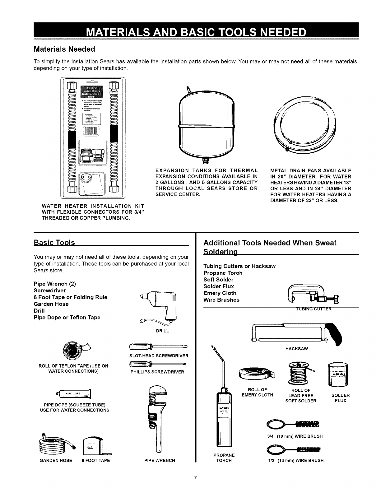
Materials Needed
To simplify the installation Sears has available the installation parts shown below. You may or may not need all of these materials,
depending on your type of installation.
WATER HEATER INSTALLATION KIT
WITH FLEXIBLE CONNECTORS FOR 3/4"
THREADED OR COPPER PLUMBING.
EXPANSION TANKS FOR THERMAL
EXPANSION CONDITIONS AVAILABLE IN
2 GALLONS , AND 5 GALLONS CAPACITY
THROUGH LOCAL SEARS STORE OR
SERVICE CENTER.
METAL DRAIN PANS AVAILABLE
IN 20" DIAMETER FOR WATER
HEATERS HAVING A DIAMETER 18"
OR LESS AND IN 24" DIAMETER
FOR WATER HEATERS HAVING A
DIAMETER OF 22" OR LESS.
Basic Tools
You may or may not need alt of these tools, depending on your
type of installation. These tools can be purchased at your local
Sears store.
Pipe Wrench (2)
Screwdriver
6 Foot Tape or Folding Rule _L. jIll}
Garden Hose
Drill
Pipe Dope or Teflon Tape
DRILL
SLOT-HEAD SCREWDRIVER
ROLL OF TEFLON TAPE (USE ON J
WATER CONNECTIONS) PHILLIPS SCREWDRIVER
PIPE DOPE (SQUEEZE TUBE)
USE FOR WATER CONNECTIONS
GARDEN HOSE 6FOOT TAPE PIPE WRENCH
Additional Tools Needed When Sweat
Solderino
Tubing Cutters or Hacksaw
Propane Torch
Soft Solder
Solder Flux
Emery Cloth
Wire Brushes
_U Biii,,_ _UTT_R
\i
PROPANE
TORCH
ROLLOF
EMERY CLOTH
HACKSAW
ROLLOF
LEAD-FREE
SOFTSOLDER
3/4" (19 mm)WIRE BRUSH
C>-===,
1/2" (13 mm)WIRE BRUSH
B
SOLDER
FLUX
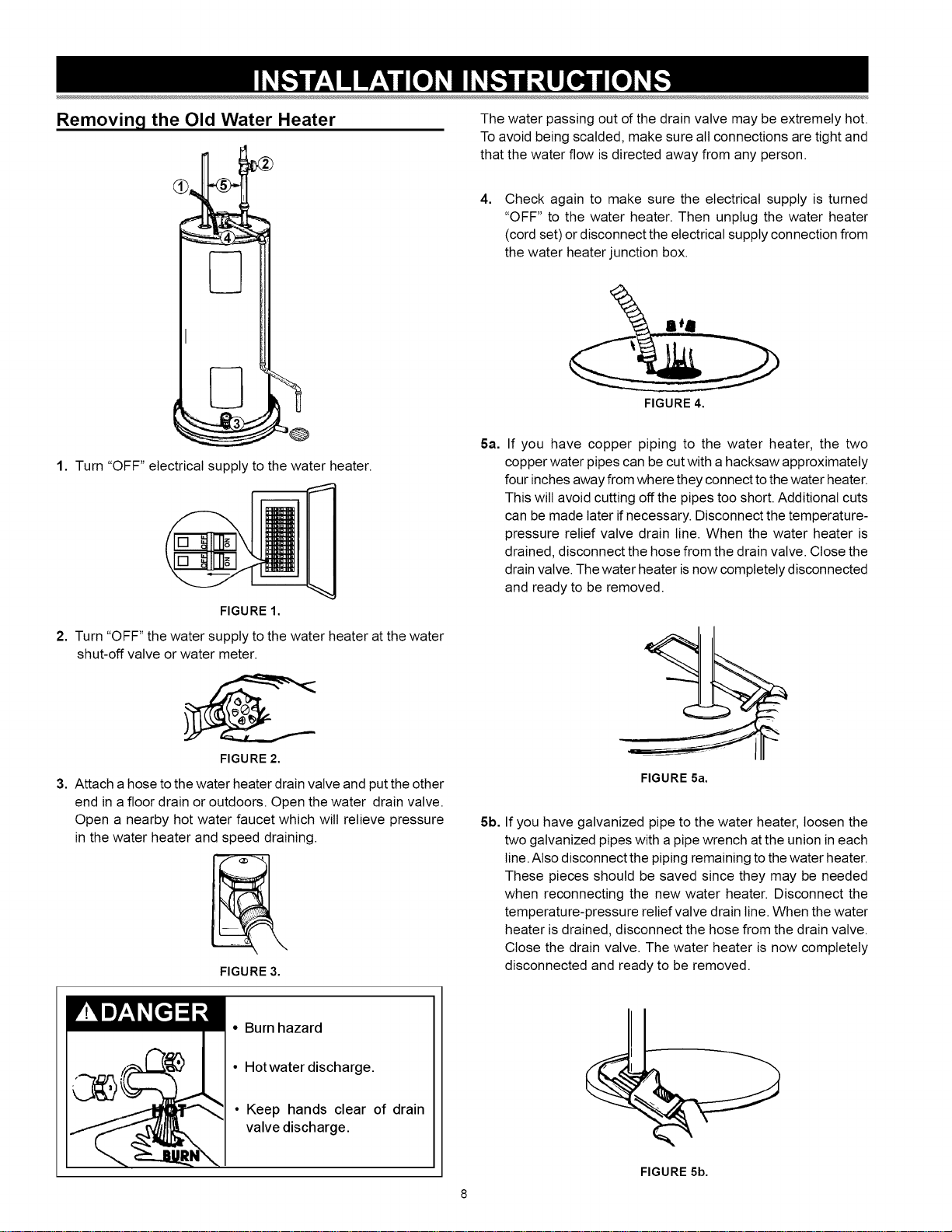
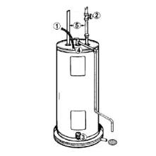
Removing the Old Water Heater
1. Turn "OFF" electrical supply to the water heater.
The water passing out of the drain valve may be extremely hot.
To avoid being scalded, make sure all connections are tight and
that the water flow is directed away from any person.
4, Check again to make sure the electrical supply is turned
"OFF" to the water heater. Then unplug the water heater
(cord set) or disconnect the electrical supply connection from
the water heater junction box.
FIGURE 4.
5a, If you have copper piping to the water heater, the two
copper water pipes can be cut with a hacksaw approximately
four inches away from where they connect to the water heater.
This wilt avoid cutting off the pipes too short. Additional cuts
can be made later if necessary. Disconnect the temperature-
pressure relief valve drain line. When the water heater is
drained, disconnect the hose from the drain valve. Close the
drain valve. The water heater is now completely disconnected
and ready to be removed.
FIGURE 1.
2. Turn "OFF" the water supply to the water heater at the water
shut-off valve or water meter.
FIGURE 2.
3. Attach a hose to the water heater drain valve and put the other
end in afloor drain or outdoors. Open the water drain valve.
Open a nearby hot water faucet which will relieve pressure
in the water heater and speed draining.
FIGURE 3,
FIGURE 5a.
5b. If you have galvanized pipe to the water heater, loosen the
two galvanized pipes with a pipe wrench at the union in each
line. Also disconnect the piping remaining to the water heater.
These pieces should be saved since they may be needed
when reconnecting the new water heater. Disconnect the
temperature-pressure relief valve drain line. When the water
heater is drained, disconnect the hose from the drain valve.
Close the drain valve. The water heater is now completely
disconnected and ready to be removed.
•Burn hazard
•Hotwater discharge.
• Keep hands clear of drain
valve discharge.
FIGURE 5b.
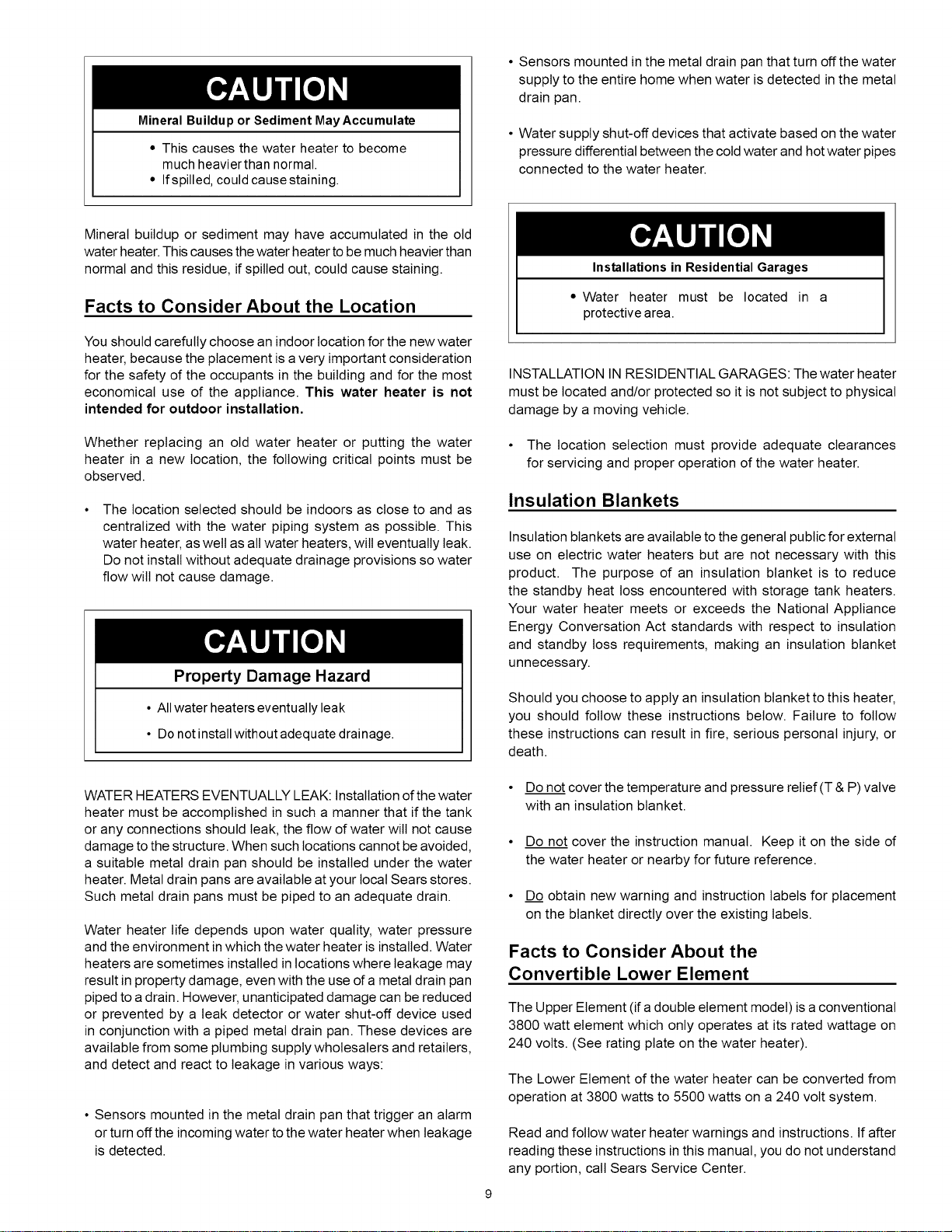
MineralBuilduporSedimentMayAccumulate
• This causes the water heater to become
much heavier than normal.
• Ifspilled, could causestaining.
• Sensors mounted in the metal drain pan that turn offthe water
supply to the entire home when water is detected in the metal
drain pan.
• Water supply shut-off devices that activate based on the water
pressure differential between the cold water and hot water pipes
connected to the water heater.
Mineral buildup or sediment may have accumulated in the old
water heater. This causes the water heater to be much heavier than
normal and this residue, if spilled out, could cause staining.
Facts to Consider About the Location
You should carefully choose an indoor location for the new water
heater, because the placement is a very important consideration
for the safety of the occupants in the building and for the most
economical use of the appliance. This water heater is not
intended for outdoor installation.
Whether replacing an old water heater or putting the water
heater in a new location, the following critical points must be
observed.
The location selected should be indoors as close to and as
centralized with the water piping system as possible. This
water heater, as welt as all water heaters, wilt eventually leak.
Do not install without adequate drainage provisions so water
flow will not cause damage.
Property Damage Hazard
• All water heaterseventually leak
•Do notinstallwithout adequate drainage.
WATER HEATERS EVENTUALLY LEAK: Installation of the water
heater must be accomplished in such a manner that if the tank
or any connections should leak, the flow of water wilt not cause
damage to the structure. When such locations cannot be avoided,
a suitable metal drain pan should be installed under the water
heater. Metal drain pans are available at your local Sears stores.
Such metal drain pans must be piped to an adequate drain.
Water heater life depends upon water quality, water pressure
and the environment in which the water heater is installed. Water
heaters are sometimes installed in locations where leakage may
result in property damage, even with the use of a metal drain pan
piped to a drain. However, unanticipated damage can be reduced
or prevented by a leak detector or water shut-off device used
in conjunction with a piped metal drain pan. These devices are
available from some plumbing supply wholesalers and retailers,
and detect and react to leakage in various ways:
• Sensors mounted in the metal drain pan that trigger an alarm
or turn off the incoming water to the water heater when leakage
is detected.
Installations in Residential Garages
•Water heater must be located in a
protective area.
INSTALLATION IN RESIDENTIAL GARAGES: The water heater
must be located and/or protected so it is not subject to physical
damage by a moving vehicle.
• The location selection must provide adequate clearances
for servicing and proper operation of the water heater.
Insulation Blankets
Insulation blankets are available to the general public for external
use on electric water heaters but are not necessary with this
product. The purpose of an insulation blanket is to reduce
the standby heat loss encountered with storage tank heaters.
Your water heater meets or exceeds the National Appliance
Energy Conversation Act standards with respect to insulation
and standby loss requirements, making an insulation blanket
unnecessary.
Should you choose to apply an insulation blanket to this heater,
you should follow these instructions below. Failure to follow
these instructions can result in fire, serious personal injury, or
death.
• Do not cover the temperature and pressure relief (T & P) valve
with an insulation blanket.
• Do not cover the instruction manual. Keep it on the side of
the water heater or nearby for future reference.
•D._Qobtain new warning and instruction labels for placement
on the blanket directly over the existing labels.
Facts to Consider About the
Convertible Lower Element
The Upper Element (if adouble element model)is a conventional
3800 watt element which only operates at its rated wattage on
240 volts. (See rating plate on the water heater).
The Lower Element of the water heater can be converted from
operation at 3800 watts to 5500 watts on a 240 volt system.
Read and follow water heater warnings and instructions. If after
reading these instructions in this manual, you do not understand
any portion, call Sears Service Center.
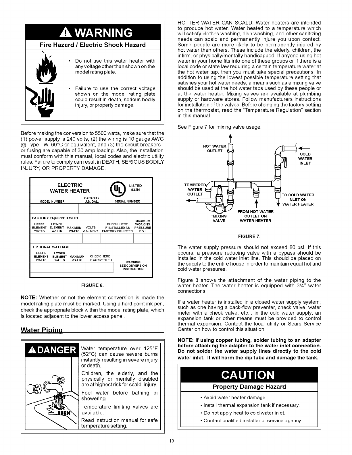
Fire Hazard /Electric Shock Hazard
Do not use this water heater with
any voltage other than shown on the
model rating plate.
Failure to use the correct voltage
shown on the model rating plate
could result in death, serious bodily
injury, or property damage.
Before making the conversion to 5500 watts, make sure that the
(1) power supply is 240 volts, (2) the wiring is 10 gauge AWG
@ Type TW, 60°C or equivalent, and (3) the circuit breakers
or fusing are capable of 30 amp loading. Also, the installation
must conform with this manual, local codes and electric utility
rules. Failure to comply can result in DEATH, SERIOUS BODILY
INJURY, OR PROPERTY DAMAGE.
ELECTRIC @LISTED
WATER HEATER 932N
CAPACITY
MODEL NUMBER U.S. GAL. SERIAL NUMBER
FACTORY EQUIPPED WITH MAXIMUM
UPPER LOWER CHECK HERE WORKING
ELEMENT ELEMENT MAXIMUM VOLTS IF INSTALLED AS PRESSURE
WATTS WATTS WATTS A.C. ONLY FACTORY EQUIPPED P.S.L
OPTIONAL WATTAGE
UPPER LOWER
ELEMENT ELEMENT MAXIMUM CHECK HERE
WATTS WATTS WATTS IF CONVERTED WARNING
SEE CONVERSION
INSTRUCTION
FIGURE 6.
NOTE: Whether or not the element conversion is made the
model rating plate must be marked. Using a hard point ink pen,
check the appropriate block within the model rating plate, which
is located adjacent to the lower access panel.
Water PiDino
IK!Wm7:t ::1:II Water temperature over 125°F
(52°C) can cause severe burns
instantly resulting in severe injury
or death.
Children, the elderly, and the
physically or mentally disabled
are at highest riskfor scald injury.
Feel water before bathing or
showering.
Temperature limiting valves are
available.
Read instruction manual for safe
temperature setting.
HOTTER WATER CAN SCALD: Water heaters are intended
to produce hot water. Water heated to a temperature which
wilt satisfy clothes washing, dish washing, and other sanitizing
needs can scald and permanently injure you upon contact.
Some people are more likely to be permanently injured by
hot water than others. These include the elderly, children, the
infirm, or physically/mentally handicapped. If anyone using hot
water in your home fits into one of these groups or ifthere is a
local code or state taw requiring a certain temperature water at
the hot water tap, then you must take special precautions. In
addition to using the lowest possible temperature setting that
satisfies your hot water needs, a means such as a mixing valve
should be used at the hot water taps used by these people or
at the water heater. Mixing valves are available at plumbing
supply or hardware stores. Follow manufacturers instructions
for installation of the valves. Before changing the factory setting
on the thermostat, read the "Temperature Regulation" section
in this manual.
See Figure 7 for mixing valve usage.
f
HOTWATERFI
OUTLET COLD
LJ I'_ WATER
WATER_ I-_ LL_- -_ !_
OUTL_ _ I_ l-1TO COLD WATER
<[_)'_E)I _1 •_INLET ON
T • WATERHEATER
FROM HOT WATER
*MIXING OUTLET ON
VALVE WATER HEATER
FIGURE 7.
The water supply pressure should not exceed 80 psi. If this
occurs, a pressure reducing valve with a bypass should be
installed in the cold water inlet line. This should be placed on
the supply to the entire house in order to maintain equal hot and
cold water pressures.
Figure 8 shows the attachment of the water piping to the
water heater. The water heater is equipped with 3/4" water
connections.
If a water heater is installed in a closed water supply system;
such as one having a back-flow preventer, check valve, water
meter with a check valve, etc.., in the cold water supply; an
expansion tank or other means must be provided to control
thermal expansion. Contact the local utility or Sears Service
Center on how to control this situation.
NOTE: If using copper tubing, solder tubing to an adapter
before attaching the adapter to the water inlet connection.
Do not solder the water supply lines directly to the cold
water inlet. It will harm the dip tube and damage the tank.
Property Damage Hazard
• Avoid water heater damage.
• Install thermal expansion tank if necessary.
• Do not apply heat to cold water inlet.
• Contact qualified installer or service agency.
10
NOTE: To protect against untimely corrosion of hot and cold
water fittings, it is strongly recommended that di-electric
unions or couplings be installed on this water heater when
connected to copper pipe.
1. Look at the top cover of the water heater. The hot water
outlet is marked hot. Put two or three turns of teflon tape
around the threaded end of the threaded-to-sweat coupling
and around both ends of the 3/4" threaded nipple. Using
flexible connectors, connect the hot water pipe to the hot
water outlet of the water heater.
2. Look at the top cover of the water heater. The cold water inlet
is marked cold. Put two or three turns of teflon tape around
the threaded end of the threaded-to-sweat coupling and
around both ends of the 3/4" threaded nipple. Using flexible
connectors, connect the cold water pipe to the cold water inlet
of the water heater.
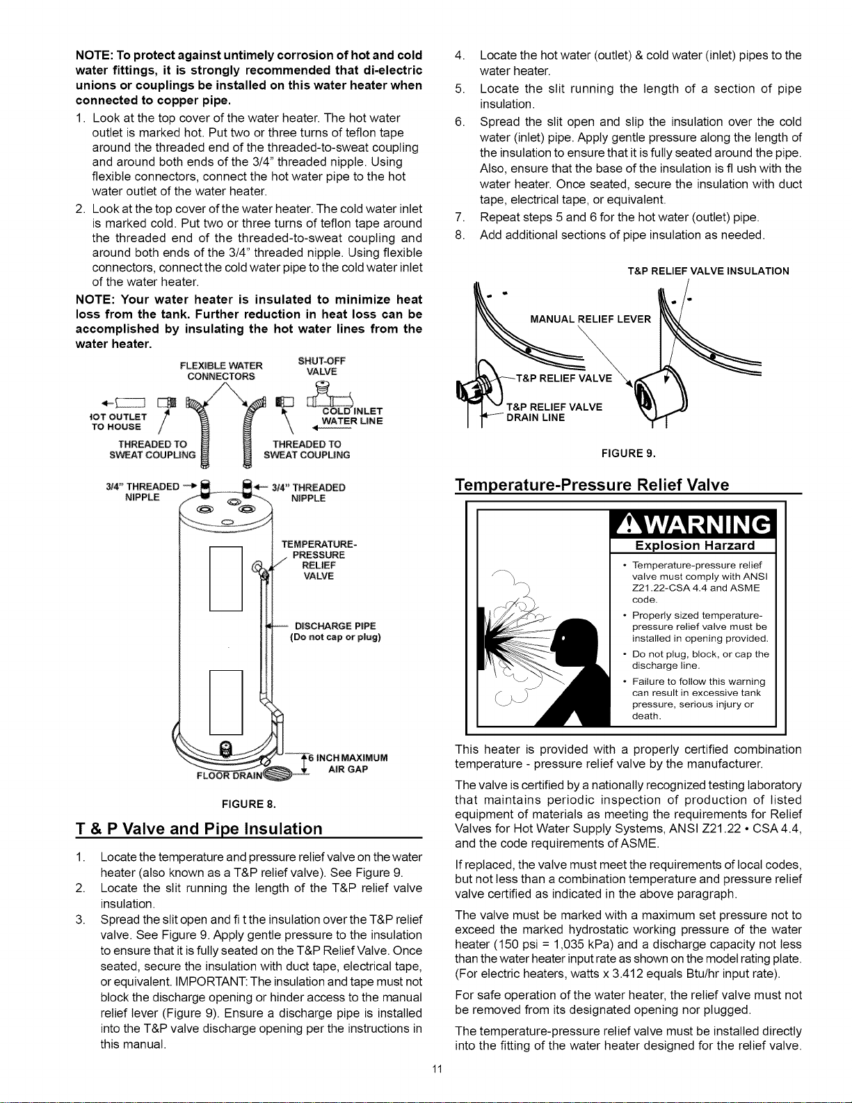
NOTE: Your water heater is insulated to minimize heat
loss from the tank. Further reduction in heat loss can be
accomplished by insulating the hot water lines from the
water heater.
FLEXIBLE WATER SHUT43FF
CONNECTORS VALVE
tOT 0LIT_T f _ _ ", WATER LiNE
TO HOUSE // _ _ \
THREADED TO _ _ THREADED TO
SWEAT COUPU WEAT COUPLING
3/4" THREADED
N|PPLE
4. Locate the hot water (outlet) & cold water (inlet) pipes to the
water heater.
5. Locate the slit running the length of a section of pipe
insulation.
6. Spread the slit open and slip the insulation over the cold
water (inlet) pipe. Apply gentle pressure along the length of
the insulation to ensure that it is fully seated around the pipe.
Also, ensure that the base of the insulation is flush with the
water heater. Once seated, secure the insulation with duct
tape, electrical tape, or equivalent.
7. Repeat steps 5 and 6 for the hot water (outlet) pipe.
8. Add additional sections of pipe insulation as needed.
T&P RELIEF VALVE INSULATION
MANUAL RELIEF LEVER
RELIEF_
RELIEF VALVE
FIGURE 9.
Temperature-Pressure Relief Valve
FLOOR DRA|N
TEMPEP_ATURE=
PRESSURE
// RELIEF
VALVE
-- D|SCHARGE PIPE
(Don_ capocp|ug)
FIGURE 8.
T& P Valve and Pipe Insulation
1.
2.
3.
Locate the temperature and pressure relief valve on the water
heater (also known as a T&P relief valve). See Figure 9.
Locate the slit running the length of the T&P relief valve
insulation.
Spread the slit open and fi t the insulationover the T&P relief
valve. See Figure 9. Apply gentle pressure to the insulation
to ensure that itisfully seated on the T&P Relief Valve. Once
seated, secure the insulationwith duct tape, electrical tape,
or equivalent. IMPORTANT: The insulationand tape must not
block the discharge opening or hinder access to the manual
relief lever (Figure 9). Ensure a discharge pipe is installed
into the T&P valve discharge opening per the instructions in
this manual.
Explosion Harzard
• Temperature-pressure relief
valve must comply with ANSI
Z21.22-CSA 4.4 and ASME
code.
• Properly sized temperature-
pressure relief valve must be
installed in opening provided.
• Do not plug, block, or cap the
discharge line.
• Failure to follow this warning
can result in excessive tank
pressure, serious injury or
death.
11
This heater is provided with a properly certified combination
temperature - pressure relief valve by the manufacturer.
The valve is certified by a nationally recognized testing laboratory
that maintains periodic inspection of production of listed
equipment of materials as meeting the requirements for Relief
Valves for Hot Water Supply Systems, ANSI Z21.22 •CSA 4.4,
and the code requirements of ASME.
If replaced, the valve must meet the requirements of local codes,
but not less than a combination temperature and pressure relief
valve certified as indicated in the above paragraph.
The valve must be marked with a maximum set pressure not to
exceed the marked hydrostatic working pressure of the water
heater (150 psi = 1,035 kPa) and a discharge capacity not tess
than the water heater input rate as shown on the model rating plate.
(For electric heaters, watts x 3.412 equals Btu/hr input rate).
For safe operation of the water heater, the relief valve must not
be removed from its designated opening nor plugged.
The temperature-pressure relief valve must be installed directly
into the fitting of the water heater designed for the relief valve.
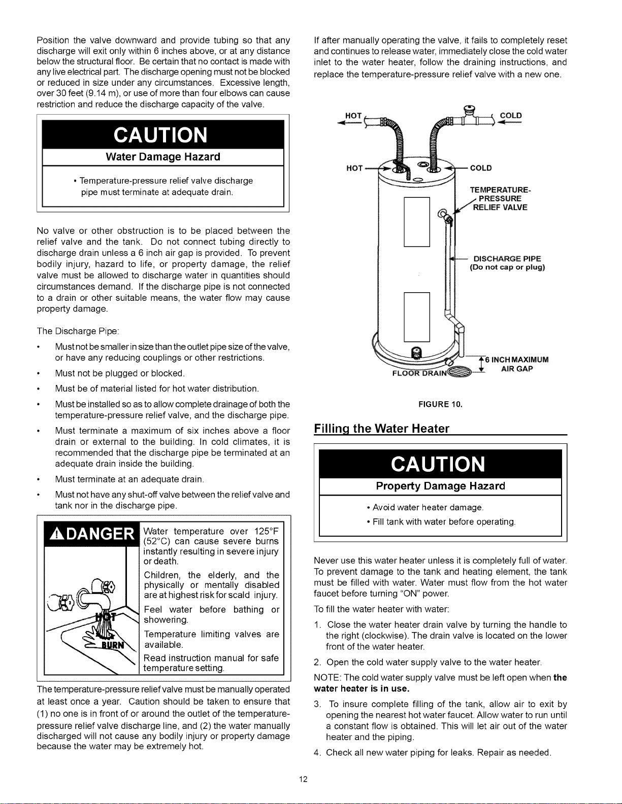
Positionthevalvedownwardandprovidetubingsothatany
dischargewiltexitonlywithin6inchesabove,oratanydistance
belowthestructuralfloor.Becertainthatnocontactismadewith
anyliveelectricalpart.Thedischargeopeningmustnotbeblocked
orreducedinsizeunderanycircumstances.Excessivelength,
over30feet(9.14m),oruseofmorethanfourelbowscancause
restrictionandreducethedischargecapacityofthevalve.
Water Damage Hazard
• Temperature-pressure relief valve discharge
pipe must terminate at adequate drain.
No valve or other obstruction is to be placed between the
relief valve and the tank. Do not connect tubing directly to
discharge drain unless a 6 inch air gap is provided. To prevent
bodily injury, hazard to life, or property damage, the relief
valve must be allowed to discharge water in quantities should
circumstances demand. Ifthe discharge pipe is not connected
to a drain or other suitable means, the water flow may cause
property damage.
The Discharge Pipe:
• Must not besmaller in size than the outlet pipe size of the valve,
or have any reducing couplings or other restrictions.
• Must not be plugged or blocked.
• Must be of material listed for hot water distribution.
• Must be installed so as to altow complete drainage of both the
temperature-pressure relief valve, and the discharge pipe.
• Must terminate a maximum of six inches above a floor
drain or external to the building. In cold climates, it is
recommended that the discharge pipe be terminated at an
adequate drain inside the building.
• Must terminate at an adequate drain.
• Must not have any shut-off valve between the relief valve and
tank nor in the discharge pipe.
Water temperature over 125°F
(52°C) can cause severe burns
instantly resulting in severe injury
or death.
Children, the elderly, and the
i_ physically or mentally disabled
are at highest riskfor scald injury.
_,,_, Feel water before bathing or
_ _ showering
r Temperature limiting valves are
available.
Read instruction manual for safe
,. temperature setting.
The temperatureipressure relief valve must be manually operated
at least once a year. Caution should be taken to ensure that
(1) no one is in front of or around the outlet of the temperature-
pressure relief valve discharge line, and (2) the water manually
discharged wilt not cause any bodily injury or property damage
because the water may be extremely hot.
If after manually operating the valve, it fails to completely reset
and continues to release water, immediately close the cold water
inlet to the water heater, follow the draining instructions, and
replace the temperature-pressure relief valve with a new one.
.oTi _C°LD
_MPERATURE-
PRESSURE
DISCHARGE PIPE
(Do not cap or plug)
INCH MAXIMUM
AIR GAP
FIGURE 10.
Filling the Water Heater
Property Damage Hazard
• Avoid water heater damage.
•Filltank with water before operating.
Never use this water heater unless it is completely full of water.
To prevent damage to the tank and heating element, the tank
must be filled with water. Water must flow from the hot water
faucet before turning "ON" power.
To fill the water heater with water:
1. Close the water heater drain valve by turning the handle to
the right (clockwise). The drain valve is located on the lower
front of the water heater.
2. Open the cold water supply valve to the water heater.
NOTE: The cold water supply valve must be left open when the
water heater is in use.
3. To insure complete filling of the tank, allow air to exit by
opening the nearest hot water faucet. Allow water to run until
a constant flow is obtained. This will let air out of the water
heater and the piping.
4. Check all new water piping for leaks. Repair as needed.
12
Converting the Lower Element
These instructions only cover the conversion of the convertible
element, read this entire manual before attempting to install
or operate the water heater. The water heater is factory set to
operate at 3800 watts. The lower element can be converted to
operate at 5500 watts. Refer to "Facts to Consider About the
Convertible Lower Element" section.
The Upper Element, (if double element model)is a conventional
3800 watt element which only operates at its rated wattage on
240 volts. (See rating plate on the water heater.
The lower Element of the water heater can be converted from
operation at 3800 watts to 5500 watts on a 240 volt system.
If after reading these instructions and this manual, if you do not
understand any portion call Sears Service Center.
Fire Hazard /Electric Shock Hazard
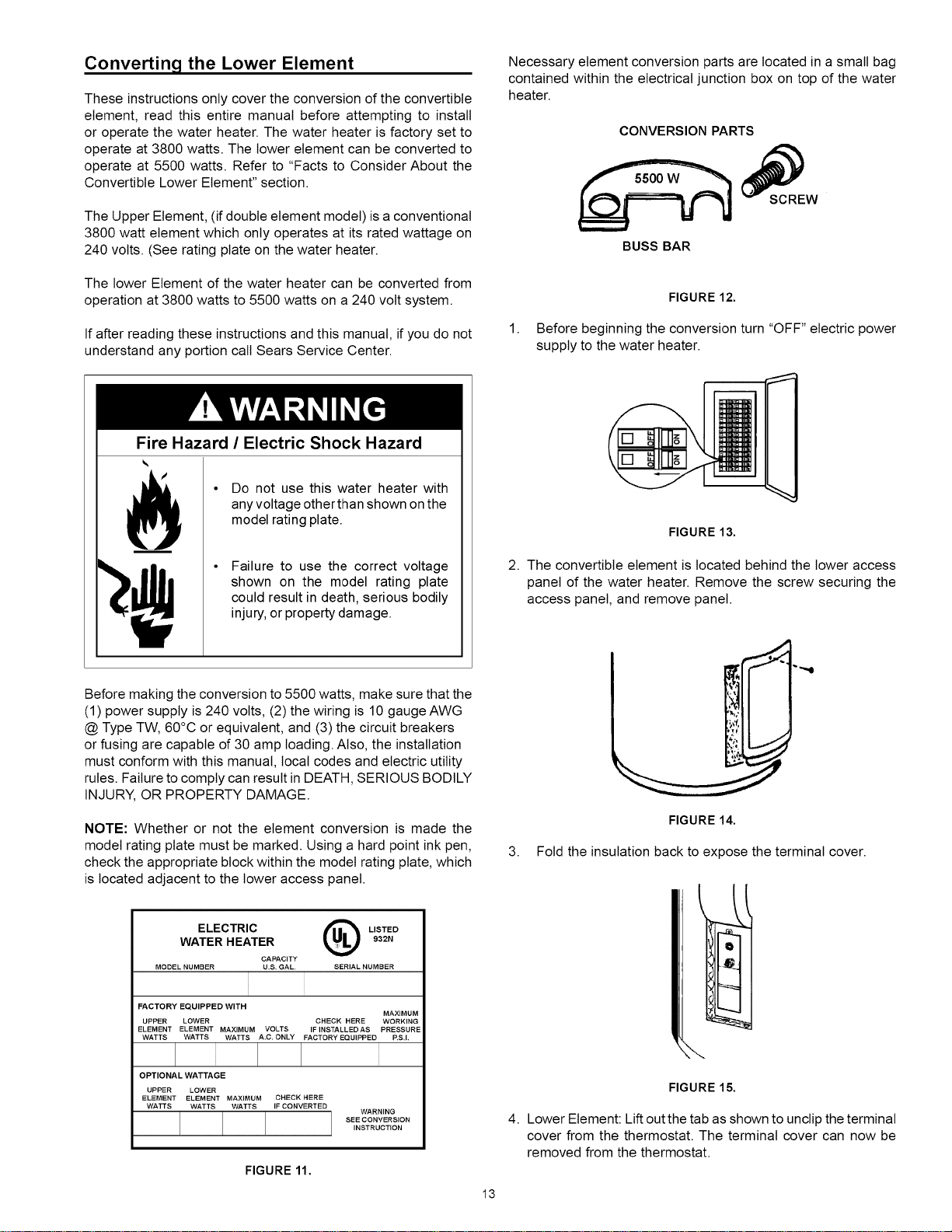
Necessary element conversion parts are located in a small bag
contained within the electrical junction box on top of the water
heater.
CONVERSION PARTS
BUSS BAR
1.
FIGURE 12.
Before beginning the conversion turn "OFF" electric power
supply to the water heater.
• Do not use this water heater with
any voltage other than shown on the
model rating plate.
Failure to use the correct voltage
shown on the model rating plate
could result in death, serious bodily
injury, or property damage.
Before making the conversion to 5500 watts, make sure that the
(1) power supply is 240 volts, (2) the wiring is 10 gauge AWG
@ Type TW, 60°C or equivalent, and (3) the circuit breakers
or fusing are capable of 30 amp loading. Also, the installation
must conform with this manual, local codes and electric utility
rules. Failure to comply can result in DEATH, SERIOUS BODILY
INJURY, OR PROPERTY DAMAGE.
NOTE: Whether or not the element conversion is made the
model rating plate must be marked. Using a hard point ink pen,
check the appropriate block within the model rating plate, which
is located adjacent to the lower access panel.
ELECTRIC @LISTED
WATER HEATER 932N
CAPACITY
MODEL NUMBER U,B. GAL, SERIAL NUMBER
FACTORY EQUIPPED WITH MAXIMUM
UPPER LOWER CHECK HERE WORKING
ELEMENT ELEMENT MAXIMUM VOLTS IFINSTALLEDAS PRESSURE
WATTS WATTS WATTS A.C. ONLY FACTORY EQUIPPED P,S,I.
OPTIONAL WATTAGE
UPPER LOWER
ELEMENT ELEMENT MAXIMUM CHECK HERE
WATTS WATTS WATTS IF CONVERTED WARNING
SEE CONVERSION
INSTRUCTION
FIGURE 11.
13
FIGURE 13.
2. The convertible element is located behind the lower access
panel of the water heater. Remove the screw securing the
access panel, and remove panel.
FIGURE 14.
3. Fold the insulation back to expose the terminal cover.
--...
FIGURE 15.
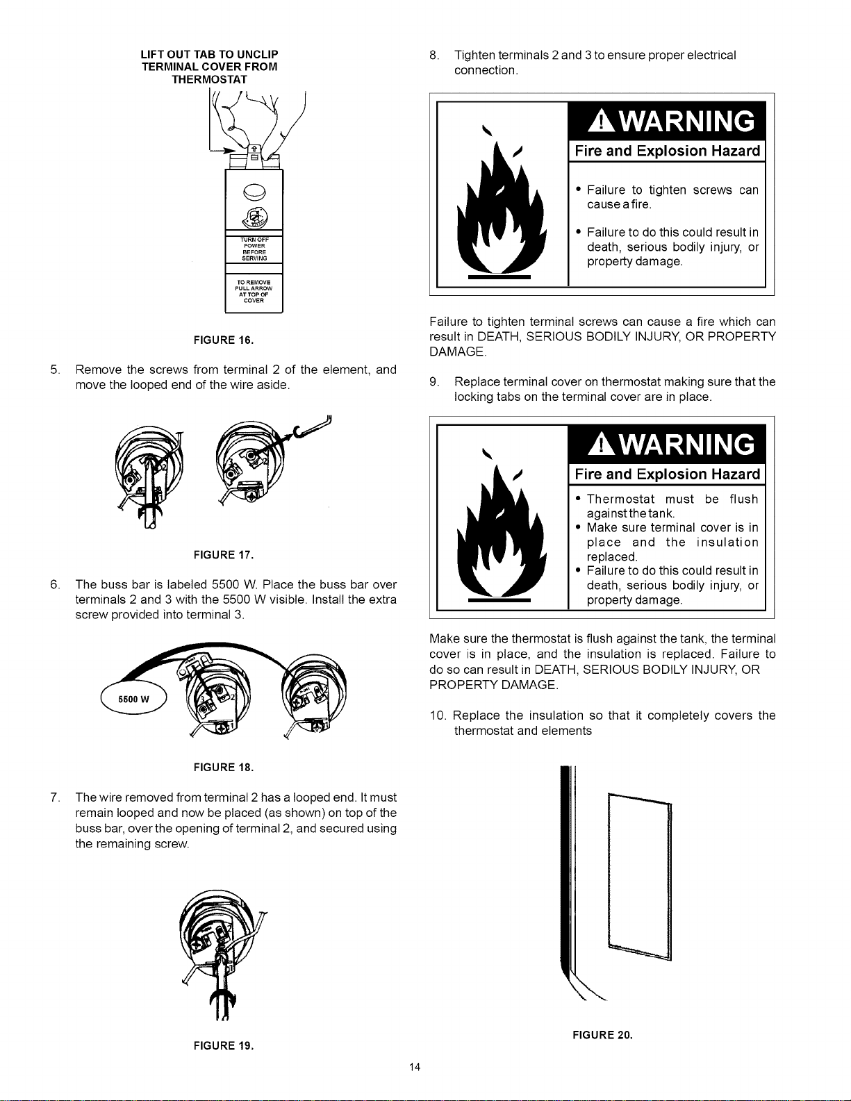
4. Lower Element: Lift out the tab as shown to unclip the terminal
cover from the thermostat. The terminal cover can now be
removed from the thermostat.
5.
6.
LIFT OUT TAB TO UNCLIP
TERMINAL COVER FROM
THERMOSTAT
FIGURE 16.
Remove the screws from terminal 2 of the element, and
move the looped end of the wire aside.
FIGURE 17.
The buss bar is labeled 5500 W. Place the buss bar over
terminals 2 and 3 with the 5500 W visible. Install the extra
screw provided into terminal 3.
8. Tighten terminals 2 and 3 to ensure proper electrical
connection.
Fire and Explosion Hazard
" Failure to tighten screws can
cause afire.
,, Failure to do this could result in
death, serious bodily injury, or
property damage.
Failure to tighten terminal screws can cause a fire which can
result in DEATH, SERIOUS BODILY INJURY, OR PROPERTY
DAMAGE.
9. Replace terminal cover on thermostat making sure that the
locking tabs on the terminal cover are in place.
must be flush
against the tank.
Make sure t min :ov "is in
place and the insulation
replaced.
" Thermostat
,, Make sure terminal cover is in
,, Failure to do this could result in
death, serious bodily injury, or
property damage.
Fire and Explosion Hazard
Make sure the thermostat is flush against the tank, the terminal
cover is in place, and the insulation is replaced. Failure to
do so can result in DEATH, SERIOUS BODILY INJURY, OR
PROPERTY DAMAGE.
10. Replace the insulation so that it completely covers the
thermostat and elements
7.
FIGURE 18.
The wire removed from terminal 2 has a looped end. It must
remain looped and now be placed (as shown) on top of the
buss bar, over the opening of terminal 2, and secured using
the remaining screw.
FIGURE 19.
14
FIGURE 20.
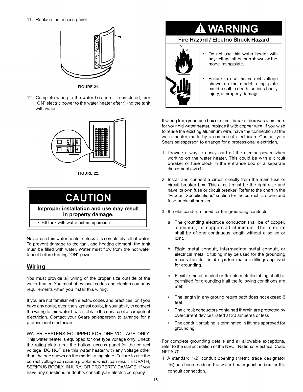
11. Replace the access panel.
_ d" ""Q
FIGURE 21.
12. Complete wiring to the water heater, or if completed, turn
"ON" electric power to the water heater after filling the tank
with water.
Fire Hazard /Electric Shock Hazard
• Do not use this water heater with
any voltage other than shown on the
model rating plate.
Failure to use the correct voltage
shown on the model rating plate
could result in death, serious bodily
injury, or property damage.
FIGURE 22.
Improper installation and use may result
in property damage.
• Fill tank with water before operation.
Never use this water heater unless it is completely full of water.
To prevent damage to the tank and heating element, the tank
must be filled with water. Water must flow from the hot water
faucet before turning "ON" power.
Wiring
You must provide all wiring of the proper size outside of the
water heater. You must obey local codes and electric company
requirements when you install this wiring.
If you are not familiar with electric codes and practices, or if you
have any doubt, even the slightest doubt, in your ability to connect
the wiring to this water heater, obtain the service of a competent
electrician. Contact your Sears salesperson to arrange for a
professional electrician.
WATER HEATERS EQUIPPED FOR ONE VOLTAGE ONLY:
This water heater is equipped for one type voltage only. Check
the rating plate near the bottom access panel for the correct
voltage. DO NOT use this water heater with any voltage other
than the one shown on the model rating plate. Failure to use the
correct voltage can cause problems which can result in DEATH,
SERIOUS BODILY INJURY, OR PROPERTY DAMAGE. Ifyou
have any questions or doubts consult your electric company.
Ifwiring from your fuse box or circuit breaker box was aluminum
for your old water heater, replace it with copper wire. Ifyou wish
to reuse the existing aluminum wire, have the connection at the
water heater made by a competent electrician. Contact your
Sears salesperson to arrange for a professional electrician.
1. Provide a way to easily shut off the electric power when
working on the water heater. This could be with a circuit
breaker or fuse block in the entrance box or a separate
disconnect switch.
2. Install and connect a circuit directly from the main fuse or
circuit breaker box. This circuit must be the right size and
have its own fuse or circuit breaker. Refer to the chart in the
"Product Specifications" section for the correct size wire and
fuse or circuit breaker.
3. If metal conduit is used for the grounding conductor:
a. The grounding electrode conductor shall be of copper,
aluminum, or copperctad aluminum. The material
shall be of one continuous length without a splice or
joint.
b. Rigid metal conduit, intermediate metal conduit, or
electrical metallic tubing may be used for the grounding
means if conduit or tubing is terminated infittings approved
for grounding.
c. Flexible metal conduit or flexible metallic tubing shall be
permitted for grounding if all the following conditions are
met:
The length in any ground return path does not exceed 6
feet.
• The circuit conductors contained therein are protected by
overcurrent devices rated at 20 amperes or less.
• The conduit or tubing is terminated in fittings approved for
grounding.
For complete grounding details and all allowable exceptions,
refer to the current edition of the NEC- National Electrical Code
NFPA 70.
4. A standard 112" conduit opening (metric trade designator
16) has been made in the water heater junction box for the
conduit connection.
15
5. Awiring diagram (Figure 24) has been provided to show the
connections between the water heater and the power supply.
Two Wire Connection Diagrams: is the most common
requiring you to simply connect red to red, black to black,
and the ground wire to the green ground screw in the
junction box of the water heater.
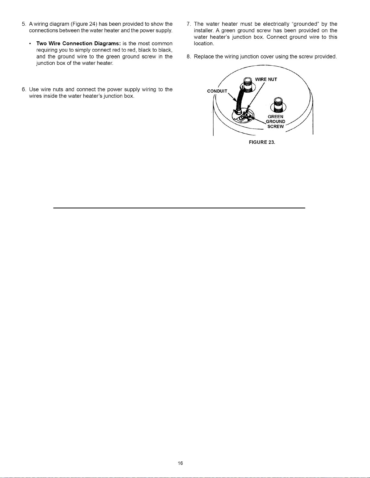
7. The water heater must be electrically "grounded" by the
installer. A green ground screw has been provided on the
water heater's junction box. Connect ground wire to this
location.
8. Replace the wiring junction cover using the screw provided.
6. Use wire nuts and connect the power supply wiring to the
wires inside the water heater's junction box. CONDUIT
GREEN
.GROUND
SCREW
FIGURE 23.
16
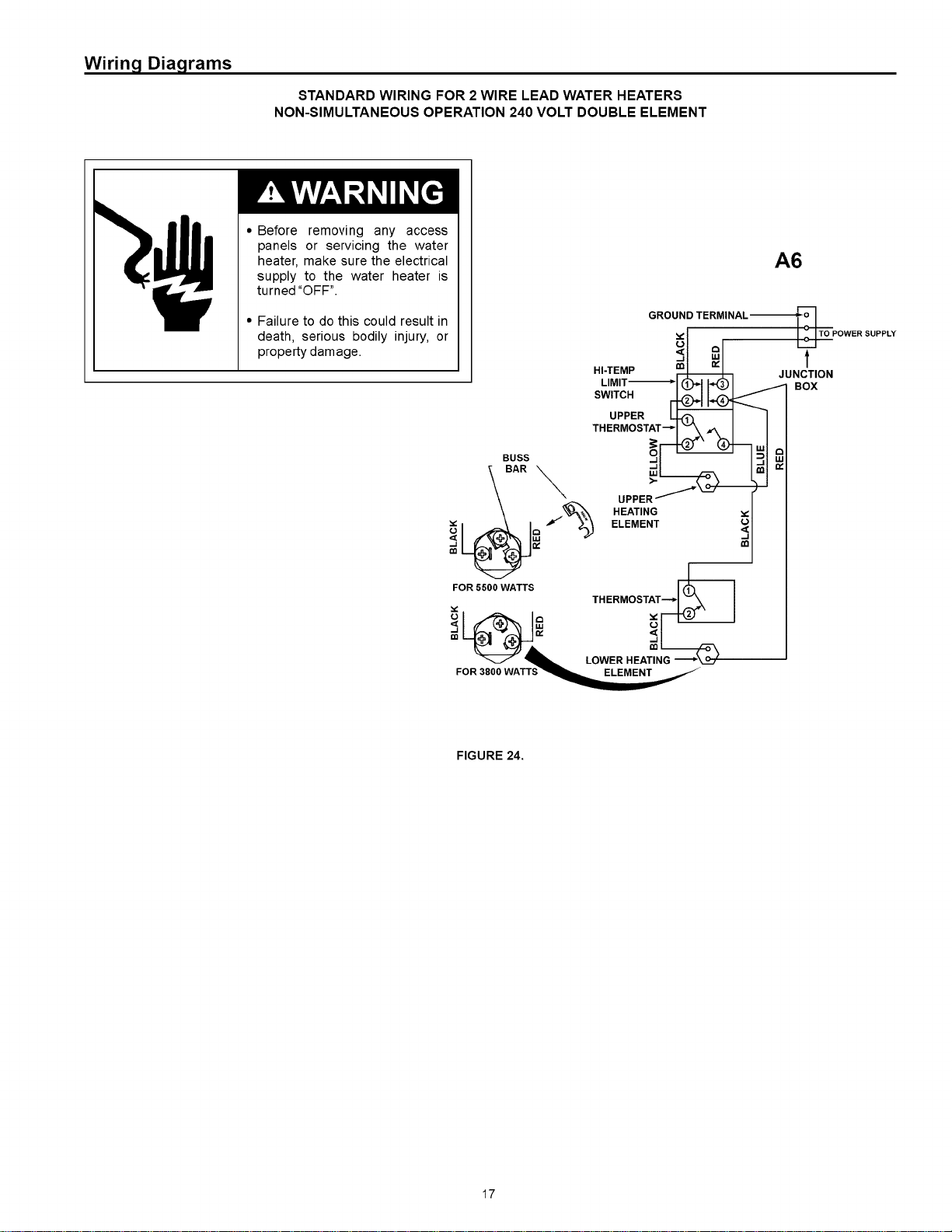
Wiring Diagrams
STANDARD WIRING FOR 2 WIRE LEAD WATER HEATERS
NON-SIMULTANEOUS OPERATION 240 VOLT DOUBLE ELEMENT
• Before removing any access
panels or servicing the water
heater, make sure the electrical
supply to the water heater is
turned "OFF".
• Failure to do this could result in
death, serious bodily injury, or
property damage.
A6
GROUND TERMINAL-I_._
_, I_TO POWER SUPPLY
Ul _1 L.C..I
_,1 ,,=,1 t
HI-TEMP _JUNCTION
LIMIT-I*I (D_II*QI _ BOX
SWITCH r44_ _
OPPER
THERMOSTAT__ _lm
UppE:11._(_ )I
HEATING
fELEMENT m
FIGURE 24.
17
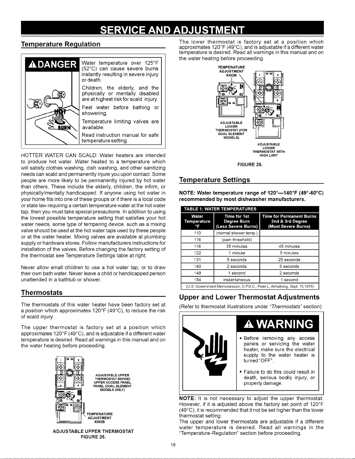
Temperature Regulation
r!ll m7,_I[e] r,t Water temperature over 125°F
(52°C) can cause severe burns
instantly resulting in severe injury
or death.
Children, the elderly, and the
_,__ hysically or mentally disabled
are at highest risk for scald injury.
Feel water before bathing or
/__ showering.
Temperature limiting valves are
available.
Read instruction manual for safe
-, temperature setting.
HOTTER WATER CAN SCALD: Water heaters are intended
to produce hot water. Water heated to a temperature which
wilt satisfy clothes washing, dish washing, and other sanitizing
needs can scald and permanently injure you upon contact. Some
people are more likely to be permanently injured by hot water
than others. These include the elderly, children, the infirm, or
physically/mentally handicapped. If anyone using hot water in
your home fits into one of these groups or if there is a local code
or state law requiring a certain temperature water at the hot water
tap, then you must take special precautions. In addition to using
the lowest possible temperature setting that satisfies your hot
water needs, some type of tempering device, such as a mixing
valve should be used at the hot water taps used by these people
or at the water heater. Mixing valves are available at plumbing
supply or hardware stores. Follow manufacturers instructions for
installation of the valves, Before changing the factory setting of
the thermostat see Temperature Settings table at right.
Never allow small children to use a hot water tap, or to draw
their own bath water. Never leave achild or handicapped person
unattended in a bathtub or shower.
Thermostats
The thermostats of this water heater have been factory set at
a position which approximates 120°F (49°C), to reduce the risk
of scald injury.
The upper thermostat is factory set at a position which
approximates 120°F (49°C), and is adjustable if a different water
temperature is desired. Read all warnings in this manual and on
the water heating before proceeding.
_i ADJUSTABLE UPPER
THERMOSTAT BEHIND
UPPER ACCESS PANEL
PANEL (DUAL ELEMENT
ADJUSTABLE UPPER THERMOSTAT
FIGURE 25.
The lower thermostat is factory set at a position which
approximates 120°F (49°C), and is adjustable if a different water
temperature isdesired. Read all warnings in this manual and on
the water heating before proceeding.
TEMPERATURE
ADJUSTMENT
KNOB
ADJUSTABLE
LOWER
THERMOSTAT (FOR
DUAL ELEMENT
MODELS)
ADJUSTABLE
LOWER
THERMOSTAT WITH
HIGH LIMIT
FIGURE 26.
Temperature Settings
NOTE: Water temperature range of 120°m140°F (49°-60°C)
recommended by most dishwasher manufacturers.
110 (normal shower temp.)
116 (pain threshold)
116 35 minutes 45 minutes
122 1 minute 5 minutes
131 5 seconds 25 seconds
140 2 seconds 5 seconds
149 1 second 2 seconds
154 instantaneous 1 second
(U.S. Government Memorandum, C.RS.C., Peter L.Armstrong, Sept. 15,1978)
Upper and Lower Thermostat Adjustments
Refer to thermostat illustrations under "Thermostats" section)
• Before removing any access
panels or servicing the water
heater, make sure the electrical
supply to the water heater is
turned "OFF".
• Failure to do this could result in
death, serious bodily injury, or
property damage.
NOTE: It is not necessary to adjust the upper thermostat.
However, if it is adjusted above the factory set point of 120°F
(49°C), it is recommended that it not be set higher than the lower
thermostat setting.
The upper and lower thermostats are adjustable if a different
water temperature is desired. Read all warnings in the
"Temperature-Regulation" section before proceeding.
18
1. Turn "OFF" the electric power to the water heater at the
junction box.
• Before removing any access
panels or servicing the water
heater, make sure the electrical
supply to the water heater is
turned "OFF".
• Failure to do this could result in
death, serious bodily injury, or
property damage.
2. Take off the upper and/or lower access panel(s), then fold the
insulation back to expose the thermostat.
3. The slotted adjustment (using a screwdriver) can be turned
clockwise (t_ ) to increase the temperature setting or counter
clockwise ( _'_ ) to decrease the temperature setting.
4. Replace the insulation and access panel.
5. Turn "ON" the power supply.
Anode Rod Inspection
Property Damage Hazard
•Avoid water heater damage.
• Inspection and replacement of anode as needed.
Each water heater contains at least one anode rod, which will
slowly deplete (due to electrolysis) prolonging the life of the
water heater by protecting the glass-lined tank from corrosion.
Adverse water quality, hotter water temperatures, high hot
water usage, hydronic heating devices, and water softening
methods can increase the rate of anode rod depletion. Once
the anode rod is depleted, the tank will start to corrode, even-
tually developing a leak.
Certain water conditions wilt cause a reaction between the
anode rod and the water. The most common complaint associ-
ated with the anode rod is a "rotten egg smell" produced from
the presence of hydrogen sulfide gas dissolved in the water.
IMPORTANT: Do not remove this anode rod permanently as it
wilt void any warranties. A special anode rod may be available
if water odor or discoloration occurs.
NOTE: This anode rod may reduce but not eliminate water
odor problems. The water supply system may require special
filtration equipment from a water conditioning company to suc-
cessfully eliminate all water odor problems.
Artificially softened water is exceedingly corrosive because the
process substitutes sodium ions for magnesium and calcium
ions.
The anode rod should be inspected after a maximum of three
years and annually thereafter until the condition of the anode
rod dictates its replacement. NOTE: Artificially softened water
requires the anode rod to be inspected annually.
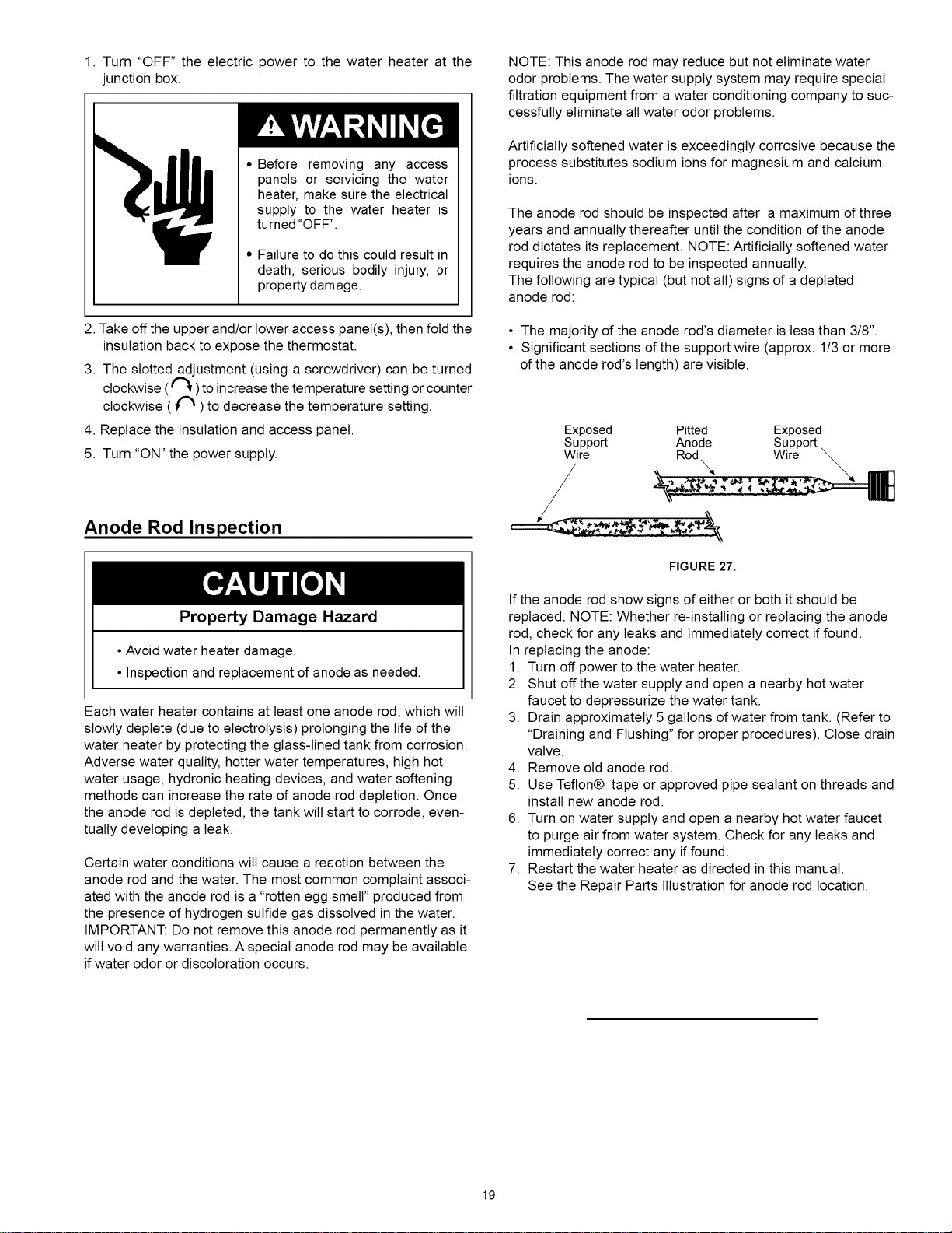
The following are typical (but not all) signs of a depleted
anode rod:
• The majority of the anode rod's diameter is less than 3/8".
• Significant sections of the support wire (approx. 1/3 or more
of the anode rod's length) are visible.
Exposed Pitted
Support Anode
Wire Rod
Exposed
Suppo_
Wire
FIGURE 27.
If the anode rod show signs of either or both it should be
replaced. NOTE: Whether re-installing or replacing the anode
rod, check for any leaks and immediately correct if found.
In replacing the anode:
1. Turn off power to the water heater.
2. Shut off the water supply and open a nearby hot water
faucet to depressurize the water tank.
3. Drain approximately 5 gallons of water from tank. (Refer to
"Draining and Flushing" for proper procedures). Close drain
valve.
4. Remove old anode rod.
5. Use Teflon® tape or approved pipe sealant on threads and
install new anode rod.
6. Turn on water supply and open a nearby hot water faucet
to purge air from water system. Check for any leaks and
immediately correct any if found.
7. Restart the water heater as directed in this manual.
See the Repair Parts Illustration for anode rod location.
19
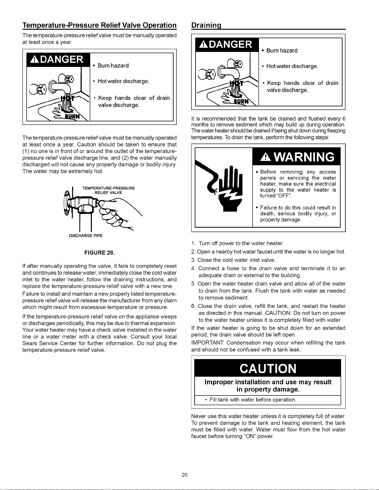
Temperature-Pressure Relief Valve Operation
The temperature-pressure relief valve must be manually operated
at least once a year.
r I,7_,I [e]q • Burn hazard
• Hotwater discharge.
Keep hands clear of drain
valve discharge.
The temperature-pressure relief valve must be manually operated
at least once a year. Caution should be taken to ensure that
(1) no one is in front of or around the outlet of the temperature-
pressure relief valve discharge line, and (2) the water manually
discharged wilt not cause any property damage or bodily injury.
The water may be extremely hot.
TEMPERATURE-PRESSURE
DISCHARGE PIPE
FIGURE 28.
If after manually operating the valve, it fails to completely reset
and continues to release water, immediately close the cold water
inlet to the water heater, follow the draining instructions, and
replace the temperature-pressure relief valve with a new one.
Failure to install and maintain a new properly listed temperature-
pressure relief valve wilt release the manufacturer from any claim
which might result from excessive temperature or pressure.
If the temperature-pressure relief valve on the appliance weeps
or discharges periodically, this may be due to thermal expansion.
Your water heater may have a check valve installed in the water
line or a water meter with a check valve. Consult your local
Sears Service Center for further information. Do not plug the
temperature-pressure relief valve.
Drainin 9
Ir 1 B7:1 [€tq ;I • Burn hazard
• Hotwater discharge.
• Keep hands clear of drain
valve discharge.
It is recommended that the tank be drained and flushed every 6
months to remove sediment which may build up during operation.
The water heatershould bedrained ifbeing shut down during freezing
temperatures. To drain the tank, perform the following steps:
• Before removing any access
panels or servicing the water
heater, make sure the electrical
supply to the water heater is
turned "OFF".
• Failure to do this could result in
death, serious bodily injury, or
property damage.
1. Turn off power to the water heater.
2. Open anearby hot water faucet until the water is no longer hot.
3. Close the cold water inlet valve.
4. Connect a hose to the drain valve and terminate it to an
adequate drain or external to the building.
5. Open the water heater drain valve and allow all of the water
to drain from the tank. Flush the tank with water as needed
to remove sediment.
6. Close the drain valve, refill the tank, and restart the heater
as directed in this manual. CAUTION: Do not turn on power
to the water heater unless it is completely filled with water.
If the water heater is going to be shut down for an extended
period, the drain valve should be left open.
IMPORTANT: Condensation may occur when refilling the tank
and should not be confused with a tank leak.
Improper installation and use may result
in property damage.
• Fill tank with water before operation.
Never use this water heater unless it is completely full of water.
To prevent damage to the tank and heating element, the tank
must be filled with water. Water must flow from the hot water
faucet before turning "ON" power.
20
Thermostat Removal/Replacement g. Replace the insulation so that it completely covers the
thermostat•
• Before removing any access
panels or servicing the water
heater, make sure the electrical
supply to the water heater is
turned "OFF".
• Failure to do this could result in
death, serious bodily injury, or
property damage.
• Turn "OFF" the electrical power to the water heater at the
junction box.
2. Remove the access panel and fold the insulation back to
expose the thermostat.
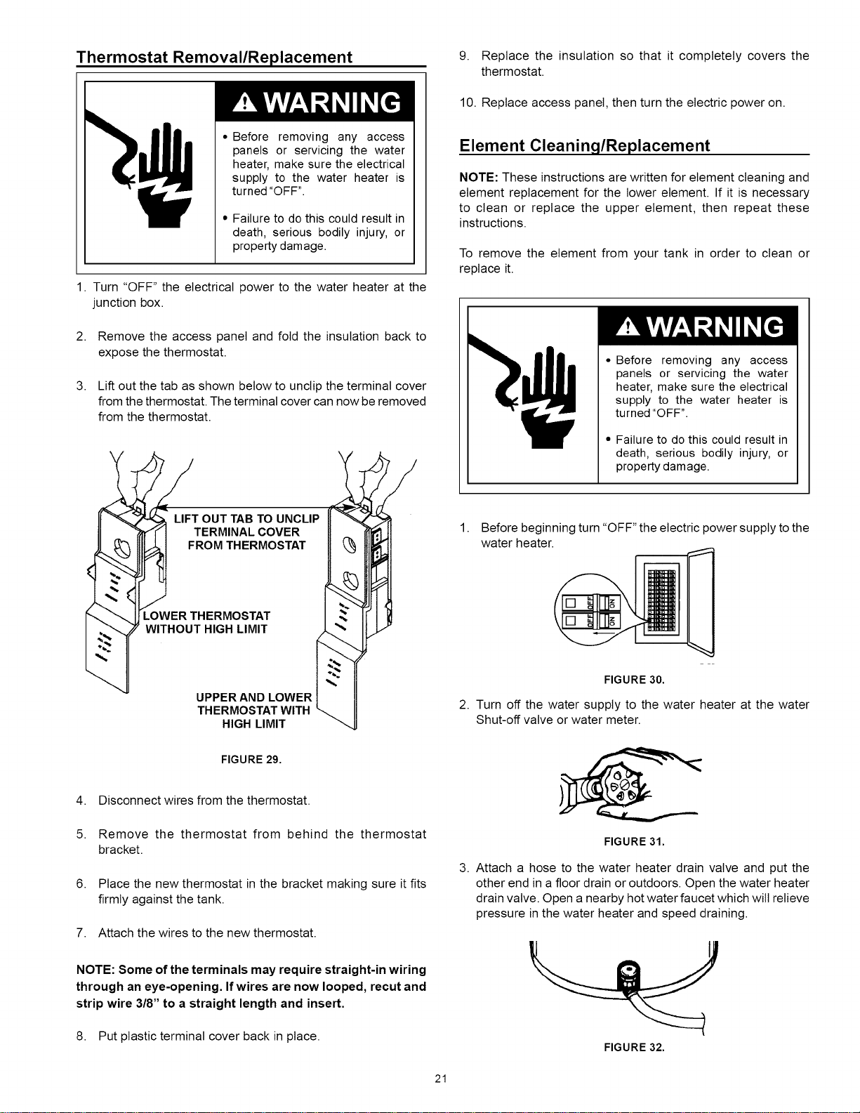
3. Lift out the tab as shown below to unctip the terminal cover
from the thermostat. The terminal cover can now be removed
from the thermostat.
EOUTTAB TO UNCLIP
ERMOSTAT
HIGH LIMIT
HIGH LIMIT
FIGURE 29.
4. Disconnect wires from the thermostat.
5. Remove the thermostat from behind the thermostat
bracket.
6. Place the new thermostat in the bracket making sure it fits
firmly against the tank.
7. Attach the wires to the new thermostat.
NOTE: Some of the terminals may require straight-in wiring
through an eye-opening. If wires are now looped, recut and
strip wire 3/8" to a straight length and insert.
8. Put plastic terminal cover back in place.
10. Replace access panel, then turn the electric power on.
Element Cleaning/Replacement
NOTE: These instructions are written for element cleaning and
element replacement for the lower element. If it is necessary
to clean or replace the upper element, then repeat these
instructions.
To remove the element from your tank in order to clean or
replace it.
• Before removing any access
panels or servicing the water
heater, make sure the electrical
supply to the water heater is
turned "OFF".
• Failure to do this could result in
death, serious bodily injury, or
property damage.
1. Before beginning turn "OFF" the electric power supply to the
water heater.
FIGURE 30.
2. Turn off the water supply to the water heater at the water
Shut-off valve or water meter.
FIGURE 31.
3. Attach a hose to the water heater drain valve and put the
other end in a floor drain or outdoors. Open the water heater
drain valve. Open a nearby hot water faucet which will relieve
pressure in the water heater and speed draining.
FIGURE 32.
21
•Burn hazard
•Hotwater discharge.
• Keep hands clear of drain
valve discharge.
The water passing out of the drain valve may be extremely hot.
To avoid being scalded, make sure all connections are tight and
that the water flow is directed away from any person.
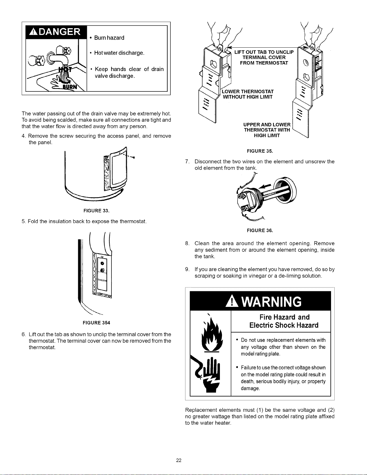
4. Remove the screw securing the access panel, and remove
the panel.
FIGURE 33.
5. Fold the insulation back to expose the thermostat.
Q
FIGURE 354
6. Lift out the tab as shown to unclip the terminal cover from the
thermostat. The terminal cover can now be removed from the
thermostat.
7.
8.
9.
OUT TAB TO UNCLIP
ERMINAL COVER
OM THERMOSTAT
HERMOSTAT
HIGH LIMIT
"__ W ITHOU'uPPER AND LOWER
THERMOSTAT WITH
HIGH LIMIT
FIGURE 35.
Disconnect the two wires on the element and unscrew the
old element from the tank.
FIGURE 36.
Clean the area around the element opening. Remove
any sediment from or around the element opening, inside
the tank.
Ifyou are cleaning the element you have removed, do so by
scraping or soaking in vinegar or a de-liming solution.
Fire Hazard and
Electric Shock Hazard
• Do not use replacement elements with
any voltage other than shown on the
model rating plate.
• Failure to usethe correct voltage shown
onthe model rating plate could result in
death, serious bodily injury, or property
damage,
Replacement elements must (1) be the same voltage and (2)
no greater wattage than listed on the model rating plate affixed
to the water heater.
22
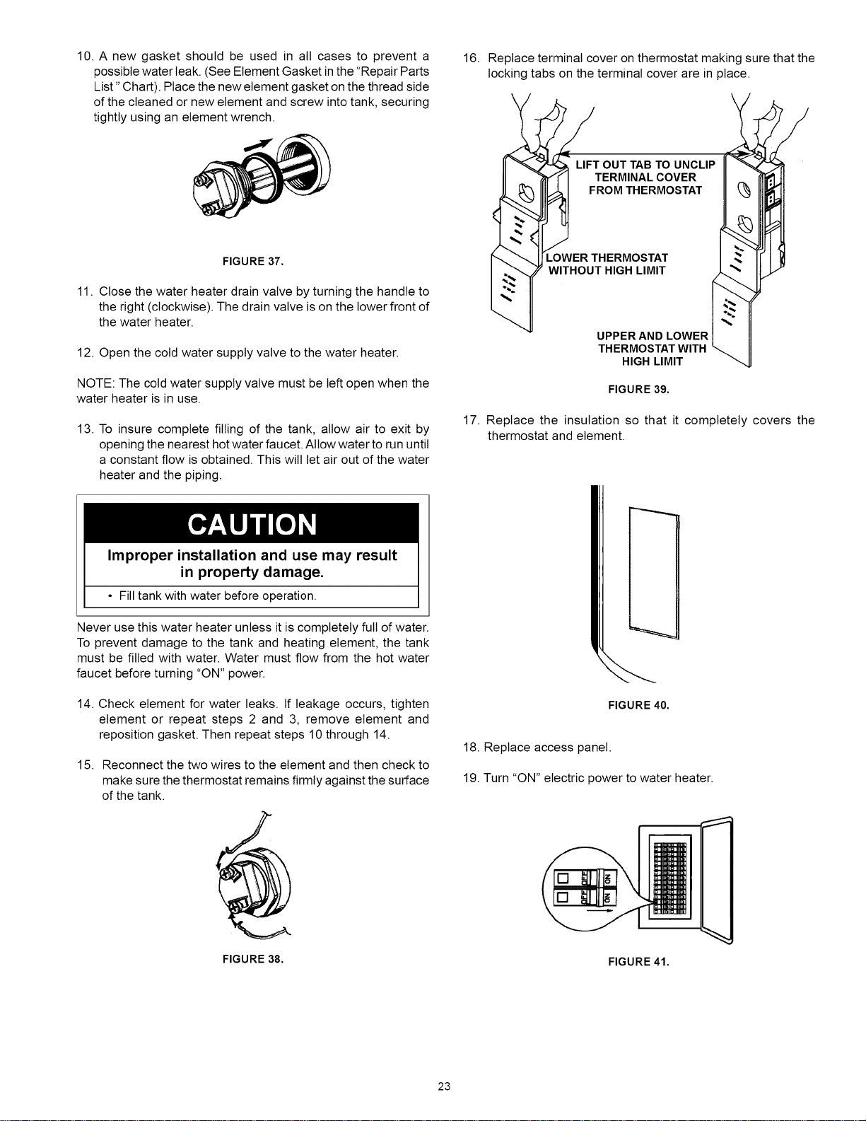
10. A new gasket should be used in all cases to prevent a
possible water leak. (See Element Gasket inthe "Repair Parts
List" Chart). Place the new element gasket on the thread side
of the cleaned or new element and screw into tank, securing
tightly using an element wrench.
FIGURE 37.
11. Close the water heater drain valve by turning the handle to
the right (clockwise). The drain valve is on the lower front of
the water heater.
12. Open the cold water supply valve to the water heater.
NOTE: The cold water supply valve must be left open when the
water heater is in use.
13. To insure complete filling of the tank, allow air to exit by
opening the nearest hot water faucet. Allow water to run until
a constant flow is obtained. This wilt let air out of the water
heater and the piping.
16. Replace terminal cover on thermostat making sure that the
locking tabs on the terminal cover are in place.
LIFT OUT TAB TO UNCLIP
TERMINAL COVER
FROM THERMOSTAT
R THERMOSTAT
UT HIGH LIMIT
_WITI- UPPERAND LOWER
THERMOSTAT WITH
HIGH LIMIT
FIGURE 39.
17. Replace the insulation so that it completely covers the
thermostat and element.
Improper installation and use may result
in property damage.
• Fill tank with water before operation.
Never use this water heater unless it is completely full of water.
To prevent damage to the tank and heating element, the tank
must be filled with water. Water must flow from the hot water
faucet before turning "ON" power.
14. Check element for water leaks. If leakage occurs, tighten
element or repeat steps 2 and 3, remove element and
reposition gasket. Then repeat steps 10 through 14.
15. Reconnect the two wires to the element and then check to
make sure the thermostat remains firmly against the surface
of the tank.
FIGURE 38.
i
FIGURE 40.
18. Replace access panel.
19. Turn "ON" electric power to water heater.
FIGURE 41.
23
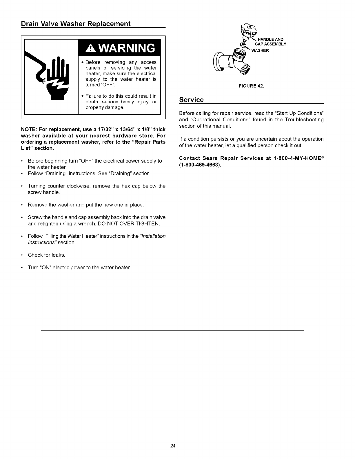
Drain Valve Washer Replacement
• Before removing any access
panels or servicing the water
heater, make sure the electrical
supply to the water heater is
turned "OFF".
• Failure to do this could result in
death, serious bodily injury, or
property damage.
NOTE: For replacement, use a 17/32" x 13/64" x 1/8" thick
washer available at your nearest hardware store. For
ordering a replacement washer, refer to the "Repair Parts
List" section.
•Before beginning turn "OFF" the electrical power supply to
the water heater.
• Follow "Draining" instructions. See "Draining" section.
• Turning counter clockwise, remove the hex cap below the
screw handle.
• Remove the washer and put the new one in place.
• Screw the handle and cap assembly back into the drain valve
and retighten using a wrench. DO NOT OVER TIGHTEN.
• Follow "Filling the Water Heater" instructionsinthe "Installation
Instructions" section.
• Check for leaks.
• Turn "ON" electric power to the water heater.
FIGURE 42.
Service
Before calling for repair service, read the "Start Up Conditions"
and "Operational Conditions" found in the Troubleshooting
section of this manual.
If a condition persists or you are uncertain about the operation
of the water heater, let a qualified person check it out.
Contact Sears Repair Services at 1-800-4-MY-HOME _
(1-800-469-4663).
24
Start Up Conditions
THERMAL EXPANSION
Property Damage Hazard
•Avoid water heater damage.
• Install thermal expansion tank or device if necessary.
• Contact qualified installer or service agency.
As water is heated, it expands (thermal expansion). In a closed
system, the volume of water will increase. As the volume of
water increases, there will be a corresponding increase in water
pressure due to thermal expansion. Thermal expansion can
cause premature tank failure (leakage). This type of failure is not
covered under the limited warranty. Thermal expansion can also
cause intermittent temperature-pressure relief valve operation:
water discharged from the valve due to excessive pressure build
up. The temperature-pressure relief valve is not intended for the
constant relief of thermal expansion. This condition is not covered
under the limited warranty.
A properly-sized thermal expansion tank should be installed
on all closed systems to control the harmful effects of thermal
expansion. Thermal expansion tanks are available from Sears
stores and through the Sears Service Centers. Contact the local
plumbing inspector, water supplier and/or the Sears Service
Center for assistance in controlling these situations.
Thermal Expansion Tank Specifications
TABLE 2.
Model
Number
153.331021
153.331051
Tank Dimensions Pipe
Capacity in Inches Fitting
In Gallons Diameter Length On Tank
2 8(203 mm) 12-3/4(323mm) 3/4" Male
5 11(279 mm) 14-3/4(375 mm) 3/4" Male
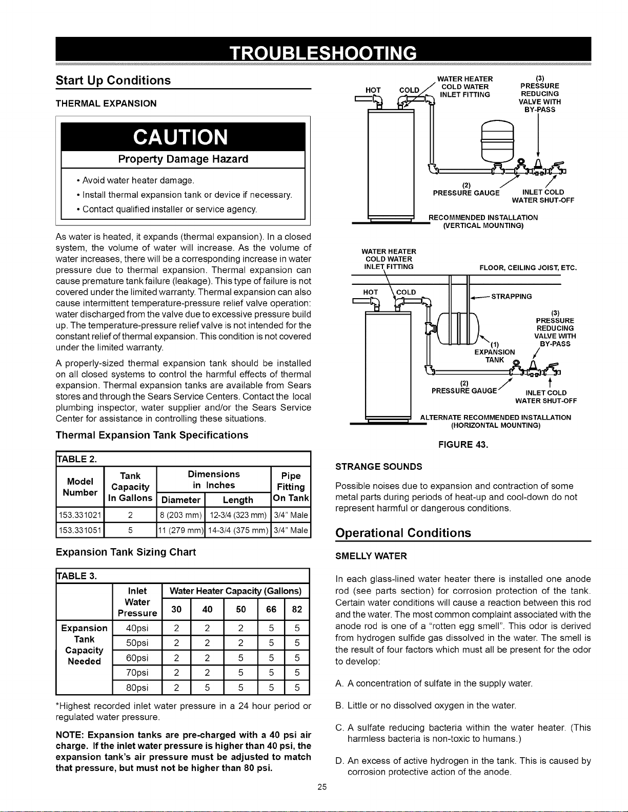
Expansion Tank Sizing Chart
WATER HEATER (3)
HOT COLD/ COLD WATER PRESSURE
r....--_-. {_- -_,._ INLET FITTING REDUCING
VALVE WITH
BY-PASS
I I
(2)
PRESSURE GAUGE INLET COLD
WATER SHUT-OFF
RECOMMENDED INSTALLATION
(VERTICAL MOUNTING)
WATER HEATER
COLD WATER
INLET FITTING FLOOR, CEILING JOIST, ETC,
HOT COLD
I I
(3)
PRESSURE
REDUCING
VALVE WITH
(1) BY-PASS
EXPANSION /
/t
PRESSURE GAUGE-- INLET COLD
WATER SHUT-OFF
ALTERNATE RECOMMENDED INSTALLATION
(HORIZONTAL MOUNTING)
FIGURE 43.
STRANGE SOUNDS
Possible noises due to expansion and contraction of some
metal parts during periods of heat-up and cool-down do not
represent harmful or dangerous conditions.
Operational Conditions
SMELLY WATER
TABLE 3.
Expansion
Tank
Capacity
Needed
Inlet
Water WaterHeaterCapaci_ (Gallons)
30 40 50 66 82
2 2 2 5 5
2 2 2 5 5
2 2 5 5 5
2 2 5 5 5
2 5 5 5 5
Pressure
40psi
50psi
60psi
70psi
80psi
*Highest recorded inlet water pressure in a 24 hour period or
regulated water pressure.
NOTE: Expansion tanks are pre-charged with a 40 psi air
charge. If the inlet water pressure is higher than 40 psi, the
expansion tank's air pressure must be adjusted to match
that pressure, but must not be higher than 80 psi.
In each glass-lined water heater there is installed one anode
rod (see parts section) for corrosion protection of the tank.
Certain water conditions wilt cause a reaction between this rod
and the water. The most common complaint associated with the
anode rod is one of a "rotten egg smell". This odor is derived
from hydrogen sulfide gas dissolved in the water. The smell is
the result of four factors which must all be present for the odor
to develop:
A. A concentration of sulfate in the supply water.
B. Little or no dissolved oxygen in the water.
C. A sulfate reducing bacteria within the water heater. (This
harmless bacteria is non-toxic to humans.)
D. An excess of active hydrogen in the tank. This is caused by
corrosion protective action of the anode.
25
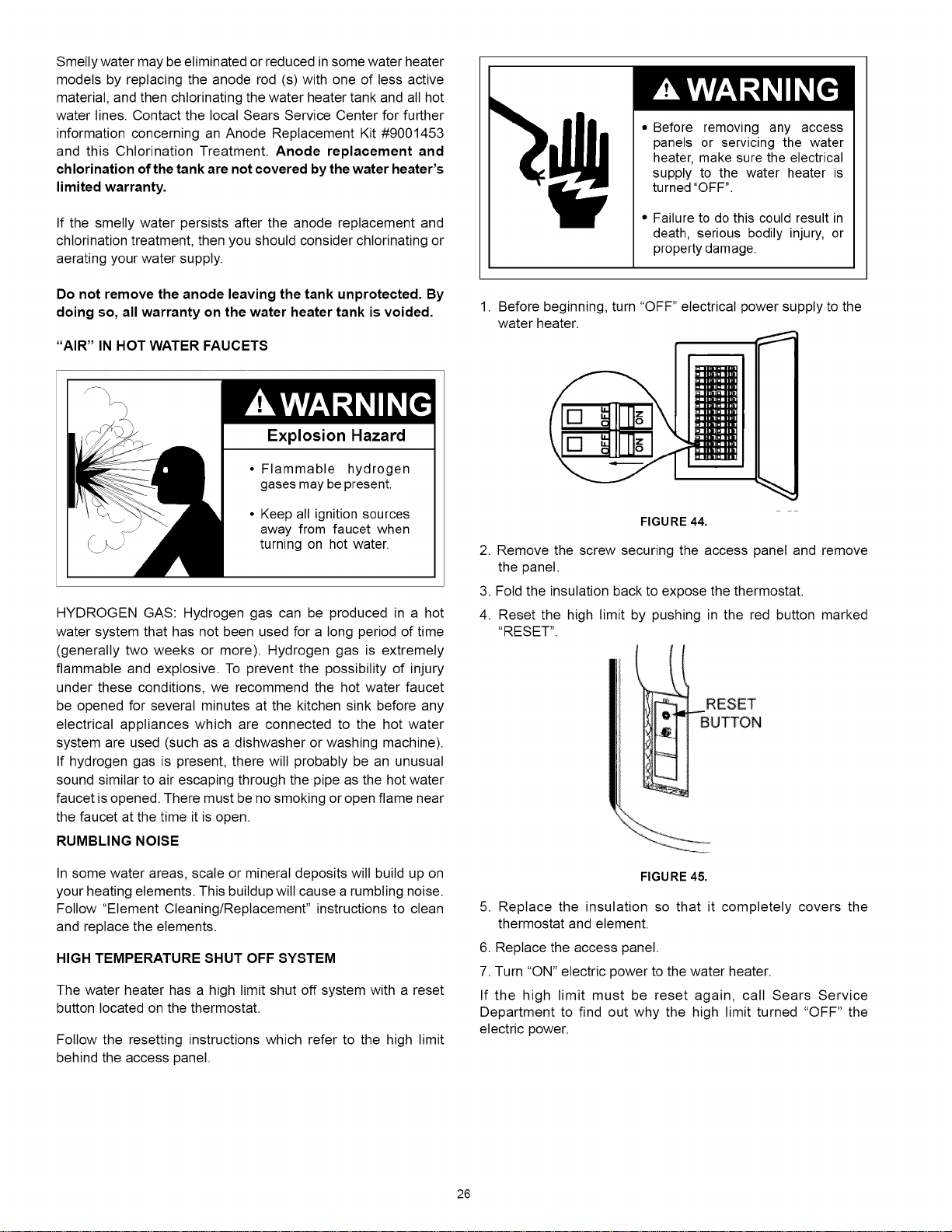
Smelly water may be eliminated or reduced in some water heater
models by replacing the anode rod (s) with one of tess active
material, and then chlorinating the water heater tank and all hot
water lines. Contact the local Sears Service Center for further
information concerning an Anode Replacement Kit #9001453
and this Chlorination Treatment. Anode replacement and
chlorination of the tank are not covered by the water heater's
limited warranty.
If the smelly water persists after the anode replacement and
chlorination treatment, then you should consider chlorinating or
aerating your water supply.
Do not remove the anode leaving the tank unprotected. By
doing so, all warranty on the water heater tank is voided.
"AIR" IN HOT WATER FAUCETS
Explosion Hazard
• Flammable hydrogen
gases may be present.
• Keep all ignition sources
away from faucet when
turning on hot water.
HYDROGEN GAS: Hydrogen gas can be produced in a hot
water system that has not been used for a long period of time
(generally two weeks or more). Hydrogen gas is extremely
flammable and explosive. To prevent the possibility of injury
under these conditions, we recommend the hot water faucet
be opened for several minutes at the kitchen sink before any
electrical appliances which are connected to the hot water
system are used (such as a dishwasher or washing machine).
If hydrogen gas is present, there wilt probably be an unusual
sound similar to air escaping through the pipe as the hot water
faucet is opened. There must be no smoking or open flame near
the faucet at the time it is open.
RUMBLING NOISE
In some water areas, scale or mineral deposits wilt build up on
your heating elements. This buildup wilt cause a rumbling noise.
Follow "Element Cleaning/Replacement" instructions to clean
and replace the elements.
HIGH TEMPERATURE SHUT OFF SYSTEM
The water heater has a high limit shut off system with a reset
button located on the thermostat.
Follow the resetting instructions which refer to the high limit
behind the access panel.
• Before removing any access
panels or servicing the water
heater, make sure the electrical
supply to the water heater is
turned "OFF".
• Failure to do this could result in
death, serious bodily injury, or
property damage.
1. Before beginning, turn "OFF" electrical power supply to the
water heater.
FIGURE 44.
2. Remove the screw securing the access panel and remove
the panel.
3. Fold the insulation back to expose the thermostat.
4. Reset the high limit by pushing in the red button marked
"RESET".
RESET
FIGURE 45.
5. Replace the insulation so that it completely covers the
thermostat and element.
6. Replace the access panel.
7. Turn "ON" electric power to the water heater.
If the high limit must be reset again, call Sears Service
Department to find out why the high limit turned "OFF" the
electric power.
26
NOT ENOUGH OR NO HOT WATER
1. In a new installation, the water heater may not be properly
connected. Make sure the cold water supply valve is open.
Review and check piping installation. Make sure that the
cold water line is connected to the cold water inlet to the
water heater and the hot water line to the hot water outlet
on the water heater.
2. Make sure the electrical supply to your water heater is "ON".
3. Check for loose or blown fuses in your water heater circuit.
Circuit breakers weaken with age and may not handle their
rated load and should be replaced.
4. Make certain the disconnect switch, if used, is in the "ON"
position.
5. Check to see the electric service to your house has not been
interrupted. If this is the case, contact the electric company.
6. Is the thermostat set to the desired temperature? See
"Temperature Regulation" section.
7. Ifyou had experienced very hot water and now no hot water,
the problem may be due to the high temperature shut off
system. See "High Temperature Shut Off System" in the
"Troubleshooting" section.
8. During very cold weather, the incoming water wilt also be
colder and it will require a longer time to become heated.
9. The hot water usage may exceed the capacity of the water
heater. Ifso, wait for water heater to recover after abnormal
demand. Also examine pipes and faucets for possible water
leaks.
10. If you can not determine the problem, then call the Sears
Service Department.
WATER IS TOO HOT
Adjust the thermostat to a lower setting. See the "Temperature
Regulation" section.
27
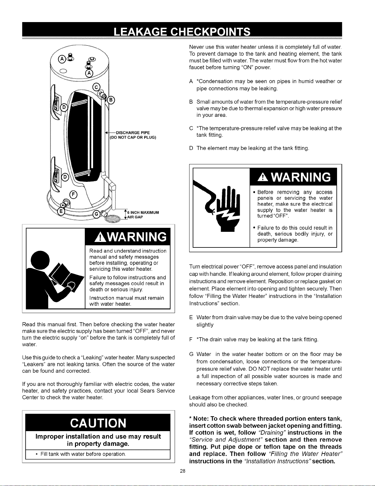
Never use this water heater unless it is completely full of water.
To prevent damage to the tank and heating element, the tank
must be filled with water. The water must flow from the hot water
faucet before turning "ON" power.
A*Condensation may be seen on pipes in humid weather or
pipe connections may be leaking.
B Small amounts of water from the temperature-pressure relief
valve may be due to thermal expansion or high water pressure
in your area.
C *The temperature-pressure relief valve may be leaking at the
tank fitting.
D The element may be leaking at the tank fitting.
Read and understand instruction
manual and safety messages
before installing, operating or
servicing this water heater.
Failure to follow instructions and
safety messages could result in
death or serious injury.
Instruction manual must remain
with water heater.
Read this manual first. Then before checking the water heater
make sure the electric supply has been turned "OFF", and never
turn the electric supply "on" before the tank is completely full of
water.
Use this guide to check a"Leaking" water heater. Many suspected
"Leakers" are not leaking tanks. Often the source of the water
can be found and corrected.
If you are not thoroughly familiar with electric codes, the water
heater, and safety practices, contact your local Sears Service
Center to check the water heater.
Improper installation and use may result
in property damage.
• Fill tank with water before operation.
28
• Before removing any access
panels or servicing the water
heater, make sure the electrical
supply to the water heater is
turned "OFF".
• Failure to do this could result in
death, serious bodily injury, or
property damage.
Turn electrical power "OFF", remove access panel and insulation
cap with handle. If leaking around element, follow proper draining
instructions and remove element. Reposition or replace gasket on
element. Place element into opening and tighten securely. Then
follow "Filling the Water Heater" instructions in the "Installation
Instructions" section.
E Water from drain valve may be due to the valve being opened
slightly
F *The drain valve may be leaking at the tank fitting.
GWater in the water heater bottom or on the floor may be
from condensation, loose connections or the temperature-
pressure relief valve. DO NOT replace the water heater until
a full inspection of all possible water sources is made and
necessary corrective steps taken.
Leakage from other appliances, water lines, or ground seepage
should also be checked.
* Note: To check where threaded portion enters tank,
insert cotton swab between jacket opening and fitting.
If cotton is wet, follow "Draining" instructions in the
"Service and Adjustment" section and then remove
fitting. Put pipe dope or teflon tape on the threads
and replace. Then follow "Fi//ing the Water Heater"
instructions in the "/nsta//ation/nstructions" section.
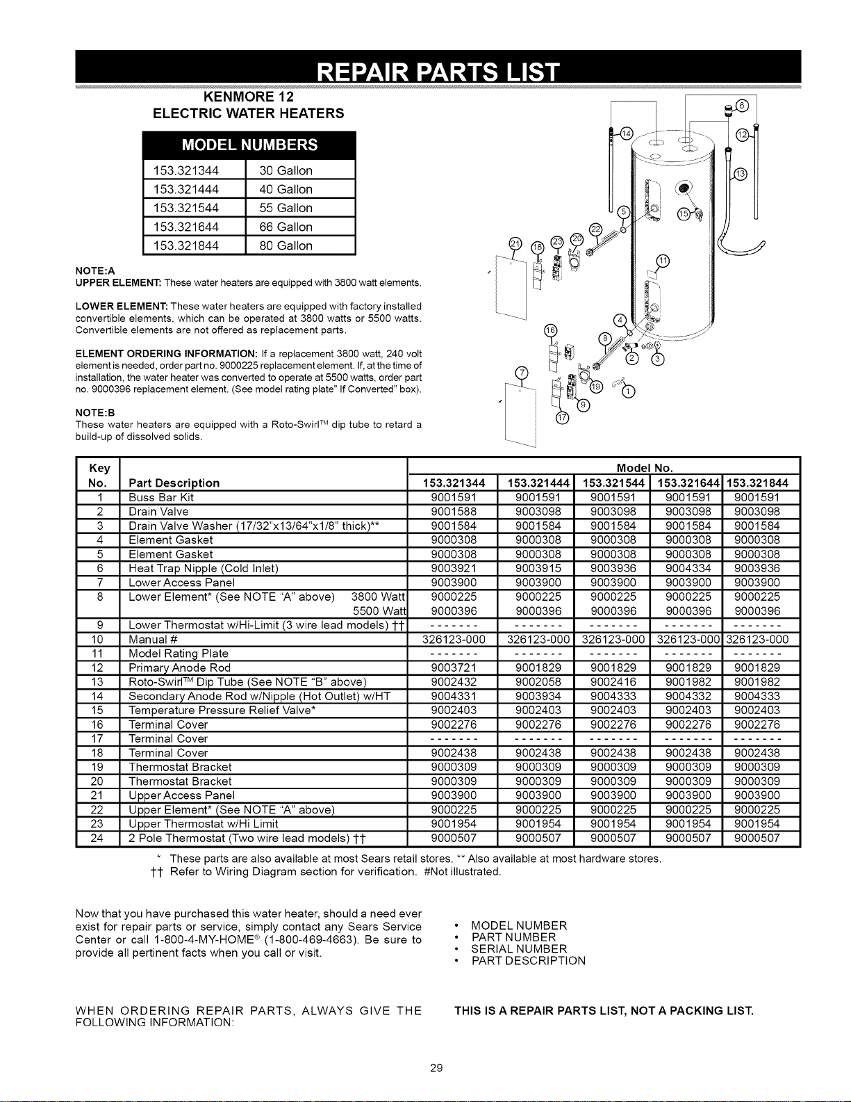
KENMORE12
ELECTRICWATERHEATERS
153.321344 30 Gallon
153.321444 40 Gallon
153.321544 55 Gallon
153.321644 66 Gallon
153.321844 80 Gallon
NOTE:A
UPPER ELEMENT: These water heaters are equipped with 3800 watt elements.
LOWER ELEMENT: These water heaters are equipped with factory installed
convertible elements, which can be operated at 3800 watts or 5500 watts.
Convertible elements are not offered as replacement parts.
ELEMENT ORDERING INFORMATION: If a replacement 3800 watt, 240 volt
element is needed, order part no. 9000225 replacement element. If, at the time of
installation, the water heater was converted to operate at 5500 watts, order part
no. 9000396 replacement element. (See model rating plate" If Converted" box).
NOTE:B
These water heaters are equipped with a Roto-Swirl TM dip tube to retard a
build-up of dissolved solids.
I
Key
No.
1
2
3
4
5
6
7
8
9
10
11
12
13
14
15
16
17
18
19
2O
21
22
23
24
Part Description
Buss Bar Kit
Drain Valve
Drain Valve Washer (17/32"xl 3/64"xl/8" thick)**
Element Gasket
Element Gasket
Heat Trap Nipple (Cold Inlet)
Lower Access Panel
Lower Element* (See NOTE "A" above) 3800 Watt
5500 Watt
Lower Thermostat w/Hi-Limit (3 wire lead models) 11
Manual #
Model Rating Plate
Primary Anode Rod
Roto-Swirl TM Dip Tube (See NOTE "B" above)
Secondary Anode Rod w/Nipple (Hot Outlet) w/HT
Temperature Pressure Relief Valve*
Terminal Cover
Terminal Cover
Terminal Cover
Thermostat Bracket
Thermostat Bracket
Upper Access Panel
Upper Element* (See NOTE "A" above)
Upper Thermostat w/Hi Limit
2 Pole Thermostat (Two wire lead models) 11
tt
153.321344
9001591
9001588
9001584
9000308
9000308
9003921
9003900
9000225
9000396
153.321444
9001591
9003098
9001584
9000308
9000308
9003915
9003900
9000225
9000396
Model No.
153.321544
9001591
9003098
9001584
9000308
9000308
9003936
9003900
9000225
9000396
153.321644
9001591
9003098
9001584
9000308
9000308
9004334
9003900
9000225
9000396
153.321844
9001591
9003098
9001584
9000308
9000308
9003936
9003900
9000225
9000396
326123-000 326123-000 326123-000 326123-000 326123-000
9003721
9002432
9004331
9002403
9002276
9002438
9000309
9000309
9003900
9000225
9001954
9000507
9001829
9002416
9004333
9002403
9002276
9002438
9000309
9000309
9003900
9000225
9001954
9000507
9001829
9002058
9003934
9002403
9002276
9002438
9000309
9000309
9003900
9000225
9001954
9000507
9001829
9001982
9004332
9002403
9002276
9002438
9000309
9000309
9003900
9000225
9001954
9000507
These parts are also available at most Sears retail stores. ** Also available at most hardware stores.
Refer to Wiring Diagram section for verification. #Not illustrated.
9001829
9001982
9004333
9002403
9002276
9002438
9000309
9000309
9003900
9000225
9001954
9000507
Now that you have purchased this water heater, should a need ever
exist for repair parts or service, simply contact any Sears Service
Center or call 1-800-4-MY-HOME <R_(1-800-469-4663). Be sure to
provide all pertinent facts when you call or visit.
• MODEL NUMBER
• PART NUMBER
• SERIAL NUMBER
• PART DESCRIPTION
WHEN ORDERING REPAIR PARTS, ALWAYS GIVE THE
FOLLOWING INFORMATION: THIS IS AREPAIR PARTS LIST, NOT A PACKING LIST.
29

30

31

Your Home
For troubleshooting, product manuals and expert advice:
managemylife
www.managemylife.com
For repair - in your home - of all major brand appliances,
lawn and garden equipment, or heating and cooling systems,
no matter who made it, no matter who sold it!
For the replacement parts, accessories and
owner's manuals that you need to do-it-yourself.
For Sears professional installation of home appliances
and items like garage door openers and water heaters.
1-800-4-MY-HOME ®(1-800-469-4663)
Call anytime, day or night (U.S.A. and Canada)
www.sears.com www.sears.ca
Our Home
For repair of carry-in items like vacuums, lawn equipment,
and electronics, call anytime for the location of your nearest
Sears Parts & Repair Service Center
1-800-488-1222 (U.S.A.) 1-800-469-4663 (Canada)
www.sears.com www.sears.ca
To purchase a protection agreement on a product serviced by Sears:
1-800-827-6655 (U.S.A.)
Para pedir servicio de reparaci6n
a domicilio, y para ordenar piezas:
1-888-SU-HOGAR ®
(1-888-784-6427)
www.sears.com s(98rs
1-800-361-6665 (Canada)
Au Canada pour service en fran£ais:
1-800-LE-FOYER M°
(1-800-533-6937)
www.sears.ca
® Registered Trademark /TMTrademark of KCD IP, LLC in the United States, or Sears Brands, LLC in other countries
® Marca Registrada /TMMarca de Fabrica de KCD IP, LLC en Estados Unidos, o Sears Brands, LLC in otros paises
MCMarque de commerce /MDMarque deposee de Sears Brands, LLC