SENP/14Z
GT
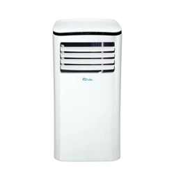
P O R TA B L E A I R C O N D I T I O N E R

Contents
Safety Precautions
Cautions
Preparations
Installation
Operation
Maintenance
Faults Diagnosis
Design and Compliance Notes
Sociable Remark
2
3
4
5
8
1 1
1 2
1 3
1 4
------------- -------------
----------------- --------------
----------------- ----------------
------------------- ------------ --
----------------- ---------------
--------------- --------------
--------------- -------------
------------------- ---------------
------ ------ ------
1
Safety Precautions
-Installation must be performed according to the installation instructions. Improper installation
can cause water leakage, electrical shock, or fire.
-Use only the included accessories and parts, and specified tools for the installation. Using
non-standard parts can cause water leakage, electrical shock, fire, and injury or property damage.
-Make sure that the outlet you are using is grounded and has the appropriate voltage. The
power cord is equipped with a three-prong grounding plug to protect against shock. Voltage
information can be found on the nameplate of the unit.
-Your unit must be used in a properly grounded wall receptacle. If the wall receptacle you
intend to use is not adequately grounded or protected by a time delay fuse or circuit breaker
(the fuse or circuit breaker needed is determined by the maximum current of the unit. The
maximum current is indicated on the nameplate located on unit), have a qualified electrician
install the proper receptacle.
-Install the unit on a flat, sturdy surface. Failure to do so could result in damage or excessive
noise and vibration.
-
The unit must be kept free from obstruction to ensure proper function and to mitigate safety hazards.
-DO NOT modify the length of the power cord or use an extension cord to power the unit.
-DO NOT share a single outlet with other electrical appliances. Improper power supply can
cause fire or electrical shock.
-DO NOT install your air conditioner in a wet room such as a bathroom or laundry room. Too
much exposure to water can cause electrical components to short circuit.
-
DO NOT install the unit in a location that may be exposed to combustible gas, as this could cause fire.
-The unit has wheels to facilitate moving. Make sure not to use the wheels on thick carpet or to roll
over objects, as these could cause tipping.
-DO NOT operate a unit that it has been dropped or damaged.
-The appliance with electric heater shall have at least 1 meter space to the combustible materials.
-Do not touch the unit with wet or damp hands or when barefoot.
-If the air conditioner is knocked over during use, turn off the unit and unplug it from the main power
supply immediately. Visually inspect the unit to ensure there is no damage. If you suspect the unit
has been damaged, contact a technician or customer service for assistance.
-In a thunderstorm, the power must be cut off to avoid damage to the machine due to lightning.
-Your air conditioner should be used in such a way that it is protected from moisture. e.g.
condensation, splashed water, etc. Do not place or store your air conditioner where it can fall or be
pulled into water or any other liquid. Unplug immediately if it occurs.
-
All wiring must be performed strictly in accordance with the wiring diagram located inside of the unit.
-The unit's circuit board(PCB) is designed with a fuse to provide overcurrent protection. The
specifications of the fuse are printed on the circuit board, such as: T 3.15A/250V, etc.
WARNING: To prevent death or injury to the user or other people and property damage,
the following instructions must be followed. Incorrect operation due to ignoring of
instructions may cause death, harm or damage.
This symbol indicates that ignoring instructions may cause death or serious injury.
2

Cautions
-This appliance can be used by children aged from 8 years and above and person with
reduced physical, sensory or mental capabilities or lack of experience and knowledge if they
have been given supervision or instruction concerning use of the appliance in a safe way
and understand the hazards involved. Children shall not play with the appliance. Cleaning
and user maintenance shall not be made by children without supervision. (be applicable for
the European Countries)
-This appliance is not intended for use by persons (including childern) with reduced physical,
sensory or mental capabilities or lack of experience and knowledge, unless they have been
given supervision or instruction concerning use of the appliance by a person responsible for
their safety. (be applicable for other countries except the European Countries )
-Children should be supervised to ensure that they do not play with the appliance.
Children
must be supervised around the unit at all times.
-If the supply cord is damaged, it must be replaced by the manufacturer,its service agent or
similarly qualified persons in order to avoid a hazard.
-
Prior to cleaning or other maintenance, the appliance must be disconnected from the supply mains.
-Do not remove any fixed covers. Never use this appliance if it is not working properly, or if it
has been dropped or damaged.
-Do not run cord under carpeting. Do not cover cord with throw rugs, runners, or similar
coverings. Do not route cord under furniture or appliances. Arrange cord away from traffic
area and where it will not be tripped over.
-Do not operate unit with a damaged cord, plug, power fuse or circuit breaker. Discard unit or
return to an authorized service facility for examination and/or repair.
-To reduce the risk of fire or electric shock, do not use this fan with any solid-state speed
control device.
-The appliance shall be installed in accordance with national wiring regulations.
-Contact the authorised service technician for repair or maintenance of this unit.
-Contact the authorised installer for installation of this unit.
-Do not cover or obstruct the inlet or outlet grilles.
-Do not use this product for functions other than those described in this instruction manual.
-Before cleaning, turn off the power and unplug the unit.
-Disconnect the power if strange sounds, smell, or smoke comes from it.
-Do not press the buttons on the control panel with anything other than your fingers.
-Do not remove any fixed covers. Never use this appliance if it is not working properly, or if it
has been dropped or damaged.
-Do not operate or stop the unit by inserting or pulling out the power cord plug.
-Do not use hazardous chemicals to clean or come into contact with the unit. Do not use the
unit in the presence of inflammable substances or vapour such as alcohol, insecticides, petrol,etc.
-Always transport your air conditioner in a vertical position and stand on a stable, level surface
during use.
-
Always contact a qualified person to carry out repairs. If the damaged power supply cord must be
replaced with a new power supply cord obtained from the product manufacturer and not repaired.
-Hold the plug by the head of the power plug when taking it out.
-Turn off the product when not in use.
Cautions
3
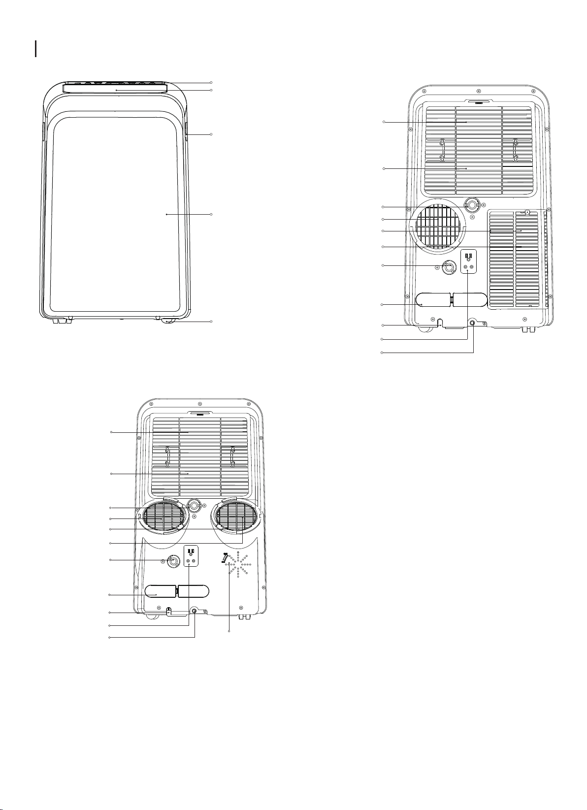
Preparation
rear
MODEAL A
MODEAL B
power plug socket
power cord buckle
bottom tray
drain outlet
power cord outlet
drain outlet
(only for pump
heating mode)
upper air filter
(behind the grille)
upper air intake
air outlet
lower air filter
lower air intake
drain outlet
4
front
rear
control panel
handle
(both sides)
horizontal louver
blade
(swing automatically)
Caster
power plug socket
power cord buckle
vent control
bottom tray
drain outlet
power cord outlet
drain outlet
(only for pump
heating mode)
upper air filter
(behind the grille)
upper air intake
air outlet
lower air filter
lower air intake
drain outlet
Panel
SCALE 0.500
Accessories
North America
Check your window size and choose the fit window slider.
Part Description
1 pc 2 pc
1 pc 2 pc
1 pc 2 pc
1 pc
1 pc
1 pc
2 pc
2 pc
1 pc
2 pc
1 pc
1 pc
1 pc
1 pc
1 pc
1 pc
1 set
1 set
Unit Adaptor
Window Slider Adaptor
Window Slider A
Window Slider A
Window Slider B
Window Slider C(optional)
Exhaust Hose
Bolt
Foam Seal A (Adhesive)
Foam Seal B (Adhesive)
Foam Seal C (Non-adhesive)
Security Bracket and Screw
Drain Hose
Drain Hose Adaptor(only for
heat pump mode)
Quantity
single-exhaust
unit(MODEL A)
double-exhaust
unit(MODEL B)
Part Description Quantity
2 pc
1 pc
Bolt(optional)
Remote Controller
and Battery
ON/OF F
TEMP
SHOR T
CU T
TIME R
ON
TIME R
OFF
MODE
FAN
SLE E P
SWIN G
LED
NOTE: Items with are optional. Slight variations in design may occur.
*
Foam Seal A (Adhesive)(optional)
Foam Seal B (Adhesive)(optional)
Foam Seal C (Non-adhesive)
(optional)
*
*
*
*
*
Power Cord Buckle
Installation
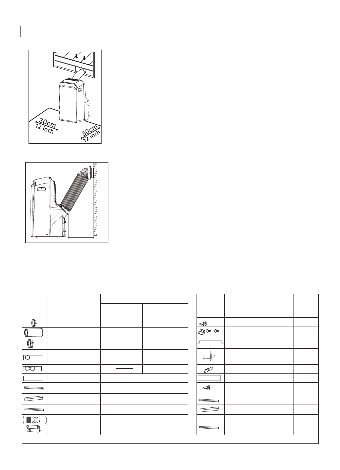
Choosing The Right Location
Recommend Installation
Your installation location should meet the following requirements:
-Make sure that you install your unit on an even surface to
minimize noise and vibration.
-The unit must be installed near a grounded plug, and the
Collection Tray Drain (found on the back of the unit) must be
accessible.
-The unit should be located at least 30cm (12”) from the nearest
wall to ensure proper air conditioning.
-DO NOT cover the Intakes, Outlets or Remote Signal Receptor
of the unit, as this could cause damage to the unit.
NOTE:
All the illustrations in the manual are for explanation
purpose only. Your machine may be slightly different.
The actual shape shall prevail.
The unit can be controlled by the unit control panel
alone or with the remote controller. This manual does
not include Remote Controller Operations, see the
<<Remote Controll Illustration>> packed with the unit
for details.
When there are wide differences between
“INSTRUCTION MANUAL” and “Remote controll
Illustration” on function description, the description on
“INSTRUCTION MANUAL ” shall prevail.
50cm
19.7inch
Tools Needed
-Medium Philips screwdriver; -Tape measure or ruler; -Knife or scissors; -Saw (optional, to shorten window
adaptor for narrow windows)
5
Installation
6
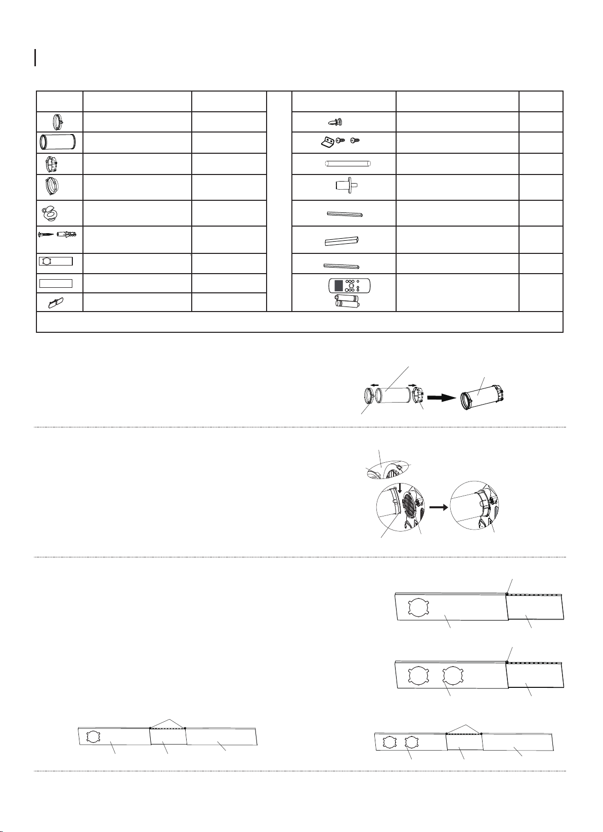
Window Installation Kit
Press the exhaust hose into the window slider adaptor
and unit adaptor, clamp automatically by elastic buckles
of the adaptors.
Step One: Preparing the Exhaust Hose assembly
Step Two: Install the Exhaust hose assembly to the unit
Insert unit adaptor of the Exhaust hose assembly into the
lower groove of the air outlet of the unit while the hook of
the adaptor is aligned with the hole seat of the air outlet
and slide down the Exhaust hose assembly along the arrow
direction for installation.
Unit adaptor
Window slider
adaptor
Exhaust hose
Press into Press into
Exhaust hose
assembly
Make sure the hook of the adaptor is aligned
with the hole seat of the air outlet.
Hook
Hole Seat
Lower groove
adaptor
Type round:
Make sure the adaptor is
inserted into the lower
groove of the air outlet.
Step Three: Preparing the Adjustable Window Slider
1. Depending on the size of your window, adjust the size of the
window slider.
2. If the length of the window requires two window sliders, use the bolt
to fasten the window sliders once they are adjusted to the proper
length.
3. For some models, if the length of the window requires three window
sliders(optional), use two bolts to fasten the window sliders once they
are adjusted to proper length.
Window slider A
MODEL A
MODEL A
MODEL B
MODEL B
Window slider B
Bolt
Window slider A Window slider B
Bolt
or
or
Window slider A Window slider B
Window slider C
Bolts
Window slider A Window slider B
Window slider C
Bolts
Other Regions
Part Description
1 pc
1 pc
1 pc
1 pc
1 pc
1 pc
1 pc
1 pc
1 pc
2 pc
1 pc
1 pc
1 pc
2 pc
1 set
1 set
Unit Adaptor
Window Slider Adaptor
Window Slider A
Window Slider B
Exhaust Hose
Bolt
Foam Seal A (Adhesive)
Foam Seal B (Adhesive)
Foam Seal C (Non-adhesive)
Security Bracket and Screw
Drain Hose
Drain Hose Adaptor(only for
heat pump mode)
Quantity Part Description Quantity
Remote Controller
and Battery
ON/OF F
TEMP
SHOR T
CU T
TIME R
ON
TIME R
OFF
MODE
FAN
SLE E P
SWIN G
LED
4 set
Wall Exhaust Adaptor A
(only for wall installation)
Wall Exhaust Adaptor B(with cap)
(only for wall installation)
Screw and anchor
(only for wall installation)
NOTE: Items with are optional. Slight variations in design may occur.
*
*
*
*
*
*
*
*
*
*
*
*
Power Cord Buckle
Installation
7
3.Cut the non-adhesive foam seal C strip to match the width of the
window. Insert the seal between the glass and the window frame to
prevent air and insects from getting into the room.
4.If desired, install the security bracket with 2 screws as shown.
2 Screws
Security Bracket
Foam seal B
(Adhesive type-shorter)
Foam seal A
(Adhesive type)
Window slider A
Window slider B
(if required)
Foam seal C
(Non-adhesive type)
Foam seal C
(Non-adhesive type)
2 Screws
Security
Bracket
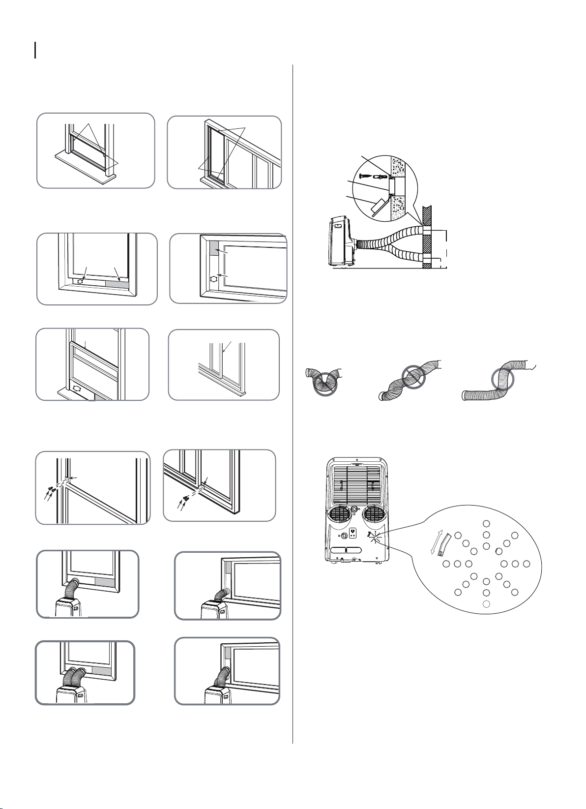
Type 2: Wall Installation(optional)
1.Cut a 125mm (4.9inch) hole into the wall for the Wall
Exhaust Adaptor B. 2.Secure the Wall Exhaust Adaptor B
to the wall using the four Anchors and Screws provided in
the kit. 3.Connect the Exhaust Hose Assembly(with Wall
Exhaust Adaptor A) to the Wall Exhaust Adaptor B.
Note: Cover the hole using the
adaptor cap when not in use.
Note: To ensure proper function, DO NOT overextend or
bend the hose. Make sure that there is no obstacle around
the air outlet of the exhaust hose (in the range of 500mm)
in order to the exhaust system works properly. All the
illustrations in this manual are for explanation purpose only.
Your air conditioner may be slightly different. The actual
shape shall prevail.
max 120cm or 47 inch
min 30cm or 12 inch
Expansion anchor
position
Adaptor cap
Wall Exhaust
Adaptor B
Note: Once the Exhaust Hose assembly and Adjustable Window Slider
are prepared, choose from one of the following installation methods.
1.Cut the adhesive foam seal A and B strips to the
proper lengths, and attach them to the window sash
and frame as shown.
or
or
or
or
or
or
MODEL A
MODEL B
2.Insert the window slider assembly into the window opening.
Type 1: Hung Window or Sliding Window Installation(optional)
Foam seal B
(Adhesive type-shorter)
Foam seal A
(Adhesive type)
Window slider A
Window slider B
(if required)
VENT CONTROL feature
The Vent Control is located at the back of the air
conditioner. The OPEN position removes stale air
from the room and exhausts it to the outside. Fresh
air is drawn in through normal passages in the home.
When not need to circulate the room air, set Vent
Control to CLOSE position. This function is only
applicable for MODEL B.
CLOSE
OPEN
5.Insert the window slider adaptor into the hole of the window slider.
13
Design and Compliance Notes
Design Notice
Energy Rating Information
The design and specifications are subject to change without prior notice for
product improvement. Consult with the sales agency or manufacturer for details.
Any updates to the manual will be uploaded to the service website, please check
for the latest version.
The Energy Rating for this unit is based on an installation using an
un-extended exhaust duct without window slider adaptor or wall exhaust
adaptor A (as shown in the Installation section of this manual).
Unit Temperature Range
Note About Fluorinated Gasses
-Fluorinated greenhouse gases are contained in hermetically sealed equipment. For specific information on
the type, the amount and the CO2 equivalent in tonnes of the fluorinated greenhouse gas(on some models),
please refer to the relevant label on the unit itself.
-Installation, service, maintenance and repair of this unit must be performed by a certified technician.
-Product uninstallation and recycling must be performed by a certified technician.
≤
Cool 17-35°C (62-95°F)
Dry
Heat(pump heat
mode)
Heat(electrical
heat mode)
13-35°C (55-95°F)
5-30°C (41-86°F)
30°C (86°F)
Mode Temperature Range
Sociable Remark
When using this unit in the European countries, the following information must be followed:
DISPOSAL: Do not dispose this product as unsorted municipal waste. Collection of such waste
separately for special treatment is necessary.
It is prohibited to dispose of this appliance in domestic household waste.
For disposal, there are several possibilities:
A) The municipality has established collection systems, where electronic waste can be disposed of at
least free of charge to the user.
B) When buying a new product, the retailer will take back the old product at least free of charge.
C) The manufacture will take back the old appliance for disposal at least free of charge to the user.
D) As old products contain valuable resources, they can be sold to scrap metal dealers.
Wild disposal of waste in forests and landscapes endangers your health when hazardous substances
leak into the ground-water and find their way into the food chain.
14


AIR CONDITIONER
REMOTE CONTROL ILLUSTRATION
Thank you very much for purchasing our air conditioner.
Please read this owner's manual carefully before using
your air conditioner. Keep it for future reference.
11
CONTENTS
2
3
4
5
6
13
Handling the remote control.... ......................................................
Remote control Specifications......................................................
Function buttons .................. .........................................................
Remote LED screen indicators .....................................................
How to use the basic functions......................................................
How to use the advanced functions ..............................................
22
Model
Rated Voltage
8m
3.0V(Dry batteries R03/LR03 2)
Environment
Signal Receiving Range
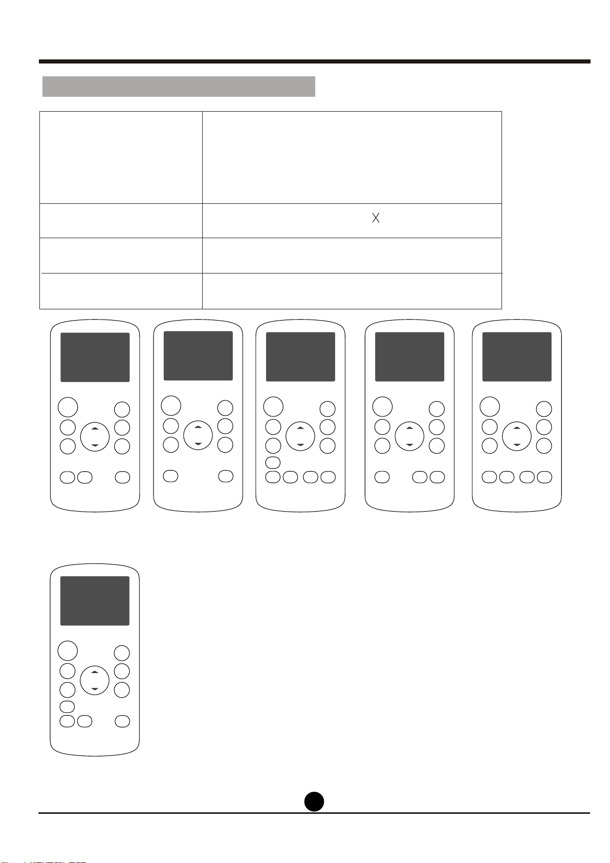
RG57H(B)/BG(C)E; RG57H1(B)/BG(C)E; RG57H2(B)/BG(C)EF;RG57H3(B)/BG(C)EFU1;
RG57H3(B)/BG(C)EF;RG57H1(B)/BG(C)E-M;RG57H(B)/BG(C)EU1;RG57H4(B)/BG(C)EFU1;
RG57H(B)/BG(C)E-M;RG57H(B)/BG(C)EU1-M;RG57H3(B)/BG(C)EFU1-M;
RG57H1(B)/BG(C)EU1-M;RG57H5(B)/BG(C)CEU1;RG57H5(B)/BG(C)CE;RG57H1(B)/BG(C)EU1;
RG57H2(B)/BG(C)EFU1;RG57H3(B)/BG(C)EF;RG57H4(B)/BG(C)EF;RG57H2(B)/BG(C)EF-M;
RG57H2(B)/BG(C)EFU1-M
Remote Control Specifications
ON/OFF
TEMP
SHORT
CUT
TIMER
ON
TIMER
OFF
MODE
FAN
SLEEP
SWING
LED
ON/OFF
TEMP
SHORT
CUT
TIMER
ON
TIMER
OFF
MODE
FAN
LED
ON/OFF
TEMP
SHORT
CUT
TIMER
ON
TIMER
OFF
MODE
FAN
SLEEP
FOLLOW
ON/OFF
TEMP
SHORT
CUT
TIMER
ON
TIMER
OFF
MODE
FAN
LED
RG57H(B)/BG(C)E
SLEEP
SWING
ION
LED
ME
SLEEP
FOLLOW
ME
RG57H1(B)/BG(C)E;
RG57H1(B)/BG(C)E-M
RG57H1(B)/BG(C)EU1-M
RG57H1(B)/BG(C)EU1
RG57H2(B)/BG(C)EF
RG57H2(B)/BG(C)EF-M
RG57H2(B)/BG(C)EFU1
RG57H2(B)/BG(C)EFU1-M
RG57H3(B)/BG(C)EF
RG57H3(B)/BG(C)EFU1
RG57H3(B)/BG(C)EFU1-M
RG57H3(B)/BG(C)EF-M
OOO O
-5 C~60 C(23 F~140 F)
RG57H(B)/BG(C)EU1
RG57H(B)/BG(C)EU1-M
RG57H(B)/BG(C)E-M
RG57H4(B)/BG(C)EFU1
RG57H4(B)/BG(C)EF
ON/OFF
TEMP
SHORT
CUT
TIMER
ON
TIMER
OFF
MODE
FAN
SLEEP
FOLLOW
SWING
LED
ME
ON/OFF
TEMP
SHORT
CUT
TIMER
ON
TIMER
OFF
MODE
FAN
SLEEP
SWING
ION
LED
RG57H5(B)/BG(C)E
RG57H5(B)/BG(C)EU1
33
Before you begin using your new air conditioner, make sure to familiarize yourself with its remote
control. The following is a brief introduction to the remote control itself. For instructions on how to
operate your air conditioner, refer to the How to Use Basic Functions section of this manual.
SHORT CUT
Sets and activates your
favorite pre-settings.
ON/OFF
Turns the unit on or off.
MODE
Scrolls through operation
modes as follows:
AUTO
g
COOL
g
DRY
g
HEAT
g
FAN
FAN SPEED
Selects fan speeds in
the following order:
AUTO g LOW g
MED g HIGH
SLEEP
Saves energy during
sleeping hours.
ION
TEMPp
Increases temperate in
OO
1 C(1 F) increments.
Max. temperature is
OO
30 C(86 F) .
TEMPq
Decreases temperate in
OO
1 C(1 F) increments.
Min. temperature is
OO
17 C(62 F) .
TIMER ON
Sets timer to turn unit
on (see How to Use
Basic Functions for
instructions)
TIMER OFF
Sets timer to turn unit
off (see How to Use
Basic Functions for
instructions)
SWING
Starts and stops louver
movement.
LED
Turns indoor unit s LED
,
FOLLOW ME
Temperature sensing
and room temperature
display button.
ON/OFF
TEMP
SHORT
CUT
TIMER
ON
TIMER
OFF
MODE
FAN
LED
Press this button, the
Ionizer is energized and
will help to remove pollen
and impurities from the
air.
If you are sensitive to
light when you go to
sleep, you can press the
LED button to turn off
the LED display on the
unit. Press the button
again to turn it back on.
Function Buttons
ION
SLEEP
FOLLOW
SWING
ME
display on and off.
NOTE:
Swing, Ion, Follow me and Med fan speed features are optional.
NOTE Please do not select
HEAT mode if the machine you
purchased is cooling only type.
Heat mode is not supported by
the cooling only appliance.
NOTE: Press and hold
and buttons together for
3 seconds will alternate the
temperature display
OO
between the C & F scale.
q
p
NOTE: MED is optional.
44
NOT SURE WHAT A FUNCTION DOES?
Refer to the How to Use Basic Functions and
How to Use Advanced Functions sections
of this manual for a detailed description of
how to use your air conditioner.
SPECIAL NOTE
Button designs on your unit may differ
slightly from the example shown.
If the unit does not have a particular
function, pressing that function s button
on the remote control will have no effect.
When there are wide differences between
Remote control Illustration and
USER'S MANUAL on function description,
the description of USER'S MANUAL
shall prevail.
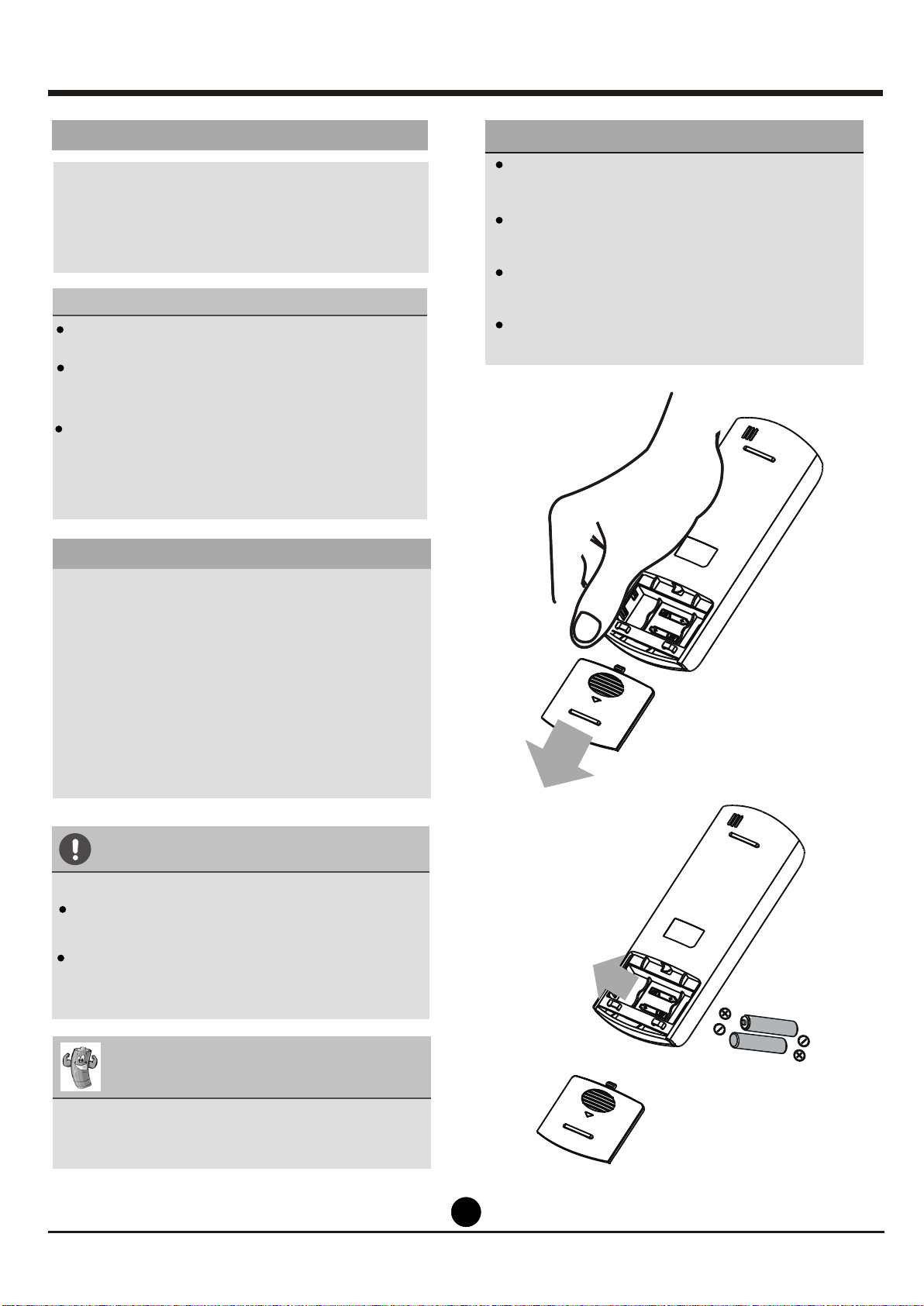
TIPS FOR USING REMOTE CONTROL
The remote control must be used within 8
meters of the unit.
The unit will beep when remote signal is
received.
Curtains, other materials and direct sunlight
can interfere with the infrared signal receiver.
Remove batteries if the remote will not be
used more than 2 months.
Inserting and Replacing Batteries
Your air conditioning unit comes with two AAA
batteries. Put the batteries in the remote control
before use.
1. Slide the back cover from the remote
Control downward, exposing the battery
compartment.
2. Insert the batteries, paying attention to match
up the (+) and (-) ends of the batteries with
the symbols inside the battery compartment.
3. Slide the battery cover back into place.
BATTERY NOTES
For optimum product performance:
Do not mix old and new batteries, or
batteries of different types.
Do not leave batteries in the remote control
if you don t plan on using the device for
more than 2 months.
BATTERY DISPOSAL
Do not dispose of batteries as unsorted
municipal waste. Refer to local laws for
proper disposal of batteries.
,
,
Handling The Remote Control
,
,
,
,
,
,
,
,
,
,
,
,
55
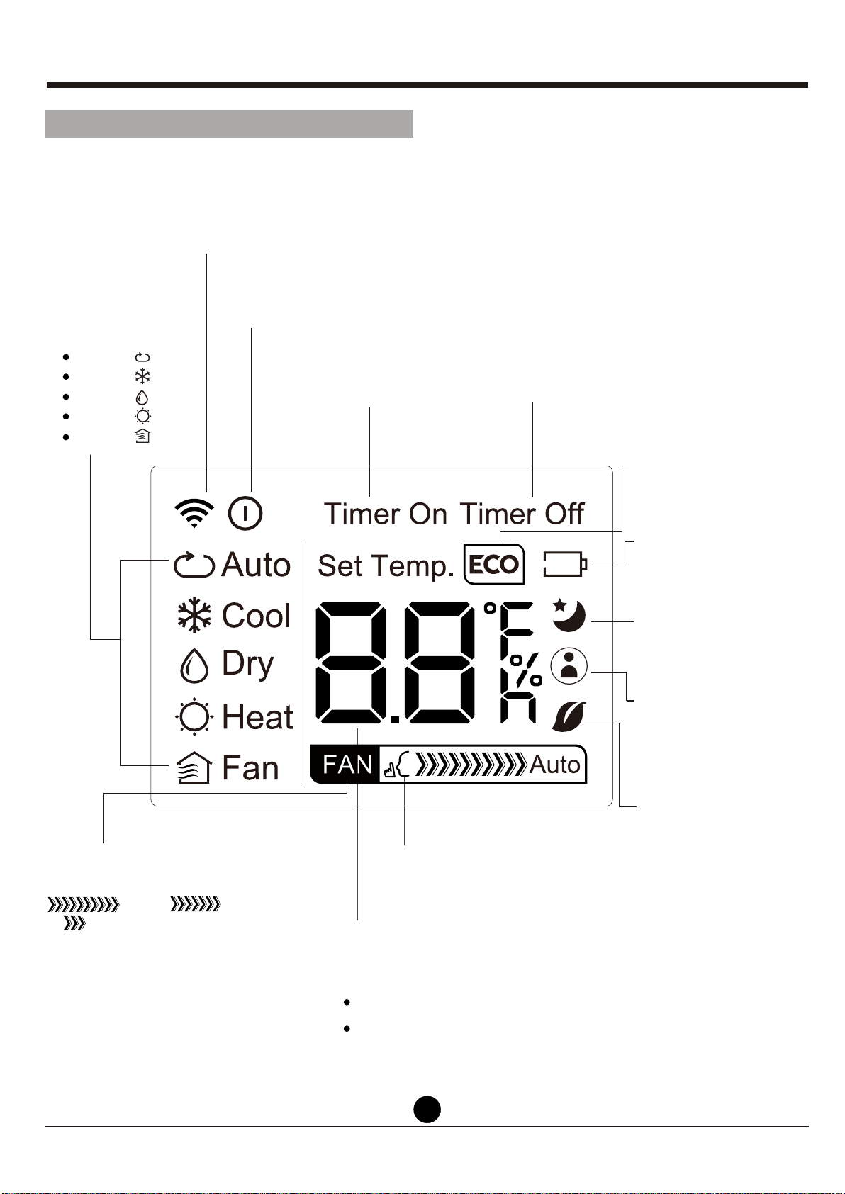
MODE display
Displays the current
mode, including:
AUTO
COOL
DRY
HEAT
FAN
Transmission Indicator
Lights up when remote sends
signal to unit
ON/OFF display
Appears when the unit is turned on,
and disappears when it is turned off
TIMER ON display
Displays when TIMER
ON is set
TIMER OFF display
Displays when TIMER
OFF is set
SLEEP display
Battery display
SILENT display
ECO display
Displays when
SLEEP function
is activated
FOLLOW ME
display
Indicates that
the FOLLOW ME
function is on
FAN SPEED display
Displays selected FAN SPEED:
HIGH, MED,
or LOW
This display is blank when
set to AUTO speed.
Temperature/Timer display
Displays the set temperature by default, or timer setting
when using TIMER ON/OFF functions
oOO
Temperature range: 17-30 C(62 F-86 F)
Timer setting range: 0-24 hours
This display is blank when operating in FAN mode.
Not available for this unit
Not available for
this unit
Not available for
this unit
Low battery
detection
Remote LED Screen Indicators
NOTE: MED is optional.
66
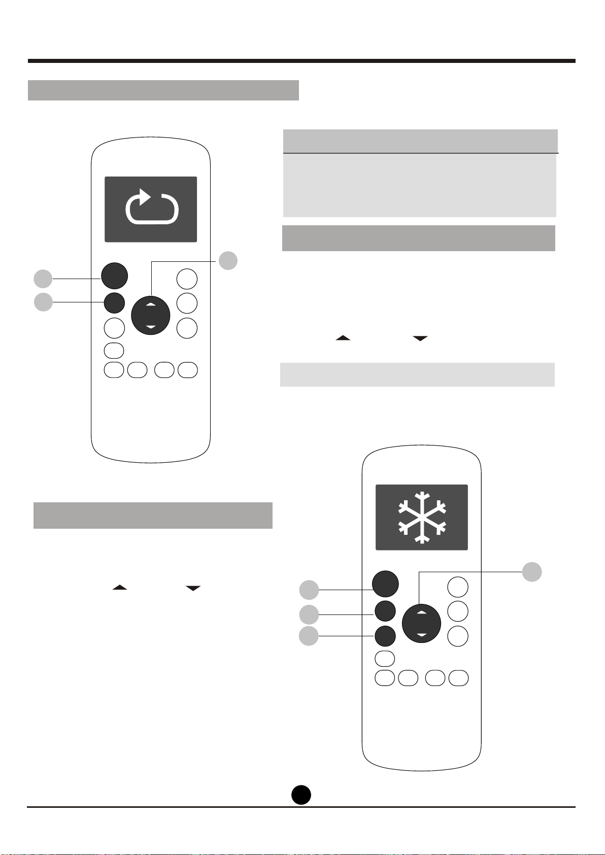
3. Press the FAN button to select the
fan speed: AUTO, LOW, MED,or
HIGH.
4. Press the ON/OFF button to start the
unit.
1. Press the MODE button to select
COOL mode.
2. Set your desired temperature using
the Temp or Temp button.
In AUTO mode, the unit will automatically
select the COOL, FAN, HEAT or DRY mode
based on the set temperature.
1. Press the MODE button to select Auto mode.
2. Set your desired temperature using the
Temp or Temp button.
3. Press the ON/OFF button to start the unit.
,
NOTE: FAN SPEED can t be set in Auto mode.
SETTING TEMPERATURE
AUTO operation
The operating temperature range for units is
OOO
17-30 C(62 F-86 F).
You can increase or
OO
decrease the set tmeperature in 1 C(1 F)
increments.
COOL operation
1
3
2
1
3
2
4
How To Use The Basic Functions
ON/OFF
ON/OFF
TEMP
TEMP
SHORT
CUT
SHORT
CUT
TIMER
ON
TIMER
ON
TIMER
OFF
TIMER
OFF
MODE
MODE
FAN
FAN
SLEEP
SLEEP
LED
LED
FOLLOW
ION
SWING
ME
FOLLOW
ION
SWING
ME
77
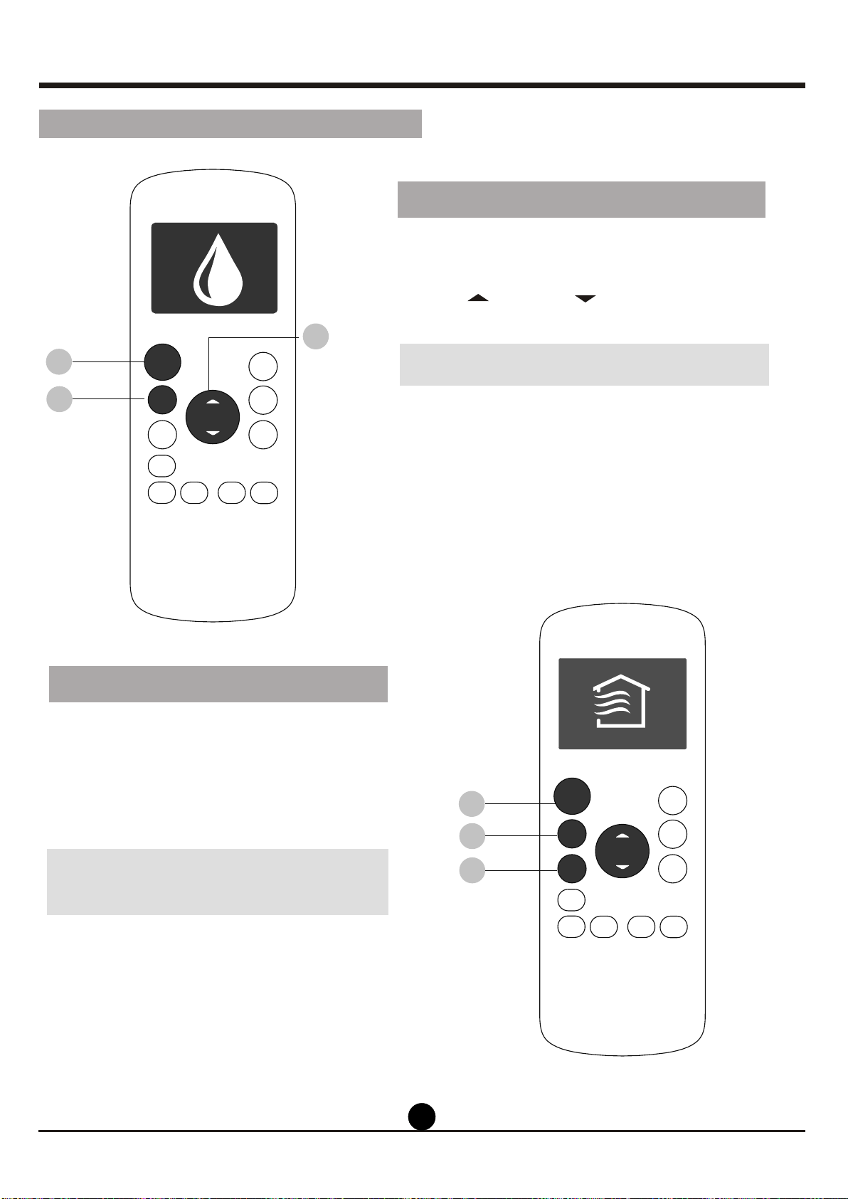
1. Press the MODE button to select DRY
mode.
2. Set your desired temperature using the
Temp or Temp button.
3. Press the ON/OFFbutton to start the unit.
,
NOTE: FAN SPEED can t be changed in
DRY mode.
1. Press the MODE button to select FAN
mode.
2. Press FAN button to select the fan
speed: AUTO, LOW, MED or HIGH.
3. Press the ON/OFFbutton to start the
unit.
,
NOTE: You can t set temperature in FAN
mode. As a result, your remote control s
LCD screen will not display temperature.
DRY operation(dehumidifying)
FAN operation
,
1
1
2
3
3
2
How To Use The Basic Functions
ON/OFF
TEMP
SHORT
CUT
TIMER
ON
TIMER
OFF
MODE
FAN
LED
ON/OFF
TEMP
SHORT
CUT
TIMER
ON
TIMER
OFF
MODE
FAN
SLEEP
LED
ION
SLEEP
FOLLOW
SWING
ME
ION
FOLLOW
SWING
ME
88
3. Press the FAN button to select the
fan speed: AUTO, LOW, MED,or HIGH.
4. Press the ON/OFF button to start the
unit.
1. Press the MODE button to select
HEAT mode.
2. Set your desired temperature using
the Temp or Temp button.
HEAT operation
NOTE: As outdoor temperature drops,the
performance of your unit s HEAT function
may be affected. In such instances, we
recommend using this air conditioner in
conjunction with other heating appliance.
,
1
3
2
4
How To Use The Basic Functions
ON/OFF
TEMP
SHORT
CUT
TIMER
ON
TIMER
OFF
MODE
FAN
SLEEP
LED
FOLLOW
ION
SWING
ME
99
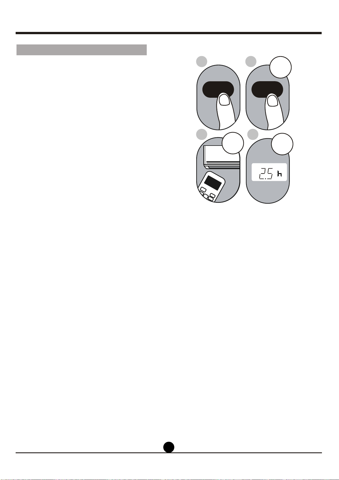
2. Press the TIMER ON button repeatedly
to set the time when you want the unit to
turn on.
3. Wait 2 seconds, then the TIMER ON
function will be activated. The digital
display on your remote control will then
return to the temperature display.
Example: Setting unit to turn on after 2.5
hours.
2sec
ON/OFF
MODE
FAN
SHORT
CUT
TIMER ON
TIMER OF
F
TEMP
S
L
E
EP
1sec
x5
1
3
2
4
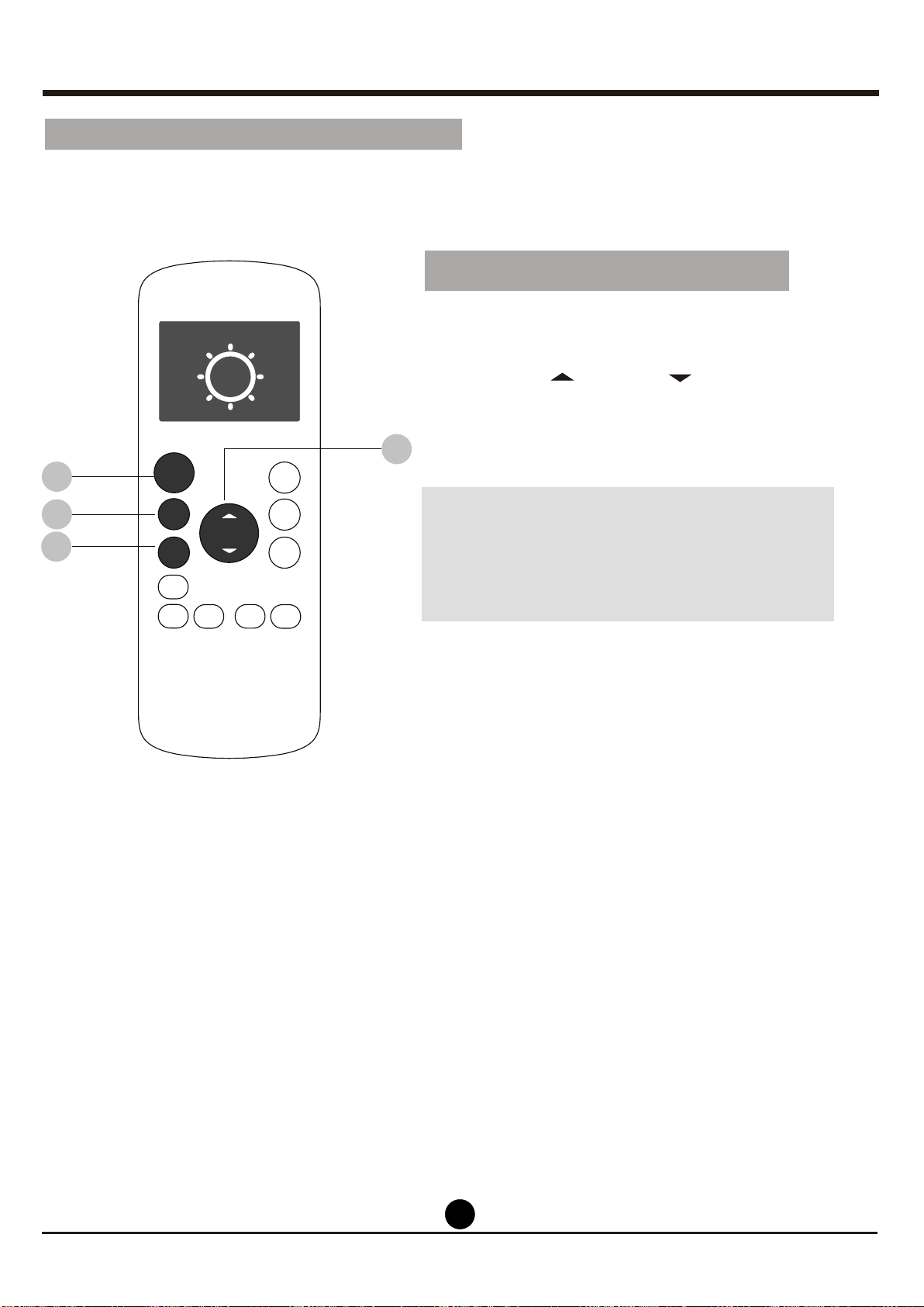
1.
This number indicates the
amount of time after the current time
that you want the unit to turn on.
For example, if you set TIMER ON for
2 hours, will appear on the
screen, and the unit will turn on after
2 hours.
Press the TIMER ON button. By
default, the last time period that you
set and an "h" (indicating hours)will
appear on the display.
Note:
" 2.0h "
TIMER ON function
The TIMER ON function allows you to set
a period of time after which the unit will
automatically turn on, such as when you
come home from work.
Your air conditioning unit has two
timer-related functions:
TIMER ON- sets the amount of timer after
which the unit will automatically turn on.
TIMER OFF- sets the amount of time after
which the unit will automatically turn off.
TIMER ON TIMER ON
Setting the TIMER function
1010
NOTE:
" 0.0h "
When setting the TIMER ON or
TIMER OFF functions, up to 10 hours,
the time will increase in 30 minute
increments with each press. After 10
hours and up to 24, it will increase in 1
hour increments. The timer will revert to
zero after 24 hours.
You can turn off either function by
setting its timer to .
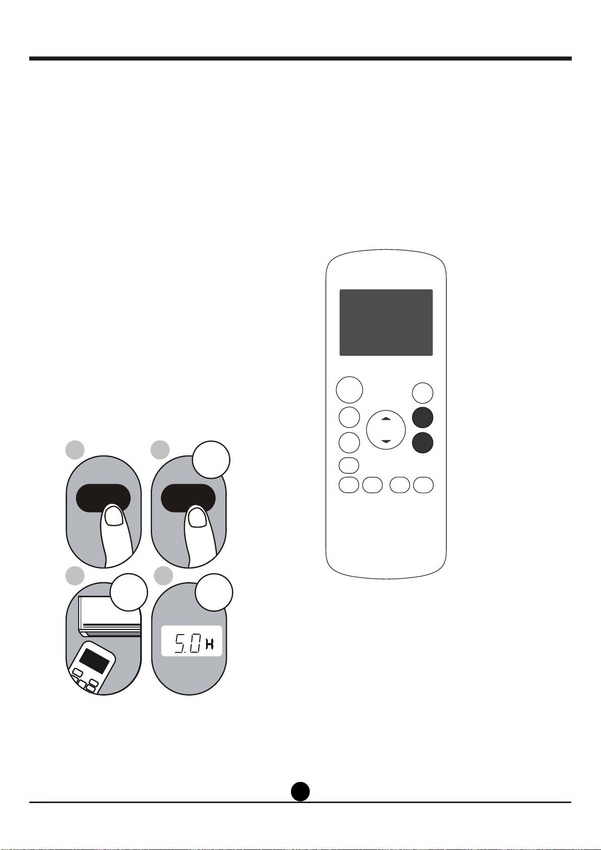
2.
Press the TIMER OFF button repeatedly
to set the time when you want the unit to
turn off.
3. Wait 2 seconds, then the TIMER OFF
function will be activated. The digital
display on your remote control will then
return to the temperature display.
Example: Setting unit to turn off after 5
hours.
TIMER OFF function
The TIMER OFF function allows you to
set a period of time after which the unit
will automatically turn off, such as when
you wake up.
1.
This number indicates the
amount of time after the current time
that you want the unit to turn off.
For example, if you set TIMER OFF for
2 hours, will appear on the
screen, and the unit will turn off after
2 hours.
Press the TIMER OFF button. By
default, the last time period that you
set and an "h" (indicating hours)will
appear on the display.
Note:
" 2.0h "
2sec
x10
ON/OFF
MODE
FAN
SHORT
CUT
TIMER ON
TIMER OF
F
TEMP
S
L
EEP
1sec
1
3
2
4
TIMER OFF
TIMER OFF
Continue to press
TIMER ON
or
TIMER OFF until
desired time is
reached.
ON/OFF
TEMP
SHORT
CUT
TIMER
ON
TIMER
OFF
MODE
FAN
SLEEP
LED
Timer on
FOLLOW
SWING
ION
ME
1111
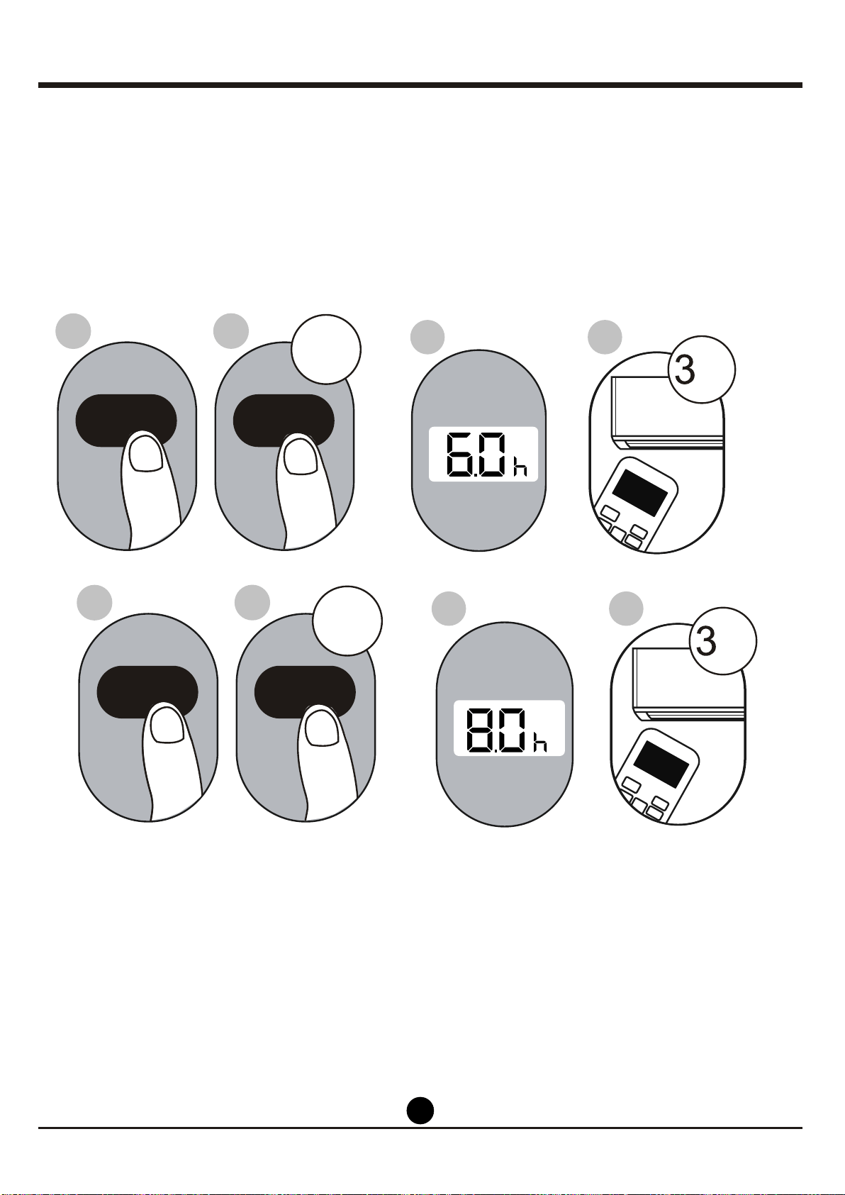
Setting both TIMER ON and TIMER OFF at the same time
Keep in mind that the time periods you set for both functions refer to hours after the
current time.
For example, say that the current time is 1:00 PM, and you want the unit
to turn on automatically at 7:00 PM. You want it to operate for 2 hours, then automa-
tically turn off at 9:00 PM.
Do the following:
ON/OFF
ON/OFF
MODE
MODE
SHORT
SHORT
CUT
CUT
TIMER ON
TIMER ON
TEMP
TEMP
sec
sec
4
8
3
7
X12
X16
2
6
1
5
TIMER ON
TIMER ON
TIMER OFF
TIMER OFF
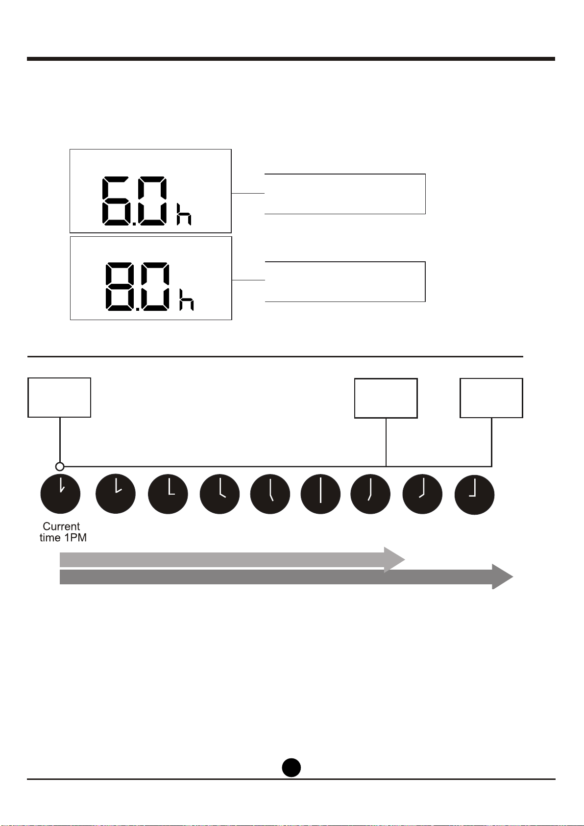
Example: Setting the unit to turn on after 6 hours, operate for 2 hours, then turn off
(see the figure below)
Your remote display
Timer is set To turn ON
6 hours from current time
Timer is set to turn OFF
8 hours from current time
2PM 3PM
4PM 5PM
6PM 7PM 8PM 9PM
Timer starts
Unit turns Unit turns
ON
OFF
6 hours later
8 hours later
Timer on
Timer off
1212
1313
The FOLLOW ME function enables the
remote control to measure the temper-
ature at its current location. When using
AUTO, COOL, or HEAT functions,
measuring ambient temperature from
the remote control (instead of from the
indoor unit itself) will enable the air
conditioner to optimize the temperature
around you and ensure maximum comfort.
1. Press FOLLOW ME button to activate
function. The remote control will send
temperature signal to the unit every
three minutes.
2. Press FOLLOW ME button again to
turn off this function.
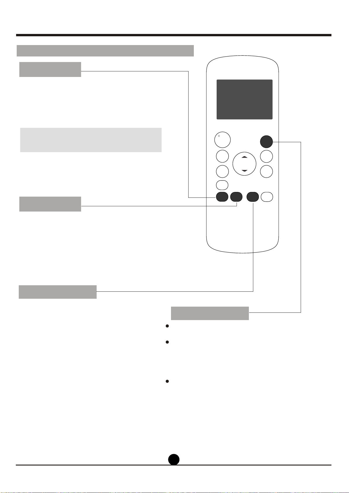
FOLLOW ME function
SHORTCUT function
SWING Function
The SLEEP function is used to decrease
energy use while you sleep (and don t need
the same temperature settings to stay
comfortable).
Note: The SLEEP function is not available
in FAN or DRY mode.
,
Used to restore the current settings or resume
previous settings.
Push this button when remote controller is on,
the system will automatically revert back to
the previous settings including operating mode,
setting temperature, fan speed level and sleep
feature (if activated).
If pushing more than 2 seconds, the system
will automatically restore the current operation
settings including operating mode, setting
temperature, fan speed level and sleep
feature(if activated ).
Used to stop or start louver movement and set
the desired up/down air flow direction. The louver
changes 6 degrees in angle for each press(some
models without). If keep pushing more than 2
seconds, the louver auto swing feature is activated.
How To Use The Advanced Functions
ON/OFF
TEMP
SHORT
CUT
TIMER
ON
TIMER
OFF
MODE
FAN
LED
ION
SLEEP
FOLLOW
SWING
ME
SLEEP Function
1414
NOTE:
-Buttons design is based on typical model and might be slightly different
from the actual one you purchased, the actual shape shall prevail.
-All the functions described are accomplished by the unit, if the unit has
no this feature, there is no corresponding operation happened when
press the relative button on the remote controller.
-When there are wide differences between Remote controller Illustration
and USERS MANUAL on function description, the description on USERS
MANUAL shall prevail.
-The device could comply with the local national regulations. In Canada,
it should comply with CAN ICES-3(B)/NMB-3(B). In USA, this device
complies with part 15 of the FCC Rules. Operation is subject to the
following two conditions: (1) This device may not cause harmful interfe-
rence, and (2) this device must accept any interference received,
including interference that may cause undesired operation.
-This equipment has been tested and found to comply with the limits for
a Class B digital device, pursuant to part 15 of the FCC Rules. These
limits are designed to provide reasonable protection against harmful
interference in a residential installation. This equipment generates, uses
and can radiate radio frequency energy and, if not installed and used in
accordance with the instructions, may cause harmful interference to radio
communications. However, there is no guarantee that interference will
not occur in a particular installation. If this equipment does cause harmful
interference to radio or television reception, which can be determined by
turning the equipment off and on, the user is encouraged to try to correct
the interference by one or more of the following measures:
Reorient or relocate the receiving antenna.
Increase the separation between the equipment and receiver.
Connect the equipment into an outlet on a circuit different from that to
which the receiver is connected.
Consult the dealer or an experienced radio/TV technician for help.
Changes or modifications not approved by the party responsible for
compliance could void suers authority to operate the equipment.


The design and specifications are subject to change without prior
notice for product improvement. Consult with the sales agency or
manufacturer for details.