Loading ...
Loading ...
Loading ...
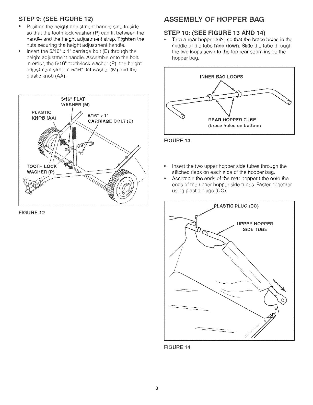
STEP 9: (SEE FIGURE 12)
® Position the height adjustment handle side to side
so that the tooth lock washer (P) can fit between the
handle and the height adjustment strap, Tighten the
nuts securing the height adjustment handle,
insert the 5/16" x 1" carriage bolt (E) through the
height adjustment handle, Assemble onto the bolt,
in order, the 5/16" tooth-lock washer (P), the height
adjustment strap, a 5/16" flat washer (M) and the
plastic knob (AA),
PLASTmC
KNOB (AA)
5116" FLAT
WASHER (M)
5/16" x 1"
CARRIAGE BOLT (E)
TOOTH LOCK
WASHER (P)
FIGURE 12
ASSEMBLY OF HOPPER BAG
STEP 10: (SEE FIGURE 13 AND 14)
Turn a rear hopper tube so that the brace holes in the
middle of the tube face down, Slide the tube through
the two loops sewn to the top rear seam inside the
hopper bag,
ruNNERBAG LOOPS
REAR HOPPER TUBE
(brace holes on bottom)
FIGURE 13
insert the two upper hopper side tubes through the
stitched flaps on each side of the hopper bag,
Assemble the ends of the rear hopper tube onto the
ends of the upper hopper side tubes, Fasten together
using plastic plugs (CC),
LASTmCPLUG (CO)
?-
UPPERHOPPER
j SmDETUBE
FIGURE 14
Loading ...
Loading ...
Loading ...