
Owners Manual - Lucid Air

Contents
Introduction......................................................................................................... 15
A Message From Lucid...............................................................................15
A Message From Lucid.......................................................................... 15
About This Manual.......................................................................................16
Using This Manual, Locating and Referencing Information... 16
Document Applicability......................................................................... 16
Illustrations................................................................................................... 16
Revisions and Modiications.................................................................16
Symbols Glossary for Important Information............................... 16
Trademarks................................................................................................. 16
Copyright......................................................................................................16
Information About This Vehicle............................................................. 17
Quality Control...........................................................................................17
Vehicle Modiications.............................................................................. 17
Body Repairs...............................................................................................17
Electric Vehicle Precautions.................................................................17
Personal Information and Data Sharing...........................................17
Data Sharing Permissions......................................................................18
Vehicle Overview.............................................................................................. 19
Exterior.............................................................................................................. 19
Exterior Overview.....................................................................................19
Interior...............................................................................................................20
Interior Overview......................................................................................20
Steering Wheel Controls....................................................................... 22
Glass Cockpit............................................................................................. 23
Pilot Panel....................................................................................................23
Smart Drawer............................................................................................. 24
Rear Center Console Display (RCCD)........................................... 24

Opening and Closing.......................................................................................25
Keyless Entry System.................................................................................. 25
Using the Key Fob....................................................................................25
Using the Valet Card............................................................................... 26
Replacing the Keyfob Battery..............................................................26
PIN to Drive................................................................................................. 27
Caring for the Key Fob........................................................................... 27
Replacement Key Fobs.......................................................................... 27
Type Approval...........................................................................................27
Doors................................................................................................................. 29
Opening Doors from the Outside..................................................... 29
Opening Doors from the Inside......................................................... 29
Door Warnings..........................................................................................30
Locking and Unlocking from Inside the Vehicle.........................30
Child Safety Locks................................................................................... 30
Automatic Locking and Unlocking...................................................30
Opening Interior Doors with No Power......................................... 30
Windows........................................................................................................... 31
Window Safety........................................................................................... 31
Opening and Closing Windows..........................................................31
Sunshades.................................................................................................... 31
Hood.................................................................................................................. 33
Hood Opening and Closing.................................................................33
Accessing the Front Cargo Area....................................................... 34
Hood Interior Emergency Release....................................................34
Trunk................................................................................................................. 35
Trunk Opening and Closing................................................................35
Accessing the Rear Cargo Area......................................................... 36
Trunk Interior Emergency Release...................................................36
Safety & Security...........................................................................................37
Shock & Tilt Alert.....................................................................................37

Seating & Safety Restraints...........................................................................38
Front Seats.......................................................................................................38
Adjusting the Front Seats..................................................................... 38
Correct Seating Position........................................................................38
Massage Feature....................................................................................... 39
Seat Heating and Ventilation............................................................... 39
Rear Seats........................................................................................................ 40
Rear Seat Folding.....................................................................................40
Rear Seat Pass-through......................................................................... 40
Rear Seat Heaters......................................................................................41
Head Restraints............................................................................................. 42
Correct Head Restraint Position........................................................42
Adjusting the Head Restraints............................................................ 42
Seat Belts..........................................................................................................44
Seat Belt Warnings...................................................................................44
Wearing Seat Belts...................................................................................44
Fastening the Seat Belt...........................................................................45
Seat belt reminders..................................................................................45
Using Seat Belts When Pregnant.......................................................46
Seat Belt Pre-tensioners.........................................................................46
Testing Seat Belts......................................................................................47
Child Safety Seats......................................................................................... 48
Guidelines for Seating Children.........................................................48
Choosing a Child Safety Seat.............................................................. 48
Seating Larger Children.........................................................................49
Installing Child Safety Seats................................................................. 49
Installing LATCH or ISOFIX Child Seats...................................... 50
Attaching Upper Tether Straps...........................................................51
Child Safety Seat Warnings..................................................................52
Airbags.............................................................................................................. 53
Location of Airbags and Airbag Sensors........................................53
Airbag Safety Information.....................................................................54

Airbag Safety Labels................................................................................54
How the Airbags Work.......................................................................... 54
Types of Airbags.......................................................................................55
Obstruction of Airbags...........................................................................56
Front Passenger Seat Occupant Classiication System
(OCS)........................................................................................................ 56
Eects of Airbag Inlation...................................................................... 58
Airbag SRS Warning Indicator........................................................... 59
Airbag Service Information.................................................................. 59
Driving & Operating........................................................................................60
Driver Information....................................................................................... 60
Vehicle Information and Alerts.......................................................... 60
Trip Information....................................................................................... 60
Pilot Panel.........................................................................................................61
Extending and Retracting the Pilot Panel....................................... 61
Instrument Cluster........................................................................................62
Instrument Cluster - Overview............................................................62
Warning Indicators.................................................................................. 63
High-Voltage Drive System Failure...................................................67
Charge and Power Meter...................................................................... 67
Battery State of Charge Indicator....................................................... 67
Starting and Powering O.........................................................................68
Starting.......................................................................................................... 68
Powering O...............................................................................................68
Steering Wheel.............................................................................................. 69
Adjusting the Steering Wheel Position........................................... 69
Steering Feel and Sensitivity................................................................69
Steering Wheel - Right Controls........................................................ 70
Horn................................................................................................................ 71
Drive Selector................................................................................................. 72
Selecting a Drive Mode.......................................................................... 72
Creep Mode................................................................................................ 72

Drive Modes....................................................................................................73
Drive Modes................................................................................................73
Limited Power Mode.............................................................................. 73
Mirrors............................................................................................................... 74
Adjusting the Exterior Side Mirror Position..................................74
Interior Rear View Mirror......................................................................74
Exterior Lights................................................................................................ 75
Exterior Lights Control...........................................................................75
High Beam Headlights............................................................................ 75
Rear Fog Light............................................................................................76
Turn Signals................................................................................................ 76
Hazard Warning Lights...........................................................................76
Interior Lights..................................................................................................78
Interior Lights..............................................................................................78
Ambient Lighting...................................................................................... 78
Wipers and Washers................................................................................... 79
Wipers........................................................................................................... 79
Washers........................................................................................................ 79
Brakes................................................................................................................80
Braking Systems....................................................................................... 80
Anti-Lock Braking System (ABS)......................................................80
Regenerative Braking...............................................................................81
Stop Mode................................................................................................... 81
Parking Brake............................................................................................. 82
Brake Pad Wear........................................................................................ 82
Lucid Stability Control............................................................................... 84
Lucid Stability Control........................................................................... 84
Getting Maximum Range.......................................................................... 85
Driving Tips to Maximize Range........................................................85
Heating, Ventilation Air Conditioning................................................. 86
Temperature Control............................................................................. 86
Defrost........................................................................................................... 87
Interior Equipment.......................................................................................88
Sun Visors................................................................................................... 88

Glove Box.................................................................................................... 89
Front Armrest and Storage Compartment................................... 89
Center Console Storage Compartment..........................................89
Rear Armrest and Storage Compartment..................................... 89
Cup Holders...............................................................................................90
Accessory Connections..............................................................................91
USB Connections......................................................................................91
Wireless Charging.....................................................................................91
12 Volt Power Socket.............................................................................. 92
Advanced Driver Assistance Systems (ADAS)................................... 93
About ADAS.................................................................................................. 93
ADAS Limitations.................................................................................... 93
ADAS Features......................................................................................... 93
ADAS Component Locations............................................................ 95
DreamDrive.....................................................................................................97
Steering Wheel DreamDrive Controls............................................ 97
DreamDrive Requirements..................................................................98
Adaptive Cruise Control....................................................................... 98
Highway Assist........................................................................................ 100
Traic Sign Recognition...................................................................... 102
Traic Drive-O Alert...........................................................................103
Distracted Driver Alert.........................................................................104
Drowsy Driver Alert.............................................................................. 104
Collision Protection................................................................................... 106
Forward Collision Warning............................................................... 106
Automatic Emergency Braking........................................................ 106
Cross Traic Protection.......................................................................108
Lane Departure Protection................................................................ 108
Blind Spot Warning...............................................................................109
Blind Spot Display.................................................................................. 110
Parking Experience......................................................................................111
Automatic Park In.................................................................................... 111

Automatic Park Out............................................................................... 113
Surround View Monitoring.................................................................115
Rear View Monitoring........................................................................... 116
Park Distance Warning......................................................................... 116
Park Comfort Braking............................................................................ 117
Infotainment....................................................................................................... 118
User Proiles...................................................................................................118
About User Proiles................................................................................ 118
Creating a User Proile.......................................................................... 118
Proile Settings.......................................................................................... 119
Face Unlock.............................................................................................. 120
Loading and Switching Proile Preferences.................................120
Removing Secondary User Proiles................................................120
Changing Display Settings................................................................... 121
Media and Audio........................................................................................ 122
Media Overview.......................................................................................122
Physical Media Controls...................................................................... 123
Searching Media Content....................................................................125
AM and FM Radio..................................................................................125
Logging into Media Applications..................................................... 126
Using Alexa Built-In................................................................................126
Playing Media from Devices............................................................... 127
Audio Settings.......................................................................................... 127
Maps and Navigation................................................................................. 128
Navigation Overview..............................................................................128
Navigating................................................................................................... 128
Adjusting the Map.................................................................................. 129
Predicting Energy Usage......................................................................129
Setting Home and Work Destinations........................................... 129
Map Updates and Oline Mode.......................................................130
Phone and Smart Devices........................................................................131
Bluetooth® Wireless Technology.....................................................131

Pairing a Bluetooth Device.................................................................. 131
Syncing Contacts and Messages....................................................... 131
Connecting and Disconnecting Bluetooth Enabled
Devices.....................................................................................................131
Editing Bluetooth Enabled Device Preferences.........................132
Using the Phone App............................................................................132
Making and Receiving Phone Calls.................................................132
In-Call Options.........................................................................................133
Using Messages........................................................................................133
Connecting the Vehicle to Wi-Fi®....................................................... 134
Add a New Wi-Fi Network................................................................. 134
Edit or Remove a Wi-Fi Network.................................................... 134
Wi-Fi Quick Access............................................................................... 134
HomeLink...................................................................................................... 135
What is HomeLink?............................................................................... 135
HomeLink FCC/ISED Advisory...................................................... 135
Programming HomeLink.....................................................................135
Using HomeLink®.................................................................................. 136
Renaming or Deleting a Program.................................................... 136
Vehicle Information....................................................................................138
Vehicle Identiication Number.......................................................... 138
Direct Access to the Owner's Manual............................................138
Alerts and Notiications........................................................................138
Software Updates........................................................................................139
Current Software Version................................................................... 139
Updating Software..................................................................................139
Viewing Release Notes.........................................................................140
High-Voltage Battery Pack & Charging..................................................141
Electric Vehicle Components.................................................................141
High-Voltage Components................................................................. 141
Battery Information.................................................................................... 143
About the Vehicle Batteries............................................................... 143

High Voltage Battery Pack Care....................................................... 143
Charging Instructions................................................................................ 144
Safety Checklist....................................................................................... 144
Lucid Mobile Charging Cable........................................................... 144
Charge Port Door...................................................................................144
Charging the Vehicle.............................................................................145
Disconnecting the Charging Cable..................................................145
Charging Status........................................................................................146
Setting a Charge Limit........................................................................... 147
Cold Weather Charging Considerations.......................................147
Maintenance......................................................................................................148
Maintenance Requirements................................................................... 148
Your Responsibility............................................................................... 148
Scheduled Maintenance......................................................................148
Fluid Replacement.................................................................................148
Owner Maintenance..............................................................................148
Electrical and High Voltage Safety.................................................. 148
Maintenance Schedule.........................................................................150
Multi-Point Inspection........................................................................... 151
Maintenance Panel..................................................................................... 152
Under Hood Rear Apron....................................................................152
Fluid Reservoirs...........................................................................................153
Checking Brake Fluid........................................................................... 153
Checking Washer Fluid....................................................................... 154
Wiper Blades and Washer Jets............................................................. 155
Checking the Wiper Blades................................................................155
Replacing Wiper Blades...................................................................... 155
Cleaning Washer Jets............................................................................155
Cabin Air Filter.............................................................................................157
Replacing the Cabin Air Filters......................................................... 157
Vehicle Care..................................................................................................158
Cleaning the Exterior.............................................................................158

Polishing, Paint, and Body Repairs................................................. 159
Using a Car Cover.................................................................................. 160
Cleaning the Interior..............................................................................160
Floor Mats..................................................................................................162
Electrical..........................................................................................................163
12V Batteries............................................................................................. 163
Light Source Replacement................................................................. 163
Fuse Box Locations............................................................................... 163
Replacing a Fuse..................................................................................... 163
Front Fuse Box........................................................................................ 165
Cabin Fuse Box....................................................................................... 167
Rear Fuse Box..........................................................................................169
Parts and Accessories................................................................................ 171
Parts, Accessories, and Modiications.............................................171
Body Repairs............................................................................................. 171
Vehicle Lifting Points................................................................................. 172
Lifting the Vehicle................................................................................... 172
Tire & Wheels...................................................................................................173
Tire Information...........................................................................................173
Understanding Tire Markings............................................................173
International Tire Approval Marks..................................................176
Uniform Tire Quality Grading........................................................... 176
Tire and Loading Information Label...............................................177
Tire Care and Maintenance.................................................................... 178
Inspecting and Maintaining Tires..................................................... 178
Maintaining Tire Pressures................................................................. 179
Replacing Tires and Wheels..............................................................180
Seasonal Tire Types...............................................................................181
Driving in Low Temperatures........................................................... 182
Tire Traction Devices........................................................................... 182
Tire Pressure Monitoring System........................................................ 183
Tire Pressure Monitoring System (TPMS)..................................183

Vehicle Loading...........................................................................................185
Loading the Vehicle...............................................................................185
Steps for Determining Correct Load Limit..................................185
Technical Data..................................................................................................187
Vehicle Identiication................................................................................. 187
Vehicle Identiication Number.......................................................... 187
Vehicle Certiication Label..................................................................187
Vehicle Dimensions and Weights........................................................188
Exterior Dimensions..............................................................................188
Vehicle Weights.......................................................................................189
Wheels and Tires........................................................................................190
Wheel and Tire Speciications..........................................................190
Tire Pressures........................................................................................... 191
Vehicle Sub-Systems.................................................................................192
Steering....................................................................................................... 192
Brakes.......................................................................................................... 193
Front Suspension................................................................................... 194
Rear Suspension..................................................................................... 195
Motors......................................................................................................... 196
Transmission............................................................................................ 196
12V Batteries............................................................................................. 196
High-Voltage Battery............................................................................. 196
Roadside Assistance & Emergency Information............................... 197
Roadside Assistance.................................................................................. 197
Contacting Roadside Assistance...................................................... 197
Instructions for Transporters................................................................. 198
Transporting the Vehicle.....................................................................198
Preparing the Vehicle for Transportation....................................198
Pulling the Vehicle onto a Trailer or Transporter.................... 199
Securing the Vehicle for Transportation.....................................200
Disabling the Power System...................................................................201

Safety Precautions..................................................................................201
Emergency Responder Cut Loop................................................... 201
Vehicle Fire...................................................................................................202
Fireighting................................................................................................ 202
Consumer Information.................................................................................203
New Vehicle Limited Warranty............................................................203
Message to Customers.........................................................................203
Who is the Warrantor?........................................................................ 203
Who May Use This Limited Warranty?........................................203
What Does This Limited Warranty Cover? ...............................203
New Vehicle Limited Warranty....................................................... 204
Powertrain Limited Warranty...........................................................204
Battery Limited Warranty...................................................................204
Corrosion Perforation Limited Warranty....................................205
Supplemental Restraint System (SRS) Limited Warranty... 205
What Does This Limited Warranty Not Cover?....................... 205
What Will Cause the Warranty to Be Voided?..........................207
What to do if you need Roadside Assistance?.......................... 207
What is the Coverage Period?.......................................................... 207
What Are Your Remedies?................................................................207
Limitations on Liability........................................................................ 208
Dispute Resolution................................................................................208
Customer Care.............................................................................................210
Contacting Lucid Motors.................................................................... 210
Reporting Safety Defects.......................................................................... 211
United States..............................................................................................211
Canada......................................................................................................... 211
Disclaimers.....................................................................................................212
California Proposition 65....................................................................212
California Perchlorate Advisory....................................................... 212
Vehicle Telematics................................................................................. 212
Vehicle Recycling........................................................................................213

High-Voltage Battery Recycling Process.......................................213
FCC and FDA Compliance....................................................................214
FCC Certiication.................................................................................... 214
Index.....................................................................................................................220

A Message From Lucid
A Message From Lucid
Thanks for choosing Lucid. We’re honored to
have you aboard.
Lucid Air was designed and engineered with
a devout dedication to detail, every aspect
carefully considered. We hope you cherish this
vehicle as much as we did in developing it.
This Manual helps you get acquainted with your
Lucid Air, and includes important information
on how to operate, maintain, and get the most
out of your ownership experience.
Congratulations on your purchase, and
welcome to luxury electric.
Introduction 15

About This Manual
Using This Manual, Locating and Referencing Information
This Owner’s Manual contains information to
help you configure, maintain, and enjoy your
Lucid Air. We advise you to take some time to
familiarize yourself with it before driving.
Failure to follow the manual’s instructions and
warnings can result in vehicle damage, severe
personal injury or death to you and others, and
voiding the New Vehicle Limited Warranty.
To quickly find a topic, please refer to the index.
Note: References to the vehicle's left or right
side assume you are seated in the car facing
forward.
Document Applicability
This Manual applies to all Lucid Air vehicles.
Lucid regularly updates this manual. The latest
version is accessible via the Pilot Panel and
on the Lucid website. Internet connection is
required to download the most recent version
of the manual.
Illustrations
The Owner's Manual provides illustrations
to locate components or features described
in the accompanying text. Depending on
vehicle specification, software version, region
of purchase, and specific settings, your vehicle
may appear slightly different. However, the
essential information in the illustrations is
correct.
Revisions and Modifications
Continuous improvement is a goal at Lucid, and
we reserve the right to make changes at any
time, without notice and obligation.
Symbols Glossary for Important Information
The Owner’s Manual uses the following
symbols for important information:
WARNING: Indicates a hazard which, if
not avoided, or instruction which, if not
followed, could result in severe injury or
death.
CAUTION: Indicates a hazard which, if
not avoided, or instruction which, if not
followed, could result in damage to your
vehicle.
Environmental: Indicates an instruction to
observe to avoid unnecessary damage to the
environment.
Trademarks
Lucid, the Lucid logo, Air, the Air logo, Dream
Edition, DreamDrive, Wunderbox, Surreal
Sound, and Pure Spec logo are trademarks
of Lucid USA Inc, its subsidiaries, and/or its
affiliates.
The Bluetooth(R) word mark and logos are
registered trademarks owned by Bluetooth SIG,
Inc. and any use of such marks by Lucid is
under license.
All other trademarks contained in this
document are the property of their respective
owners, and their use herein does not imply
sponsorship or endorsement of their products
or services. The unauthorized use of any
trademark displayed in this document or on the
vehicle is strictly prohibited.
Copyright
©2021 Lucid USA, Inc. All rights reserved.
The information presented is current at the
time of publication and subject to copyright
and intellectual property rights of Lucid USA,
Inc. and its subsidiaries and/or affiliates. This
document may not be reproduced, archived, or
transmitted in any form or by any means, nor
modified or replicated to other sites, without
the prior written permission of Lucid USA, Inc.
Introduction 16
Information About This Vehicle
Quality Control
You may notice miles/kilometers on the
odometer when you take delivery of your
vehicle. The mileage is a result of the
comprehensive process used to ensure the
quality of your car.
Our quality control process includes extensive
inspections during and after production. The
final inspection takes place at the delivery
center and consists of a road test conducted
by a trained Lucid technician.
Vehicle Modifications
WARNING: Lucid does not recommend
installing non-approved parts and
accessories or performing non-
approved vehicle modifications. Doing
so can negatively affect your
vehicle’s performance and the safety
of its occupants. Non-approved
modifications may lead to invalidation
of your warranty.
WARNING: Lucid is not responsible for
death, injury, or damage that occurs
as the result of using or installing
non-approved parts or accessories, or
making non-approved modifications.
Note: If you have a disability that requires
modifying the vehicle, contact Lucid before
making any modifications.
Body Repairs
If you damage the vehicle in a collision,
make sure a Lucid-approved Service Center
repairs your car using only genuine Lucid
parts. Contact Lucid Customer Service -
1-888-LUCID. For more information, see Body
Repairs on page 171.
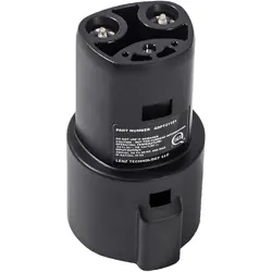
Electric Vehicle Precautions
WARNING: Your Lucid Air is a 100%
electric vehicle, utilizing high-voltage
AC and DC systems as well as a
12-volt system. The AC and DC high-
voltage systems can cause personal
injury, severe burns, electric shock, and
even death unless you take appropriate
precautions.
You will find the above label affixed to a
number of the high-voltage components found
on your vehicle to alert you to any possible
risks. Always observe and obey the instructions
on labels attached to components on the car;
they are there for your safety.
WARNING: Do not touch or attempt
to remove or replace any high-voltage
(HV) parts, wiring, or connectors. The
orange outer sleeving identifies the
high-voltage wiring and connectors.
WARNING: If the vehicle is involved
in an accident, do not touch any
high-voltage wiring or the components
connected to the wiring.
WARNING: Should a vehicle fire occur,
immediately evacuate the vehicle and
contact your local fire emergency
responders, as they possess the proper
training and equipment to extinguish
electric vehicle fires safely.
WARNING: The vehicle contains a
sealed Li-ion high-voltage battery.
Improperly disposing of the Li-ion
can risk personal injury, severe
burns, electrical shock, death, and
environmental damage.
Personal Information and Data Sharing
For information on how Lucid uses and protects
your personal information, visit our website at
www.lucidmotors.com/legal
Introduction 17

Data Sharing Permissions
You can disable data sharing from the Pilot
Panel by touching Settings > Connectivity >
Data Sharing Permissions. From here you can
tole data sharing settings.
Please note that disabling data sharing also
disables the following features:
- Signing in and out of your user profile
- Saving and restoring user profiles and
preferences to the cloud
- Resetting user PINs
- Mobile app interactions
Note: When data sharing with Lucid is disabled,
third-party apps still receive and transmit data
as needed by those third party terms of use.
Lucid may also still receive data and personal
information regarding you and your vehicle from
third parties.
Introduction 18

Exterior
Exterior Overview
1. Hood, see Hood Opening and Closing on page 33
2. Exterior side mirror, see Adjusting the Exterior Side Mirror Position on page 74
3. Front multifunction camera
4. Pillar camera
5. Rear view camera, see Rear View Monitoring on page 116
6. Tires and wheels, see Inspecting and Maintaining Tires on page 178
7. Exterior door handle, see Opening Doors from the Outside on page 29
8. Surround View Monitoring cameras, see Blind Spot Display on page 110
9. Trunk, see Trunk Opening and Closing on page 35
10. Charge port door, see Charge Port Door on page 144
11. Recovery eye attachment point, see Pulling the Vehicle onto a Trailer or Transporter on page 199
12. Headlights, see Exterior Lights Control on page 75
Note: For detailed camera locations, see
ADAS Component Locations on page 95.
Vehicle Overview 19
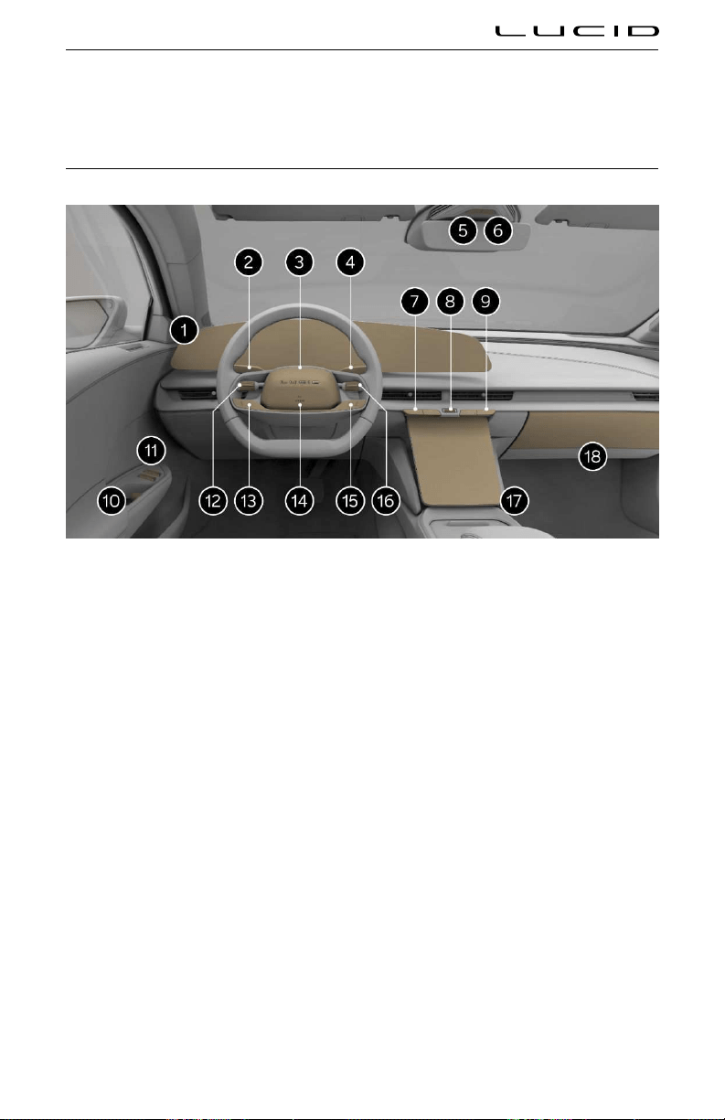
Interior
Interior Overview
1. Glass Cockpit, see Glass Cockpit on page 23
2. Left control stalk:
○ Washers, see Washers on page 79
○ Turn Signals, see
Turn Signals on page 76
○ High Beams, see
High Beam Headlights on page 75
3. Driver camera (behind the steering wheel), see
Face Unlock on page 120
4. Gear and parking brake selector, see Selecting a Drive Mode on page 72
5. Hazard warning lights button, see Hazard Warning Lights on page 76
6. Interior light, see Interior Lights on page 78
7. Driver temperature controls, see Temperature Control on page 86
8. Volume control, see Physical Media Controls on page 123
9. Passenger temperature controls, see
Temperature Control on page 86
10. Interior door handle, see Opening Doors from the Inside on page 29
11. Window switches, see Opening and Closing Windows on page 31
12. Left tole switch, see Steering Wheel DreamDrive Controls on page 97
Vehicle Overview 20

13. DreamDrive controls, see Steering Wheel DreamDrive Controls on page 97
14. Horn, see Horn on page 71
15. Media controls, see Steering wheel media controls on page 123
16. Right tole switch, see Steering wheel media controls on page 123
17. Pilot panel, see Pilot Panel on page 61
18. Glove box, see Glove Box
Vehicle Overview 21

Steering Wheel Controls
1. Left tole switch, see Steering Wheel DreamDrive Controls on page 97
2. DreamDrive button, see Steering Wheel DreamDrive Controls on page 97
3. Following distance button, see Steering Wheel DreamDrive Controls on page 97
4. Cancel button, see Steering Wheel DreamDrive Controls on page 97
5. Right tole switch, see Steering wheel media controls on page 123
6. Previous button, see Steering wheel media controls on page 123
7. Next button, see Steering wheel media controls on page 123
8. Voice Assistant button, see Steering wheel media controls on page 123
Vehicle Overview 22
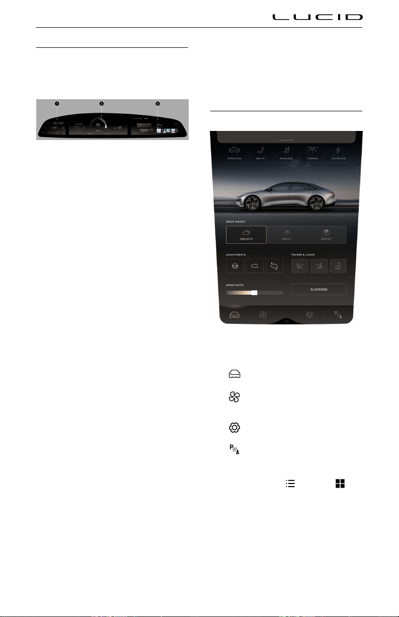
Glass Cockpit
The 34-inch (86 cm) Glass Cockpit is
ergonomically contoured to the driver, giving
you easy access to controls without being
distracted.
1. Left Cockpit Panel: The functions on this
touchscreen are available at all times:
○ Charge port door control, see Charge
Port Door on page 144
○ Door locks, see Opening Doors from
the Inside on page 29
○ Window locks, see Opening and
Closing Windows on page 31
○ Front and rear windshield defrost,
see Defrost on page 87
○ Exterior lighting controls, see Exterior
Lights Control on page 75
○ Wiper controls, see Wipers on page
79
2. Instrument Cluster: This panel displays
the centralized Instrument Cluster,
with system messages and information
displayed to the left and right. Any
warning indicators appear here. See
Warning Indicators on page 63.
3. Right Cockpit Panel: This touchscreen
gives you access to the following:
○ Media and audio, see Media and
Audio on page 122
○ Maps and navigation, see Maps and
Navigation on page 128
○ Communication, see Phone and
Smart Devices on page 131
○ User Profiles, see
User Profiles on
page 118
○ HomeLink® controls, see HomeLink
on page 135
○ Bluetooth® controls, see
Connecting
and Disconnecting Bluetooth
Enabled Devices on page 131
○ Wi-Fi® controls, see Wi-Fi Quick
Access on page 134
Pilot Panel
The icons along the bottom of the Pilot Panel
touchscreen allow you to access:
-
Vehicle controls
- Climate controls, see Temperature
Control on page 86
-
Settings menu
- Parking controls, see Parking
Experience on page 111
Note: In some menus on the Pilot Panel, you
can press the icons for
list view or tile
view to tole between display options.
Note: The Pilot Panel can be retracted to
access the storage space behind it. See
Extending and Retracting the Pilot Panel on
page 61.
Vehicle Overview 23

Smart Drawer
Some applications display in the smart drawer
window on the right Cockpit Panel, allowing you
to browse the contents. The Pilot Panel view of
the smart drawer shows additional details for
lists and libraries.
WARNING: This content is intended to
minimize driver distraction to facilitate
safe driver behavior. It is recommended
that the driver maintains vision of the
road at all times during normal driving
maneuvers. Distracted driving can lead
to serious injury or death.
To open the smart drawer in the Pilot Panel,
press the bar at the top of the touchscreen; in
the right Cockpit Panel, press the bar at the
bottom of the touchscreen. Swipe the smart
drawer up or down to slide it between screens.
If the smart drawer collapses due to timeout on
either screen, touch the bar to expand it again.
The < arrow in the upper left corner of a menu
title returns you to the previous screen.
Rear Center Console Display (RCCD)
The Rear Center Console Display (RCCD) is
located at the back of the center console
and allows rear seat passengers to control the
climate and the sunshade settings.
The RCCD provides the following options for
rear seat passengers:
-
Sunshade - Deploys and retracts the
Rear Sunshade, see Sunshades on page
31.
-
Climate - Controls for temperature,
fan speed, and seat heating in the rear
seats, see Rear Seat Heaters on page 41.
Note: You can lock access to the Rear Center
Console Display (RCCD) by navigating to
Settings > Pilot Displays on the Pilot Panel.
Vehicle Overview 24

Keyless Entry System
Using the Key Fob
Your vehicle includes two keyless entry
systems: a key fob and a valet card.
WARNING: The keyless entry system
uses low-frequency radio transmissions
that might interfere with implanted
medical devices. To avoid any
possibility of interference, keep such
medical devices away from any
transmitters.
WARNING: To prevent other occupants'
accidental operation of the vehicle's
systems, do not leave a key fob in an
unattended vehicle.
CAUTION: To ensure your vehicle is
left in a secure state, remove all key
fobs from the car before leaving it
unattended.
Key fob range
The key fob communicates with receivers in
the vehicle via Bluetooth® Low Energy (LE) and
low-frequency radio communication. While it is
not necessary to point your key fob at the car, it
must be within operating range to work.
Note: The key fob operating range varies,
depending upon environmental factors. Nearby
radio transmitters (e.g., amateur or CB radios,
radio or television stations, airports) may
interfere with communications between the key
fob and the vehicle. In cases of interference,
it may be necessary to move closer to the car
than usual to operate the key fob.
You can operate the key fob manually once it is
detected or is closer to the vehicle.
While carrying a key fob, all doors will
automatically unlock and present their handles
when approaching your vehicle.
When leaving your vehicle while carrying a key
fob, all doors will automatically lock, and any
presented door handles will retract.
Key fob operation
As you approach the vehicle, the key fob should
be within range.
Note: The key fob button is located on the
center of the top surface, in the middle of the
LUCID logo.
Once within range, the key fob operates as
follows:
- Press once to lock all doors, trunk, and
front trunk.
- Press twice to unlock all doors, trunk, and
front trunk.
- Press and hold the button to open or
close the front trunk.
- Press the button four times for the panic
alarm to trier. To cancel the panic
alarm, press the button four times again
or twice to unlock it.
Key fob troubleshooting
If the key fob does not respond when pressed:
- Try operating the key fob as closely
to your vehicle as possible. Other
radio equipment operating on a similar
frequency may interfere with the signals
from your key fob.
- The key fob battery may need replacing.
See Replacing the Key Fob Battery. If the
key fob battery is depleted, you can still
unlock the vehicle by holding it near the
driver's side center pillar (similar to the
valet card).
If you cannot unlock your vehicle with the key
fob, use the mobile app or Valet Card. See
Opening and Closing 25

Using the Valet Card. Contact Lucid Customer
Care if the problem persists.
Using the Valet Card
Use the Lucid Valet Card within close range of
the vehicle only and as a backup method for
vehicle entry. You might use or lend the Valet
card when:
- Using a valet parking service
- Leaving your vehicle to be serviced or
repaired at a Lucid Service Center
- Experiencing key fob issues (e.g.,
misplaced or low battery)
Hold the Valet card just above the driver's side
center pillar camera to lock or unlock the doors.
Note: To drive the vehicle using only the valet
card, you must enter the pin associated with
the current user profile when shifting out of
Park.
Replacing the Keyfob Battery
WARNING: The key fobs supplied with
your vehicle contain a coin/button-type
battery. These batteries contain toxic
and corrosive substances. Batteries
are a chemical burn hazard and
should never be ingested. Battery, when
swallowed, can cause severe internal
burns and may even lead to death.
- Keep new and used batteries out of
the reach of children.
- If you think batteries may have been
swallowed, seek immediate medical
attention.
WARNING: If the cover for the key fob
will not close securely, stop using the
key fob and keep it out of the reach
of children. Contact a Lucid Service
Center for a replacement key fob.
WARNING: There is a risk of explosion
if an incorrect battery is installed. Only
install a battery that is identical to the
battery specified in this manual.
The key fob battery is type CR2032 and
will need occasional replacement. The vehicle
alerts you with a ‘Keyfob Battery Low’ message
on the instrument cluster.
Note: Replace a low key fob battery as soon as
possible to avoid complications with the vehicle
systems.
To replace the key fob battery:
1. Remove the battery cover.
2. Remove the old battery.
3. Avoid touching the flat surfaces of the
new battery if possible, as fingermarks
can reduce battery life.
4. Wipe the battery clean before installation.
5. Fit the battery with the “
+” side facing
upwards.
Opening and Closing 26

6. Replace the battery cover.
Environmental: Used batteries must be
disposed of correctly, as they contain harmful
substances. Please refer to local regulations.
Dead Key fob Battery
Even when the key fob battery has died, it
is possible to access the car. Press the door
handle to lock or unlock the car, then hold
the key fob against the driver's side center
pillar under the camera area to perform a lock/
unlock action.
PIN to Drive
When accessing the vehicle with a dead key
fob or valet card, drivers are prompted for the
PIN associated with their driver profile. After
pressing the brake pedal, drivers will see the
following in the Pilot Panel.
After entering a valid PIN, drivers can operate
the vehicle until the driver's door opens again,
resetting authentication.
After 21 unsuccessful attempts, the driver
cannot enter the PIN code for a time-out period
of 2 hours. For instructions about resetting the
PIN, please see PIN Reset.
Caring for the Key Fob
CAUTION: To protect the electronic
circuitry inside, do not expose the key
fob to:
- Impacts
- Liquids
- High temperatures (including
prolonged sunlight exposure)
- Waxes, solvents, or abrasive cleaners
Replacement Key Fobs
If you lose a key fob, contact a Lucid Service
Center to obtain a replacement.
If ordering a new key fob, you must bring
all available key fobs and Valet cards for
the vehicle to the Lucid Service Center to
reprogram the system.
Type Approval
United States
This device complies with Part 15 of the FCC
Rules.
Operation is subject to the following two
conditions:
1. This device may not cause harmful
interference, and
2. This device must accept any interference
received, including interference that may
cause undesired operation.
This equipment complies with FCC radiation
exposure limits set forth for an uncontrolled
environment. End-users must follow the
specific operating instructions for satisfying RF
exposure compliance. This transmitter must not
be co-located or operating in conjunction with
any other antenna or transmitter.
Changes or modifications not expressly
approved by the party responsible for
compliance could void the user's authority to
operate the equipment.
Opening and Closing 27

Canada
This device complies with Industry Canada’s
license-exempt RSS standards. Operation is
subject to the following two conditions:
1. This device may not cause interference,
and
2. This device must accept any interference,
including interference that may cause
undesired operation of the device.
Opening and Closing 28

Doors
Opening Doors from the Outside
Opening doors
The door handles will extend when:
- A valid key fob is detected next to the
vehicle.
- A valid key fob or valet card is detected
next to the vehicle on the left driver's
side center pillar, and the door handle is
pressed.
- The key fob is pressed twice to unlock the
doors. See Using the Key Fob.
- The mobile app is used to unlock the
doors.
Once a handle extends, pull up on it to open
that door.
Note: If a door handle is not opened within
two minutes of presenting, it will retract. Other
opening methods discussed in this section can
be used to extend it again.
Note: If there is a collision, all exterior door
handles will present if there is still available
power and the door units are not damaged.
Closing doors
The door handles retract when:
- The vehicle locks itself upon the user
with the keyfob(s) walking away from the
vehicle.
- A valid key fob or valet card is detected
within 2 inches (5 cm) of the sensor on
the left driver's side center pillar, and the
door handle is pressed.
- The key fob is pressed once to lock the
doors.
- The mobile app is used to lock all doors.
To close a door manually, push it until it is
almost closed; you will feel the power cinch
motor take over. The door will then close
automatically.
Opening Doors from the Inside
Pull the release handle mechanism (switch)
highlighted to open a door.
If a door is locked, pull and release the Release
Handle Mechanism (switch) once to unlock the
door.
To open the door, pull and release the Release
Handle Mechanism (switch) a second time.
If there is a power loss to the door, pull the
Release Handle Mechanism (manual) to full
travel once to open. Rear doors will not open
when child locks are engaged.
Note: To prevent children from using the
interior handles to open the rear doors, see
Child Safety Locks.
Note: Electric actuators (unlocking and
opening) using the Release Handle Mechanism
(switch) are disabled when the vehicle is in
motion. Release Handle Mechanism manual
release is functional on the Front Doors and
Rear Doors when the Child Lock function is not
engaged.
Opening and Closing 29
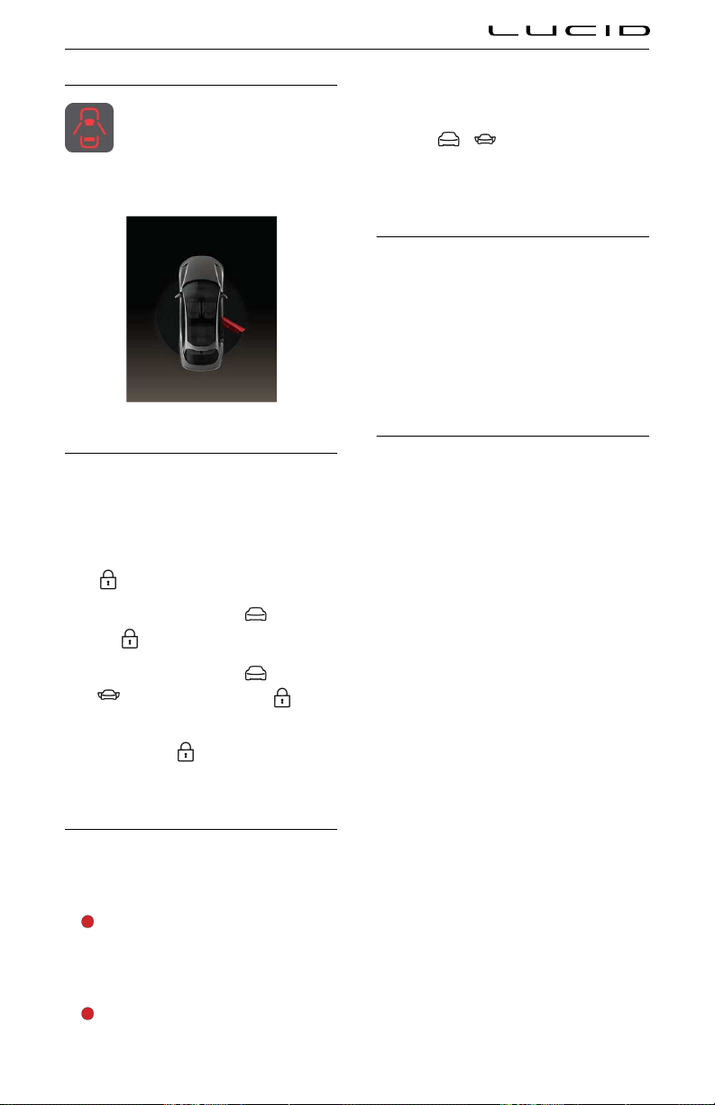
Door Warnings
Whenever a door is open while the
vehicle is in D (Drive) or R (Reverse),
the red Open Door warning indicator
appears on the Instrument Cluster,
and open doors are displayed as shown.
Locking and Unlocking from Inside the Vehicle
The doors and trunk can be locked and
unlocked from inside the vehicle using the
touch screens on the left Cockpit Panel or the
Pilot Panel. To lock or unlock all the doors:
- On the left Cockpit Panel, press the
lock/unlock icon.
- On the Pilot Panel, select
and press
the
lock/unlock icon.
- On the Pilot Panel, select
>
OPENINGS and press the lock/
unlock icon.
When pressed, the
icon will change to
a locked or unlocked symbol, indicating the
current state of the door locks.
Child Safety Locks
Your vehicle has child safety locks on both
rear doors. When active, this system prevents
occupants from opening rear doors using the
interior door handles.
WARNING: Child safety locks should be
activated whenever children are seated
in the back seats for their safety. There
is a risk of severe injury or death if a
child operates the back doors.
WARNING: Never leave children
unsupervised in any car.
Note: Exterior door handles will still operate
according to the vehicle's lock status.
To tole child safety locks, use the Pilot Panel
and touch
> OPENINGS, and then
touch the CHILD LOCK button. The CHILD
LOCK button illuminates when child safety
locks are activated.
Automatic Locking and Unlocking
Once the vehicle starts moving, all doors
automatically lock. The doors will remain
locked when the vehicle is in Park. (You can
choose to activate auto-unlock when shifting
into Park under Settings.)
If the airbags deploy, all doors will
automatically unlock but remain latched. See
E cts of Airbag Inflation.
Opening Interior Doors with No Power
If the vehicle loses power, you can open every
door using the interior door handles.
To open from inside, pull the interior handle to
the second detent for the manual door latch to
release.
Note: Child safety locks will be unavailable
in the event of a power loss, even if enabled
before the vehicle lost power (see Child Safety
Locks).
Opening and Closing 30

Windows
Window Safety
WARNING: Although your car is
equipped with obstacle detection on
all four windows, children, other
passengers, or objects can still be
trapped by moving windows. Use
caution when operating the windows.
- Do not allow children to play with
the window switches.
- Never stick objects or body parts
through an open window.
WARNING: On hot days, the
temperature in the vehicle interior can
rise very quickly. Exposure to these
high temperatures for even a short
time can cause a heat-related injury or
death. Small children and animals are
particularly at risk and should never be
left unattended in a vehicle.
Opening and Closing Windows
The power windows operate only when the
vehicle is powered on.
The driver’s door window switches control all
vehicle windows. Pull up or press down on a
switch to raise or lower the associated window.
Each passenger door contains a window switch
for its associated window.
- To automatically raise or lower a window
fully, push or pull the switch past the
resistance point and then release. Push or
pull the switch again to stop.
- To partially raise or lower a window,
gently push or pull the switch up to
the resistance point. Release when the
window is at the desired position.
Note: The windows will automatically stop
closing and reverse if an obstruction is
detected.
Inhibiting rear window operation
WARNING: Window locks should be
activated for children's safety. There is
a risk of severe injury or death if a child
operates the rear windows while seated
in the back seats.
WARNING: Never leave children
unsupervised in a vehicle.
You can operate the rear windows using the
switches on the rear doors when the window
lock is not activated.
The window lock feature in the left Cockpit
Panel or the Pilot Panel prevents passengers
from operating the rear window switches.
- To tole this feature, touch
>
DOORS and press WINDOW LOCK on
the Pilot Panel.
- Alternately, touch the
window lock
icon on the Left Cockpit Panel.
The WINDOW LOCK button illuminates when
active.
Sunshades
Some Lucid Air models are equipped with
power sunshades in the rear window and both
rear passenger windows. Raising the power
sunshades in sunny weather conditions can
reduce glare and help regulate the internal
vehicle temperature.
Side window sunshades
Window switches in the rear doors also operate
the side window sunshades. See
Opening and
Closing Windows.
Opening and Closing 31

Raise a sunshade by continuing to hold the
window UP button after the window is fully
raised.
Rear window sunshade
There are two way to operate the rear window
sunshade:
- On the Rear Center Console Display
home screen, select
SUNSHADE, and
touch EXTEND or STOW.
- From the Pilot Panel, select
>
OPENINGS, and touch the
sunshade icon to raise or lower the
sunshade.
Opening and Closing 32
Hood
Hood Opening and Closing
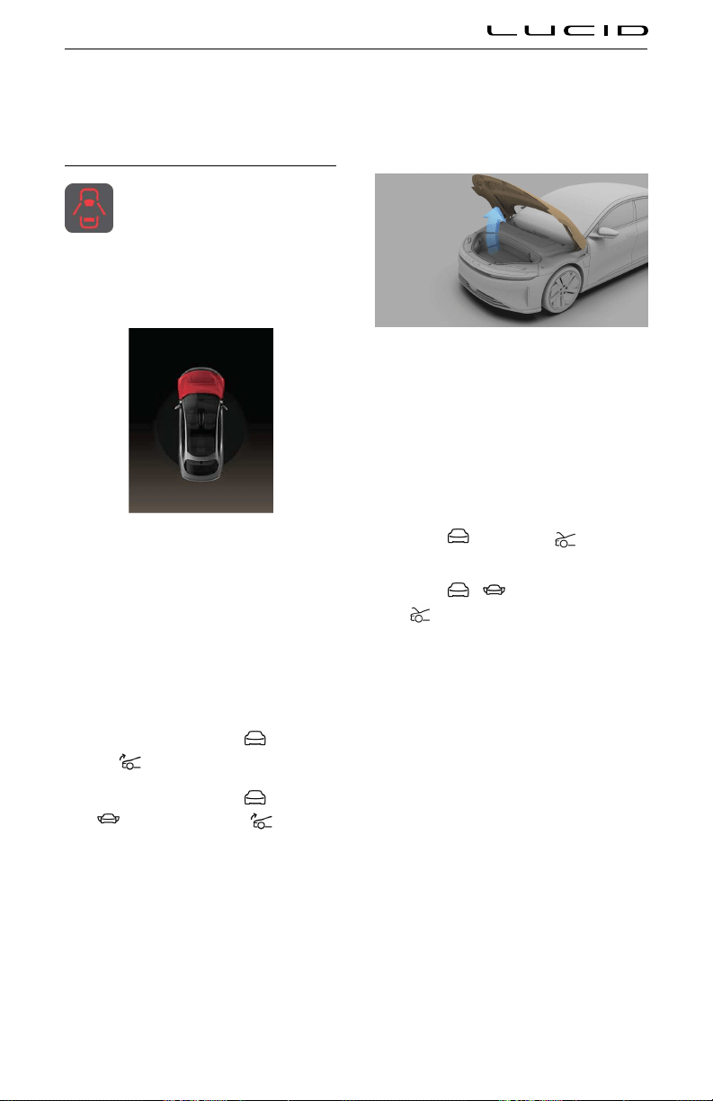
In the case of an unlatched hood,
the red Door Open warning indicator
appears on the Instrument Cluster. If
this occurs, Lucid recommends you
stop the vehicle in a safe location and place
the vehicle in P (Park). Then check if the hood
is correctly closed.
If the vehicle is in D (Drive) or R (Reverse) and
the hood is unlatched, it will be highlighted red.
Opening the hood
Note: All electrical unlatching of the hood is
disabled when the vehicle is in motion.
To electronically open and close the hood:
- Use the Lucid mobile app.
- On the Pilot Panel, select and press
the
hood opening icon.
- On the Pilot Panel, select
>
DOORS and press the hood
opening icon.
- Press and hold the key fob within 6.5 feet
(2 m) of the front trunk.
Once you have successfully unlatched the
hood, you may raise it. The hood has two gas
struts to aid in opening and to hold it in the
open position.
Note: In frigid temperatures, you may find that
the gas struts do not hold the hood open as
firmly as they do in warmer temperatures.
Closing the hood automatically
To close the hood using the power-assist
system:
- Use the Lucid mobile app.
- Select and press the hood close
icon on the Pilot Panel.
- Select
> DOORS and press the
hood close icon on the Pilot Panel.
- Press and release the close button on the
front edge of the frunk.
Automatic movement stop
If anything obstructs the hood to prevent it
from opening or closing, it will stop moving.
Note: The Instrument Cluster alerts you if the
hood stops automatically.
If the hood stops due to an obstruction, remove
it and try to open or close again. If it cannot be
opened or closed a second time, try to operate
the hood manually.
Closing the hood manually
Note: Some models may come equipped with
Power Opening and Closing Hood systems.
Opening and Closing 33

WARNING: Always check the area
around the hood for obstructions (such
as people or objects) before closing the
hood. Failure to do so could result in
serious injury to a person or damage to
the vehicle.
CAUTION: Do not use excessive force
when closing the hood, as the hood
panel could be damaged.
To close the hood:
1. Gently lower until the hood is almost
closed.
2. Place your hands on top of the hood at
the points illustrated.
3. Gently press until you feel the power
auto-cinch take over to pull it closed.
4. After closing, check that the latch is fully
engaged by attempting to lift the front
edge of the hood. The hood should be
free from all movement.
Accessing the Front Cargo Area
To access the lower cargo area inside the front
trunk, pull up on the handle of the cargo cover.
The cargo cover is not attached to the
vehicle and can be folded back or removed if
necessary.
Hood Interior Emergency Release
If a person becomes trapped inside the front
trunk, open the hood from the inside by
pressing the interior release button.
Opening and Closing 34
Trunk
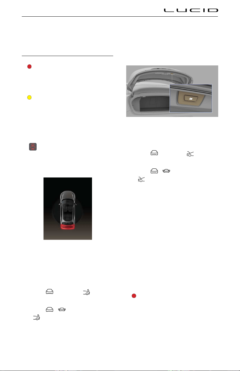
Trunk Opening and Closing
WARNING: Be aware of the risk of
serious injury when operating the trunk.
Before opening or closing, ensure no
one is in the path of the trunk's
movement.
CAUTION: Do not use excessive force
when operating the trunk manually.
The vehicle must be in P (Park) to allow the
trunk to operate.
If the trunk is not fully closed when shifting
the car out of P (Park), the system illuminates
the
Door Ajar warning indicator on the
Instrument Cluster. If the car is in D (Drive) or R
(Reverse) and the trunk is unlatched, it will be
highlighted red.
Opening the trunk
The trunk can be unlocked and opened by any
of the following methods:
- Use the Lucid mobile app.
- Select , and press the trunk
release icon on the Pilot Panel.
- Select > DOORS, and press the
trunk release icon on the Pilot Panel.
- Use the manual handle on the trunk when
doors are unlocked or if you have a key
fob with you.
Closing the trunk
To close the trunk:
- Use the Lucid mobile app.
- Select and press the trunk close
icon on the Pilot Panel.
- Select
> DOORS and press the
trunk close icon on the Pilot Panel.
- Press and release the close button on the
lower edge of the deck lid.
- Manually pull the deck lid down until the
power cinch engages.
Automatic movement stop
If anything obstructs the deck lid with enough
force to prevent it from opening or closing, it
will stop moving.
Note: The Instrument Cluster alerts you if the
decklid stops automatically.
If the decklid stops due to an obstruction,
remove it and try to open or close again. If it
cannot be opened or closed a second time, try
to operate the trunk manually.
WARNING: Exercise caution when
opening or closing the hood and
decklid in windy conditions. If a
strong gust blows against the hood
and decklid, it could close suddenly,
resulting in injury.
Opening and Closing 35

WARNING: Keep hands and fingers
away from the area between the hood
and door while closing. They may not be
detected by sensors. It's good practice
to keep your hands away from this area
while opening or closing the hood.
Accessing the Rear Cargo Area
To access the lower cargo area inside the rear
trunk, pull up on the handle of the cargo cover.
The cargo cover is not attached to the
vehicle and can be folded back or removed if
necessary.
Trunk Interior Emergency Release
A mechanical release, located on the inside of
the trunk, allows you to open the trunk if the
vehicle has no electrical power.
Note: The mechanical release will allow a
person trapped inside to get out.
1. Pull the handle firmly outward to release
the trunk latch.
2. Push upwards on the deck lid to open the
trunk.
Opening and Closing 36

Safety & Security
Safety & Security is a Settings menu item that
controls most safety & security features. To
access Safety & Security, tap the Settings icon
on the Pilot Panel and tap Safety & Security.
Shock & Tilt Alert
Vehicle sensors can detect significant impacts,
intrusions, or unauthorized towing while your
vehicle is in P (Park) and can trier alarms and
notifications.
To access Shock & Tilt Alert settings
from the Pilot Panel, select
>
Safety and Security. Alternatively, use
Settings from the Lucid Mobile App. You can
then select a notification type (both an alarm
and push notification or a push notification
only) and disable the Shock & Tilt Alert.
By default, the Shock & Tilt Alert is ON unless
manually disabled (for example, towing) and
will notify you through the Alarm and Push
Notification.
Disable the Shock & Tilt Alert for towing
or servicing. If disabled, Shock & Tilt Alert
automatically re-enables when you either
reenter the vehicle, or the next time the car is in
P (Park).
CAUTION: The sensor for the Shock
& Tilt alert is located in the center
console of the vehicle and could
accidentally be triered by a large
amount of force to that part of the
vehicle.
Disabling the alarm
If triered, disable the Shock & Tilt alarm
sequence by holding a valid key close to
the vehicle or by double-clicking the key fob
button.
Opening and Closing 37

Front Seats
Adjusting the Front Seats
WARNING: Do not adjust the driver’s
seat while driving. Doing so increases
the risk of collision.
WARNING: Before adjusting a seat,
check that the area around the seat is
free of obstacles.
WARNING: Do not sit in or operate
the vehicle until you adjust all seats
and head restraints to their proper
position. Failure to adjust seats and
head restraints increases the risk of
neck injury in the event of a crash.
Front seats can be adjusted using either the
seat-mounted switches or the Pilot Panel.
Using the Seat-mounted Switches
1. Position
Move the seat forward/backward and
adjust the seat’s height and tilt angle up/
down.
2. Backrest
Rotate the switch backward/forward to
adjust the angle of the seat back.
3. Lumbar
Press the up/down buttons to raise/lower
the lumbar support, and the left/right
buttons to adjust the firmness of the
lumbar support.
Using the Pilot Panel
To adjust the seats using the Pilot Panel, select
> SEATS.
Select the seat you want to adjust using the
DRIVER or PASSENGER tabs.
Select the seat area you want to adjust from
the side menu and then use the arrow icons to
adjust the seat.
Note: The Headrest, Thigh Support, and
Backrest Width cannot be adjusted using the
seat switches.
After adjusting the seat position, touch the
SAVE TO PROFILE button to save the seat
position to your profile. The RESTORE button
restores the driver seat position for the active
profile. Additionally, the RESTORE button is
active only when the vehicle is not in motion.
Correct Seating Position
The seat, head restraint, seat belt, and airbags
work together to maximize safety. Using these
correctly provides greater protection.
To reduce the risk of injuries in an accident,
follow these instructions:
- The driver and front passenger position
their seats so that they can correctly wear
Seating & Safety Restraints 38
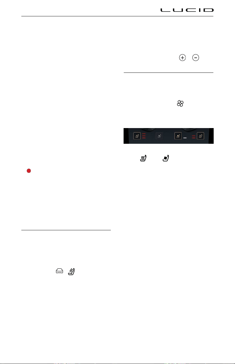
the seat belt while being as far away from
the front airbags as possible.
- Sit upright, place both feet on the floor,
and make sure that the seat back reclines
no more than 30 degrees.
- Easily reach the pedals with your feet
and slightly bend your arms while holding
the steering wheel. The distance between
the driver's chest and the center of the
airbag cover should be at least 10 inches
(254 mm).
- Grasp the steering wheel on the steering
wheel rim. Hold your hands at the 3
o'clock and 9 o'clock positions to reduce
the risk of injury to your hands or arms if
the airbag deploys.
- Adjust the D ring position to position the
shoulder section of the seat belt midway
between your neck and your shoulder. Fit
the lap section of the belt tightly as low
and snug as possible around the hips, not
the waist.
WARNING: When the seat is in the
reclined position, the shoulder belt
and lap belt does not provide proper
protection in an accident. You could
slip past the shoulder belt, be thrown
into the shoulder belt and receive neck
or other serious injuries. You could also
slide under the lap belt and receive
serious internal injuries.
Massage Feature
Both front seats have a seat massage feature
to help prevent muscle fatigue and improve
blood circulation when seated for long periods
of time.
To control seat massage programs using the
Pilot Panel, select
> MASSAGE.
Select the required seating position using
the DRIVER or PASSENGER tab. Select the
massage program you want to use from the side
menu.
Note: If you previously used the massage
feature, the massage feature selects the last
used program and intensity.
Press the START MASSAGE button to activate
the seat massage feature.
Each massage program runs for 20 minutes. A
countdown showing the time remaining shows
on the screen. To stop the massage program,
press the STOP MASSAGE button.
The intensity of the massage can be increased
or decreased by pressing the
or icons.
Seat Heating and Ventilation
Both front seats have integrated seat heaters
and ventilation.
To control seat heating and ventilation
using the Pilot Panel, select
. Press the
corresponding icon to heat or ventilate the
desired seat.
You can heat or ventilate the seats at
three different levels.
- Press once to operate at the highest level.
Three intensity indicators illuminate.
- Press twice to operate at the medium
level. Two intensity indicators illuminate.
- Press a third time to operate at the
lowest level. A single intensity indicator
illuminates.
- Press a fourth time to turn off the
selected feature.
Pressing one of the two zones on the seats
deactivates heating or ventilation for that zone.
Note: Seat heating and ventilation cannot be
used both together. Changing the seat heating
to ventilation stops the seat heating and
turns on the ventilation. Similarly, changing the
ventilation to seat heating stops the ventilation
and turns on the seat heating.
Seating & Safety Restraints 39
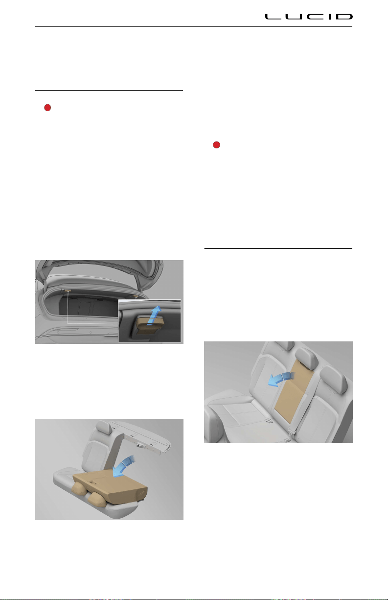
Rear Seats
Rear Seat Folding
WARNING: Secure objects carried
within the vehicle. In an impact or
sudden maneuver, unsecured objects
can cause death or serious injury.
The split rear seat allows you to fold forward all
or part of the seat to increase the load-carrying
area.
Before folding down a seat, remove any items
on the seat or in the rear footwell and adjust
the rear head restraints to the lowest position.
See Rear head restraints.
The rear seat release handles are located in the
trunk.
To fold down a rear seat, pull the corresponding
release handle.
Note: To fold down the complete rear seat, use
both release handles.
After you feel the latch release, fold the
seat forward from inside the passenger
compartment.
Raising
To return the seat to its upright position, push it
back until it locks in place. Make sure the seat
back is locked in place by trying to pull the seat
back forward.
WARNING: When the seat back is in
its upright position, make sure the
locking mechanism fully engages. If
the locking mechanism does not fully
engage, the risk of death and serious
injury increases in an accident or heavy
braking.
Note: When returning the seat to its upright
position, make sure the seat belts are not
trapped behind the backrest.
Rear Seat Pass-through
For your convenience when carrying long,
narrow items, the rear seat has a pass-through
hatch. This hatch allows you to carry long items
without having to fold the rear seat forward.
To open the pass-through hatch:
1. Fold the rear seat armrest down.
2. Pull down on the latch and fold the pass-
through hatch panel forward onto the rear
armrest.
Seating & Safety Restraints 40

To close the hatch, push the panel up until the
latch engages.
CAUTION: When passing items through
the hatch into the vehicle, make sure
not to damage the upholstery on the
seats and the armrests.
Rear Seat Heaters
All rear seating positions have seat heaters
in the seat base and seat back except the
rear center seatback, which only has a heater
function in the seat base.
Control the seat heating in the Pilot Panel
(select
> REAR), the Rear Center Console
Display (RCCD), or the capacitive buttons on
either side of the RCCD.
Press the corresponding heat icon to heat
the desired seat. You can heat the seats at
three different levels.
- Press once to heat at the highest level.
Three intensity indicators illuminate.
- Press twice to heat at the medium level.
Two intensity indicators illuminate.
- Press a third time to heat at the
lowest level. A single intensity indicator
illuminates.
- Press a fourth time to turn off the seat
heater.
Seating & Safety Restraints 41
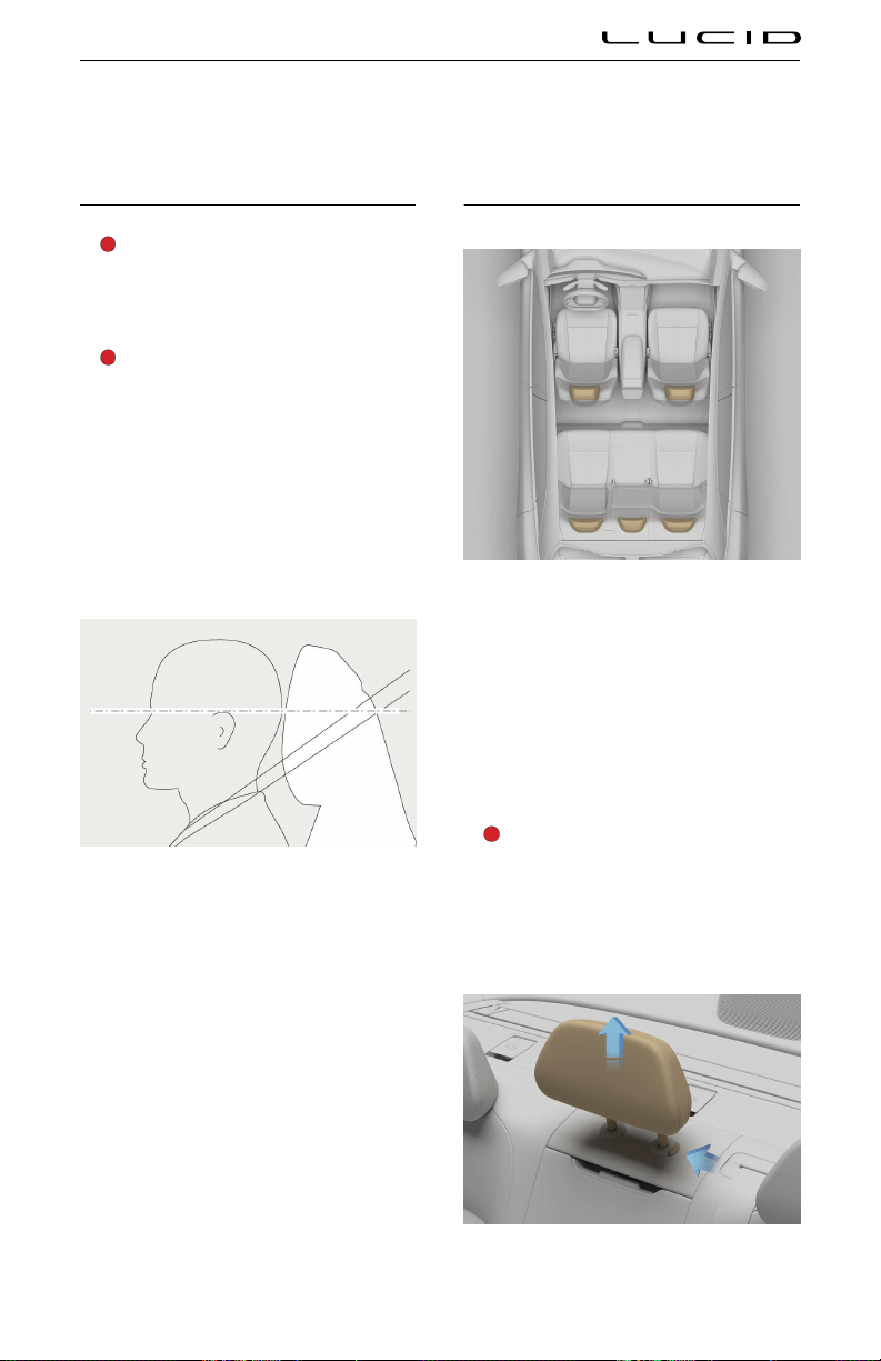
Head Restraints
Correct Head Restraint Position
WARNING: In the event of a collision,
you want the head restraint to contact
your head first, not your neck. Improper
positioning can result in serious injury,
paralysis, or death.
WARNING: All occupants, including the
driver, must adjust the headrest to the
proper position before operating the
vehicle or sitting in the vehicle's seat to
minimize the risk of neck injury in the
event of a crash.
In addition to seat belts, head restraints are
an important safety feature that, when used
properly, can reduce the risk of personal injury
(such as whiplash) in a collision.
- Head restraints should ideally be
positioned 2 inches (5 cm) or less from
the rear of the person’s head and never
more than 4 inches (10 cm).
- Adjust the head restraint, so the height,
top of the bulk restraint is at the top
of the occupant's head. Doing so will
place the thickest portion of the restraint
behind the person's head, at ear level.
Adjusting the Head Restraints
Your vehicle has an adjustable head restraint
for each seating position, with the exception of
the rear center seat.
Front head restraints
Note: The position of the front seat head
restraints can only be adjusted using the Pilot
Panel. See Using the Pilot Panel.
Rear head restraints
WARNING: Do not position the rear
head restraint to the lowest position
for an occupied rear seat. The lowest
position for a rear head restraint is in
a storage position to provide maximum
visibility out of the rear window.
Seating & Safety Restraints 42

For an occupied rear seat, press the button at
the base of the head restraint and move the
restraint upward to at least the first locked
position. Make sure the head restraint is in a
locked position during height adjustment.
The rear center head restraint is not adjustable,
only removable.
Removing a head restraint
WARNING: If the passenger's head
protrudes above the top of the seat
back, do not drive or carry passengers
with the head restraints removed from
the occupied seats. The absence of
a properly adjusted head restraint
increases the risk of serious injury or
fatality in the event of a collision.
WARNING: Remove the head restraint
from the vehicle seat when installing
a child safety seat (with the exception
of booster seats) to make sure that the
upper tether strap securely holds the
child safety seat in place.
To remove a head restraint, press the button at
the base of the head restraint, then pull up until
the head restraint slides out completely.
Reinstalling a head restraint
WARNING: Any head restraint that has
been removed must be reinstalled to
properly protect vehicle occupants.
To reinstall a head restraint, locate the head
restraint bars into the head restraint locating
holes, push the button on the side of one of
the locating holes, and push the head restraint
down until a positive lock occurs.
Seating & Safety Restraints 43

Seat Belts
Seat Belt Warnings
WARNING: Make sure the driver
and passengers wear the seat belts
correctly. Improperly wearing a seat belt
increases the risk of injury or death in a
collision.
WARNING: Always wear the seat belt
with the lap section of the belt as low
as possible and snug across your hips.
WARNING: Do not wear the seat belt
with any part of the strap twisted.
WARNING: Never wear the seat belt
with the shoulder belt under your arm.
WARNING: Never wear a shoulder belt
without the lap belt.
WARNING: Do not wear seat belts
over hard, fragile, or sharp items in
clothing (for example, pens, keys, and
eyeglasses). Pressure from the seat
belt on such items can cause personal
injury.
WARNING: Each seat belt should only
be used by one occupant. Never
attempt to use a seat belt with a child
or another person in your lap.
WARNING: Secure small children in a
proper child safety seat.
WARNING: If a seat belt cannot be
securely fastened because it is not long
enough, only use Lucid-approved seat
belt extenders.
WARNING: Using seat belt extenders
may not allow the vehicle to determine
whether a seat belt unlatches.
WARNING: Do not make modifications
or additions to the seat belt assembly
that prevent the mechanism from
taking up or removing slack. A slack
belt greatly reduces the occupant’s
protection.
WARNING: Do not attempt to remove,
repair, disassemble, or install seat belts.
Lucid recommends that Lucid Certified
Technicians should perform any
necessary repairs. Improper handling
may result in the seat belts failing to
operate correctly.
WARNING: Avoid contaminating the
seat belt assembly with any liquids,
chemicals, dirt, grit, or cleaning
products. Contamination can affect the
condition and function of the assembly.
WARNING: Seat belts showing signs of
wear (such as fraying), have been cut, or
otherwise damaged, must be replaced
by a Lucid Service Center.
WARNING: If a seat belt fails to latch or
does not fully retract when not in use,
contact Lucid Customer Care to have
the assembly inspected and possibly
replaced.
WARNING: Any seat belts that were
in use during a collision must
be inspected or replaced by Lucid
Certified Technicians, even if there is
no apparent damage to the assembly.
WARNING: Take care not to damage the
seat belt by allowing any part of it to
become trapped in the door.
Wearing Seat Belts
WARNING: All occupants must wear
seat belts no matter the driving
distance. Failure to do so increases the
risk of serious injury or fatality in an
accident.
Seat belts and child restraint systems are the
most effective means of restraining vehicle
occupants from impact forces, which minimizes
the danger of injury from interior impacts and
the effects of whiplash. Wearing a seat belt is
required by law in most states.
All seating positions are equipped with three-
point inertia retractor seat belts. Inertia
retractor seat belts are tensioned automatically
and allow freedom of movement during normal
driving conditions.
The seat belt retractor automatically locks,
preventing occupants' movement whenever
your vehicle experiences the force associated
Seating & Safety Restraints 44
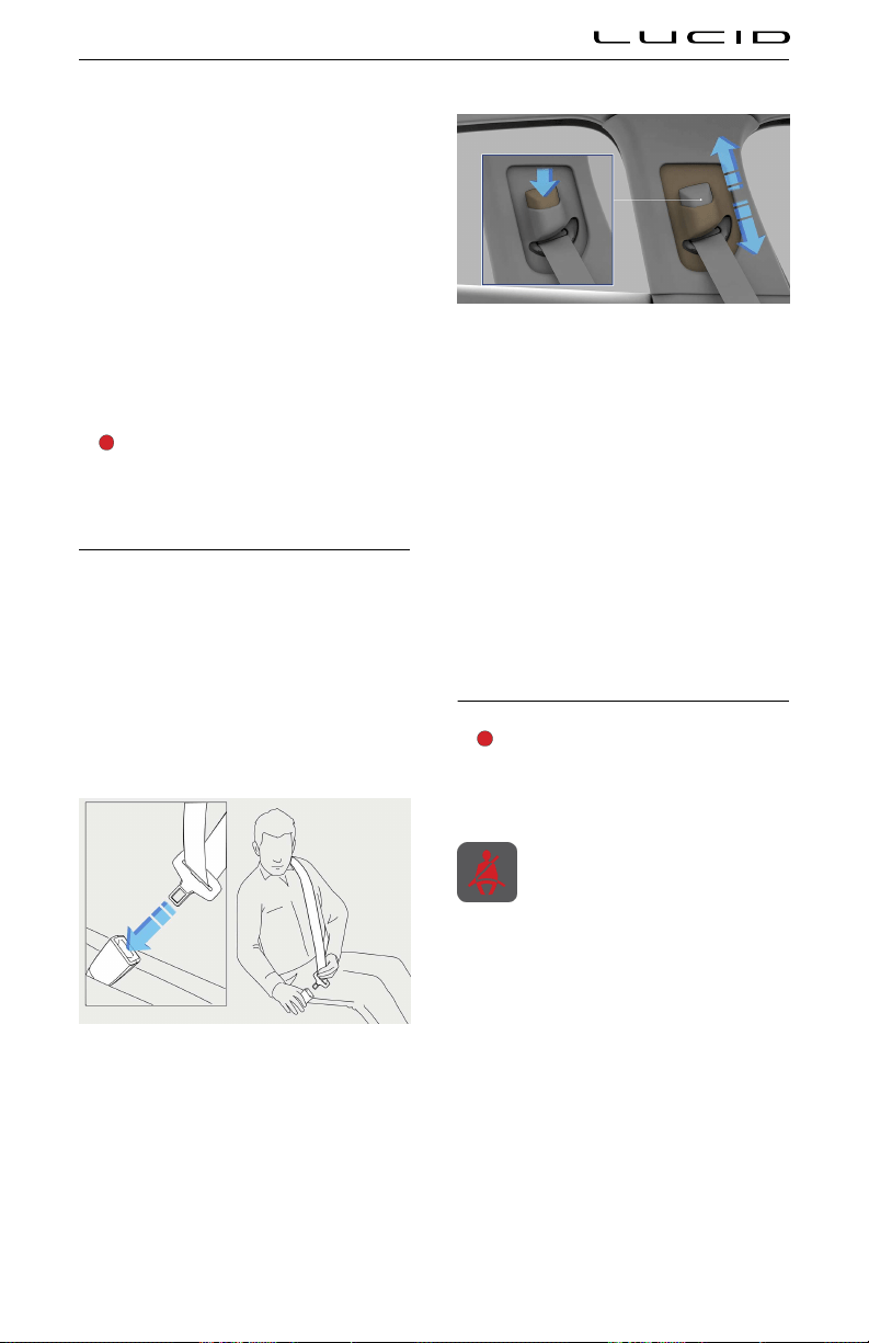
with hard acceleration, braking, cornering, or
impact in a collision. The retractor may also
lock when driving on steep hills or slopes.
Automatic Locking Retractor (ALR)
All rear passenger seating positions are
equipped with an Automatic Locking Retractor
(ALR) to securely hold child safety seats.
When the seat belt completely extends and
then allowed to retract (even slightly), the
retractor locks so that it cannot be extended.
To disengage the ALR, allow the belt to fully
retract. See Installing Seat Belt Retained Child
Seats.
The front passenger seat has an ALR.
WARNING: Lucid does not recommend
installing a child seat in the front
passenger seat.
Fastening the Seat Belt
1. Position the seat correctly. See Correct
Seating Position.
2. Pull the seat belt out slowly, making sure
that it is not twisted or damaged.
3. Buckle the seat belt by inserting the latch
patch fully into the buckle. A distinct
"click" indicates that the seat belt is
securely locked in place.
4. The height adjuster of the front seat belts
can be adjusted.
Press the button on the seat belt adjuster
on the door pillar and move the belt up or
down. Adjust the seat belt to the highest
position possible for the seat belt to be
mid-way between the shoulder and the
neck, on the collar bone.
5. Tighten the seat belt across the lap
and rest the seat belt on the hips by
pulling the diagonal section up towards
the shoulder.
Releasing the belt
To release the seat belt, press the red button on
the buckle. The seat belt automatically retracts.
Seat belt reminders
WARNING: All occupants must wear
seat belts. Never disregard or attempt
to disable the seat belt reminder if it
activates.
The seat belt reminder on the
Instrument Cluster alerts you if a seat
belt for an occupied front or rear seat
is unbuckled.
If the vehicle speed is less than 12 mph
(20 km/h), the red warning indicator solidly
illuminates, with no warning chime.
If the vehicle speed is more than 12 mph
(20 km/h), the red warning indicator flashes
continuously and an intermittent chime sounds.
If all occupants are wearing seat belts and the
warning indicator stays on, re-fasten all seat
belts in use to make sure they are correctly
latched. Remove any heavy objects (such as
a briefcase) from any unoccupied seats. If the
indicator remains on, contact a Lucid Service
Center.
Seating & Safety Restraints 45

In addition to the seat belt reminder, a graphic
of the seat layout displays on the left side of
the instrument cluster. The seat layout displays
the detected occupied seats and the seat belt
use status.
When the seat location displays a green
indicator, it indicates that the seat
position is occupied and the seat belt is
fastened.
When a seat location displays a red seat
belt indicator, it indicates that the seat
position is occupied but the seat belt is
not fastened.
Using Seat Belts When Pregnant
WARNING: Pregnant women must wear
seat belts to protect themselves and
their unborn child.
WARNING: Do not place anything
between you and the seat belt to
cushion the impact in the event of a
collision.
Wear the lap portion of the seat belt as low
as possible across the hips, not the waist.
Position the shoulder part of the belt between
the breasts and to the side of the abdomen.
Make sure that the seat belt has no slack and
is not twisted.
For any concerns about wearing seat belts,
consult with your physician.
Seat Belt Pre-tensioners
WARNING: If a seat belt pre-tensioner
activates, it must be replaced. After
an impact or collision, even if there is
no obvious damage, always have the
seat belts checked and (if necessary)
replaced by a Lucid Service Center.
The seat belts for the front and outboard
rear seating positions are equipped with
pre‑tensioners that work either independently
or in conjunction with the airbags in a severe
front or side-impact collision, depending upon
the severity of a crash.
Note: A pre-tensioner activates if the seat belt
is already buckled at the time of the collision.
The pre-tensioners automatically retract the
seat belts, reducing any slack in both the lap
and shoulder portions of the belts, thereby
reducing the forward movement of the seat belt
wearer.
The seat belt pre-tensioners can only activate
once before a Lucid Service Center must
replace them.
If a pre-tensioner activates, the airbag
warning indicator displays on the
Instrument Cluster.
Note: Even if the pre-tensioners activate, the
seat belts still function as restraints. Continue
to wear the seat belts if the vehicle remains in a
drivable condition.
Seating & Safety Restraints 46

Testing Seat Belts
WARNING: Regularly check the
condition of all seat belts. Replace seat
belts if you notice damage to the belt
straps, fittings, retractor mechanisms,
or buckles. Damaged seat belts may
not operate properly in the event of an
accident.
WARNING: When seat belts are not in
use, they should be fully retracted and
not hanging loose. If a seat belt does
not fully retract, contact a Lucid Service
Center.
There are three tests you should perform when
checking seat belts:
1. With the seat belt fastened, give the
shoulder belt strap at the buckle a quick
upward pull. The buckle should remain
securely locked.
2. With the seat belt unfastened, unreel the
belt to its limit. Check that it unreels
smoothly with no snatches or snags.
Visually check the belt for wear. Allow the
belt to retract, checking that retraction is
smooth and complete.
3. With the belt half unreeled, hold the strap
and quickly try to pull more strap out. The
mechanism must lock automatically and
prevent further unreeling.
If any issues arise during these tests, contact a
Lucid Service Center immediately to have the
seat belt replaced.
Seating & Safety Restraints 47

Child Safety Seats
Guidelines for Seating Children
All child restraint systems are designed to be
secured by lap belts or the lap belt portion of
the lap-shoulder belt.
WARNING: Do not use a child restraint
on a seat with an operational airbag in
front of it. There is a risk of death or
serious injury when the airbag deploys.
Crash statistics show that children are
safest when properly restrained in a
child or infant restraint system that is
secured in a rear seating position.
WARNING: Do not use a forward-facing
child seat until the child using it is
above the minimum weight of 20 lb (9
kg) and able to sit up unaided. Up to
the age of two years, a child's spine and
neck are not sufficiently developed to
avoid injury in a frontal impact.
WARNING: Do not allow a baby or
infant to be held or carried on the
lap. The force of a crash can increase
effective body weight by as much as
30 times or higher, depending upon the
crash severity, making it impossible to
hold onto the child. At all times, restrain
children in age- and size- appropriate
child seats to reduce the risk of injury
in a crash.
Lucid designed and fitted your vehicle's seat
belts for adults and larger children. For the
safety of infants and children under 12, it is
important to restrain them in a suitable child
safety seat appropriate for their age and size.
Fit a child seat that has been approved for
use in your vehicle. Follow the manufacturer's
fitting instructions exactly. You can contact
Lucid for a list of approved child seats. See
Contacting Lucid Motors on page 210. The
rear seat supports both iSize and ISOFIX child
seats.
Note: Legislation that governs how and where
children should be carried when traveling in
a vehicle is subject to change. It is the
responsibility of the driver to comply with all
current regulations.
WARNING: Do not use a rear-facing
child restraint on a seat protected by
an airbag in front of it. In the event of
an airbag deployment, this could lead
to serious injury or fatality of a child
seated in a front seat.
While it is possible to disable the front
passenger airbag, this should not be relied
upon to protect your child.
Lucid strongly
advises that you DO NOT use a rear-facing
child seat on the front passenger seat.
Choosing a Child Safety Seat
WARNING: Children age 12 and under
should ride in the rear seats using a
child safety seat suitable for the child’s
age and weight.
WARNING: Children should ride
rear-facing and use the child
restraint's integrated 5-point harness
in conformity with possible local laws
and the recommendations of the Child
Safety Seat manufacturer. Check to
make sure children riding in your
vehicle are riding in the appropriate
child restraint.
Child restraints accommodate different ages,
sizes, and weight ranges of children. Many child
restraints are designed to allow children to
ride rear-facing. Carefully read and follow all
instructions and warnings provided by the child
safety seat manufacturer, and on all labels
attached to the child safety seat.
Use the following tables to help you determine
the best type of restraint for a child. There are
also some general rules for each category.
Weight Group Rear Outer
Seat
Rear Center
Seat
Group 0 Under 22
lb (10 kg)
U -
Group 0+ Under 29
lb (13 kg)
U -
Group I 20-40 lb
(9-18 kg)
U, UF -
Group II 33-55 lb
(15-25 kg)
U, UF -
Group III 48-76 lb
(22-36 kg)
U, UF -
Seating & Safety Restraints 48

U: Universal belt rearward child restraint
system
UF: Universal belt forward child restraint
system
Weight Group Front
Passenger
Seat
Rear
Outer
Seat
Rear
Center
Seat
Group
0
Under 22 lb
(10 kg)
- IL -
Group
0+
Under 29 lb
(13 kg)
- IL -
Group I 20-40 lb
(9-18 kg)
- IL -
Group
II
33-55 lb
(15-25 kg)
- IL,
IUF
-
Group
III
48-76 lb
(22-36 kg)
- IL,
IUF
-
IL: Any semi-universal LATCH/ISOFIX child
restraint system
IUF: Any universal LATCH/ISOFIX child
restraint system
Seating Larger Children
WARNING: Make sure the booster seat
or vehicle seat properly supports the
child's head. The seat back must be at
or above the center of the child's ears.
WARNING: Make sure to properly fit the
vehicle seat belt onto the child with the
shoulder portion of the belt away from
the face and neck and the lap portion
of the belt lying across the child’s lap,
not over the stomach.
WARNING: When a booster seat is not
in use, do not leave it loose in the
vehicle. In a sudden stop or collision,
it could strike the occupants or seat
backs and cause serious injury. Secure
the booster seat or remove it from the
vehicle entirely.
If a child is too big to fit into a child safety
seat but too small to safely fit into the standard
seat belts, use a booster seat appropriate for
the child’s age and size.
Carefully read and follow all the instructions,
warnings, and labels attached to the booster
seat and provided by the booster seat’s
manufacturer.
Always check and adjust every child’s seat belt
for every trip.
Children who are big enough to wear the
shoulder belt properly and comfortably, and
whose legs are long enough to bend over the
front of the seat when their back is against the
seat back, should use the seat belt in a rear
seat.
Installing Child Safety Seats
WARNING: When installing any child
safety seat, it is strongly recommended
to always remove the head restraint
from the vehicle seat.
WARNING: Correctly anchor child
safety seats. Incorrectly anchoring the
child safety seats may result in a
significant risk of injury to the child in
the event of a collision or emergency
braking.
WARNING: After installing a child
safety seat in the vehicle, do not adjust
the vehicle seat, as this can loosen the
safety seat attachments. Remove the
safety seat before adjusting the vehicle
seat position. When the vehicle seat
has been adjusted, reinstall the safety
seat.
Not all child restraint systems are the same,
and they do not all install in the same way.
There are two types of installations:
- Those that you secure to the vehicle seats
by the seat belts; and
- Those that you secure using LATCH/
ISOFIX child seat anchor points built into
the rear seat frame.
All new and most older child restraint systems
also use an upper tether strap that attaches to
an anchorage point on the parcel shelf.
Note: Check the manufacturer's instructions
to see which installation method to use.
For some systems, you can use either
installation method. Always follow the child
restraint manufacturer’s instructions and
recommendations.
Seating & Safety Restraints 49

Installing LATCH or ISOFIX Child Seats
WARNING: Child seat anchorages are
designed only to withstand the loads
imposed by a correctly installed child
safety seat. Under no circumstances
are they to be used for adult seat belts,
harnesses, or attaching other items or
equipment to the vehicle.
WARNING: Never attach two child
safety seats to one anchor point. In
a collision, one anchor point may be
incapable of securing both seats.
WARNING: If the restraint is not
correctly anchored, there is a risk of
serious injury to the child in the event
of a collision or emergency braking.
The outer rear seats are equipped to accept
LATCH/ISOFIX restraints.
Note: Only a seat belt retained child seat can
be used in the center rear seating position.
To install a LATCH/ISOFIX child seat:
1. The lower LATCH/ISOFIX anchorage
points are located between the seat back
rest and rear cushion, indicated by child
seat identification tabs on the seat.
2. Position the child seat on the vehicle
seat.
3. Attach the child seat latches onto
the LATCH/ISOFIX lower anchor points,
following the manufacturer’s instructions
to connect and tighten them.
4. Securely connect and tighten the latches.
To do this, attempt to pull the child seat
away from the vehicle seat and twist
it from side to side. Even if the child
seat appears secure, check the anchor
points visually to make sure for correct
attachment.
If the child seat moves more than 1 inch
(2.5 cm) from side to side or front to
back, it is too loose. If you cannot tighten
the latches any further, try a different
recommended seating location or another
child safety seat.
Seating & Safety Restraints 50
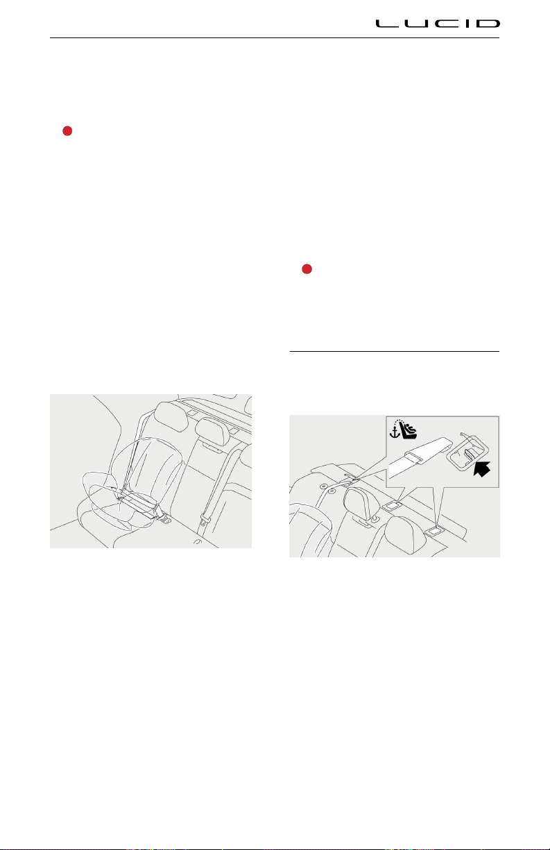
5. If the child seat has an upper tether
provided, fit and tighten the upper tether
correctly. See Attaching Upper Tether
Straps.
WARNING: When the combined weight
of the child plus the child restraint is
more than 64 lb (29 kg), you should not
use the lower LATCH/ISOFIX anchors
with the child seats or booster seats
that have an integrated safety belt. Use
the seat belt instead.
Installing Seat Belt Retained Child Seats
First, make sure that the child falls into the
correct weight range for the child seat being
used. See Choosing a Child Safety Seat on
page 48.
The following is a general procedure for
installing a seat belt retained child restraint.
You should always read and follow the
instructions provided by the manufacturer of
the child safety seat you are installing.
1. Place the child safety seat in the vehicle
seat and fully extend the seat belt to
engage the ALR. See Automatic Locking
Retractor (ALR). Route the seat belt to
secure the child safety seat and secure
the buckle following the manufacturer’s
instructions.
2. Allow the seat belt to retract. Firmly push
the safety seat into the vehicle seat and
remove all slack in the seat belt.
3. If the safety seat has an upper tether,
attach it to the back of the vehicle seat.
See
Attaching Upper Tether Straps.
4. Check that the safety seat is not loose.
Do this by holding the safety seat by the
belt path and sliding it side to side and
front to back.
If it moves more than 1 inch (2.5 cm)
from side to side or front to back, then
it is too loose. If you cannot tighten the
safety seat any further, try a different
recommended seating location or another
child safety seat.
Attach a child safety seat using the
lap belt or the lap belt portion of a
lap-shoulder belt in accordance with the
instructions of the manufacturer of the
child seat.
WARNING: Children could be
endangered in a crash if their child
restraints are not properly secured in
the vehicle.
Attaching Upper Tether Straps
There are upper tether strap anchors provided
for each rear seating position.
To attach the tether straps:
1. Remove the head restraint from the
vehicle seat. See Adjusting the Head
Restraints.
2. Pass the tether strap over the top of the
seat.
3. Open the protective cover located behind
the headrest.
4. Attach the tether strap hook to the tether
anchor point on the parcel shelf.
Ensure that the tether strap hook is
facing the correct way according to the
Seating & Safety Restraints 51

manufacturer’s instructions and that the
strap is not twisted.
5. Tighten the tether strap according to the
manufacturer's instructions.
Child Safety Seat Warnings
WARNING: To ensure children are
safely seated, follow all instructions
provided in this document and by the
manufacturer of the child safety seat.
WARNING: Always check and adjust
every child’s safety harness or seat belt
for every trip.
WARNING: Avoid dressing the child
in bulky clothing (such as thick or
puffy coats) and do not place any
objects between the child and the
restraint system, as these practices
could introduce slack to the restraints
and reduce their effectiveness.
WARNING: Children should never be
left unattended in the vehicle, even
when secured in a child safety seat.
WARNING: According to collision
statistics, children are safer when
properly restrained in the rear seats
than in the front seat.
WARNING: Never use seat belt
extenders on a seat belt that is used
to install a child safety seat or booster
seat.
WARNING: Regularly inspect and check
the installation of all child safety seats.
Replace any seats or harnesses that
show signs of wear.
WARNING: Never use a child safety
seat that has been in a collision.
Have the seat inspected or replaced
as described in the child safety seat
manufacturer’s instructions.
Seating & Safety Restraints 52
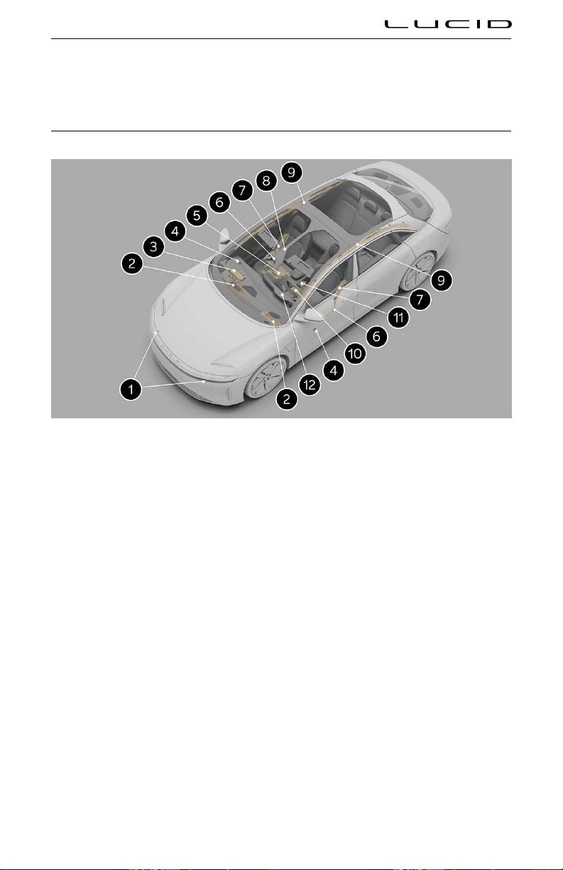
Airbags
Location of Airbags and Airbag Sensors
1. Front impact sensors
2. Knee airbag
3. Front passenger’s airbag
4. Side impact sensor (front door)
5. Passenger seat OCS sensor
6. Front seat belt pre-tensioner
7. Side airbags (seat-mounted)
8. Passenger airbag status indicator (overhead console)
9. Curtain airbag
10. Driver’s airbag
11. Airbag control module
12. Airbag SRS warning indicator
Note: The illustration shows approximate airbag locations.
Seating & Safety Restraints 53

Airbag Safety Information
WARNING: Even with airbags, the driver
and occupants must always wear their
seat belts to minimize the risk of
severe injury or death in the event of
a collision.
WARNING: Do not attach or place
objects on or near the front airbags, the
side of the front seats, the headliner
at the side of the vehicle, or any
other location that could interfere with
the inflation of an airbag. Objects can
cause serious injury if the vehicle is in
a collision severe enough to cause the
airbag to deploy.
WARNING: For the curtain airbags
to deploy correctly, the roof lining
and A‑post trim must be undamaged
and installed correctly. Any damage
or suspect installation should be
referred to a Lucid Service Center for
inspection.
WARNING: Front-seat occupants
should not place any part of their arms,
body against the steering wheel or
dashboard area, as an inflating airbag
can cause fractures or other injuries.
WARNING: Do not use seat covers
in the vehicle. A seat cover could
interfere with the deployment of the
seat-mounted side airbags in the event
of a collision.
WARNING: Airbags inflate with
considerable speed and force. To
reduce the risk of injuries, ensure that
all occupants are wearing seat belts
and are correctly seated, with seats
positioned as far back from any front
airbags as possible.
WARNING: Never use a child safety
seat or seat young children on a seat
with an operational airbag in front of
it. Doing so can cause serious injury or
death if the airbag deploys.
WARNING: To ensure correct inflation
of the side airbags, maintain
an unobstructed gap between an
occupant’s torso and the side of the
vehicle.
WARNING: Occupants should not lean
their heads against doors. Doing so can
cause injury if a curtain airbag deploys.
WARNING: Do not allow occupants to
obstruct the operation of an airbag by
placing feet, knees, or any other part of
the body on or near an airbag.
WARNING: Contact Lucid first if you
are planning to modify your vehicle
for a person with disabilities in a way
that may affect the airbag system. See
Contacting Lucid Motors.
Airbag Safety Labels
Airbag safety labels are on the sun visors for
the driver and front passenger.
How the Airbags Work
WARNING: The airbags are a
Supplemental Restraint System,
providing additional protection in
certain types of collisions only; they do
not replace the need to wear a seat
belt.
WARNING: Occupants not properly
restrained in designated seating
positions are at high risk of death or
serious injury in the event of airbag
deployment.
WARNING: Do not use a child restraint
on a seat with an operational airbag in
front of it. There is a risk of death or
serious injury if the airbag deploys.
Airbags inflate when sensors detect an impact
that exceeds deployment thresholds. These
thresholds are designed to predict the severity
of a crash in time for the airbags to help protect
the vehicle's occupants.
Airbags inflate instantly and with considerable
force, accompanied by a loud noise. The
inflated airbag and the worn seat belts limit
the occupants' movement to reduce the risk of
injury.
The front airbags are not designed to inflate as
a result of:
- Rear collisions
- Vehicle rollover
- Slow speed front impacts
- Side impacts
Seating & Safety Restraints 54

- Driving over bumps or potholes
Therefore, significant superficial damage can
occur to the vehicle without the airbags
inflating or, conversely, a relatively small
amount of not easily visualized structural
damage can cause airbags to inflate.Heavy
braking
Types of Airbags
Front airbags
The front airbags are designed to protect
the head and chest of the driver and front
passenger from impact with the steering wheel
and dashboard panel components.
The front airbags fitted to your vehicle are
advanced airbags. This type of airbag is
designed to reduce airbag-related injuries to
children or small-statured adults.
Your vehicle has front seat position sensors.
These sensors help make sure that the airbag
inflates with less force if the seat is closer to
the airbag than if the seat was further away,
regardless of the impact severity.
An occupancy sensor is built into the front
passenger seat. If the sensor detects the weight
of an infant or small child, the system will
automatically turn off the passenger’s front
airbag. However, Lucid does not recommend
that you seat an infant or small child in
the front passenger seat. See Guidelines for
Seating Children on page 48.
No objects should be placed over or near the
airbag on the instrument panel because the
object could cause harm if the vehicle is in a
crash.
Note: If there is no front seat passenger
detected, the passenger front airbag will not
activate. See Front Passenger Seat Occupant
Classification System (OCS) on page 56.
Side airbags
WARNING: Maintain a gap between the
side of the vehicle and the torso; this
enables correct inflation of the seat-
mounted side airbags.
WARNING: Do not use seat covers or
accessory seat covers on a front seat,
as these will prevent the side airbag
from deploying correctly in an accident.
If in doubt, contact a Lucid Service
Center.
WARNING: Lucid recommends a Lucid
Service Center performs all repairs.
Incorrectly performed repairs to the
side airbag system could impair
function and lead to serious injury or
death.
The side airbags are designed to protect the
thorax region of the torso and pelvis and only
deploys in the event of a severe side impact.
They do not inflate as a result of frontal or rear
impacts only. The airbags on the non-impacted
side of the vehicle do not deploy.
Knee airbags
The knee airbags are designed to work in
conjunction with the deployment of the front
airbags. When deployed, the knee airbags limit
the forward motion of the driver or front
passenger by restricting leg movement, thereby
positioning the occupant so that the front
airbags work more effectively.
Seating & Safety Restraints 55

Curtain airbags
WARNING: Make sure that passengers
do not lean their heads against the
doors. In the event of a collision,
the curtain airbag deploys from the
headliner and may cause injury.
WARNING: Never hang or attach heavy
objects from the grab handles on the
headliner. The hooks are for lightweight
garments (not for hard objects).
The curtain airbags are designed to protect the
head in severe frontal crashes with a lateral
component, severe side impacts, or rollovers.
They do not inflate in all frontal impacts and do
not inflate alone in a rear impact.
Note: Curtain airbags can help prevent
occupants from being thrown from the vehicle
in the event of a vehicle rollover.
Obstruction of Airbags
WARNING: Do not allow passengers to
obstruct the operation of the airbags
by placing feet, knees, any other part
of the body, or any other objects in
contact with, or in close proximity to, an
airbag module.
WARNING: Do not attach or position
items on an airbag cover that could
interfere with the inflation of the airbag
or be propelled inside your vehicle and
injure occupants.
WARNING: Never place your arm over
an airbag cover. A deploying airbag
can cause serious fractures or other
injuries.
For the airbags to correctly deploy, obstructions
cannot intervene between an airbag and the
occupant.
The following are examples of the type of
obstructions that could impede the correct
operation of the airbags or jeopardize personal
safety in the event of an airbag deployment:
- Accessories attached to or obscuring an
airbag cover (for example, attached to the
roof lining, door pillar trim, or the front
seat backrests)
- Items of hand luage, or other objects
placed on an airbag cover
- Feet, knees, or any other part of the
anatomy in contact with, or in close
proximity to, an airbag cover
- Head, arms, or any part of the anatomy
in contact with, or in close proximity to, a
seat-mounted side airbag
- Objects (such as items of clothing)
hanging from the handles attached to the
headliner
- Objects (such as items of clothing or
cushions) draped over the part of the
front seat containing the airbag
- Seat covers/accessory seat covers over a
front seat; in particular, seat covers that
have not been designed for use with seat-
mounted side airbags. If in doubt, consult
your Lucid Service Center.
Front Passenger Seat Occupant Classification System (OCS)
WARNING: Lucid strongly advises
against seating a child on the front
passenger seat, even if the passenger
airbag is Off. All occupants age 12 and
under should ride in the rear seats. See
Child Safety Locks on page 30.
WARNING: The full weight of the
front seat passenger should always
be directly on the seat cushion. The
passenger should never lift themselves
off the seat cushion by using the
armrest in the door or the center
console, by pressing their feet on the
floor, by sitting on the edge of the
seat cushion, or by pressing against the
backrest in a way that reduces pressure
on the seat cushion. The passenger
should never place anything (such as
a cushion) between themselves and the
seat that could cause OCS to disable
the front passenger's airbag.
Deployment of the front passenger airbag is
not always beneficial for small or lower-weight
occupants and could be harmful to children/
infants in restraint systems.
The front passenger seat is fitted with an
occupancy sensor that controls the status of
the front passenger airbag based on the weight
of the occupant.
Note: The occupancy sensor system only
controls the deployment of the front passenger
airbags and passenger side airbag. It does
Seating & Safety Restraints 56

not affect the deployment of the seat belt pre-
tensioner or the passenger curtain airbag.
The occupancy sensor system meets the
regulatory requirement of FMVSS 208 and
automatically detects when deployment of the
front passenger airbag may be unnecessary or
potentially harmful.
A status message on the overhead console
indicates whether the front passenger airbag is
currently OFF.
You should always check whether the
passenger airbag status indicator shows the
correct status for the current seat occupancy.
If you think the passenger airbag status is
incorrect, check for the following:
- Objects lodged underneath the seat
- Objects wedged between the seat
cushion and the center console
- Objects hanging off the back off the seat
- Cargo interference with the seat
- Rear-seat passengers pushing or pulling
on the front passenger seat
Any of the conditions listed above may cause
the occupancy sensor to incorrectly interpret
the weight of the occupant or object as either
heavier or lighter than the real weight.
Depending on the input received from the
occupancy sensor, the passenger airbag status
indicator operates as follows:
Front
Passenger Seat
Occupancy
Passenger Airbag
Status
Passenger
Airbag
Status
Indicator
Airbag
SRS
Warning
Indicator
Completely
empty/ low-
weight
object
*1
Deactivated PASS
AIR BAG
OFF
-
Child
restraint
seat with
infant
Deactivated
*2
PASS
AIR BAG
OFF
-
Child Deactivated
*3
PASS
AIR BAG
OFF
-
Adult Activated
*4
- -
System
malfunction
Deactivated PASS
AIR BAG
OFF
ON
*1
A low-weight object or occupant is classified
as weighing less than 52 lb (23.5 kg). The
movement of a low-weight occupant or object
while your vehicle is in motion may cause the
status indicator to switch states occasionally.
*2
Never install a rear-facing child restraint
system on the front passenger seat. A forward-
facing child restraint system should only be
installed on the front passenger seat when it
is unavoidable.
*3
For some children (a child in a seat, booster
seat, or convertible seat), the system may not
recognize them as a child. Factors that may
affect this can be the physique or posture.
*4
The system judges a person of adult size as
an adult. When a smaller adult sits in the front
passenger seat, the system may not recognize
them as adults, depending on their physique
and posture.
Note: It is possible to receive an intermittent
indicator status with an empty seat. This is
part of the system's behavior and it does
not affect the status of the front passenger
airbags. However, if the status indicator is
not permanently illuminated when the seat
is empty, contact a Lucid Service Center
immediately.
If you still believe that the airbag status
indicator is incorrect, have your passenger ride
in the rear of the vehicle and contact a Lucid
Service Center to have the system checked.
Seating & Safety Restraints 57

Front passenger seat OCS precautions
WARNING: Failure to observe the
following precautions regarding the
front passenger OCS may cause death
or serious injury.
- Wear the seat belt properly. See
Wearing Seat Belts.
- Make sure the front passenger's seat
belt latch plate is not inserted into
the buckle before someone sits in
the front passenger seat.
- If an adult is seated in the front
passenger seat, and the PASS
AIR BAG OFF indicator is displayed,
ask the passenger to sit up straight,
well back in the seat, with feet on
the floor, and with the seat belt worn
correctly. If the PASS AIR BAG OFF
indicator remains displayed, ask the
passenger to move to a rear seat or
move the front passenger seat fully
rearward. In either case, contact a
Lucid Service Center to help correct
the issue.
- Child restraint systems installed on
the rear seat should not contact the
front passenger seat back.
- Do not recline the front passenger
seat back so far that it contacts a
rear seat or an object in the rear
of the vehicle. This may cause the
PASS AIR BAG OFF indicator to be
displayed. Return the seat back to
a position where it does not touch
the seat or object. Keep the front
passenger seat back as upright as
possible when the vehicle is moving.
Reclining the seat back may lessen
the effectiveness of the seat belt
system.
- Make sure the PASS AIR BAG OFF
indicator is not displayed when using
a seat belt extender for the front
passenger. If the PASS AIR BAG OFF
indicator is displayed, disconnect
the latch plate from the seat belt
buckle and reconnect the seat belt.
If you continue to use the seat belt
extender while the
PASS AIR BAG
OFF indicator is displayed, the
airbags for the front passenger will
not activate correctly. This could
cause death or serious injury in the
event of a collision.
- Do not apply a heavy load to the
front passenger seat.
- Do not put objects underneath the
front passenger seat.
- Do not allow rear seat passengers
to put weight on the front passenger
seat by putting their hands or feet on
the seat back.
- Do not let a rear passenger lift the
front passenger seat with their feet
or press on the seat back with their
legs.
- Do not allow a passenger to kick the
front passenger seat or subject it to
a severe impact. This could cause
the Airbag SRS warning indicator
to be displayed and prevent the
system from operating correctly in
an impact. Contact a Lucid Service
Center if the warning indicator is
displayed.
- Do not modify or remove the front
seats.
- Do not modify, cover, or replace the
upholstery on the front seat.
Effects of Airbag Inflation
WARNING: When airbags deploy, a
fine powder is normally released. This
powder can cause irritation. Thoroughly
flush the power from the eyes and skin,
including any cuts or abrasions. The
powder may aravate asthma for some
people.
WARNING: Following inflation, some
airbag components are hot. Do not
touch until they have cooled.
After inflation, the airbags deflate to provide
a gradual cushioning effect for the occupants
and unobscure the driver’s forward vision.
If airbags inflate or your vehicle has been in
a collision, always have the airbags, seat belt,
and all associated components checked and (if
necessary) replaced by Lucid.
Seating & Safety Restraints 58

Safety features
Along with the inflation of the airbags, the
following also occurs to assist you and any
recovery personnel:
- Doors unlock
- Hazard warning lights turn on
- Interior lights turn on
- High-voltage power is isolated
Airbag SRS Warning Indicator
You will be alerted of any airbag
system malfunction by a red warning
indicator on the Instrument Cluster.
The components monitored by the system
include:
- Airbag modules
- Seat belt pre-tensioners
- Airbag diagnostic control unit
- Crash sensors
- Airbag wiring harnesses
- Seat occupancy sensors
- Seat belt buckle sensors
When the vehicle is On, the airbag control
unit monitors the readiness of the system’s
electrical circuits.
You should contact a Lucid Service Center if
the warning indicator:
- Fails to illuminate when the vehicle starts.
- Fails to extinguish within approximately
6 seconds after the vehicle starts.
- Illuminates while driving the vehicle.
Airbag Service Information
WARNING: Do not attempt to service,
repair, replace, or modify any part of the
airbag system. This includes wiring or
components in the vicinity of the airbag
components. Doing so may cause the
system to trier or render the system
inoperative, either of which may result
in death or serious injury.
WARNING: Any notable damage to
airbag components or covers (for
example, tears, burns, holes, chemical
or detergent damage, or previous
accidental damage), however produced,
may cause the airbag module(s) to
fail. Make sure a Lucid Service Center
repairs or replaces any damaged
components.
WARNING: If you need to dispose of
an airbag or seat belt pre-tensioner,
contact a Lucid Service Center.
Incorrect disposal procedures could
cause personal injury.
Seating & Safety Restraints 59
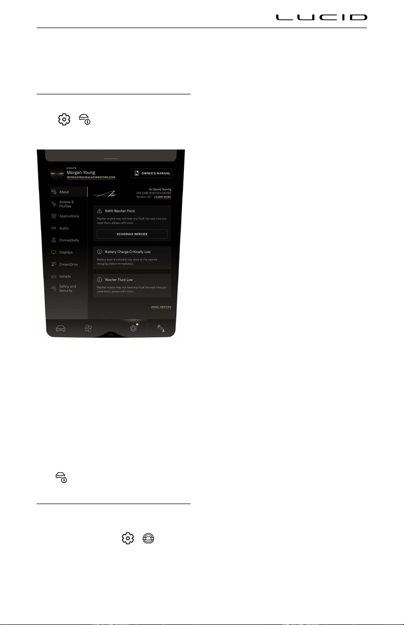
Driver Information
Vehicle Information and Alerts
To access information about your vehicle,
select
> About Vehicle on the Pilot
Panel.
This screen shows you the following:
1. Vehicle model
2. Vehicle Identification Number (VIN)
3. Vehicle software version
4. Alerts that were recently displayed on the
Instrument Cluster
Note: If new alerts are available, a
notification badge will appear on the
About Vehicle icon.
Trip Information
Trip information is displayed on the left vehicle
widget of the Instrument Cluster. To reset or
change the display, select
> Vehicle on
the Pilot Panel.
To change the trip displayed on the Instrument
Cluster, select either "since last charge," "TRIP
A," or "TRIP B".
There are two trip range memories available,
TRIP A and TRIP B. To reset either trip memory,
press the RESET button next to the TRIP listing.
Driving & Operating 60

Pilot Panel
Extending and Retracting the Pilot Panel
The Pilot Panel retracts to reveal extra storage.
Touch and hold the arrow at the base of the
Pilot Panel. The panel will retract into the dash,
revealing the storage space. Touch the arrow
again to extend the Pilot Panel.
Driving & Operating 61

Instrument Cluster
Instrument Cluster - Overview
Note: The illustration below is for demonstration purposes. The information in your vehicle display may
have differences depending upon the current software version and market region.
1. Trip information area
2. Charge meter, see Charge and Power Meter on page 67
3. Power meter, see Charge and Power Meter on page 67
4. Turn signal indicators, see Turn Signals on page 76
5. Navigation widget
6. Odometer
7. Speedometer
8. Battery State of Charge widget, see Battery State of Charge Indicator on page 67
9. Gear selection indicator, see Selecting a Drive Mode on page 72
10. Warning indicator, see Warning Indicators on page 63
Driving & Operating 62
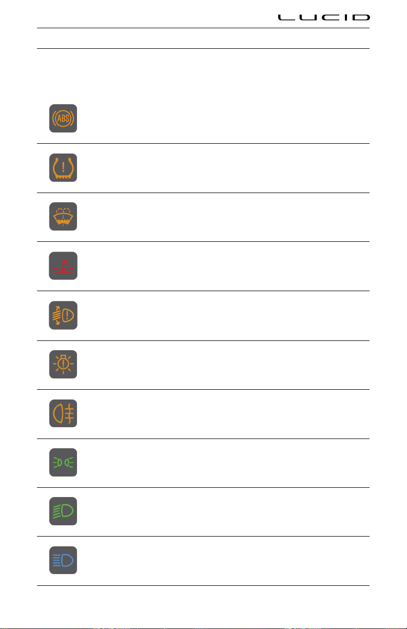
Warning Indicators
The following icons may be displayed on the Instrument Cluster to alert you to which features are
operating or if there are any systems with faults.
For further information, refer to the relevant section in this manual.
Anti-lock Braking System (ABS) disabled or system fault detected
Tire Pressure Management System (TPMS) low tire pressure (solid) or system fault detected
(lashing)
Low washer luid level
Low coolant level
Headlight leveling fault detected
Exterior light fault detected
Rear fog light active
Side/Position lights active
Low beam headlights active
High beam headlights active
Driving & Operating 63
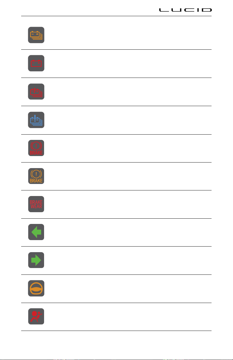
Low high-voltage battery State of Charge (SoC)
12V battery charging system fault detected
High temperature detected for high-voltage battery
Low temperature detected for high-voltage battery
Brake system fault is detected, or the level of the brake luid is low
Brake booster fault is detected
Excessive brake wear detected
Left turn signal active
Right turn signal active
Highway Assist active
Airbag system fault detected
Driving & Operating 64
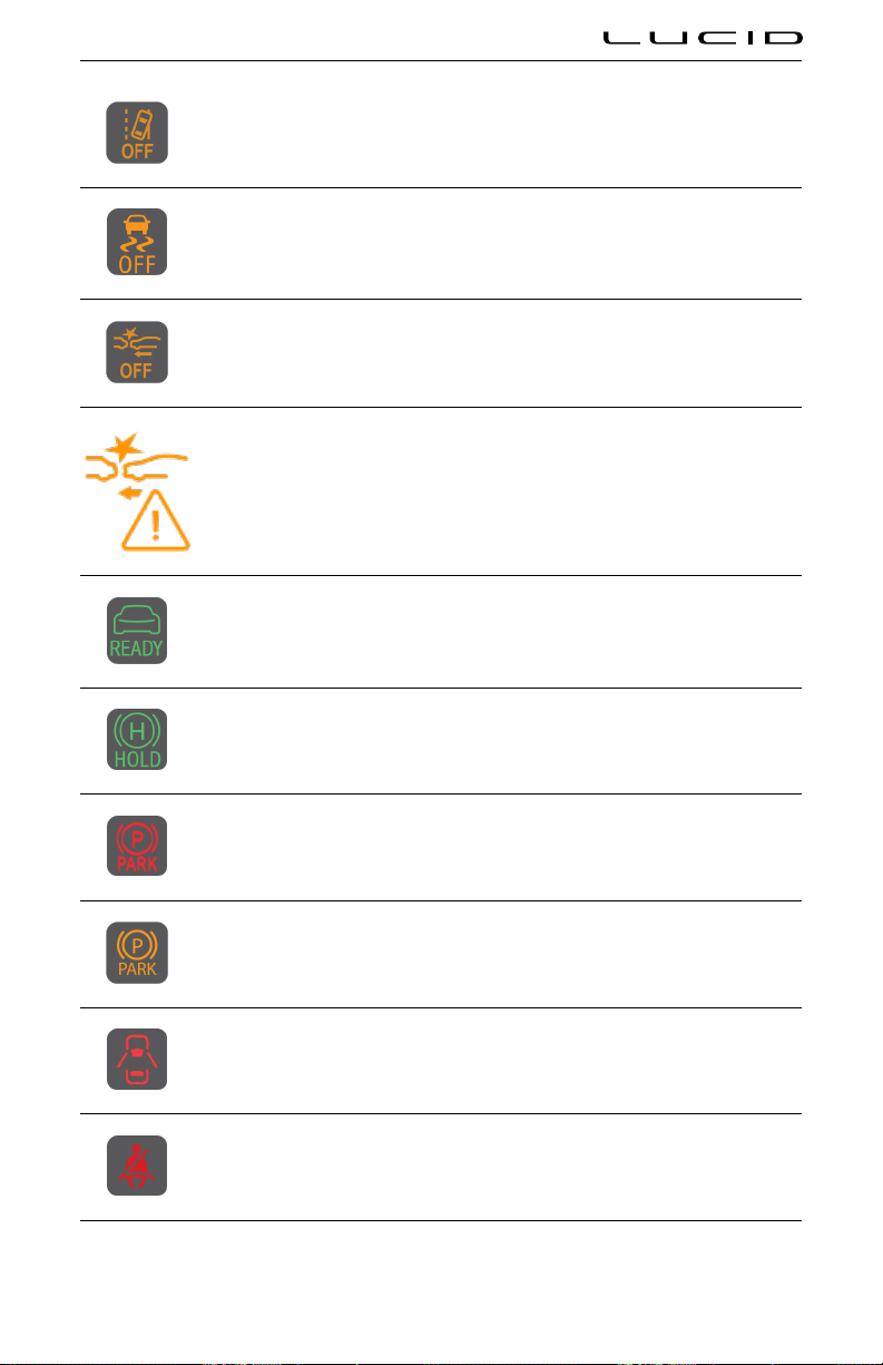
Lane Departure Protection disabled or system fault detected
Lucid Stability Control system is in a reduced state
Collision Protection disabled
Collision Protection fault detected
Drive mode enabled
Vehicle hold is currently active and holding vehicle
Parking brake applied
Parking brake fault detected
Door open or ajar
Seat belt not fastened
Driving & Operating 65
System warning
System alert
Driver's monitoring camera cannot detect their face
Drowsy Driver alert
Lucid Stability Control operating when lashing. If indicator stays solid, a fault is detected.
Limited Power Mode active
Steering system fault detected
Driving & Operating 66
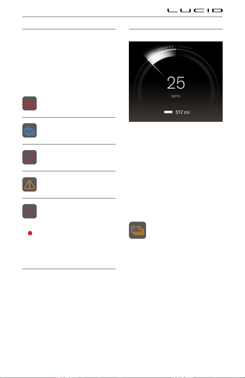
High-Voltage Drive System Failure
If the high-voltage drive system detects a
critical problem with the battery or the drive
motors, a red warning message and instructions
will be displayed in the center of the Instrument
Cluster, accompanied by audible alerts.
Other Instrument Cluster indicators related to
the battery or drive motors are accompanied
by warnings, information, and/or instructions
displayed in the left widget.
High temperature detected for high-
voltage battery
Low temperature detected for high-
voltage battery
12V battery charging system fault
detected
System alert: A detected problem
requires your attention and caution.
System warning: For safety, a detected
problem requires immediate attention/
action.
WARNING: If any of these notifications
are displayed while driving, there may
be a reduction in performance until the
issue is resolved.
Charge and Power Meter
The meter that arcs over the speedometer
shows the current power use of the vehicle,
and whether the vehicle is using or generating
power.
If the vehicle is using power, then the meter fills
to the right. If the vehicle is generating power,
then the meter fills to the left.
Battery State of Charge Indicator
The battery icon below the speedometer shows
the current State of Charge (SoC) level for
the high-voltage battery pack, along with an
estimated vehicle range based on the remaining
charge.
As you drive the vehicle or operate any of
its features, the battery pack’s charge will be
depleted, and the icon will reflect the change in
SoC and vehicle range.
As the charge level approaches lower levels,
the Instrument Cluster will display notifications
accordingly. See Preserving battery pack
health.
When the remaining battery pack
charge falls below 10mi/16km, a
yellow low battery indicator will
display on the Instrument Cluster.
Note: Lucid recommends that if the SoC falls
below 50mi/80km, consider finding somewhere
you can charge the vehicle. Remember the
vehicle range is only an estimate, and the
actual drivable distance can vary according to
environmental and terrain conditions.
Driving & Operating 67

Starting and Powering O
Starting
Your vehicle does not require a key to be turned
or a button to be pressed to start it. If a paired
key fob, valet card or phone is recognized when
the driver’s door is opened, the Cockpit and
Pilot panels will power on indicating the vehicle
is ready to operate.
Accessory mode
When you first get into the vehicle and sit in the
driver’s seat, the vehicle will be in Accessory
mode. The Cockpit and Pilot panels will both
power On.
The Instrument Cluster will show you the
current vehicle status, e.g. door open and
battery charge level.
In Accessory mode, all the electrical features
and controls can be operated but the vehicle
cannot be driven.
Note: If you try to select a gear in Accessory
mode without pressing the brake pedal, the
message Push Brake will be displayed.
Drive Mode
While sitting in the driver’s seat, press the
brake pedal to put the car in Drive Mode. The
vehicle searches for a recognized key fob or
mobile key. If a known device is detected, the
vehicle is allowed to start. If no known device is
detected, a message displays on the Instrument
Cluster.
If a valet card is used to open the door, the
driver will be prompted to enter a PIN code
before allowing to drive. See Starting on page
68.
Note: You cannot put the vehicle into Drive
Mode while a charging cable is connected.
The display on the Instrument Cluster will
change to show the Speedometer, Power meter,
and the PRND display. The indicator lights
briefly illuminate during system check.
The Ready to Drive icon is displayed
on the Instrument Cluster.
Select a gear to drive the vehicle. See Selecting
a Drive Mode on page 72.
Note: The Drive Mode enabled icon disappears
when the vehicle is in motion.
Key fob not detected
If no recognized key fob is detected inside the
vehicle when you attempt to shift out of Park,
a message appears on the Instrument Cluster
asking the driver to enter a PIN before the
vehicle can be put into Drive.
If the vehicle still fails to start, try using another
key fob or the Valet card. If the vehicle still
can’t be started, please contact Lucid.
Note: A number of factors can affect whether
the key fob is detected by the vehicle. These
include a low key fob battery, interference from
other devices using radio signals and objects
between the key and receiver.
Key no longer detected
If your vehicle is in Drive mode and the vehicle
can no longer detect the key fob inside the
vehicle, a warning message will be displayed on
the Instrument Cluster.
Note: Always make sure you have the key fob
with you before making a journey, as you will
be unable to restart the vehicle once it has
powered off.
Powering Off
When you have finished driving and selected
P (Park), the parking brake will engage and all
systems will remain operational.
Note: If the vehicle is not in 'Park' and is
stationary, when the driver door is opened, the
vehicle will automatically shift to P (Park).
If the key fob is still detected in the area,
and the brake pedal has not been pressed, the
vehicle will power down after 15 minutes. If the
key fob is not detected in the area, the vehicle
will power down.
Driving & Operating 68
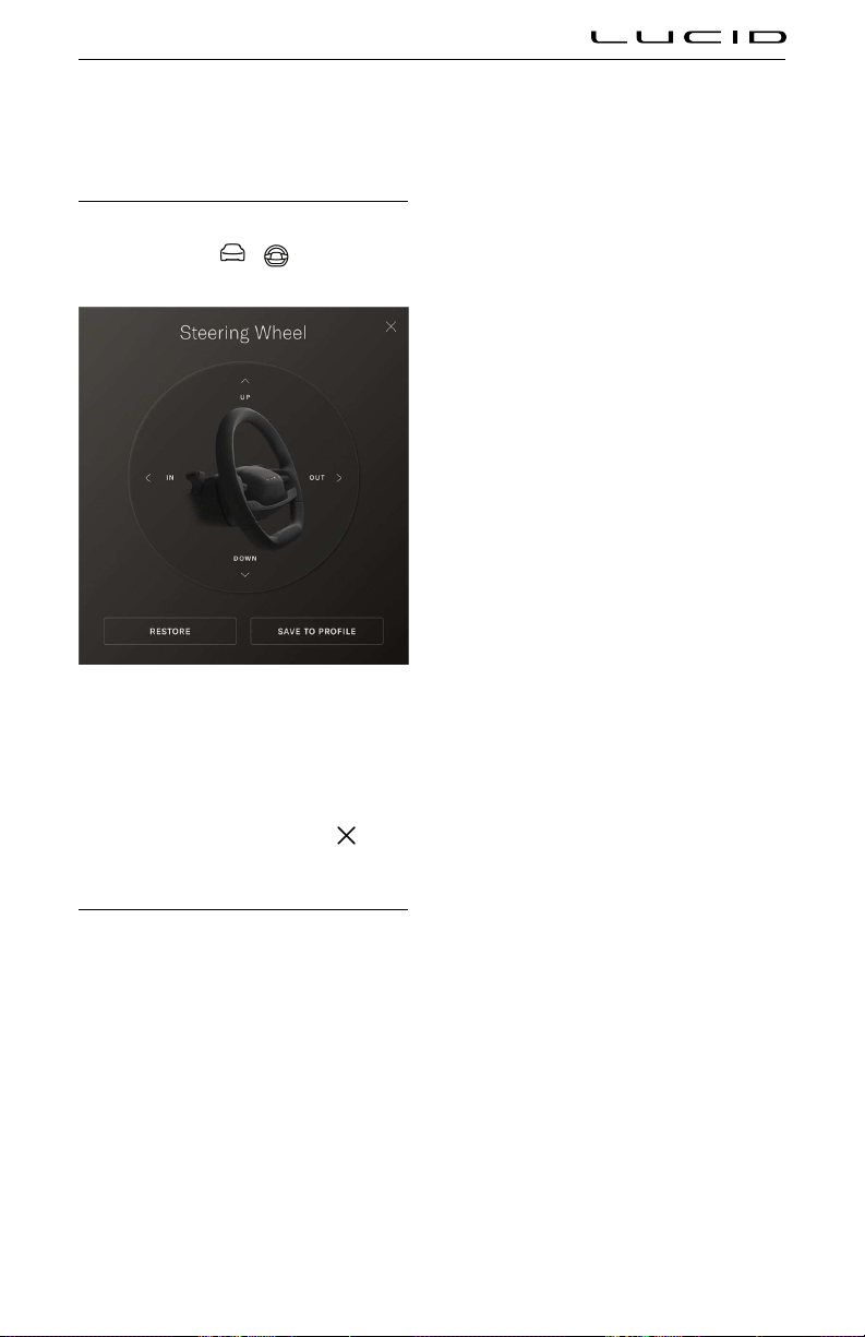
Steering Wheel
Adjusting the Steering Wheel Position
Use the Pilot Panel to adjust steering column
position by touching
> .
Press the Up/Down/In/Out arrows to adjust the
steering wheel to your preferred position.
Once an adjustment has been made, press
RESTORE to return to the previous position, or
press SAVE TO PROFILE to save this position
under the current User Profile. Press
to
close.
Steering Feel and Sensitivity
The feel and sensitivity of the steering system
is determined by the current driving mode
selected for the vehicle. See Drive Modes.
Driving & Operating 69

Steering Wheel - Right Controls
1. For information about Left Controls, please see Steering Wheel DreamDrive Controls
2. Controls the volume for all media, audio, and phone calls
○ Push up to raise volume
○ Push down to lower volume
○ Press center button to play/pause, take an incoming call, or mute the microphone during a
call
3. Skip to the previous song or station
4. Skip to the next song or station
5. Press to invoke Alexa. Press and hold to invoke either the voice assistant of either CarPlay or
Android Auto
Driving & Operating 70

Horn
To sound the horn, press the center pad on the
steering wheel
Driving & Operating 71
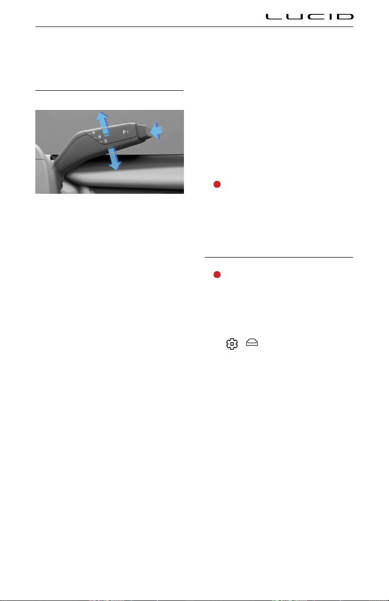
Drive Selector
Selecting a Drive Mode
With the vehicle in Drive mode, move the right
steering column lever up or down to select
Reverse or Drive. The Instrument Cluster will
show the current selection.
When the vehicle is in P (Park), you must also
press the brake pedal before selecting D (Drive)
or R (Reverse).
Note: If you try to make a selection that is
prohibited due to the current vehicle speed,
a chime will sound and a message will be
displayed on the Instrument Cluster.
R (Reverse)
Push the lever up and release to select R. R can
only be selected when the vehicle is stationary
or its forward speed is less than 5 mph (8
km/h).
N (Neutral)
Allows the vehicle to roll freely unless the
brakes are applied. Push the lever up or down
from the currently selected gear and release to
select N.
D (Drive)
Push the lever down and release to select D.
You can only select D when the vehicle is
stationary or its speed is less than 5 mph
(8 km/h) in reverse.
P (Park)
When
P is selected, the parking brake is
automatically applied.
With the vehicle stationary, you should press
the end of the gear selector to select
P.
Note: P is automatically engaged whenever you
connect a charging cable to the charging port.
This is to prevent the vehicle being moved while
still connected.
Note: If the vehicle is in D or R, P will
automatically be selected if you open the
driver’s door and get up from the driver’s seat.
WARNING: It is the responsibility of the
driver to always ensure the vehicle is
in P (Park) before exiting. Never rely on
the vehicle to automatically shift into
P (Park) for you; it might not work in all
circumstances.
Creep Mode
WARNING: Do not rely on Creep to
keep your vehicle stationary on a hill.
To avoid collisions or property damage,
you should always apply the brake to
remain stopped when on a hill.
Creep is enabled or disabled via the Pilot Panel.
Select
> Vehicle > Drive Settings.
When Creep is On, releasing the brake pedal
and tapping the accelerator causes the vehicle
to slowly move forward in D (Drive), or
backward in R (Reverse). On steeper slopes
or hills it may be necessary to apply the
accelerator to move the vehicle forward.
When Creep is Off, the vehicle will either
be in a free-rolling state or hold stationary,
depending on the selected stopping mode.
Driving & Operating 72
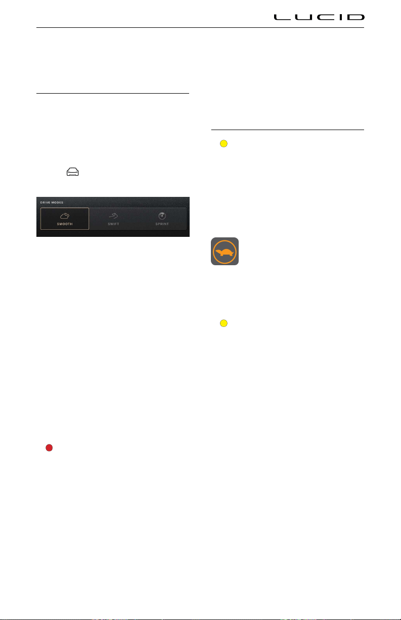
Drive Modes
Drive Modes
Your vehicle can be set to your preferred driving
and regenerative braking modes. You can opt
for more comfortable and less responsive
vehicle controls in order to increase energy
efficiency.
Use the Pilot Panel to select Drive Mode by
touching
.
Smooth
Smooth mode offers a relaxed and range-
focused driving experience. When activated, the
steering, braking and suspension systems will
be optimized for comfort, and the powertrain
response will be smoothed.
Swift
Swift mode is designed for spirited driving.
When activated, steering, braking and
suspension systems will be optimised for
a dynamic driving experience. Powertrain
responsiveness, and available power and
torque, will be increased. Upon powering the
vehicle off and on again, the drive mode will
return to Smooth.
Sprint
WARNING: It is recommended that
this mode is used only by
advanced and skilled drivers, in
suitable environments, and with Lucid-
specification summer tires installed.
Sprint Mode enables the maximum power
and torque of your vehicle, designed for
short duration bursts of intense performance.
Steering, braking and suspension systems are
optimized for stability and control. To use
this mode, you must select it and agree to a
disclaimer. Upon powering the vehicle off and
on again, the drive mode will return to Smooth,
and the disclaimer requirement will reset.
Note: This mode cannot be selected if the
vehicle is using the guest profile. Please login
to enable this mode.
Limited Power Mode
CAUTION: It is recommended that
when driving in Limited Power Mode
you should travel in the lane of slower
moving traffic and be prepared to stop.
Limited Power Mode automatically activates
if a fault is detected by the vehicle’s drive
controller to protect the powertrain. When
activated, vehicle power is reduced, speed and
performance are limited.
When Limited Power Mode is active,
an indicator will be displayed on the
Instrument Cluster.
If Limited Power Mode activates while you are
driving, do not panic! Pull off the road when it
is safe to do so and call roadside assistance.
See Contacting Roadside Assistance.
CAUTION: Limited Power Mode should
NOT be used for sustained operation of
the vehicle.
Driving & Operating 73

Mirrors
Adjusting the Exterior Side Mirror Position
WARNING: Dependent upon the type
of mirror glass fitted to your vehicle,
distances may be difficult to judge
accurately. Objects viewed in the mirror
may be closer than they appear.
Use the Pilot Panel to adjust side mirror
position by touching
> .
1. Press the LEFT or RIGHT button to select
the mirror.
2. Press the Up/Down/In/Out arrows to
adjust.
Once adjusted, press RESTORE to return to the
previous position or press SAVE TO PROFILE
to save this position under the current User
Profile. Press
to close.
Folding and unfolding
To manually fold/unfold the exterior side
mirrors via the Pilot Panel, press
> .
Heating and defrosting
The exterior side mirror defrost feature
activates when the rear defrost button is
activated. See Defrost.
Interior Rear View Mirror
Manually adjust the position of the rear view
mirror for the desired view behind you.
The mirror will automatically dim in proportion
to the level of glare detected from a following
vehicle’s headlights.
Note: This feature is disabled when the vehicle
is in R (Reverse) to provide an unimpeded view
in reverse.
Driving & Operating 74
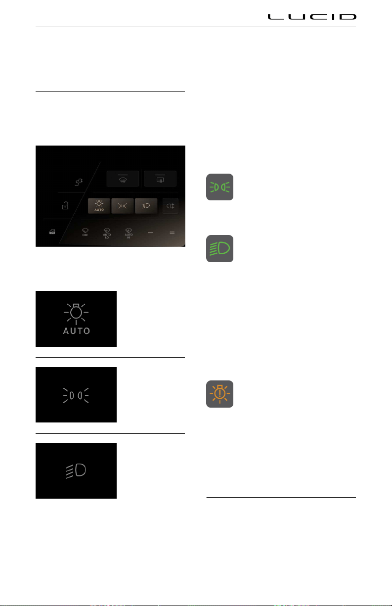
Exterior Lights
Exterior Lights Control
The exterior vehicle lights are controlled using
the left lever on the steering column and the
left cockpit panel.
Touch the corresponding icon to operate the
exterior lights as follows:
AUTO lights
Position lights
Low beam headlights
AUTO lights
The low beam headlights, tail lights and license
plate lights will automatically switch On when
the ambient light falls below a pre-defined
level.
The lights will switch Off when the ambient
light rises above that level.
Note: The lights will switch On whenever the
windshield wipers are operating.
Position lights
The position (side marker) lights
indicator is displayed on the
Instrument Cluster whenever the
position lights are On.
Low beams
The low beam indicator is displayed
on the Instrument Cluster whenever
the low beams are On.
Daytime running lights
Note: The functionality and operation of
daytime running lights will vary according to
market requirements.
In regions that require the vehicle’s lights to be
On even during the day, the daytime running
lights will automatically switch On whenever
the vehicle is in Drive mode.
Light failure
If the vehicle detects that an exterior
light is not working the light failure
indicator will be displayed on the
Instrument Cluster. This will be
accompanied by a message as to which bulb
has failed.
Lights on warning
If the exterior lights have been left On, a chime
will sound when the driver’s door is opened.
High Beam Headlights
Note: The headlight high beams will only
operate if the low beams are on.
Driving & Operating 75
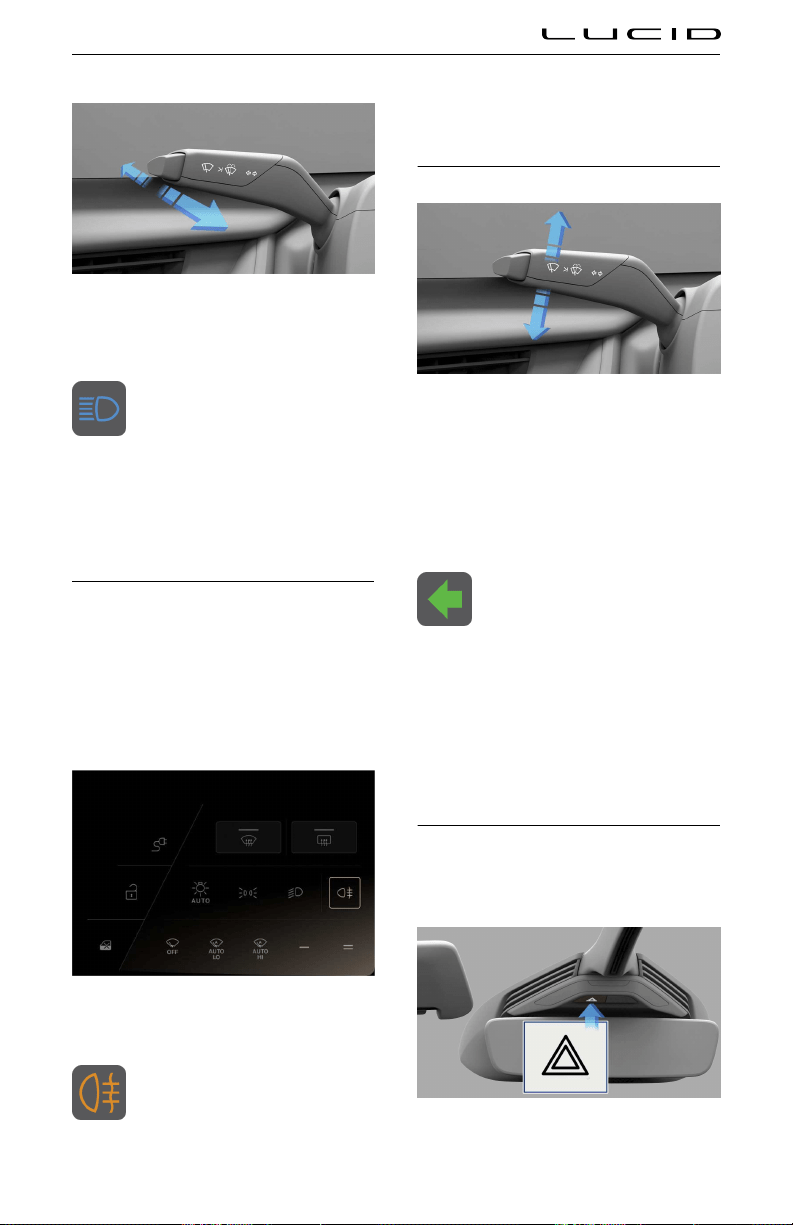
To turn on the high beam headlights, push the
left steering column lever away from you. To
cancel, pull the lever towards you.
The high beam indicator is displayed
on the Instrument Cluster whenever
high beams are On.
Headlight high beam flash
You can flash the headlight high beams by
pulling the lever fully towards the steering
wheel and releasing it.
Rear Fog Light
Note: Regulations concerning the use of fog
lights vary from country to country.
The rear fog light is considerably brighter than
ordinary taillights and should only be used
to help other road users see your vehicle in
low-visibility conditions such as fog or heavy
snowfall.
Use the left Cockpit Panel to turn the rear fog
lamp On or Off.
The rear fog light indicator is
displayed on the Instrument Cluster
whenever the rear fog light is On.
Note: The rear fog light is automatically turned
Off each time the vehicle is powered On, and
will need to manually turned On if required.
Turn Signals
The turn signals are activated by moving the
left steering column lever down to operate the
left turn signals, or up to operate the right turn
signals.
The turn signals will continue to operate until
automatically canceled by the steering wheel,
or by returning the lever to the central position.
When a turn signal is activated, the
corresponding turn signal indicator is
displayed on the Instrument Cluster.
You will also hear a clicking sound
when the turn signal is operating.
Lane changes
To signal a lane change, momentarily hold the
lever up or down against the spring pressure
and then release; the turn signals will flash
three times to indicate a lane change.
Hazard Warning Lights
Note: The hazard warning lights can be
operated even when a key fob is not in the
vehicle.
Driving & Operating 76

To turn on the hazard warning lights, press the
switch located on the overhead console. All
turn signals will flash along with the turn signal
indicators on the Instrument Cluster.
Press the switch again to switch off the hazard
warning lights.
Note: You should only use hazard warning
lights in an emergency to warn other road
users of a breakdown or other potential danger.
Remember to switch off when the hazardous
situation has been resolved.
After a collision
If you are involved in a collision that causes
the airbags to be deployed, the hazard warning
lights will automatically switch on.
Driving & Operating 77
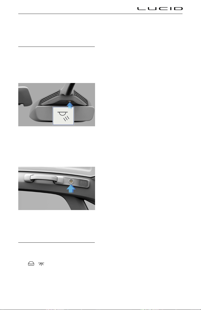
Interior Lights
Interior Lights
The interior lights automatically switch On
when a vehicle door is opened, and Off when
all doors are closed.
Front seats
To turn the front interior light On or Off, use
the switch located on the overhead console or
touch either light individually.
Rear seats
To turn either of the two rear passenger reading
lights On or Off, press the center of the lamp
lens.
Ambient Lighting
Ambient lighting illuminates the footwells, cup
holders, and accent areas with your choice of
colored lighting. To customize ambient lighting,
press
> THEMES on the Pilot Panel.
Note: If enabled, the ambient lights come on
whenever the vehicle is On. If ambient lighting
is turned off, it will remain off until you turn it
back on.
Tap an ambient lighting theme to select.
If desired, use the center color wheel to
customize brightness. The center section of
the color wheel has an ambient lighting on/off
switch. If turned off, the touch interface
disappears until you switch ambient lighting
back on.
Driving & Operating 78
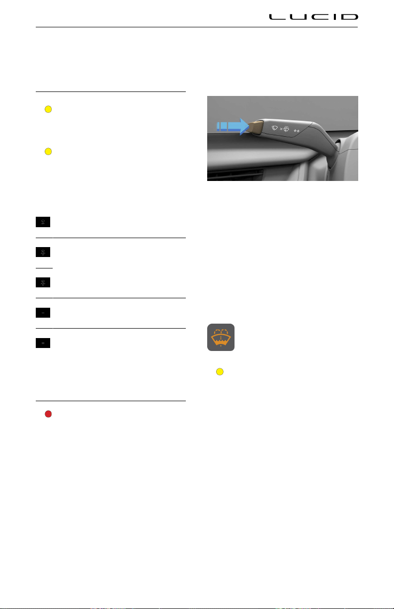
Wipers and Washers
Wipers
CAUTION: Do not activate the wipers if
they are frozen to the windshield; this
could damage the wiper blades and the
wiper motor.
CAUTION: Do not activate the wipers
on a dry windshield; this could damage
or cause unnecessary wear to the wiper
blades.
Control wipers using the icons in the left
Cockpit Panel as follows:
OFF
In AUTO, the vehicles rain sensor detects
whether or not it is raining and activates
the wipers as required. The sensitivity of the
wiper activation is selected by the LO or HI
icons.
LOW speed continuous wipe
HIGH speed continuous wipe
Note: Intervals between wipes reduce as the
vehicle’s speed increases.
Washers
WARNING: Operating the washers in
cold weather could cause the fluid
to freeze on the windshield, obscuring
your vision and causing a collision.
Use the windshield heater to warm the
windshield to reduce the possibility of
the fluid freezing.
The left steering column stalk button is used
for wiper controls. To get a single dry wipe,
press the button to the first detent once, or
press and hold at the first detent for multiple
dry wipes. To spray the washer fluid press the
button to the second detent or press and hold
at the second detent for multiple wash-wipe
cycles.
The wipers will operate with washer. Release
the button to stop the washer. After the button
is released, the wipers will make several extra
sweeps.
If the fluid level in the washer
reservoir is low, the warning indicator
will be displayed on the Instrument
Cluster.
CAUTION: Do not operate the washers
when the fluid reservoir is empty or
frozen. This can cause the washer
pump to overheat and fail.
Driving & Operating 79

Brakes
Braking Systems
WARNING: It is critical to occupant
safety that your braking systems are
always functioning properly. If you
experience any braking issues or
receive any fault messages regarding
the braking system, contact a Lucid
Service Center immediately.
WARNING: Driving through heavy rain
or water can have a temporary adverse
effect on braking efficiency.
CAUTION: Do not rest your foot on
the brake pedal while the vehicle is
in motion unless you are applying the
brake pedal. Resting your foot on the
brake pedal can cause premature break
wear.
The foot pedal hydraulically-operated brakes
are electrically boosted, but only when the
vehicle is On. If the vehicle loses power when
driving, you will need to apply more force on
the brake pedal and you will experience longer
stopping distances.
If the brake fluid level in the
reservoir is low, a red brake indicator
and a notification message will be
displayed on the Instrument Cluster.
See Checking Brake Fluid.
If the yellow brake indicator displays
on the Instrument Cluster, a brake
system fault has been detected.
Contact a Lucid Service Center as
soon as possible to have the brakes inspected.
Anti-Lock Braking System (ABS)
WARNING: Always maintain an
appropriate distance from the vehicle
in front. ABS cannot overcome the
physical limitations of trying to stop the
vehicle in too short a distance.
WARNING: The braking distance on
road surfaces that are wet, slippery
or loose is always increased; even for
vehicles equipped with ABS.
WARNING: Always drive with due care
and attention to your surroundings and
road conditions. ABS will not correct
driver errors.
Your vehicle is equipped with an Anti-lock
Braking System (ABS) that helps prevent the
wheels from locking during hard braking or
when braking on roads with reduced grip.
During braking, the ABS monitors the speed of
each wheel and varies the brake fluid pressure
at each wheel to prevent the wheels from
locking. This system helps maintain steering
ability during maximum brake application.
When ABS activates, you may experience the
following conditions:
- Pulsations in the brake pedal
- A slight drop of the brake pedal
- Clicking or grinding noises
- ABS warning indicator flickering on and
off as the system activates
These conditions demonstrate that ABS is
operating and are not a cause for concern.
Maintain a firm and steady pressure on the
brake pedal while experiencing the pulsation.
Emergency braking
WARNING: Do not pump the brake
pedal. This interrupts the operation of
the ABS system and increases your
stopping distance, which could lead to
a collision.
In an emergency, fully press the brake pedal
even when the road surface is slippery.
ABS warning indicator
The ABS indicator displays on the
Instrument Cluster, along with a
notification message.
- If the indicator is flashing, a fault has
been detected.
Driving & Operating 80
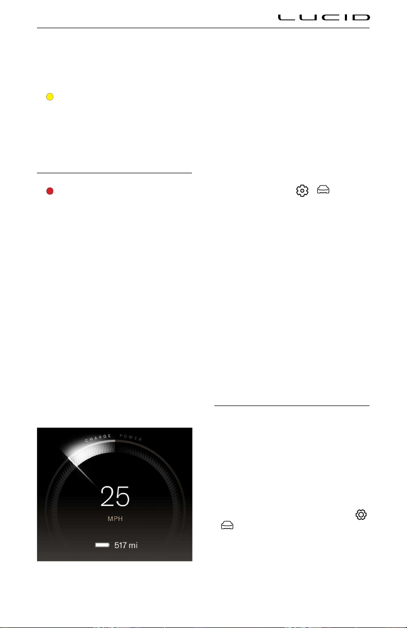
- If the indicator remains displayed, the
system has been disabled.
Contact a Lucid Service Center as soon as
possible to have the fault repaired.
CAUTION: The pedal-operated braking
system remains operational even when
the ABS warning indicator illuminates.
Be aware that braking distances may
increase and wheels may lock under
heavy braking.
Regenerative Braking
WARNING: If driving the vehicle in
reduced traction conditions (that is,
icy or snowy conditions), the use
of High regenerative braking level
may cause traction control to operate
more frequently. Lucid recommends
switching to Standard level when
driving in such conditions.
Whenever the vehicle is moving and your foot is
off the accelerator, regenerative braking slows
the vehicle and feeds energy back to the high-
voltage battery.
While you should still use the brake
pedal whenever needed to stop safely, you
can take advantage of regenerative braking
by anticipating your stops and reducing
accelerator pedal position.
Note: If regenerative braking is aressively
slowing your vehicle (such as when your foot is
completely off the accelerator pedal at highway
speeds), the brake lights turn on to alert others
that you are slowing down.
During regenerative braking, the charge/power
meter that arcs over the speedometer shows
the current amount of energy being generated
and fed back to the high-voltage battery.
The amount of generated energy being fed back
to the high-voltage battery can vary depending
on the current state of the battery and the
regenerative braking setting being used. For
example, regenerative braking may be limited
if the battery is extremely hot or cold or if
the battery is already charged to its maximum
allowable level.
Regenerative braking settings
On the Pilot Panel, press
> Vehicle
> Drive Settings, then press to select between
two levels of Regenerative Braking:
- Standard - Provides the standard amount
of regenerative braking.
When you release the accelerator, the
vehicle takes longer to slow down and
coasts further than if set to High.
- High - Provides the maximum amount of
regenerative braking.
When you release the accelerator, the
vehicle slows down faster, reducing the
need to use the brakes.
Note: Should regenerative braking levels be
limited, you'll notice a difference in driving
behavior. You may need to apply the brake
pedal more frequently in these conditions.
Stop Mode
Stop mode controls brake settings, and can
keep your vehicle stopped evne when your foot
is not on the brake pedal.
When set to HOLD, the vehicle remains
stationary after a stop. The brakes hold until
the driver presses the accelerator pedal again.
If set to ROLL, the car rolls freely after releasing
the accelerator.
To configure, use the Pilot Panel and touch
> Vehicle > Drive Settings, then select the
desired mode.
Note: The default setting is HOLD, and can only
be changed when the vehicle is in P (Park). The
setting saves to your User Profile.
Driving & Operating 81
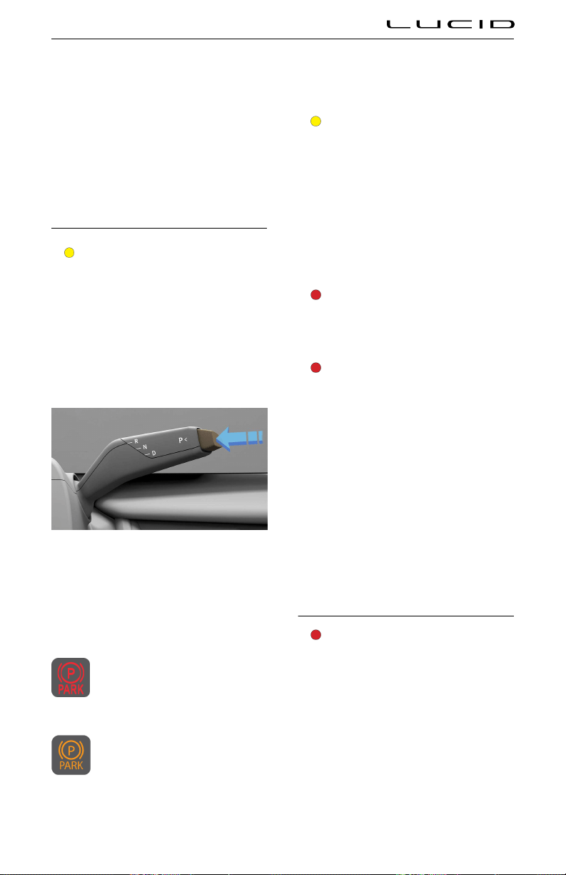
Note: Stop Mode disengages if the driver shifts
into N (Neutral) or presses and releases the
brake pedal.
Note: Stop Mode will disengage and shift into
P (Park) in any of the following instances:
- Stop Mode has been actively braking for
approximately 10 minutes.
- The system detects that the driver has
exited the vehicle.
Parking Brake
CAUTION: In the unlikely event that
your vehicle loses electrical power, you
will not be able to select another gear
and therefore will be unable to release
the parking brake. Contact a Lucid
Service Center for assistance.
The parking brake operates on the rear wheels
only, and is independently controlled of the
pedal-operated brake system.
The parking brake automatically applies when P
(Park) is selected, and releases when any other
gear is selected.
It may also be engaged by certain systems
when a set time limit is reached, such as
Stopping Mode. See Stop Mode on page 81.
The red parking brake indicator is
displayed on the Instrument Cluster
whenever the parking brake is
engaged or when the parking brake
has not completed its operation properly.
If the indicator is amber, a fault
has been detected and the parking
brake may not be applied when
the vehicle is in
P (Park). This will
be accompanied by a notification on the
Instrument Cluster. Contact a Lucid Service
Center to have the fault repaired.
Emergency use
CAUTION: Driving the vehicle with the
parking brake applied, or repeated use
of the parking brake to slow the vehicle,
may cause serious damage to the brake
system.
In an emergency, pressing and holding the P
(Park) button decelerates the vehicle to a low
speed using the service brakes, then applies
the parking brake.
Parking on a slope
WARNING: In snowy or icy conditions,
the rear wheels may not have sufficient
traction to prevent the vehicle from
sliding when parked on a slope. You are
always responsible for parking safely.
WARNING: If parking on too steep a
grade for the parking brake to securely
hold the vehicle, the vehicle will give
audible and visual warnings. Drive to a
less steep area and re-park.
As an added precaution:
- If your vehicle is parked on a hill and
facing uphill, turn the steering wheel so
the front wheels are pointing away from
the curb.
- If your vehicle is parked on a hill and
facing downhill, turn the steering wheel
so the front wheels are pointing towards
the curb.
Brake Pad Wear
WARNING: Neglecting to replace worn
brake pads can damage the brake
rotors, reduce the vehicle’s braking
efficiency, and increase the distance
needed to stop the car.
The brake pads installed on your vehicle are
equipped with wear indicators, which will cause
the vehicle to display warning messages when
the brake pads are nearing end of life. To
replace the brake pads, contact authorized
Lucid Motors Service Center.
Driving & Operating 82

If the red brake wear indicator
displays on the Instrument Cluster,
the system has detected excessive
brake wear. Contact a Lucid Service
Center as soon as possible to have the brakes
inspected.
Driving & Operating 83

Lucid Stability Control
Lucid Stability Control
WARNING: No electronic system can
remove the need for safe driving
practices. Although the Lucid Stability
Control system can help to maintain
control of the vehicle under certain
driving conditions, it cannot prevent
any accident which may occur due to
unforeseen road conditions (e.g, black
ice, standing water) or result from
careless/dangerous driving techniques.
The Lucid Stability Control system uses
multiple sensors to monitor driver inputs
and vehicle motion. Under certain driving
conditions, the system helps to perform the
following functions:
- Controls brake pressure to reduce wheel
slip on one slipping drive wheel so power
is transferred to a drive wheel on the
same axle that is not slipping.
- Controls brake pressure and traction
motor output to reduce drive wheel slip.
Controls brake pressure at individual
wheels and traction motor output to help
the driver maintain control of the vehicle
in the following conditions:
○ Under-steering, sometimes called
"washout." When the front wheels
are turned and the vehicle does
not respond but continues straight,
causing the front tires to lose
traction.
○ Over-steering, sometimes called
"fishtailing." When the rear tire loses
traction during a turn and cases the
rear of the car to swing out further
than intended.
If the Lucid Stability Control system
activates while driving,or a fault is
detected, the indicator will flash on
the Instrument Cluster.
Lucid Stability Control settings
On the Pilot Panel, press
> Vehicle
> Drive Settings, then press to select between
three levels of Lucid Stability Control:
- Full - This setting is recommended for
most driving conditions.
- Partial - Provides a more dynamic driving
experience. Not available in "Smooth"
mode.
- Off - Disabling stability control
significantly reduces traction control and
should only be disabled by advanced
drivers on closed courses. Not available
in "Smooth" mode.
Note: You will be prompted to confirm
your selection before turning Lucid Stability
ControlOff.
If the Lucid Stability Control system
is disabled or a fault is detected,
the indicator will illuminate on the
Instrument Cluster throughout the
drive cycle.
Note: This setting defaults to FULL for each
new key cycle.
Driving & Operating 84

Getting Maximum Range
Driving Tips to Maximize Range
- Remove any unnecessary cargo to reduce
vehicle load weight.
- Ensure your tires are maintained at
their specified inflation pressures. See
Maintaining Tire Pressures.
- Keep all windows closed when possible to
reduce drag.
- Avoid abrupt and/or frequent
acceleration. Try to maintain an even
speed.
- When it is safe to do so, use one
pedal driving techniques to gradually slow
the vehicle using regenerative braking
rather than friction braking. See Braking
Systems on page 80.
- Switch into Smooth mode. See Drive
Modes on page 73.
- Limit the use of the heating and air
conditioning controls when possible.
Using seat heaters to keep warm is
a more energy-efficient alternative than
heating the entire cabin.
Driving & Operating 85

Heating, Ventilation Air Conditioning
Temperature Control
Cabin heating, ventilation, and air conditioning
is divided into four zones: The driver and
passenger side in front, and the left and right
sides in the rear.
These zones can be adjusted simultaneously or
individually by using the Pilot Panel, the Rear
Center Console Display, or the buttons on the
dash.
Pilot Panel climate controls
On the bottom of the Pilot Panel, press
.
Press FRONT or REAR to access the controls
for those zones.
Use the sliding bar to adjust temperature and
fan speed for that zone. Slide the bar all the
way down to turn the fan Off.
This turns all controls for all four zones On or
O. For REA controls, this turns all controls
for the two rear zones On or O.
Press to turn air conditioning On or O.
Press to switch between air circulation modes.
Cabin air can be continuously recirculated, or
a blend of fresh and cool air can be drawn from
outside.
Note: Avoid recirculating cool interior air
for extended periods, as this can fog up the
windows.
Front windshield defrost. See Windshield
Defrost.
Rear defrost and side-view mirrors. See Rear
Window Defrost.
Activating this feature maintains the current
cabin temperature after exiting the vehicle for
45 minutes.
Note: You will be prompted to conirm your
selection.
Note: This feature automatically disables
when the battery drops below 50 miles
(80 kilometers) of range.
Press to open the Settings menu. From this
menu, auto-conditioning the seats and steering
wheel can be toggled On or O.
When this feature is On, zone fan speed and
vent modes are both automated by the system
based on the set temperature.
When SYNC is activated, all climate control
states are synchronized with the driver zone
(temperature value, fan speed value, and vent
modes).
Note: If a passenger adjusts a control while
SYNC is On, this turns SYNC O. The control
states for the remaining zones stay as they were
previously set while in SYNC.
Press an icon to turn the fan for that area
On or O. Multiple areas can be selected
simultaneously.
Front temperature control buttons
The buttons on the dash can be used to adjust
the temperature and fan speed for the driver
and front passenger.
Driving & Operating 86

Move a button up or down once to change
the temperature or fan speed by ±1 increment.
Press and hold the tole to raise or lower by
multiple increments.
When the temperature control buttons are
used, the right Cockpit Panel will open a small
Peek window along the bottom of the display.
This window displays the current temperature
and fan settings, and will update according to
the control interactions. Any settings actively
being changed are highlighted.
Note: The Peek window automatically
disappears after a few seconds of inactivity.
Touch or swipe anywhere on the Peek window
to dismiss it sooner.
Rear Center Console Display
From the main menu, select Climate to access
the controls for the rear zones. To return to the
main menu, press on the bottom bar and swipe
up.
Press an arrow once to change the temperature
or fan speed by ±1 increment. Press and hold
adjust by multiple increments.
Note: When the system does not detect any
passengers in the rear seats, climate controls
are automatically turned Off.
Preconditioning
Preconditioning is available within the Lucid
mobile app, allowing you to remotely set the
cabin temperature or windshield defrosting
controls.
Note: When preconditioning is activated, any
changes to the temperature controls via the
Pilot Panel will cancel the feature.
Defrost
Windshield defrost
To defrost the windshield, press the
icon on the left Cockpit Panel or from
the
screen on the Pilot Panel. The
icon will highlight when activated.
Once pressed, heat and fan speed will switch
to high settings, and air flow will be directed
through the vents at the base of the windshield.
Note: When front defrost is activated, any
changes to the temperature controls via the
Pilot Panel will cancel the feature.
Rear window defrost
To activate the rear window defroster,
press the icon on the left Cockpit
Panel or from the
screen on the
Pilot Panel. The icon will highlight
when activated.
After approximately 15 minutes, the defroster
will automatically turn off.
Driving & Operating 87
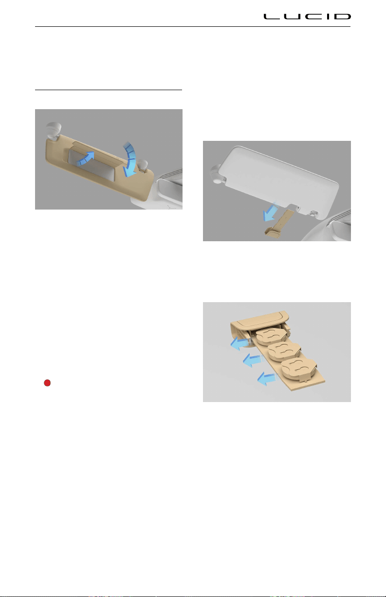
Interior Equipment
Sun Visors
To use a sun visor, fold it down from its stowed
position.
For your convenience, the sun visor can also be
pivoted towards the side window by releasing it
from the retaining clip (arrowed).
Note: Make sure the sun visor is secured by
the retaining clip when returning it to its stowed
position.
Both sun visors have a covered mirror. Raise
the cover to use the mirror; an integrated light
automatically turns On. The light turns Off
when the cover is closed.
Sun visor battery replacement
WARNING: Each sun visor contains
three coin/button type batteries. These
batteries contain toxic and corrosive
substances.Batteries are a chemical
burn hazard and should never be
ingested. If a battery is swallowed, it
can cause serious internal burns and
may even lead to death.
- Keep new and used batteries out of
the reach of children.
- If you think batteries may have been
swallowed or placed inside any part
of the body, seek immediate medical
attention.
Due to the unique design of your vehicle, the
sun visors use batteries to power the mirror
lights.
Note: The batteries have an estimated life
of approximately two years based on typical
usage.
To replace the batteries:
With the sun visor in its stowed position, slide
the battery holder towards the front of the
vehicle.
Remove the old batteries.
Install new batteries and avoid touching the
flat surfaces of the batteries if possible, as
finger marks can reduce battery life. Wipe
the batteries clean before installation. Fit the
battery with the “+” side facing upwards.
Note: Always replace all three batteries with
new CR2032 batteries.
Reinstall the battery holder in the sun visor.
Driving & Operating 88

Glove Box
The glove box is opened using the Pilot Panel.
Select
> GLOVEBOX.
To close, push the glove box cover until it
latches.
Front Armrest and Storage Compartment
WARNING: Do not operate the vehicle
with the storage compartment lid in the
open position as this could result in
injury in a collision.
Slide the cover to access the front cup holders
and storage area.
Pull the release latch and lift up the armrest to
access the storage compartment.
Center Console Storage Compartment
Pull the latch to release the storage
compartment cover and allow it to open. Press
the cover to close.
Rear Armrest and Storage Compartment
WARNING: The rear armrest must not
be used as a seat or a booster cushion
for small children. Children must be
seated in a seat suitable for their size
and weight to reduce the risk of injury
in a crash. See Guidelines for Seating
Children on page 48
Use the latch to pull down the rear center
armrest.
Driving & Operating 89

Pull up on the lid to access the storage
compartment. Close the lid and push the
armrest up to close.
Cup Holders
Note: The cup holders have a rubber insert that
can be removed to allow them to be cleaned if
there is a spillage.
Cup holders are located in the following
locations:
Front center console. Slide the cover rearwards
to use the cup holder.
Rear arm rest. Fold down the rear armrest.
Driving & Operating 90

Accessory Connections
USB Connections
USB-C ports for charging mobile devices can
be found in the following areas:
Two in the storage compartment of the front
center console.
Two on the rear of the front center console.
Note: Do not connect multiple devices to the
USB ports using a USB hub. This may overload
the USB charging circuit and prevent some
devices from charging.
Wireless Charging
A wireless charging pad is located in the center
console storage compartment.
To charge a mobile phone with wireless
charging capability, insert the phone in to the
left clip with the back of the phone in contact
with the side of the storage compartment.
FCC Notes
This device complies with part 15 of the
FCC Rules. Operation is subject to the
following two conditions: (1) This device
may not cause harmful interference, and (2)
this device must accept any interference
received, including interference that may cause
undesired operation.
Changes or modifications not expressly
approved by the party responsible for
compliance could void the user's authority to
operate the equipment.
This equipment has been tested and found
to comply with the limits for a Class B
digital device, pursuant to part 15 of the
FCC Rules. These limits are designed to
provide reasonable protection against harmful
interference in a residential installation.
This equipment generates, uses and can
radiate radio frequency energy and, if not
installed and used in accordance with the
instructions, may cause harmful interference
to radio communications. However, there is
no guarantee that interference will not occur
in a particular installation. If this equipment
does cause harmful interference to radio or
television reception, which can be determined
by turning the equipment off and on, the user is
Driving & Operating 91
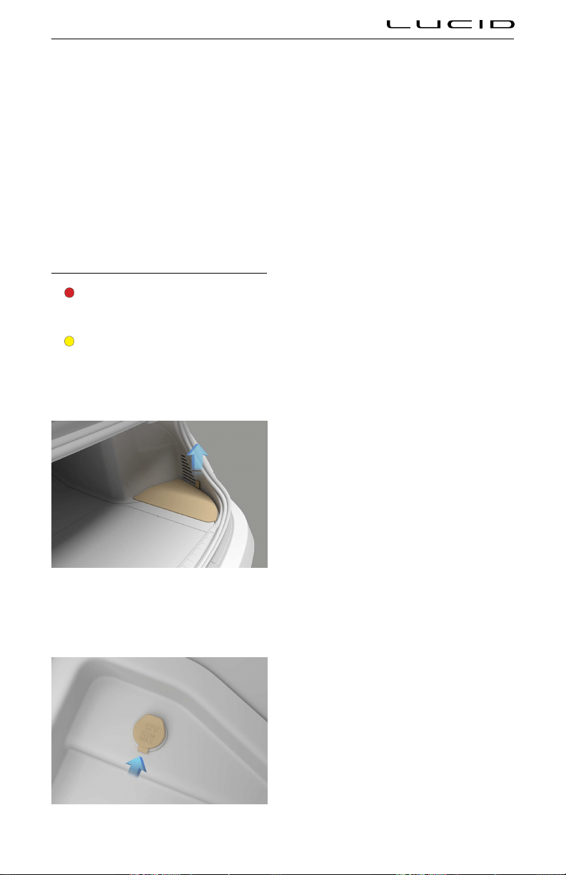
encouraged to try to correct the interference by
one or more of the following measures:
- Reorient or relocate the receiving
antenna.
- Increase the separation between the
equipment and receiver.
- Connect the equipment into an outlet on
a circuit different from that to which the
receiver is connected.
- Consult the dealer or an experienced
radio/TV technician for help.
12 Volt Power Socket
WARNING: Close the cover when not in
use. If this outlet is mishandled, it may
cause an electric shock.
CAUTION: The 12 Volt power socket
should not be used with a cigarette
lighter. Lighters could potentially cause
heat damage to the socket.
A 12 Volt power socket is located in the trunk.
Remove the RH floor panel to access the power
socket.
Although the power socket is primarily provided
for use with the tire repair kit, it can also be
used for other accessories requiring up to 15A
or a maximum of 180 watts.
Driving & Operating 92

About ADAS
ADAS Limitations
WARNING: This manual does not
include all of the situations that might
interfere with the proper operation
of ADAS components. Never rely on
these components to keep you or
your occupants safe. It is the driver’s
responsibility to remain alert and drive
safely and responsibly at all times.
CAUTION: Lucid strongly recommends
always having your vehicle serviced at
a Lucid Service Center to ensure all
of the vehicle’s ADAS components are
handled properly. Failure to do so can
cause one or more ADAS features to
malfunction.
CAUTION: If a fault occurs with any
of the ADAS features, contact a Lucid
Service Center.
There are numerous factors that can impact the
performance of the ADAS components, causing
them to be unable to function as intended.
These factors include (but are not limited to):
- Poor sensor visibility due to weather
conditions (e.g., heavy rain, snow, or fog)
- Bright ambient light (e.g., oncoming
headlights or direct sunlight)
- Poor ambient light (e.g., at night or in
poorly-lit tunnels)
- If the sensors, cameras, or the camera
view areas of the glass canopy become
dirty, foy, damaged, or otherwise
obscured
- Interference or obstruction by an object
mounted onto the vehicle (such as a bike
rack)
- Obstruction caused by applying excessive
paint or adhesive products (e.g., wraps,
stickers, or rubber coatings) onto the
vehicle
- Narrow or winding roads
- A damaged or misaligned bumper
- Interference from other equipment that
generates ultrasonic waves
- Extremely hot or cold temperatures
- Lucid Stability Control is partially or
completely disabled
- Selecting 'Sprint' driving mode
Sensor and camera failure
CAUTION: If blockage occurs with an
ADAS sensor, attempt to clear the
blockage. Remove any objects that
may be obstructing the component, or
clean off any debris by following the
cleaning instructions in this document.
See ADAS Limitations. If the warning
message persists, contact a Lucid
Service Center.If a sensor or camera
failure occurs (something other than
a blockage that you cannot remedy),
contact a Lucid Service Center.
When the system detects that a sensor or
camera is blocked, a warning with the location
of the blocked component displays on the
Cockpit Panel.
When an ADAS component is blocked or faulty,
any related features will be unavailable or
have degraded performance. On the Pilot Panel
under
> DreamDrive, any relevant
settings will be grayed out with a warning
message displayed.
ADAS Features
Your Lucid Air is equipped with Advanced
Driver Assistance Systems (ADAS), named
Advanced Driver Assistance Systems (ADAS) 93

Lucid DreamDrive. The following features are
available:
Driving Experience
- Adaptive Cruise Control
- Highway Assist
- Traffic Sign Recognition
- Traffic Drive-Off Alert
- High Beam Assist
- Drowsy Driver Alert
- Distracted Driver Alert
Supplemental Safety
- Forward Collision Warning
- Automatic Emergency Braking
- Cross Traffic Protection
- Lane Departure Protection
- Blind Spot Warning
- Blind Spot Display
Parking Experience
- Automatic Park In
- Automatic Park Out
- Surround View Monitoring
- Rear View Monitoring
- Park Distance Warning
The ADAS features are configured using the
Pilot Panel. To find out more about each
feature, press the 'i' icon next to the feature.
These features are designed to increase vehicle
safety and improve driving behavior. You can
enable or disable most features individually and
(in some cases) adjust operating parameters.
Driver Responsibility
ADAS systems are designed for comfort,
convenience, and to enhance safety. However,
these systems are NOT replacements for
attentive, responsible driving.
WARNING: As the driver of this
vehicle, you are responsible for its
safe operation. You myst be observent
of, and address, any warnings and
indications of unsafe conditions caused
by the vehicle of external factors.
Brake or steering interventions only take place
within defined limits, and may not have time
to slow or correct the vehicle enough to avoid
a collision. Your complete attention is still
required while driving, and you should always
be ready to steer the vehicle and apply the
brakes when necessary.
Advanced Driver Assistance Systems (ADAS) 94


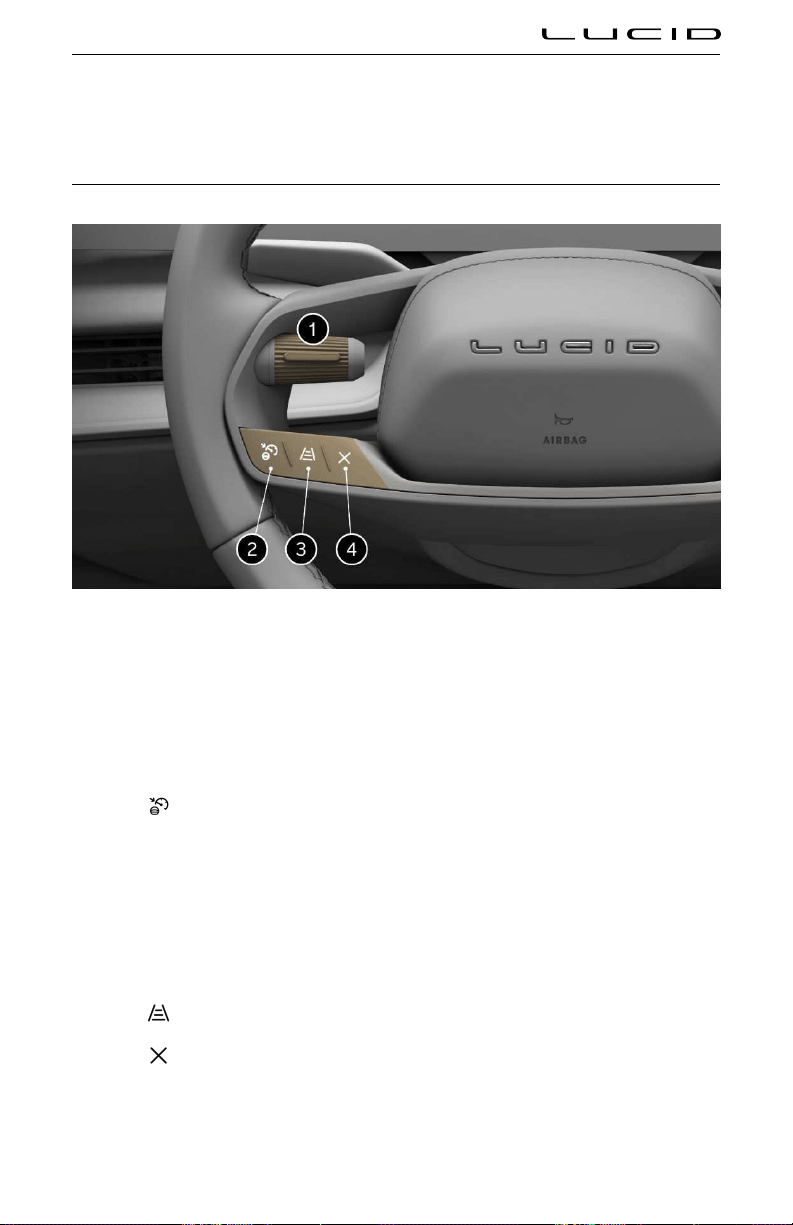
DreamDrive
Steering Wheel DreamDrive Controls
1. Tole switch
2. DreamDrive activate
3. Gap Setting adjustment
4. Cancel Drive Assist control
Using DreamDrive
- Press
to access or exit DreamDrive mode.
- Press and hold to switch between Adaptive Cruise Control and Highway Assist systems (see
Adaptive Cruise Control and Highway Assist).
- Press the tole button to engage the feature.
- Push the tole up/down to adjust the set speed by ±1 increment.
Push and hold the tole up/down to adjust the set speed by ±5 increments.
- Press to adjust the gap setting (see Adjusting following distance).
- Press
to cancel Adaptive Cruise Control or Highway Assist.
Advanced Driver Assistance Systems (ADAS) 97

DreamDrive Requirements
Adaptive Cruise Control or Highway Assist
can be activated when all of the following
conditions are met:
- Driver’s seat belt is buckled
- All doors are closed
- Vehicle is in
D (Drive)
- Brake pedal is released
- Current speed is at least 20 mph
(30 km/h)
Adaptive Cruise Control and Highway Assist
will automatically disengage and sound an
audible alert in any of the following situations:
- Brake pedal is pressed
- Driver’s seat belt is unbuckled
- The trunk, the hood, or a door is open
- Gear is shifted out of
D (Drive)
- The parking brake is applied (see
Parking
Brake)
- Vehicle speed goes above the maximum
threshold of 90 mph (150 km/h)
- The tires lose traction
- Automatic Emergency Braking is activated
(see
Automatic Emergency Braking)
- A system feature fails (such as a
powertrain or sensor failure)
- Front camera is blocked
Note: If the system notes that the front
camera is blocked, try activating the
wipers. See Wipers.
- Brake temperature is too high
Adaptive Cruise Control and Highway Assist
systems, even under optimal conditions, are
not a substitute for safe driving. See ADAS
Limitations for details.
Adaptive Cruise Control
WARNING: Adaptive Cruise Control is
designed for your driving comfort and
convenience and is not a collision
warning or avoidance system. It is your
responsibility to stay alert, drive safely,
and be in control of the vehicle at
all times. Never depend on Adaptive
Cruise Control to adequately slow down
the vehicle. Watch the road in front of
you and be prepared to take corrective
action at all times. Failure to do so can
result in serious injury or death.
WARNING: Never depend on Adaptive
Cruise Control to brake for pedestrians,
animals, or other objects. Always watch
the road and be prepared to take
corrective action. Failure to do so can
result in serious injury or death.
WARNING: Do not use Adaptive Cruise
Control on city streets or on roads
where traffic conditions are constantly
changing.
WARNING: Adaptive Cruise Control
may not detect or brake for
narrow vehicles such as bicycles or
motorcycles.
WARNING: Adaptive Cruise Control
may not detect stationary or slow
moving vehicles below 6 mph (10 km/h).
WARNING: Do not use Adaptive Cruise
Control on winding roads with sharp
curves, on icy or slippery road surfaces,
or when weather conditions (e.g., heavy
rain, snow, or fog) make it inappropriate
to drive at a consistent speed. Adaptive
Cruise Control does not adapt driving
speed based on road and driving
conditions.
WARNING: Turn Adaptive Cruise
Control off temporarily when driving in
areas where you must reduce speed
(e.g., turn lanes, entering and exiting
highways, or construction zones). This
prevents the vehicle from accelerating
to the stored speed in such situations.
When engaged, Adaptive Cruise Control uses
data from the vehicle’s exterior sensors to
automatically adjust your cruising speed,
maintaining a safe distance from any vehicles
ahead. The default distance maintained is the
furthest allowed. See <<adjusting following
distance >>
Advanced Driver Assistance Systems (ADAS) 98

Adaptive Cruise Control is primarily intended
for driving on dry, straight roads with no
stops or sharp curves, such as highways and
freeways.
If the adaptive Cruise Control cannot brake the
vehicle safely, it will issue a takeover request.
Note: If your vehicle stops behind another
vehicle and remains stationary for more than
10 minutes while Adaptive Cruise Control is
active, the system will disengage and apply the
Emergency Parking Brake (EPB).
Setting and changing cruising speed
To activate Adaptive Cruise Control, press the
DreamDrive button on the steering wheel.
See Steering Wheel DreamDrive Controls.
Note: The DreamDrive mode defaults to
Highway Assist for first-time users. When a
User Profile is active, the system will go to the
last used DreamDrive mode (Adaptive Cruise
Control or Highway Assist). If Highway Assist is
activated, press and hold the
. DreamDrive
button to switch to Adaptive Cruise Control.
To set the cruising speed:
- Push the left tole up or down to adjust
speed by ±1 increment.
- Push and hold the left tole up or down
to adjust the set speed by ±5 increments.
Minimum speed: 20 mph (30 km/h)
Maximum speed: 90 mph (150 km/h)
The cruising speed displays to the right of
the speedometer on the Cockpit Panel, and is
highlighted when Adaptive Cruise Control is
active. Once activated, cruising speed can be
changed using the same controls.
Cruising speed
WARNING: Occasionally, Adaptive
Cruise Control may brake late or
unexpectedly due to following a vehicle
too closely, or if detection issues
occur due to road infrastructure (e.g.,
curves, bridges, or tunnels). At all times,
the driver is responsible for watching
the road, controlling the vehicle, and
intervening if required.
Adaptive Cruise Control maintains your
selected cruising speed when a vehicle is not
detected in front of you.
When cruising behind a detected vehicle,
highlighted in the instrument cluster, Adaptive
Cruise Control accelerates and decelerates the
vehicle as needed to maintain the set following
distance up to the set speed. See Adjusting
following distance.
Adopting new speed limits
When Cruise Speed Update is enabled, the
system will prompt you on the Instrument
Cluster when a new speed limit is detected.
Press the left tole button on the steering
wheel to update the cruising speed to the new
speed limit.
If you do not wish to update the cruising speed,
the prompt will disappear after 7 seconds.
Note: If you do not wish to receive prompts
regarding speed limit changes from Cruise
Speed Update, they can be disabled.
Driver override
WARNING: During driver override,
Adaptive Cruise Control will not apply
the brakes to maintain the set following
distance from a vehicle ahead.
While Adaptive Cruise Control is active, you
can temporarily override the set speed using
the accelerator pedal. If the Adaptive Crusie
Control is overridden for more than 60 seconds,
it will disengage.
When you press the accelerator pedal, the
Center Cockpit Panel displays the following:
- ADAPTIVE CRUISE display will change to
OVERRIDE
- Lane display, highlighted when Adaptive
Cruise Control is active, will no longer be
highlighted
- The target vehicle will not be highlighted
Advanced Driver Assistance Systems (ADAS) 99

Once the accelerator is released, Adaptive
Cruise Control should automatically resume
and return to the cruise speed set by the driver.
The Instrument Cluster displays the active
Adaptive Cruise Control mode.
Adjusting following distance
WARNING: It is your responsibility as
the driver to determine and maintain
a safe following distance at all times.
Do not rely on Adaptive Cruise Control
to maintain an accurate or appropriate
following distance.
WARNING: Never depend on Adaptive
Cruise Control to adequately slow down
the vehicle to avoid a collision. Always
watch the road in front of you and be
prepared to take corrective action at all
times. Failure to do so can result in a
collision with the risk of serious injury
or death.
To adjust the vehicle’s time gap settings from
the vehicle ahead, press the
button on the
steering wheel. See Steering Wheel DreamDrive
Controls. There are four time gap settings to
select from, which will cycle as the
button
is pressed.
The change in the time gap settingse will be
shown on the Instrument Cluster.
Cancel and resume cruise control
To cancel Adaptive Cruise Control, press the
Cancel button on the steering wheel. See
Steering Wheel DreamDrive Controls.
The system can also be canceled by pressing
the brake pedal if it is safe to do so in the
current traffic conditions.
After Adaptive Cruise Control has been
canceled, you can resume the previously set
speed by toling up the left steering wheel
control.
Highway Assist
Highway Assist system detects lane markings
and the presence of other vehicles to help keep
the vehicle centered in a lane while maintaining
the set speed and the following distance.
WARNING: Highway Assist is designed
for your driving comfort and
convenience and is not a collision
warning or avoidance system. It is your
responsibility to stay alert, drive safely,
and be in control of the vehicle at all
times.
WARNING: Never depend on Highway
Assist to adequately steer the vehicle.
Always keep your hands on the steering
wheel, watch the road in front of you,
and be prepared to take corrective
action. Failure to do so can result in
serious injury or death.
WARNING: Detection of lane markings
and objects may malfunction, causing
Highway Assist to make unexpected
steering interventions. If this happens,
then driver is responsible to steer
according to traffic conditions.
Note: If Highway Assist is activated, Lane
Departure Protection is automatically activated.
Activating Highway Assist
To activate Highway Assist, press the
DreamDrive button on the steering
wheel. Press the tole button to set desired
cruise speed. See Steering Wheel DreamDrive
Controls.
Note: The DreamDrive mode defaults to
Highway Assist for first-time users. When a
User Profile is active, the system will go
to the last used DreamDrive mode (Adaptive
Cruise Control or Highway Assist). If Adaptive
Cruise Control is activated, press and hold the
DreamDrive button to switch to Highway
Assist.
When Highway Assist is activated, the
lane is highlighted, and an indicator
displays on the Instrument Cluster.
Note: When Highway Assist has been
temporarily overridden, this indicator and lane
highlighting will gray out. Also, the text will
change to "Override".
Advanced Driver Assistance Systems (ADAS) 100
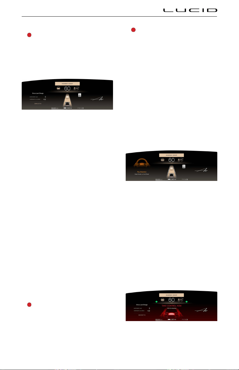
Traffic Jam Assist
WARNING: When Traffic Jam Assist is
following a leading vehicle and no lanes
are detected, your vehicle may follow
the lead vehicle into another lane. It is
your responsibility to stay aware of your
surroundings and be prepared to take
corrective action at all times.
The image above displays lane control. When
the system cannot detect the lane lines or lane
markings and there is a vehicle ahead, Highway
Assist will follow the leading vehicle.
Note: Traffic Jam Assist is only available when
the vehicle’s speed is under 43 mph (70 km/h).
When lanes are detected, the system prioritizes
using the lanes over following a leading vehicle.
Cooperative lane changing
To change lanes without disengaging or
deactivating Highway Assist, activate the turn
signal in the direction you will be changing
lanes. See Turn Signals.
When you turn on the turn signal, Highway
Assist will be temporarily overridden, allowing
you to manually complete the lane change.
When the vehicle is centered in the new lane
and both lane lines are detected, Highway
Assist will automatically resume.
When you turn on the turn signal:
- The Highway Assist indicator will gray out
- The lane will not be highlighted
- Any target vehicle will not be highlighted
Hands-off detection and in-lane stops
WARNING: An in-lane stop is illegal
in many areas. It is an emergency
procedure only and should not be
misused. Do not deliberately initiate an
in-lane stop as a means to stop the
vehicle.
WARNING: An in-lane stop is meant
to reduce the hazard of a moving
vehicle that is not being consistently
controlled by the driver. However, a
vehicle stopped in traffic can also be a
hazard.
While Highway Assist helps you with steering,
it's still necessary to keep your hands on the
wheel and pay attention to the road at all
times. If the system detects that the driver is
distracted and their hands are no longer on
the steering wheel, it will provide a series of
warnings which, if not attended to, will lead to
an in-lane stop.
If Highway Assist detects that the driver is
distracted (not looking forward and their hands
are not on the steering wheel) for longer
than 6 seconds, a prompt will display on the
Instrument Cluster.
If no steering wheel input has been detected
for 15 seconds a warning will display on the
Instrument Cluster, prompting the driver to put
their hands on the steering wheel.
If still no steering wheel input has been
detected after an additional 15 seconds:
- An elevated warning appears on the
Instrument Cluster, prompting the driver
to put their hands on the steering wheel.
- An alert sounds.
- The driver receives haptic brake feedback
before in-lane stop deceleration begins.
The final stage of in-stop initiation depends
upon the current speed of the vehicle, and will
occur any time after 33 seconds of continuous
Advanced Driver Assistance Systems (ADAS) 101

detection that the driver’s hands are off the
steering wheel:
- The vehicle will gradually slow based
upon the current speed.
- Hazard lights will activate.
- A flashing red animation will appear on
the Instrument Cluster.
- Audible warnings will sound.
Note: If the driver provides steering wheel
input, or presses either the brake or accelerator
during an in-lane stop, the system cancels the
in-lane stop. If the vehicle has already started
to slow down, DreamDrive will be unavailable
until the next drive cycle.
Once an in-lane stop has completed:
- The vehicle automatically shifts into
P
(Park).
- Highway Assist is canceled.
- DreamDrive will be unavailable until the
next drive cycle.
- All doors unlock.
- An audible alert sounds.
Note: Warnings will be dismissed if the vehicle
is shifted out of
P (Park). See Selecting a Drive
Mode.
Steering override
While Highway Assist is active, you can
temporarily override it by using the steering
wheel. When you turn the steering wheel, the
Highway Assist indicator will gray out on the
Instrument Cluster.
Once the steering wheel returns to its neutral
position, the vehicle is centered in the lane,
and the system detects lanes again, Highway
Assist should automatically resume and the
Instrument Cluster will return to displaying the
active Highway Assist mode.
Manually canceling Highway Assist
To cancel Highway Assist, press the
Cancel
button on the steering wheel. See Steering
Wheel DreamDrive Controls.
The system can also be canceled by pressing
the brake pedal if it is safe to do so in the
current traffic conditions.
Traffic Sign Recognition
WARNING: Traffic Sign Recognition
is an assist feature only. The driver
is responsible for paying attention
to the road signs and determining
the appropriate speed limit, road
conditions, and driving speed.
WARNING: Traffic Sign Recognition is
not available in all countries.
WARNING: Map data is not always
accurate. The GPS can miscalculate the
vehicle location, which may provide an
incorrect traffic sign.
WARNING: If a road or a traffic sign has
recently been changed, the Traffic Sign
Recognition system may not be fully
functional or may provide inaccurate
information.
WARNING: In situations where the
Traffic Sign Recognition system is
unable to determine a traffic sign, or if
it is uncertain that an acquired speed
limit is accurate, the system may not
display the information and warnings
may not take effect.
The Traffic Sign Recognition system uses the
front cameras and navigation system data to
recognize traffic signs on the road, providing
you with driving information such as speed
limits and other regulations.
When a traffic sign is detected, it displays
on the Instrument Cluster next to the
speedometer.
In addition to the current speed limit, any
upcoming speed limit is displayed behind the
current one when the system detects a new
sign. If the speed limit is not detected a blank
speed limit sign is displayed.
Advanced Driver Assistance Systems (ADAS) 102

Speed Limit Alerts
When Speed Limit Alert is enabled (see Speed
Limit Alert settings), if the current vehicle
speed exceeds the detected speed limit, the
display color of the speed limit sign will change
color and may increase in size. The display will
return to the normal color and size when the
vehicle is slowed to within the speed limit.
Wrong-way warnings
If a Wrong Way road sign is detected and the
vehicle passes the sign, the system will alert
you with an audible alert and a notification on
the Instrument Cluster.
Speed Limit Alert settings
To configure Speed Limit Alert settings, use the
Pilot Panel and touch
> DreamDrive.
- Touch to enable or disable Speed
Limit Alert. Additional options to receive
VISUAL or VISUAL AND AUDIO alerts are
available when this feature is enabled.
- Touch to enable or disable
Cruise Speed
Update. When enabled, this feature
notifies you when a new speed limit is
detected and prompts you with an option
to update your cruising speed when
Adaptive Cruise Control is active. It is the
driver's responsibility to determine the
appropriate speed limit, road conditions,
and driving speed. See
Adopting new
speed limits.
Note: When this feature is disabled, the
detected speed limit will still be displayed
next to the set cruise speed on the
Instrument Cluster.
Traffic Drive-Off Alert
WARNING: Never assume it is safe
or legal to proceed when Traffic Drive-
Off Alert activates. Always check your
surroundings first.
When your vehicle comes to a stop behind
traffic (or another stopped vehicle), the Traffic
Drive-Off Alert system monitors the driver and
alerts them it they are distracted when the front
vehicle pulls away from a stopped position.
If a stopped vehicle in front pulls away, the
system provides audible and visual alerts if the
interior camera detects that you are not facing
forward.
Note: If the interior camera detects that you
are already facing forward, you will not receive
Traffic Drive-Off Alerts.
When Adaptive Cruise Control is active (see
Adaptive Cruise Control) and the vehicle is
stopped, you will receive a prompt on the
Instrument Cluster once the traffic ahead
clears. You can resume cruising speed by
pressing the accelerator, or by pushing up on
the left steering wheel tole (see Steering
Wheel DreamDrive Controls).
If you do not react to the initial prompt within
a few seconds, the prompt will change and the
system will sound an audible alert if the driver
is distracted.
Traffic Drive-Off Alert settings
To configure Traffic Drive-Off Alert settings,
use the Pilot Panel and touch
>
DreamDrive, then press to enable or
disable Traffic Drive-Off Alert.
Note: The Traffic Drive-Off Alert setting will be
saved to the current active User Profile, and will
not reset at each drive cycle.
Advanced Driver Assistance Systems (ADAS) 103
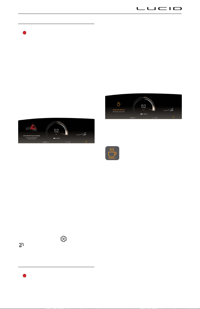
Distracted Driver Alert
WARNING: Do not rely on the
Distracted Driver Alert to maintain
your focus on the road. The driver is
responsible for paying attention at all
times while operating the vehicle.
When enabled, the Distracted Driver Alert
system will monitor the driver via the interior
camera, and issue alerts when it detects that
the driver’s eyes are not on the road. See
Interior Camera.
Note: In some circumstances the interior
camera might be blocked. In this case, both
the distracted driver and drowsy driver alerts
will be unavailable. In this case an alert will
appear on the center cockpit panel. When the
obstruction is removed, driver will be notified.
Note: Distracted Driver Alert is not available
when the vehicle’s speed is below 25 mph
(40 km/h).
If the system detects that the driver’s eyes are
off the road for 2 seconds, an alert will display
on the Instrument Cluster and a chime will
sound.
If the system detects that the driver has their
eyes off the road for an additional 3-5 seconds,
a warning will display on the Instrument
Cluster. A chime will sound and a haptic pulse
will vibrate the steering wheel to alert the
driver.
Distracted Driver Alert settings
To configure Distracted Driver Alert settings,
from the Pilot Panel touch
>
DreamDrive, then enable or disable
Distraction Alert. Distraction settings save to
the current User Profile.
Drowsy Driver Alert
WARNING: Do not rely on the Drowsy
Driver Alert to warn you when you are
not focusing on the road or driving
erratically. Drive to a safe area and park
when you're unable to focus on driving.
When enabled, the Drowsy Driver Alert system
issues alerts when it detects early signs
of drowsiness. This system monitors for the
following signs:
- Frequent driver eye closure (detected via
the interior camera)
- Erratic driving behavior (such as swerving)
Note: Drowsy Driver Alert is not available when
the vehicle’s speed is below 25 mph (40 km/h).
If the system detects signs of driver drowsiness,
a notification will appear on the Instrument
Cluster.
When Drowsy Driver Alert activates,
an indicator displays on the
Instrument Cluster until the vehicle
has been stopped or shifted out of
D (Drive).
In addition to the alert, the right Cockpit Panel
will display a list of nearby break areas when
available. If desired, press a location to add a
waypoint to your current trip and navigate to
that break area. See Navigating.
If the system detects continued signs of
drowsiness after the first alert, a warning
notification appears on the Instrument Cluster
and an audible alert sounds.
In addition to the alerts, the right Cockpit Panel
displays a list of nearby break areas when
available. Press SHOW ME to view the list, or
DISMISS to clear.
If the system still detects signs of drowsiness
after the second alert, a new warning
notification appears in addition to a louder
audible alert and haptic vibration of the
steering wheel. Hazard lights are activated. The
right Cockpit Panel again displays a list of
nearby break areas.
Responses include:
Advanced Driver Assistance Systems (ADAS) 104

- Pressing a selection in the prompt on the
right Cockpit Panel
- Double-clicking the Hazard Light button
- Stopping the vehicle
- Shifting out of
D (Drive)
Drowsy Driver Alert settings
On the Pilot Panel, press >
DreamDrive, then press to enable or
disable Drowsy Driver Alert. Drowsy Driver
settings save to the current User Profile
Advanced Driver Assistance Systems (ADAS) 105

Collision Protection
Forward Collision Warning
WARNING: Forward Collision Warning
is an assist feature only, and is
not a substitute for attentive driving
and sound judgment. The driver is
responsible for paying attention to the
road, maintaining a suitable distance
from the vehicle ahead, and braking or
steering the vehicle when necessary.
WARNING: There are factors that can
reduce or impair the performance of
the Forward Collision Warning system,
causing either unnecessary, invalid,
inaccurate, or missed warnings. Do
not rely solely on Forward Collision
Warning to warn you of a potential
collision.
WARNING: Forward Collision Warning
only monitors what is in front of the
vehicle. Be aware of your surroundings
at all times while operating the vehicle.
WARNING: Forward Collision Warning
does not provide alerts when the driver
is already applying the brake.
The Forward Collision Warning system uses the
front camera mounted behind the windshield
and the radar sensor mounted behind the front
bumper to detect the presence of an object
(such as a vehicle, bicycle, or pedestrian).
If the system detects that a collision is likely
to happen, it will sound an audible alert
and prompt you to brake on the Instrument
Cluster. If this happens, TAKE IMMEDIATE
CORRECTIVE ACTION and apply the brakes or
steer clear of the impending collision.
Note: If the driver presses the brake, the system
provides additional brake support.
If you do not react sufficiently to the warning,
the Automatic Emergency Braking system
should reduce speed, which is intended to
help reduce the severity of a collision. See
Automatic Emergency Braking.
When Automatic Emergency Braking is
activated, the Instrument Cluster flashes red
and an audible alert sounds. If this happens,
TAKE IMMEDIATE CORRECTIVE ACTION.
Forward Collision Warning settings
See Automatic Emergency Braking settings.
Automatic Emergency Braking
WARNING: Automatic Emergency
Braking is not designed to prevent a
collision, but to minimize the impact
of a frontal collision by attempting to
reduce your driving speed. Depending
solely on Automatic Emergency Braking
to avoid a collision can result in serious
injury or death.
WARNING: Automatic Emergency
Braking only applies the brakes. It does
not steer the vehicle out of the path of
the hazard.
WARNING: There are factors that can
affect the performance of Automatic
Emergency Braking, causing either no
braking or inappropriate or untimely
braking. It is your responsibility to drive
safely and remain in control of the
vehicle at all times. Never depend on
Automatic Emergency Braking to avoid
or reduce the impact of a collision.
Advanced Driver Assistance Systems (ADAS) 106

WARNING: The brake pedal moves
downward abruptly during Automatic
Emergency Braking events. Always
ensure that the brake pedal can move
freely. Do not place material (including
additional mats) under or on top of the
vehicle-supplied floor mat and always
ensure that the driver's floor mat is
secured properly. Failure to do so can
impede the ability of the brake pedal to
move freely.
Working in conjunction with Forward Collision
Warning, the Automatic Emergency Braking
system detects the presence of an object such
as a vehicle, bicycle, or pedestrian. If the
system determines an imminent collision with
an object to the front it will initiate emergency
braking to reduce the severity of the impact.
If the driver presses the brake during an
Automatic Emergency Braking event, the
system will provide additional brake support.
When Automatic Emergency Braking applies
the brakes, an audible warning sounds, and
a visual warning appears on the Instrument
Cluster. You may also notice movement of the
brake pedal.
Note: If active, the Adaptive Cruise Control
and Highway Assist systems will automatically
deactivate if an Automatic Emergency Braking
event is triered. See Adaptive Cruise Control
and Highway Assist.
Note: Automatic Emergency Braking does not
apply the brakes or stops applying the brakes
when:
- Steering wheel is turned abruptly.
- Brake pedal is pressed and released while
Automatic Emergency Braking is applying
the brakes.
- Accelerator is pressed abruptly while
Automatic Emergency Braking is applying
the brakes.
- Hazard (vehicle, motorcycle, bicycle or
pedestrian) is no longer detected in the
vehicle path.
Note: Automatic Emergency Braking can be
adversely affected by the limitations of
Advanced Driver Assistance components. See
ADAS Limitations. Use appropriate caution
when driving.
If Automatic Emergency Braking is
unavailable, a warning message and
indicator display on the Instrument
Cluster. If either of these items
appear, contact a Lucid Service Center.
Automatic Emergency Braking settings
WARNING: Lucid strongly recommends
that you leave this feature enabled
to provide potential supplemental
assistance and to help avoid serious
injury.
To configure Automatic Emergency Braking,
from the Pilot Panel touch
>
DreamDrive, then enable or disable
Collision Protection, which includes Forward
Collision Warning, and Automatic Emergency
Braking.
Collision Protection settings save to the current
User Profile.
- When enabled, you can press to select
the level of sensitivity for Forward
Collision Warnings: EARLY, NORMAL
(default), or LATE.
Note: Sensitivity levels do not affect the
actual braking distance.
Note: The selected sensitivity level will be
saved to the current User Profile.
- If you select to disable Collision
Protection, you will be prompted to
confirm your selection.
When Collision Protection is disabled,
an indicator displays on the
Instrument Cluster.
WARNING: The Automatic Emergency
Braking system automatically disables
when you select Sprint mode or when
you manually disable Lucid Stability
Control.
Speed Limitations
The Automatic Emergency Braking system,
including Forward Collision Warning, is active
at speeds above approximately 4 mph (7 km/h)
and up to 112 mph (180 km/h). Pedestrian
detection and reaction to stationary vehicles is
active at speeds up to 53 mph (85 km/h).
Advanced Driver Assistance Systems (ADAS) 107
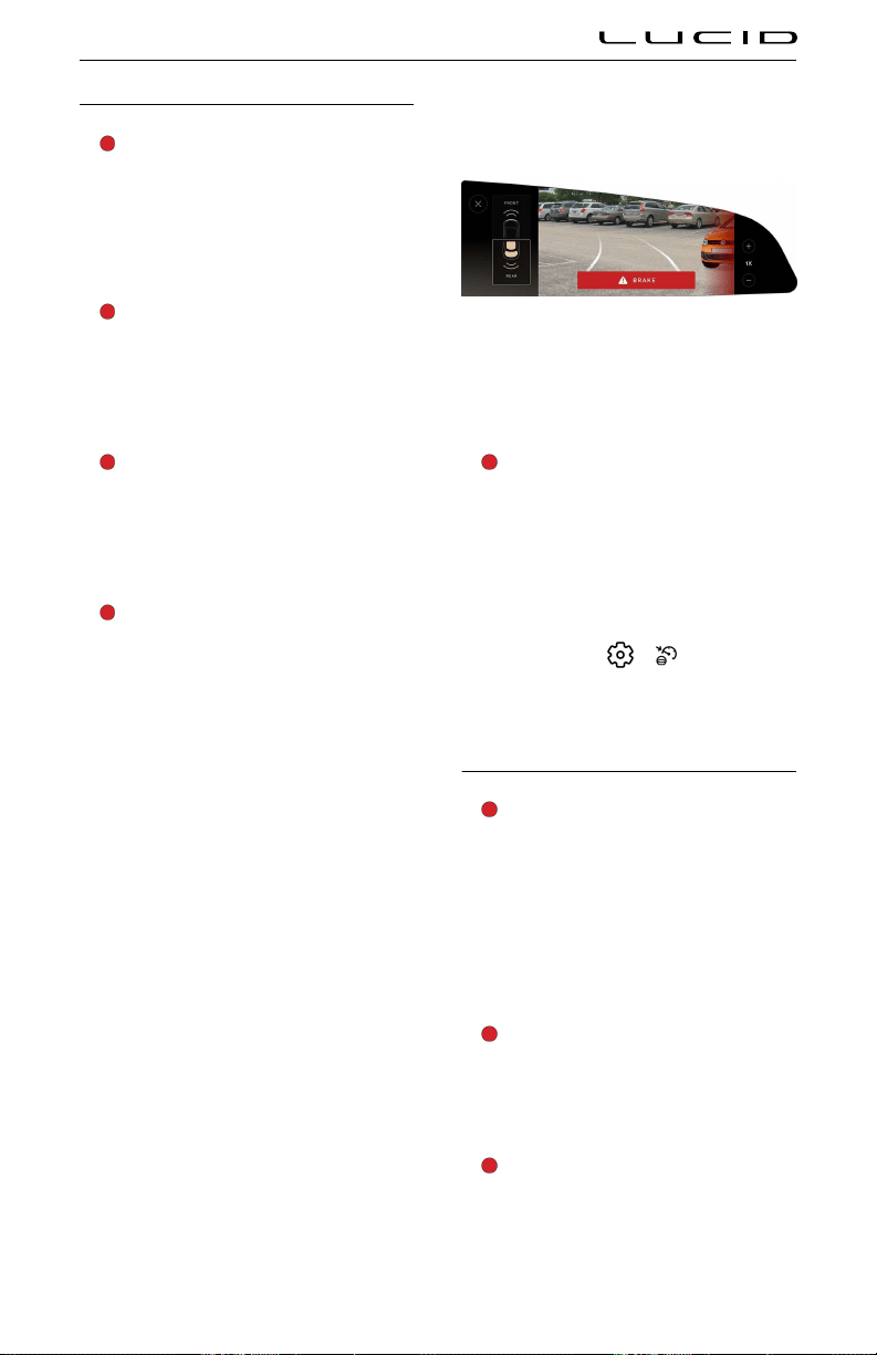
Cross Traffic Protection
WARNING: Cross Traffic Protection
is an assist feature only, and is
not a substitute for attentive driving
and sound judgment. The driver is
responsible for paying attention while
driving, monitoring the surroundings,
and braking or steering the vehicle
when necessary.
WARNING: There are factors that can
reduce or impair the performance of
the Cross Traffic Protection system,
causing either unnecessary, invalid,
inaccurate, or missed warnings. Do not
rely solely on Cross Traffic Protection to
warn you of a potential collision.
WARNING: Cross Traffic Protection
does not detect smaller objects outside
of the range of the sensors. This
could include (but is not limited to)
small children or animals. Be aware of
your surroundings at all times while
operating the vehicle.
WARNING: Cross Traffic Protection
does not provide alerts when the driver
is already applying the brake.
Cross Traffic Protection warns the driver when
there is a risk of collision with crossing traffic
approaching from the left or right to the front
or rear side of the vehicle and will automatically
apply emergency braking if needed.
When enabled, Cross Traffic Protection is
active at speeds below 10 mph (16 km/h) for
warnings, and speeds below 6 mph (10 km/h)
for braking.
Note: Cross Traffic Protection is not available
when the gear is in P (Park). Front cross traffic
alerts or braking will not be issued if vehicle
speed exceeds 10 km/h or driven distance
is over 40m after shifting from P (Park) to
D (Drive) gear.
When the gear is in D (Drive) or N (Neutral)
and forward vehicle motion is detected, Cross
Traffic Protection will sound an alert and
prompt on the Instrument Cluster when a
collision risk is detected.
If the vehicle is moving and the driver does
not react in time, the system will activate
emergency braking.
When the gear is in
R (Reverse) or N (Neutral)
and backward vehicle motion is detected, Cross
Traffic Protection will sound an alert and
prompt on the right Cockpit Panel when a
collision risk is detected.
If the vehicle is moving and the driver does
not react in time, the system will activate
emergency braking.
Cross Traffic Protection settings
WARNING: Lucid strongly recommends
that you do not disable Cross Traffic
Protection when driving. Disabling
this feature deactivates alerts and
emergency braking which increases the
risk of causing or contributing to a
crash.
To configure Cross Traffic Protection, from
the Pilot Panel touch
> DreamDrive,
then press to enable or disable Cross Traffic
Protection. Settings save to the current User
Profile.
Lane Departure Protection
WARNING: Lane Departure Protection
is for guidance purposes only and is
not intended to replace your own direct
visual checks. Never depend on Lane
Departure Protection to inform you of
unintentionally driving outside of the
boundaries of the driving lane or road
edge. Always stay alert, pay attention to
the driving lane and always be aware of
other road users. Failure to do so can
result in serious injury or death.
WARNING: Lane Departure Protection
is designed to detect lane markings
and certain road edges. It is your
responsibility to drive attentively and
stay within the boundaries of the
driving lane.
WARNING: Any changes to the vehicle's
suspension or wheel height may result
in degraded feature performance or no
activation.
Advanced Driver Assistance Systems (ADAS) 108

WARNING: Excessive crosswinds, large
road crown, improper tire pressures, or
vehicle loading conditions can affect
the feature's performance.
When enabled, Lane Departure Protection
helps the driver to prevent the vehicle from
unintentionally straying out of a detected
lane by providing visual and haptic alerts (if
enabled).
Lane Departure Protection is available
at vehicle speeds between 30‑124 mph
(50‑200 km/h) for detecting lanes, and between
40‑85 mph (60‑140 km/h) for detecting road
edges.
Note: Lane Departure Protection is temporarily
overridden when a turn signal is activated
(see Turn Signals). Once you have steered into
another lane and the turn signal automatically
deactivates, Lane Departure Protection will
resume if lane lines are detected.
When the system detects an unintentional drift
toward the lane or road boundaries:
- An alert will display on the Instrument
Cluster, highlighting the side the vehicle
is drifting towards.
- If enabled, the steering wheel will provide
a haptic vibration.
- Steering correction is applied to bring the
vehicle back into the lane or road.
If two or more steering corrections are detected
within 180 seconds without the driver’s hands
on the steering wheel, an audible alert will
sound on the second correction. For any
consecutive steering corrections, audible alerts
will be longer in duration.
Lane Departure Protection alerts will be
canceled immediately if any of the following
actions happen:
- A turn signal is activated
- Intentional steering
- Intentional acceleration
- Intentional braking
Lane Departure Protection settings
To configure Lane Departure Protection, from
the Pilot Panel touch > DreamDrive,
then enable or disable Lane Departure
Protection. Settings save to the current User
Profile.
When Lane Departure Protection is
disabled or unavailable, an indicator
will display on the Instrument Cluster.
When enabled, press INTERVENTION ONLY
(default) or WARNING AND INTERVENTION if
you wish to receive haptic vibrations of the
steering wheel when a steering correction is
recommended.
Warnings cancel automatically when the risk
of an unintentional lane departure has been
reduced (such as when you steer the vehicle
back to the current lane).
Note: When disabled, Lane Departure
Protection settings will save to the current
User Profile. Lane Departure Protection is re-
activated when Highway Assist is activated.
See Highway Assist. When Highway Assist is
activated, it is always set to 'Warning and
Intervention'.
Blind Spot Warning
WARNING: Blind Spot Warning should
not be used as a replacement for
checking the interior and exterior
mirrors or looking over your shoulder
before changing lanes. It's the driver's
obligation to stay alert, pay attention to
traffic, and take action if necessary.
WARNING: Blind Spot Warning may
not cover an extended blind spot zone
when a trailer is attached to a detected
vehicle.
Advanced Driver Assistance Systems (ADAS) 109
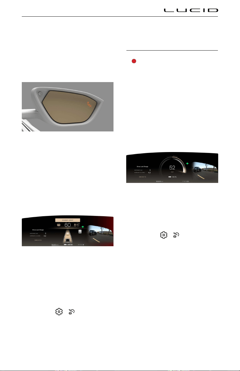
Blind Spot Warning provides visual and (when
enabled) audible warnings when the vehicle is
in motion and the system detects an object
in your blind spot or close to the side of your
vehicle.
Warnings cancel automatically when the risk
of a collision is no longer present, or when a
vehicle is no longer detected in the blind spot.
When an object is detected in a blind spot,
the amber LED in the mirror on that side will
illuminate.
Note: If the vehicle speed is above 6 mph
(10 km/h) and a turn signal is activated in the
direction of the object, the amber LED in the
corresponding mirror will flash.
If a turn signal is activated in the direction of
the object in a blind spot, visual and (when
enabled) audible warnings will activate.
If Blind Spot Display is activated, a camera view
of that blind spot will also be displayed. See
Blind Spot Display.
Note: Blind Spot Display is only available at
vehicle speeds above 25 mph (40 km/h).
Blind spot warning settings
To configure Blind Spot Warning, from the
Pilot Panel touch > DreamDrive, then
press to enable or disable Blind Spot Warning.
Settings save to the current User Profile.
When enabled, press to select whether to
receive VISUAL (default) or VISUAL AND AUDIO
warnings. If disabled, visual and audible
warnings on the Instrument Cluster are no
longer issued. Warnings via LED's on exterior
rear view mirrors are still provided.
Blind Spot Display
WARNING: Blind Spot Display should
not be used as a replacement for
checking the interior and exterior
mirrors or looking over your shoulder
before changing lanes. It is the driver's
obligation to stay alert, pay attention to
traffic, and take action if necessary.
Blind Spot Display uses the exterior cameras
to project an image of the blind spot field of
view onto the Instrument Cluster when a turn
signal is activated, helping the driver to assess
the surroundings. See Turn Signals.
Note: Blind Spot Display is only available at
speeds above 25 mph (40 km/h).
With Blind Spot Display enabled, activating a
turn signal will bring the camera view up for
that side on the Instrument Cluster.
Blind Spot Display settings
To configure Blind Spot Display, from the
Pilot Panel touch
> DreamDrive, then
enable or disable Blind Spot Display on Glass
Cockpit. Settings save to the current User
Profile.
Advanced Driver Assistance Systems (ADAS) 110
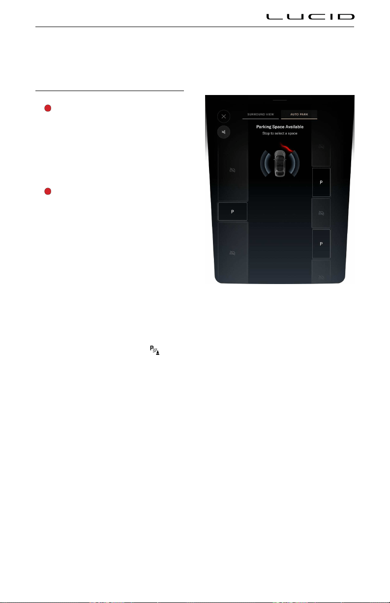
Parking Experience
Automatic Park In
WARNING: Automatic Park In does not
consider objects located outside the
range of sensors during the detection
of parking spaces or calculating the
parking path. Continually check your
surroundings throughout the parking
sequence. Be prepared to apply the
brake and take control to avoid
pedestrians, vehicles, or objects.
WARNING: It is the driver’s
responsibility to determine whether it
is safe and legal to park in a parking
space detected by Automatic Park In.
Automatic Park In takes control of shifting,
accelerating, braking, and steering the vehicle
into a parking space.
Note: The sensors only detect parking spaces
that are bounded by a three-dimensional object
on at least one side (such as an open space
next to a vehicle or between two vehicles).
Note: Automatic Park In cannot detect or park
in diagonal spaces.
Using Automatic Park In
To activate Automatic Park In, press
on
the Pilot Panel. Once activated, the system
searches for parking spaces using the exterior
sensors. Drive forward slowly to allow the
system to scan the surroundings.
Note: The vehicle must be moving below
approximately 15 mph (25 km/h) to scan. If it
is moving too fast, the system will prompt you
visually and audibly to slow down.
Note: You must drive past a space before it can
be fully detected.
Detected spaces will be displayed on the Pilot
Panel and instrument cluster. An audible alert
will sound for each one. If you wish to park in a
detected space:
1. Bring the vehicle to a full stop.
2. Press and hold the brake pedal.
3. On the Pilot Panel, press a space to select
it.
Note: The system can detect up to 4 parking
spaces at a time.
Advanced Driver Assistance Systems (ADAS) 111

When the system prompts you, release the
brake pedal and steering wheel to begin
parking. An audible alert will sound when
vehicle movement begins. During Automatic
Park In, the rear view camera displays on the
right Cockpit Panel.
The Pilot Panel will display parking in progress.
Monitor your surroundings throughout the
parking sequence and be prepared to take
control of the vehicle at any time.
- Automatic Park In can be stopped at any
time by pressing the brake pedal, and will
resume automatically when the brake is
released.
- If a system detects an obstacle in the
vehicle's trajectory, it will stop the vehicle
and prompt you to brake. When the
hazard has cleared, the RESUME button
on the Pilot Panel becomes available.
Press RESUME and release the brake to
continue the parking sequence.
WARNING: Automatic Park In does
not guarantee braking for an obstacle.
The driver is responsible to observe
surroundings and brake as needed.
- Press CANCEL at any time to stop
Automatic Park In. Be prepared to take
control of the vehicle. See Automatic Park
In on page 111.
Note: When the vehicle switches gears, an
audible alert will sound.
The Pilot Panel will prompt when parking has
completed and an audible alert will sound.
The vehicle will automaticallyshift into P when
parking has completed,
Note: If the system detects a curb or slope, it
will set the wheels accordingly. To disable this
feature, see Automatic Park In on page 111.
Canceling Automatic Park In
During the automated parking sequence,
Automatic Park In will be canceled immediately
if any of the following incidents occur:
- System or sensor faults
- Driver presses the accelerator pedal,
holds the steering wheel, or shifts gears
- Driver unbuckles the seat belt
- Driver presses
CANCEL on the Pilot Panel
- The trunk, the hood, or a door is not
closed
- The selected parking space is found to be
too small after initial scan
- System cannot park safely after 8 tries
Advanced Driver Assistance Systems (ADAS) 112

- Road slope or grade is too high
- Road is too slippery or provides poor tire
traction
- A safety system activates (such
as Collision Protection or Automatic
Emergency Braking. See
Collision
Protection on page 106)
When the system is canceled, the vehicle will
stop, emit an audible alert, and prompt the
driver to take control of the steering wheel
and brake pedal. If there is no response
from the driver after 30 seconds, the vehicle
automatically shifts into P (Park).
If Automatic Park In cancels for any of the
aforementioned reasons and you wish to use
the system again, you must start over at the
beginning of the process and scan for a space.
Automatic Park In settings
To configure Blind Spot Display, from the
Pilot Panel touch
> DreamDrive,
then press to enable or disable
Autopark Wheel Curb Assist. Settings save to
the current User Profile.
Automatic Park Out
WARNING: Automatic Park Out does
not consider objects located outside
the range of sensors during the pull-out
sequence, including oncoming traffic.
Continually check your surroundings
throughout the pull-out sequence, and
be prepared to apply the brake and take
control to avoid hazards.
Automatic Park Out takes control of shifting,
accelerating, braking, and steering the vehicle,
positioning it to pull straight out of a parallel
parking space.
Note: Automatic Park Out is only used to help
exit parallel parking spaces.
Note: Automatic Park Out can only be activated
when the vehcile is in P (Park).
Using Automatic Park Out
To activate Automatic Park Out, press
on
the Pilot Panel. Press and hold the brake pedal,
then tap the direction to pull out. Keep holding
the brake pedal while the vehicle scans the
available space.
When the system prompts you, release the
brake and steering wheel to begin the pull-
out sequence. An audible alert will sound
when vehicle movement begins. A turn signal
activates in the direction you're turning out.
Note: The driver is still responsible to make
sure the turn signal is in the correct direction.
During Automatic Park Out, the rear view
camera displays on the right Cockpit Panel.
Advanced Driver Assistance Systems (ADAS) 113

The Pilot Panel displays "unpark in progress".
Monitor your surroundings throughout the
sequence and be prepared to take control of
the vehicle at any time.
- Automatic Park Out can be stopped at
any time by pressing the brake pedal, and
will resume automatically when the brake
is released.
- If a system detects an obstacle in the
vehicle's trajectory, it will stop the vehicle
and prompt you to brake. When the
hazard has cleared, the RESUME button
on the Pilot Panel becomes available.
Press RESUME and release the brake to
continue the parking sequence.
- Press CANCEL at any time to stop
Automatic Park Out. Be prepared to take
control of the vehicle. See Automatic Park
Out on page 113.
Note: When the vehicle switches drive modes,
an alert sounds.
When the system has completed the sequence:
- The gear will automatically shift into
D (Drive).
- The system will hold the vehicle in place
with the brake.
- The Pilot Panel will prompt you visually
and audibly to take control of the vehicle.
If there is no response from the driver after
20 seconds, the gear will automatically shift
into P (Park).
Note: If Park Out direction is unavailable, the
pilot panel will alert you:
Canceling Automatic Park Out
During the automated pull-out sequence,
Automatic Park Out will be canceled
immediately if any of the following incidents
occur:
- System or sensor faults
- Driver presses the accelerator pedal,
holds the steering wheel, or shifts gears
- Driver presses
CANCEL on the Pilot Panel
- Driver unbuckles the seat belt
- The trunk, the hood, or a door is not
closed
- The selected parking space is found to be
too small after initial scan
- System cannot park safely after 8 tries
- Road slope or grade is too high
- Road is too slippery or provides poor tire
traction
- A safety system activates (such
as Collision Protection or Automatic
Emergency Braking. See Collision
Protection on page 106)
Advanced Driver Assistance Systems (ADAS) 114
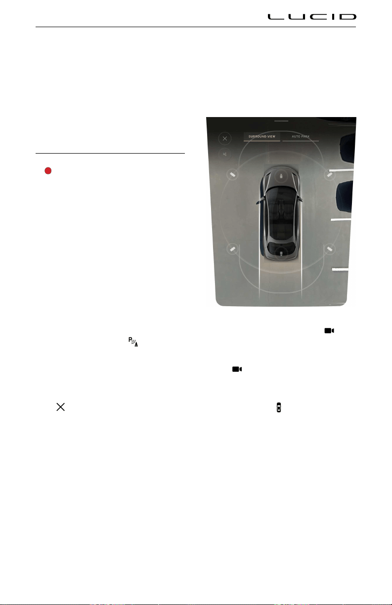
When the system is canceled, the vehicle will
stop, emit an audible alert, and prompt the
driver to take control of the steering wheel
and brake pedal. If there is no response from
the driver after 20 seconds, the gear will
automatically shift into P (Park).
If Automatic Park Out cancels for any of the
aforementioned reasons and you wish to use
the system again, you must start over at the
beginning of the process.
Surround View Monitoring
WARNING: The Surround View
Monitoring system should not be used
as a replacement for looking into the
interior and exterior mirrors or looking
over your shoulder when operating and
parking the vehicle. Always inspect your
surroundings with your own eyes.
The Surround View Monitoring system uses
the exterior cameras to display the immediate
vehicle surroundings in real time. This system
assists you in situations such as parking or at
exits with reduced visibility.
Note: Surround View Monitoring is only
available when the vehicle’s speed is below
9 mph (15 km/h).
Using Surround View Monitoring
To activate the system, press
on the Pilot
Panel, then select SURROUND VIEW.
When the gear is in R (Reverse), Surround View
Monitoring will activate automatically on the
Pilot Panel.
Press
at any time to close the screen.
Note: When Park Distance Warning is activated,
visual indicators for object distance will be
displayed. See Park Distance Warning.
To manipulate the view, use any of the following
screen gestures:
- Use one finger to press and drag, panning
the screen to move the camera angle in
any direction.
- Double-tap the screen to zoom and center
on the image. Double-tap again to zoom
out.
- Pinch inward with two fingers on the
screen to zoom out the camera angle.
Reverse the gesture to zoom in.
- Use all five fingers to pinch in on the
screen, and the system will return to the
default top-down view.
In the default top-down view, press a
camera button to switch to a 3D view from that
camera angle.
Press a
camera button on the front or rear
of the displayed vehicle to switch to the camera
view from the front or rear bumper.
In 3D view, press the
button to switch to
the top-down view.
Surround View Monitoring limitations
In addition to the limitations of Advanced
Driver Assistance components (see ADAS
Limitations), the Surrounding View Monitoring
system may not function correctly in these
situations:
- The trunk, the hood, or a door is not
closed
- The side mirrors are folded in
- The trunk or hood is open
Advanced Driver Assistance Systems (ADAS) 115
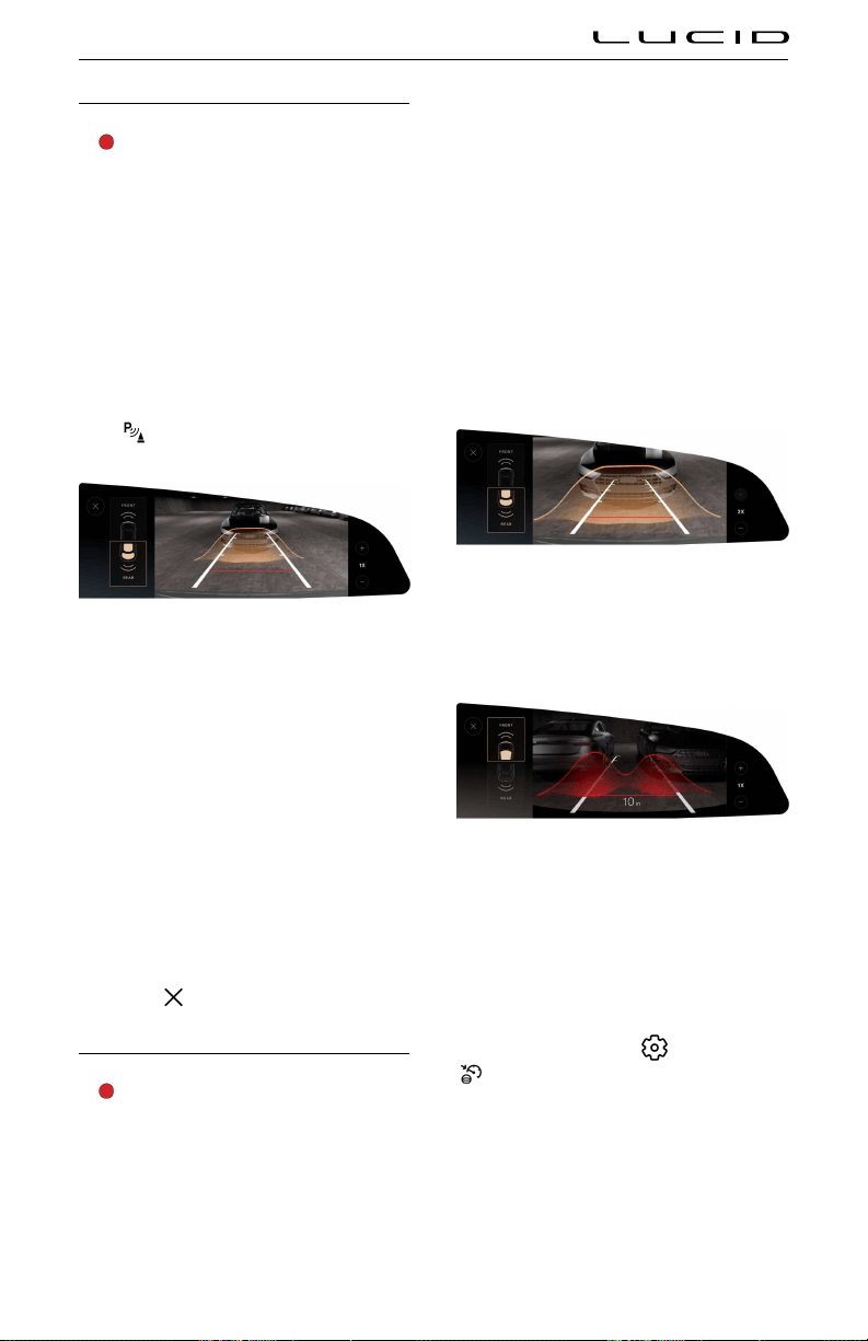
Rear View Monitoring
WARNING: The Rear View Monitoring
system should not be used as a
replacement for looking into the interior
and exterior mirrors or looking over
your shoulder when operating and
parking the vehicle. Always inspect your
surroundings with your own eyes.
Rear View Monitoring is an assist feature that
automatically displays the rear camera view on
the right Cockpit Panel when the vehicle shifts
into R (Reverse). See Selecting a Drive Mode.
To manually activate Rear View Monitoring,
press
on the Pilot Panel.
To manipulate the camera view, do any of the
following:
- Swipe down on the screen to switch to
the front camera view, or swipe up for the
rear camera view.
- Pinch outward with two fingers on the
screen to zoom in the camera angle.
Reverse the gesture to zoom out.
Note: The current magnification level will
be displayed to the right of the camera
view.
- Press the +/- buttons to zoom the view
in/out.
- Press
to close the screen.
Park Distance Warning
WARNING: Park Distance Warning is
an assist feature only, and will not
act to prevent a collision. It is the
driver’s responsibility to assess the
surroundings and take action when
necessary.
Park Distance Warning uses the exterior
sensors to provide you with visual and audible
alerts when the vehicle is slowly moving
towards a potential hazard.
Note: This feature is only available at speeds
below 10 mph (15 km/h).
When enabled, the system provides visual and
audible alerts on these camera views:
Right Cockpit Panel:
- Rear View Monitoring
Pilot Panel:
- Surround View Monitoring
The shade of the visual indicator represents
how close your vehicle is to an object. Objects
that are further away will be indicated by a
neutral shade.
As your vehicle approaches an object, the
visual indicator will gradually intensify to a
darker shade of red. If this happens, apply the
brakes to slow the vehicle and take any other
appropriate corrective action.
Park Distance Warning settings
To configure Park Distance Warning settings,
from the Pilot Panel touch
>
DreamDrive, then enable or disable Park
Distance Warning. Settings save to the current
User Profile.
Advanced Driver Assistance Systems (ADAS) 116
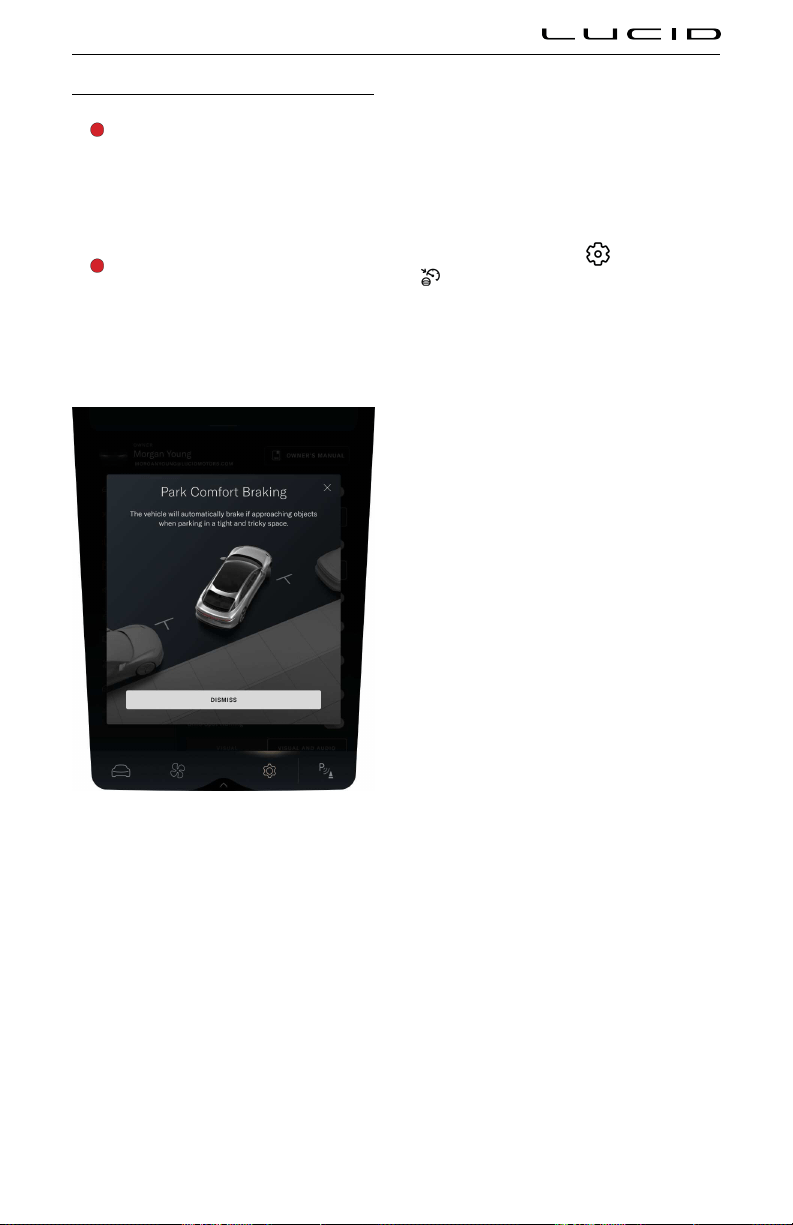
Park Comfort Braking
WARNING: Park Comfort Braking is
an assist feature only, and is not
a substitute for attentive driving
and sound judgment. The driver is
responsible for viewing and assessing
the surroundings, and braking or
steering the vehicle when necessary.
WARNING: There are factors that can
reduce or impair the performance of the
Park Comfort Braking system, causing
either unnecessary braking or failure
to brake. Do not rely solely on Park
Comfort Braking to stop the vehicle.
When Park Comfort Braking is enabled, the
system will automatically brake for you if it
detects objects in the vehicle’s path as you
close in on a parking space.
Park Comfort Braking can be overridden
by taking your foot off of the accelerator
pedal, then pressing again. This will deactivate
Comfort Braking for the next 6 feet (2 meters)
of driving distance.
Twenty seconds after a braking event, the
system will first hold the vehicle stationary for
driver to take over control, and then put the
vehicle in P (Park) unless the driver:
- Presses the brake pedal
- Drives away from the object
- Shifts to the opposite direction, from
R (Reverse) to D (Drive) or vice versa
Note: Park Comfort Braking is only available at
speeds below 5 mph (9 km/h).
Park Comfort Braking settings
To configure Park Comfort Braking settings,
from the Pilot Panel touch
>
DreamDrive, then enable or disable Park
Distance Warning. Settings save to the current
User Profile.
Advanced Driver Assistance Systems (ADAS) 117

User Proiles
About User Profiles
You can create multiple User Profiles for your
vehicle, enabling everyone to personalize their
vehicle settings, including:
- Preferences for entry to and exit from the
vehicle (see Loading and Switching Profile
Preferences on page 120)
- Seat positioning (see Adjusting Front
Seats)
- Positioning of exterior mirrors (see
Adjusting the Exterior Side Mirror Position
on page 74)
- Certain Drive settings (see Drive Modes
on page 73)
- Preferences for units of measurement
(press
> Displays > Units).
- Paired Bluetooth® phones, including
synced contacts, calls, and messages (see
Pairing a Bluetooth Device on page 131)
- Music and audio preferences, such as
radio stations and third-party media
applications (see Playing Media from
Devices on page 127)
- Interior lighting and display themes (see
Interior Lights on page 78)
- Personalized Home and Work navigation
destinations (see Maps and Navigation on
page 128)
User Profile types
There are three types of User Profiles, each
with its own levels of access:
- Owner: This is the main Profile with
access to all features, including Lucid ID
syncing and User Profile removal. There
is only one Owner Profile. See Creating a
User Profile on page 118.
- Secondary Driver: Additional regular users
of the vehicle who would like to create
a User Profile can store their individual
preferences and settings. The vehicle can
save up to three Secondary User Profiles.
See Creating a User Profile on page 118.
- Guest: This is for any user who requires
temporary access to the vehicle or any
regular user who does not wish to create
a Profile. The Guest Profile does not have
access to any profile detection features
and will not save adjustments to the seat,
steering wheel, or external mirrors. There
is only one Guest Profile.
Creating a User Profile
Setting up the Owner Profile
In a new vehicle, an Owner Profile setup prompt
will appear on the right Cockpit Panel at the
end of a driving session. Press SET UP to begin
the setup process.
To access setup manually on the Pilot Panel,
press
> Access and Profiles, then
press SET UP THIS PROFILE.
Note: The vehicle gear must be set to P (Park)
and remain there throughout the setup process.
Note: Do not skip the first step, but you
can press EXIT SETUP on any subsequent
steps and complete them later via the
Access and Profiles menu. You can also
press < to return to the previous step.
1. Sign in with your Lucid ID. This allows
your data to be synced to other Lucid
vehicles and to the Lucid mobile app,
through which you can remotely access
your vehicle and its data.
Note: Your Lucid ID is set up at the time
you purchase your vehicle. If you cannot
locate your login information, contact
Lucid Customer Care for assistance. See
Customer Care on page 210.
2. Enter a profile name and select an avatar.
Infotainment 118

3. Enter a 5-digit Personal Identification
Number (PIN) of your choosing, then enter
it again to confirm.
Confirm your identity with your pin if you
choose not to enable Face Login. See
Face Unlock on page 120.
4. Press to link a key fob or phone to your
Profile. Your vehicle will automatically
load your Profile if your linked device is
detected.
Follow the on-screen directions to link a
device.
Note: The device must be in your hand
during setup, as some user interaction is
required. If linking a smartphone, have
the Lucid mobile app opened and sign
into it with your Lucid ID.
5. Use the touchscreen to set your Home
and Work addresses. This allows you to
access shortcuts to these destinations,
such as when using maps. See Maps and
Navigation on page 128.
6. Set up facial recognition to quickly load
your profile when you enter the vehicle.
Setting up Additional Profiles
To add another User Profile:
- Sign in using the Owner Profile.
- Make sure the vehicle is parked, and
remain there throughout the setup
process.
On the right Cockpit Panel, press + Profile
Settings to launch the Access & Profiles
Settings on the Pilot Panel.
On the Pilot Panel, press
>
Access and Profiles, then press
CREATE NEW PROFILE.
Note: The option to create or add a User Profile
will not be available if the maximum number
of Profiles has already been added. If you wish
to delete a Profile in order to add another, see
Removing Secondary User Profiles on page 120.
1. Enter a profile name, and select an avatar.
2. Press to link a key fob or phone to the
Profile. Your vehicle will automatically
load the Profile if the linked device is
detected.
Follow the on-screen directions to link a
device.
Note: The device must be in your hand
during setup, as some user interaction is
required. If linking a smart phone, you
must have the Lucid mobile app opened
and be signed into it with your Lucid ID.
Profile Settings
There are multiple ways to access your User
Profile settings:
- On the right Cockpit Panel, press
your avatar image, then select
PROFILE SETTINGS to launch.
- On the Pilot Panel, press
> Access and Profiles. From
here, you can press to tole
Automatically Load Preferences on or off
(see Loading User Profile Preferences), or
select from the listed menu options.
Changing profile name and avatar
In the Lucid Mobile App, you can change the
avatar for the Owner Profile and/or the name
and avatar for the Secondary Profiles .
My Profile
Under My Profile, you can view and edit
your Home and Work addresses or reset your
Personal Identification Number (PIN).
Note: Secondary Profiles must have access
granted from the Owner in order to reset a PIN.
When prompted, press REQUEST ACCESS. The
Lucid mobile app tied to the Owner’s Lucid ID
will need to be opened within a certain time
frame in order to grant access.
Profile Detection
Under
Profile Detection, you have the options
to add, edit, or turn detection methods on and
off.
Infotainment 119

Note: An active Guest Profile will not have
access to these settings.
Keys:
- Press to tole Key Detection on or off for
the active User Profile. See Loading User
Profile Preferences.
- CONNECTED KEYS lists any devices
currently linked to the active User
Profile. From here, you can edit or
remove existing devices, or add new
ones by pressing LINK KEY FOB or
LINK PHONE KEY.
Note: When adding a new phone or key
fob, make sure the device is in your hand
and follow the on-screen instructions.
Detect via Face Unlock:
- Press to tole Face unlock on or off for
the active User Profile. See Face Unlock.
- This menu will state whether the active
Profile has an appearance recorded
to it. Press to ADD APPEARANCE or
REMOVE APPEARANCE.
Face Unlock
Face Unlock allows you to load your User
Profile quickly when you enter your vehicle. The
interior camera behind the steering wheel uses
facial recognition to identify the seated driver
and loads any matching User Profile.
See Profile Detection to set up, enable, or
disable this feature.
Loading and Switching Profile Preferences
When you enter the vehicle and confirm
your User Profile, you will be prompted on
the right Cockpit Panel to CONFIRM loading
your preferences. This includes automatically
adjusting to the saved steering wheel, seat, and
mirror positions.
You can set your User Profile to automatically
load your preferences upon entry. See Profile
Settings.
Switching Between User Profiles
On the right Cockpit Panel, press the current
avatar image, then select any User Profile from
the list. Switching between User Profiles is only
available when the vehicle is in
P (Park).
Removing Secondary User Profiles
If desired, the Owner can delete existing
Secondary User Profiles from the vehicle.
Deleting a Profile will remove all data and
preferences for that User.
Note: Only the Owner can manage User
Profiles.
1. On the Pilot Panel, press
> Access and Profiles >
Remove Profiles.
2. Press EDIT to bring up the editing screen.
Infotainment 120

3. Press DELETE next to the profile to be
removed. You will be prompted to confirm
your selection.
Changing Display Settings
You can change the Unit of measure, Language,
and Timezone displayed. To change the display
settings:
On the Pilot Panel, select
> Displays, and
then tap either Units, Timezone, or System
Language.
Infotainment 121

Media and Audio
Media Overview
To launch media, tap the Media icon on the
Right Cockpit Panel.
Applications displayed in the Smart Drawer
window on the Right Cockpit Panel allow you
to browse the contents. The Pilot Panel view of
the smart drawer shows additional controls for
lists and libraries.
Tap on a media item to select and play media
from that source.
Infotainment 122
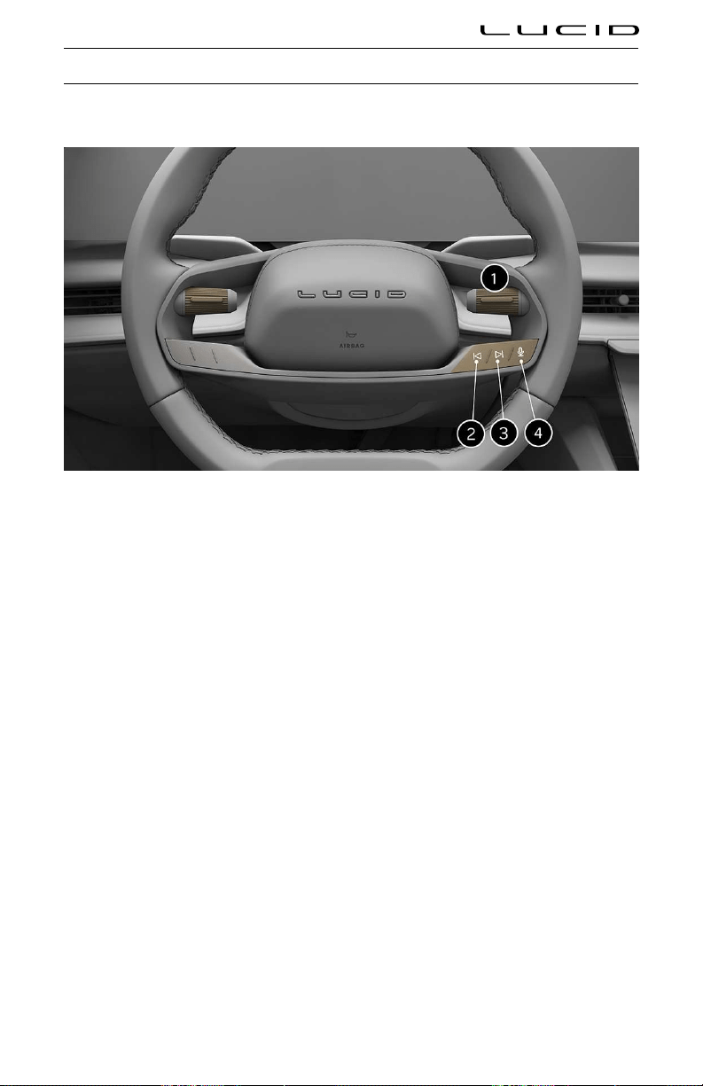
Physical Media Controls
Steering wheel media controls
When active media is playing, or a call is in progress, use the steering wheel controls as followed:
1. Right tole: Tole to control call/media volume. Press the button to play/pause the media
playback or to mute/unmute the radio.
2. Previous: Press to skip to the previous available media. When using the radio, press to scan to
the previous available frequency. See AM and FM Radio on page 125.
3. Next: Press to skip to the next available media. When using the radio, press to scan to the next
available frequency. See AM and FM Radio on page 125.
4. Voice Assistant: A short press invokes Alexa and long press invokes Siri or Google Assistant if
CarPlay or Android Auto are connected.
Infotainment 123

Dashboard Volume Control
When media is playing, the tole on the dashboard can be used adjust the volume. Scroll up to
increase or down to decrease.
Infotainment 124
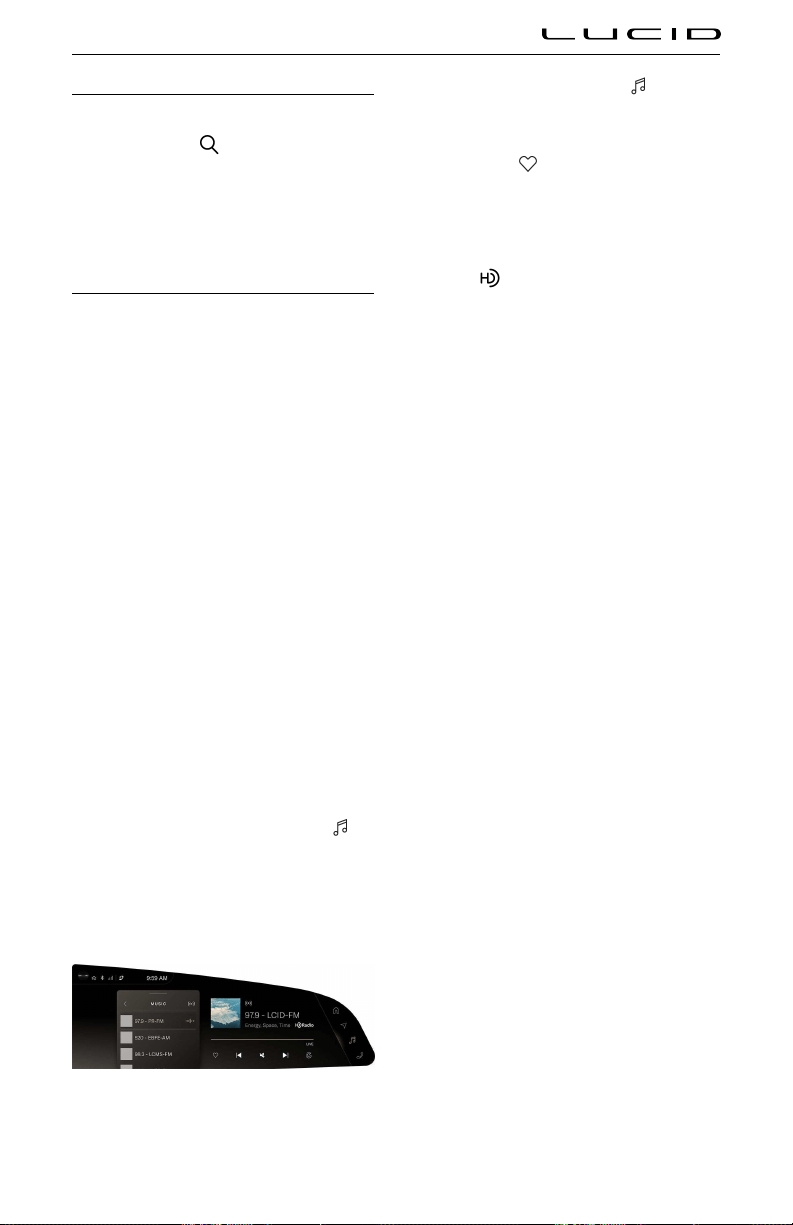
Searching Media Content
When media applications are opened on the
Pilot Panel, use the
search bar to search
for a particular song, album, artist, station, or
podcast. Note that search may not be avaiable
for a particular media source.
Note: Search functions are not available when
the vehicle is not in P (Park).
AM and FM Radio
About HD Radio™ Radio
Your vehicle is equipped with a special radio
receiver that can receive digital broadcasts of
local AM/FM stations in addition to analog
broadcasts. Many stations broadcast a digital
signal that may contain additional features not
found in an analog signal. For more information,
visit www.HDRadio.com.
HD Radio Technology manufactured under
license from iBiquity Digital Corporation. U.S.
and Foreign Patents. For patents see http://
dts.com/patents. HD Radio and the HD,
HD Radio, and “ARC” logos are registered
trademarks or trademarks of iBiquity Digital
Corporation in the United States and/or other
countries.
Lucid and iBiquity Digital Corp are not
responsible for the content sent using HD
Radio™ technology. Content may be changed,
added or deleted at any time at the station
owner's discretion.
Using the AM/FM Radio application
Launch the AM/FM Radio application from the
Right Cockpit Panel. Tap the Media icon
>
AM/FM Radio from the launcher menu, then
select AM/FM from the Smart Drawer.
From the main menu, you can select the
desired category of radio stations.
On the right Cockpit Panel, press > AM/FM
Radio. Selected media will display, along with
player controls.
- Press the
favorites icon to add the
current station to your Favorites list. The
icon is solid when a station has been
added to Favorites.
- When listening to an HD Radio station,
the
icon is highlighted. Tap a channel
number to switch stations.
HD Radio stations have a multicast indicator
(1 2 3….). These numbers will appear if the
current station has multiple digital broadcasts.
Press Seek Up or Down button repeatedly
to access the other digital broadcasts or
tap a channel number to switch stations.
The numbers that are highlighted signify
available digital channels where new/different
content is available. HD1 will signify the main
programming service and is available in analog
and digital broadcasts. Any additional multicast
stations (HD2–HD8) are only broadcast
digitally.
HD Radio Reception Factors
Reception Area: If you are listening to a
multicast (HD2, HD3..) station and you are on
the fringe of the reception area, the station
may mute due to weak signal strength. If you
are listening to HD1, the system will simply
switch to the analog broadcast until the digital
broadcast is available again.
However, if you are listening to any of the
possible multicast (HD2–HD8) channels, the
station will mute and stay muted unless it is
able to connect to the digital signal again.
While in this state, the “swirl” icon will appear
for a few seconds. If it is not able reconnect
to the digital signal, then the screen will
be cleared and text ‘station unavailable’ will
appear in artist and title field area
Station Blending: When a HD1 station is
received, the system will play the analog audio
broadcast from the station for a few seconds
and then, if the receiver verifies the station
is an HD Radio station, it will transition to
play the digital audio broadcast. Depending
on the station quality, you may hear a slight
sound change when the station transitions from
analog to the digital broadcast. The shift from
analog to digital or digital back to analog sound
is known as 'blending'.
Infotainment 125

Station Issues: In order to provide the best
possible experience, a contact form has been
developed to report any station issues found
while listening to a station broadcasting
with HD Radio technology. Every station is
independently owned and operated. These
stations are responsible for ensuring all audio
streams and data fields are accurate. This form
can be found at: https://hdradio.com/stations/
feedback/
Troubleshooting HD Radio
The table below describes how to troubleshoot
certain issues.
Experience Cause Action
Mismatch of
time alignment
a user may
hear a short
period of
programming
replayed or an
echo, stutter or
skip.
The radio
stations analog
and digital
volume is not
properly
aligned or the
station is in
ballgame
mode.
None, radio
broadcast
issue. A user
can contact the
radio station.
Sound fades,
blending in and
out.
Radio is
shifting
between
analog and
digital audio.
Reception
issue, may
clear up as the
vehicle
continues to be
driven.
Turning the
indicator of the
"HD Radio"
button o can
force radio in
an analog
radio.
Audio mute
condition when
an HD2/HD3
multicast
channel has
been playing.
The readio
does not have
access to digital
signals at the
moment.
This is normal
behavior, wait
until the digital
signal returns.
If out of the
coverage area,
seek a new
station.
Audio mute
delay when
selecting an
HD2/HD3
multi-cast
channel preset.
The digital
multicast
content is not
available until
HD Radio
broadcast can
be decoded
and make the
audio available.
This takes up
to seven
seconds.
This is normal
behavior, wait
for the audio to
become
available.
Experience Cause Action
Text
information
does not match
he present
song audio.
Data service
issue by the
radio
broadcaster.
Broadcaster
should be
notiied.
Complete the
form: https://
hdradio.com/
stations/
feedback.
No text
information
shown for the
preset selected
frequency.
Data service
issue by the
radio
broadcaster.
Broadcaster
should be
notiied.
Complete the
form: https://
hdradio.com/
stations/
feedback.
Loing into Media Applications
Many third-party media applications can be
loed into via the Pilot Panel, allowing you to
directly control and personalize your apps.
On the Pilot Panel, select
>
Applications for a list of available third-
party media.
Note: Many third-party media applications
require a data connection and login
information, and some services are
subscription-based. Refer to the provider for
more information.
Using Alexa Built-In
The Lucid Air comes equipped with Amazon
Alexa Built-In allowing users to give voice
commmands for navigating to destinations,
making phone calls, sending and receiving text
messages, playing music, adjusting temperature
and controlling smart home devices.
To sign in to Alexa:
1. From the Pilot Panel, go to Settings >
Applications > Alexa.
2. On your mobile device, go to
amazon.com/code and enter in the 5-
character code or scan the QR code
displayed on the Pilot Panel.
3. If you've connected a mobile device, you
will be prompted to enable Alexa to
access contacts and read messages.
Infotainment 126
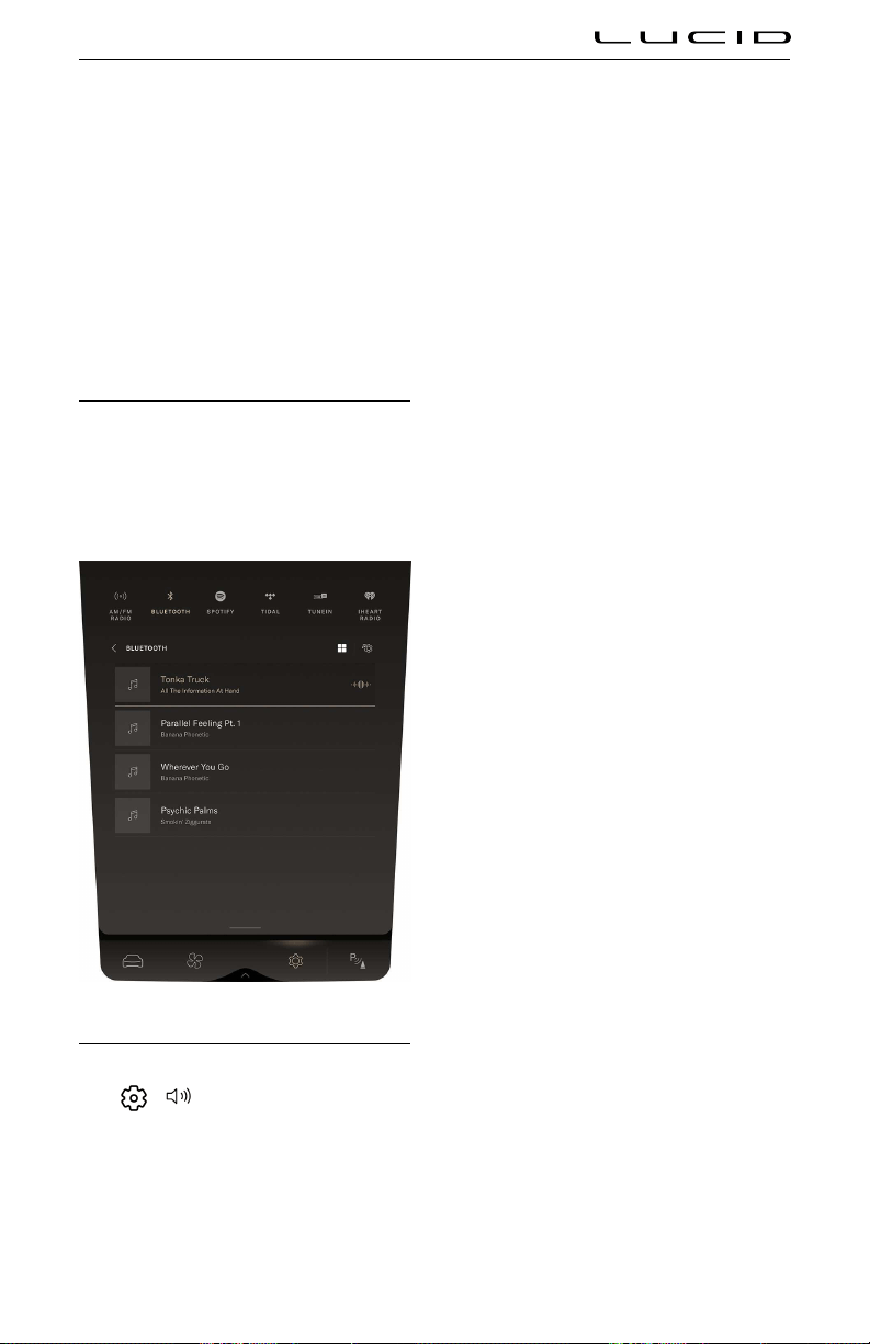
4. If you've not previously connected a
mobile device, you will be shown see the
Alexa Settings screen.
Once signed in, you can go to Settings >
Applications > Alexa > Things to Try to see a
list of sample Alexa commands.
You can invoke Alexa in one of two ways:
- Pressing the voice button on the steering
wheel.
- Saying "Alexa."
Playing Media from Devices
The infotainment system can play media from
Bluetooth® connected devices (see Pairing a
Bluetooth Device on page 131). From the list of
media applications on the right Cockpit or Pilot
Panel, select Bluetooth® source.
Audio Settings
To access the audio settings on the Pilot Panel,
select
> Audio.
- Equalizer: Adjusts the bass, mid, and
treble
- Balance: Adjusts the sound level between
the speakers
- Volume: Adjusts the master volume,
as well as the volume levels for the
navigation system and phone
Infotainment 127

Maps and Navigation
Navigation Overview
To access navigation, press the icon on
the right Cockpit Panel. This screen will display
your current location and street name (where
applicable).
If you pan away from the current location, the
street name will be replaced by a Recenter
button. Pressing Recenter is a quick way to
return to the default view showing the current
position.
Note: Upon first use of the navigation system by
a User Profile, that user will receive a prompt
and must read and agree to the Terms and
Conditions before proceeding.
The smart drawer can expand the Navigation
screen into the Pilot Panel for additional details
menus not available in the smaller Cockpit
Panel.
Navigating
To navigate to a location, open the smart
drawer on the right Cockpit Panel to select a
destination. Alexa voice commands can also
be used to quickly navigate hands-free to a
location.
Note: Swipe left or right to view additional
destination categories. The Recent Destinations
will populate as you make routes to different
destinations. Save locations using the "heart"
icon after searching for a location.
Move the smart drawer into the Cockpit Panel
to access additional options:
-
RECENT DESTINATIONS: Select from a
list of recently-used destinations.
- HOME and WORK: Select from your saved
home and work locations. See Setting
Home and Work Destinations
on page
129.
- Use the Search bar to type in an address
via the on-screen keyboard.
Note: Keyboard search functions are only
available when the vehicle is not moving.
All other Search functions are available at
all times.
Once a location is specified, the map will zoom
out to display an overview of the proposed
route on the MY ROUTE screen, including
the estimated time of arrival (ETA) and total
distance.
Note: Because theAuto‑add Charging feature
is enabled, the system will calculate the
battery power needed for the trip and the
recommended charging time for each charging
stop.
The DETAILS tab lists details on each stop in
your trip.
When a trip is started, the smart drawer
minimizes to make room for turn-by-turn
guidance at the top of the Cockpit Panel.
Navigation instructions will remain in view while
a Route is in progress.
Infotainment 128

Press END or use voice commands ("Alexa,
cancel navigation") to end navigation.
Charging Locations
From the main Navigation smart drawer, the
CHARGING category can be selected to view
nearby charging stations.
Adjusting the Map
The Pilot Panel map can be rotated, panned,
or zoomed in and out via the touchscreen.
Any time the map is manipulated beyond
your vehicle’s current position, the RE-CENTER
button will appear; tap it to return to your
current position.
To zoom in the map, use one finger to double-
tap the touchscreen. To zoom out the map, use
two fingers to tap the touchscreen. To see a
3D view of the map, swipe two fingers on the
touchscreen.
The map centers around your current location
by default, and the current street name is
displayed. If not using navigation, Passive
Lane Guidance may also appear above the
current street name, indicating the number and
direction of lanes for the current road.
The Pilot Panel defaults to the same view as
the Cockpit Panel, but it can maintain its own
independent map setting and zoom level. Touch
the icon in the lower right of the map to change
views:
- Range Map: Shows the approximate range
that can be traveled using your current
level of charge
- 3D Track-Up: 3D view that tracks your
vehicle’s current position
- 2D Track-Up: 2D view that tracks your
vehicle’s current position
- North-Up: 2D view where North is always
at the top of the map
- Route Overview: Displays your current
route
Note: The
Route Overview option only appears
when a route is selected.
Predicting Energy Usage
The Auto‑add Charging feature is always on
and will help anticipate the vehicle’s charging
needs for a trip. This feature automatically
adds charging stations to a calculated route as
needed.
Using Range On Map
The Lucid Range On Map provides a visual
representation of anticipated range for the
given battery state of charge, traffic conditions,
elevation chages, and more. To display the
Range On Map, select the feature using the
map controls.
Figure 1:
Setting Home and Work Destinations
Common destinations such as your home or
workplace can be designated accordingly in the
system, allowing you quick access within the
Navigation menus.
When destination details are displayed in
the smart drawer, press an option to
Set as Home or Set as Work. Home
and Work locations can also be set using voice
commands and in Vehicle Settings.
The applicable icon will appear next to the
destination under its details.
Once a destination is set in this manner, the
option under its details will change to
Remove.
Infotainment 129

Map Updates and Offline Mode
When a data connection is present, the "self-
healing maps" are updated automatically over
the air with no user intervention as they
become available.
When your vehicle does not have an available
wireless internet connection, the navigation
system will pull from any existing map data
that was automatically downloaded and stored
by the vehicle based on driving and search
history. Any resulting information displayed will
be labeled as OFFLINE RESULTS, and will not
include live traffic conditions, EV-style routing,
charge plug availability.
Infotainment 130

Phone and Smart Devices
Bluetooth® Wireless Technology
When in operating range, you can pair a
Bluetooth-capable phone with your vehicle for
hands-free use. Bluetooth usually supports a
wireless connection of approximately 30 feet
(9 m), although range can vary based on
atmospheric conditions and the device used.
To use your phone with the vehicle, you must
pair it first. See Pairing a Bluetooth® Device.
Two devices can be connected simultaneously.
For example, If you own a personal phone
and wish to stream music while taking calls
from your work phone, you can connect a first
device for phone features, and second device
for media, or the same device can be connected
for both phone and media. Only one device can
be connected for each feature.
Note: Other Bluetooth -capable devices can
also be paired to your vehicle for use, such as
an iPad or Android tablet.
Pairing a Bluetooth Device
Pairing a phone to your vehicle enables you
to place and receive hands-free calls, and to
access your phone’s contacts, messages, and
recent call list. It also allows you to play media
from various media apps from your device.
Once a phone is paired to the vehicle, it will
automatically connect whenever it is in range.
To pair a device, have it with you in the vehicle
and ensure it has Bluetooth® enabled and
discoverable, then follow these steps:
1. On the Pilot Panel, select
>
Connectivity > Bluetooth®.
2. When Bluetooth is enabled from the
vehicle, this screen will scan for Bluetooth
enabled devices within range. Under
OTHER DEVICES, tap the device to be
paired. Pairing must be initiated from the
vehicle, and can not be done from your
device.
3. When prompted, press
CONFIRM if the
pairing code on the screen matches the
one on your device.
4. If prompted by your device, select
whether to allow access to your contacts
and messages.
5. After pairing is complete, you can change
device settings to enable phone, media, or
both.
When paired successfully, the name
of the device will be listed under
CONNECTED DEVICES.
Syncing Contacts and Messages
Once a phone is paired, you can configure
access to phone contacts and messages,
allowing you to make calls and display
messages from contacts stored in your phone.
Follow these steps:
1. On the Pilot Panel Bluetooth® screen,
press the three dots by a connected
device.
2. From this screen, you can tole the
options to sync messages and contacts.
Please note that larger contacts lists
can take more time to sync with the
vehicle. To sync your messages, go to
your mobile device's Bluetooth settings
and make sure you have allowed text
message notifications. Press SAVE to
keep these settings and return to the
previous screen.
Connecting and Disconnecting Bluetooth Enabled Devices
When a paired phone enters or exits the range
of your vehicle, it will connect or disconnect
automatically. If you wish to connect to a
different paired device:
1. On the Pilot Panel Bluetooth screen,
press Disconnect.
2. Press the DISCONNECT button next to
the device to be disconnected.
3. Press
DONEwhen you have finished
disconnecting any unwanted devices.
4. Under MY DEVICES, tap the name of the
device to be connected.
Infotainment 131
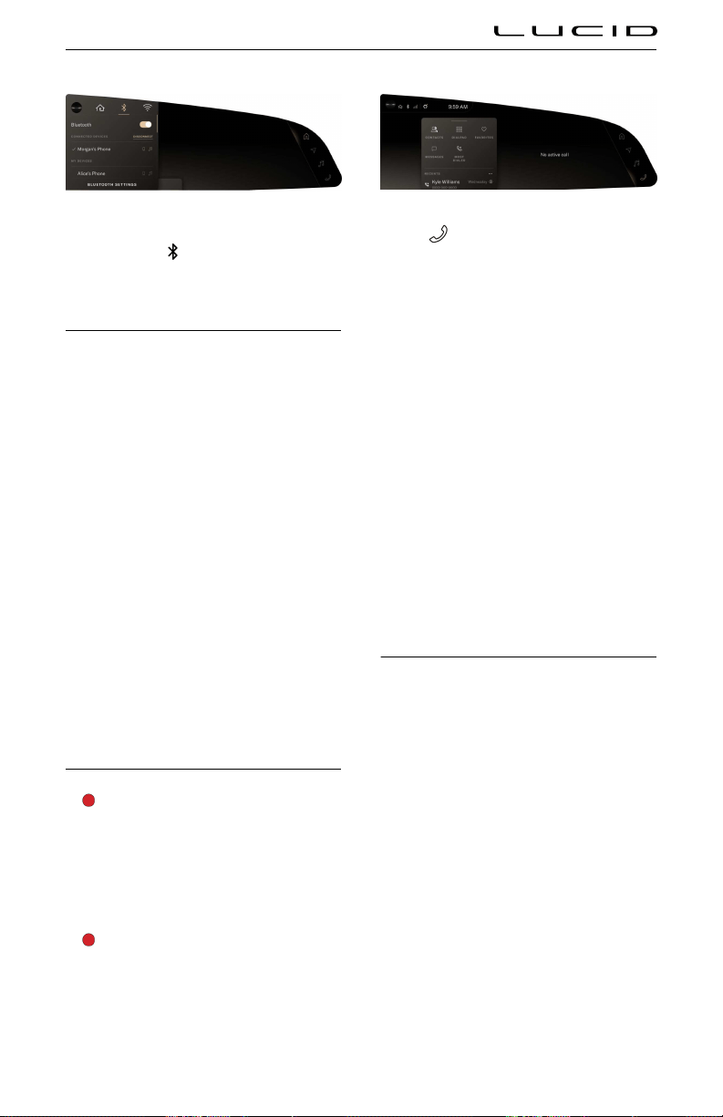
Alternately, you can use the right Cockpit
Panel. Press the
icon in the status bar
to display connected devices and connect or
disconnect.
Editing Bluetooth Enabled Device Preferences
To edit device preferences:
1. On the Pilot Panel Bluetooth screen,
press the three dots by a connected
device.
2. From this screen, select to allow your
vehicle to access the phone, audio,
or both features. Press SAVE to keep
these settings and return to the previous
screen.
If you no longer wish to use a device with the
vehicle:
1. On the Pilot Panel Bluetooth screen,
press Forget.
2. Press the FORGET button next to any
device you wish to remove, then press
FORGET at the prompt to confirm.
3. Press Done when you have finished
unpairing any unwanted devices.
Using the Phone App
WARNING: Distracted driving can lead
to loss of vehicle control and a collision,
which can result in serious injury or
death. Lucid strongly recommends that
the driver stay focused on the road at
all times while driving. Safe operation
of the vehicle is the driver’s primary
responsibility.
WARNING: Always ensure you are
following all applicable local laws
regarding the use of phones while
driving. This includes, but is not limited
to, laws that prohibit texting and require
hands-free phone operation at all times.
Tap the phone icon on the right Cockpit
Panel to open the Phone smart drawer.
When needed, the Phone smart drawer can
be opened on the Pilot Panel to show more
detailed lists and information.
- CONTACTS: Displays a synced contact
list. See Syncing Contacts and Messages.
Contacts can be searched and sorted on
the Pilot Panel.
- DIALPAD: Opens the dialpad for making
manual calls.
- FAVORITES: Displays a synced list of
favorite contacts.
- MESSAGES: Allows you to have text
messages read aloud and send preset text
messages. See Using Messages.
- MOST DIALED: Displays a list of
frequently dialed numbers.
Making and Receiving Phone Calls
To make a phone call, do any of the following:
- Select a contact from the CONTACTS,
FAVORITES, MOST DIALED, or RECENT
CALLS lists.
- Use the DIALPAD screen to manually dial
a number.
Note: If it is safe and legal to do so, you may
also make a call using the phone you have
paired to your vehicle.
Receiving a Call
Incoming calls from a paired phone will display
an alert on the right Pilot Panel. If your phone
contacts have been synced to the vehicle,
any contact information for that caller will be
displayed. See
Syncing Contacts and Messages
on page 131.
Infotainment 132
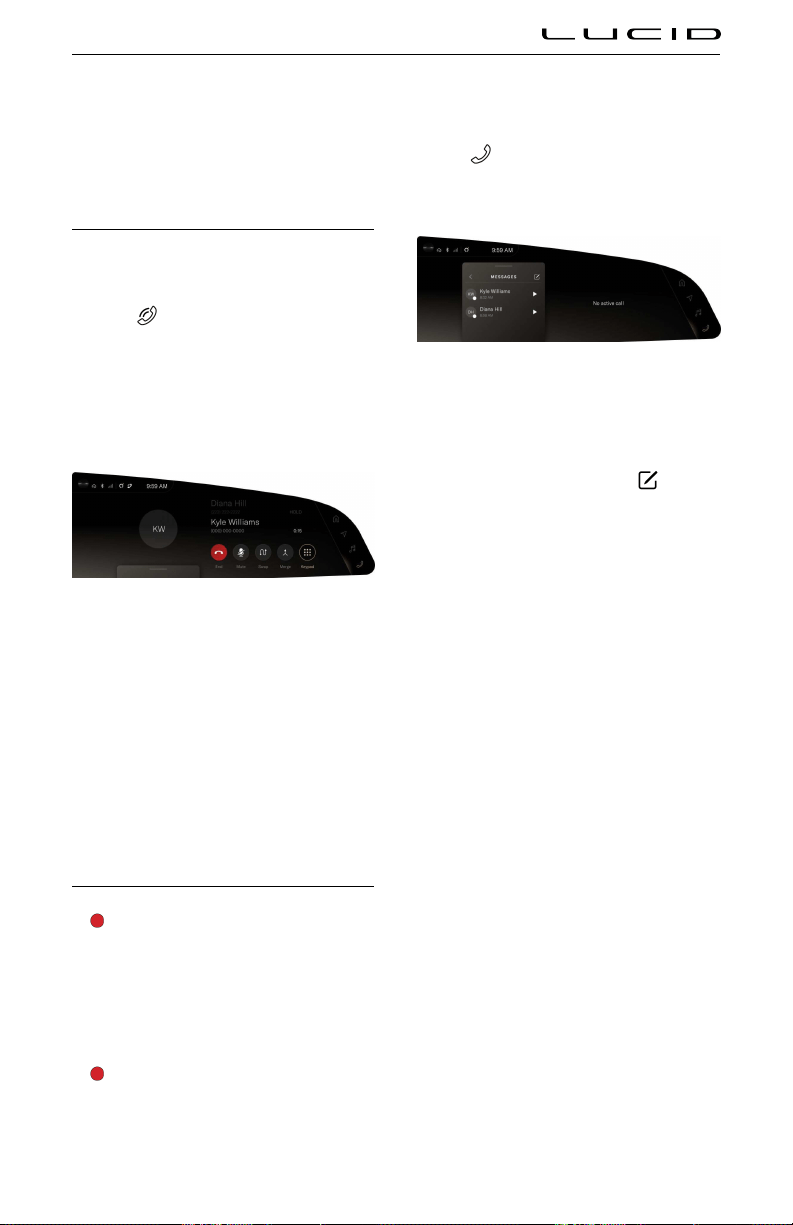
Press an option on the touchscreen or use the
steering wheel controls to DECLINE or ACCEPT
the call.
Note: Your phone may prompt you to select the
audio output for the call, depending on the type
of phone and last output used.
In-Call Options
Active calls are displayed on the right Cockpit
Panel.
- The
active call icon will be displayed
in the status bar when a call is in
progress.
- Contact information and call length will
be displayed in the main screen, along
with call control buttons.
If a call is placed on hold and a second call is
made, the call control buttons change.
- Press Swap to switch between the active
call and the call on hold.
- Press Merge to bring both callers into a
shared call.
Call volume and the mute option can be
controlled with the physical controls in your
vehicle. See Physical Media Controls on page
123.
Using Messages
WARNING: Distracted driving can lead
to loss of vehicle control and a collision,
which can result in serious injury or
death. Lucid strongly recommends that
the driver stay focused on the road at
all times while driving. Safe operation
of the vehicle is the driver’s primary
responsibility.
WARNING: Always ensure you are
following all applicable local laws
regarding the use of phones while
driving. This includes, but is not limited
to, laws that prohibit texting and require
hands-free phone operation at all times.
Tap the
phone icon on the right Cockpit
Panel to open the phone smart drawer and
select MESSAGES.
Unread messages will be indicated by a dot,
which will disappear once a message is played
back. Press a message to have it read aloud,
and press again to stop playback.
To send a new message, press the
compose icon. Select the recipient and the
preset message, then press SEND.
Incoming Messages
Incoming messages from a paired phone will
display an alert on the right Pilot Panel. If
your phone contacts have been synced to
the vehicle, any applicable contact information
will be displayed. See Syncing Contacts and
Messages on page 131.
Press an option on the touchscreen or use the
steering wheel controls to PLAY the message,
CALL the sender, or REPLY with a preset
message.
Infotainment 133

Connecting the Vehicle to Wi-Fi®
Add a New Wi-Fi Network
Your vehicle can be connected to a Wi‑Fi
network in order to send and receive data,
which is often faster than cellular networks.
Lucid recommends leaving Wi‑Fi enabled and
connected to a network whenever possible,
so as to receive software updates in a timely
manner.
Note: Connecting to a Wi-Fi network may result
in large amounts of data being transferred
to/from the car. Lucid is not responsible for
any overages or charges related to such Wi-Fi
usage.
To connect to a network:
1. On the Pilot Panel, select
>
Connectivity > Wi-Fi® .
2. When Wi‑Fi is enabled, the system scans
for available networks in range. Under
OTHER NETWORKS, select the network
you wish to use, enter a password if
prompted, and press JOIN.
3. If the connection succeeds, the name
appears under CONNECTED NETWORK.
Added networks not currently connected are
listed under SAVED NETWORKS. Tap a network
name to connect to it.
Edit or Remove a Wi-Fi Network
1. Press the three dots next to a network to
view its properties.
2. From here you view network information,
or press FORGET NETWORK to remove it
from your list.
Wi-Fi Quick Access
On the right Cockpit Panel, press the status bar
to expand it, then press the
Wi‑Fi icon to
open its menu.
From this menu, you can:
- Tole Wi‑Fi on/off
- View the currently connected network
- Press to switch to a saved network
- Press
Wi-Fi® SETTINGS to open that
screen on the Pilot Panel
Infotainment 134
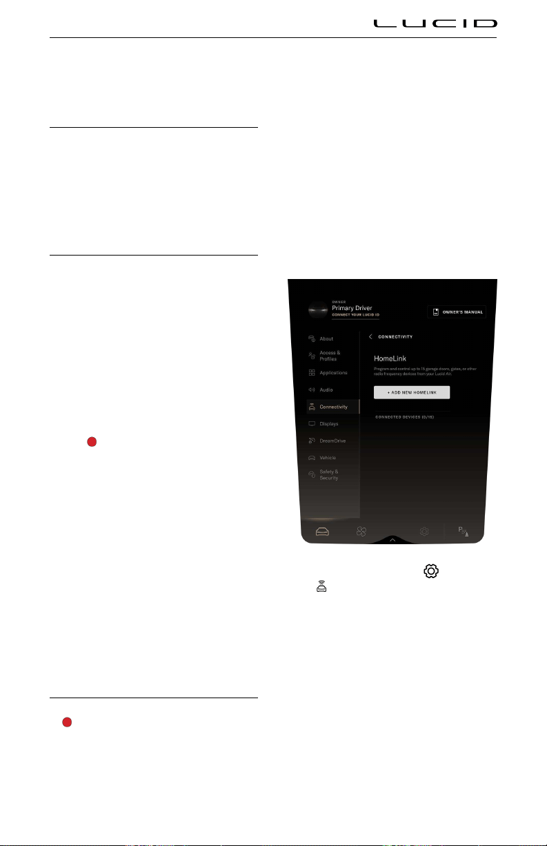
HomeLink
What is HomeLink?
HomeLink is a wireless control system that
enables you to remotely operate up to 15 Radio
Frequency (RF) devices, such as garage doors,
gates, lights, and home security systems.
Additional system information can be found
online at www.homelink.com.
HomeLink FCC/ISED Advisory
This device complies with Federal
Communications Commission (FCC) rules part
15 and Innovation, Science, and Economic
Development Canada RSS-210. Operation is
subject to the following two conditions:
1. This device may not cause harmful
interference,
2. This device must accept any interference
that may be received including
interference that may cause undesired
operation.
WARNING: The transmitter has
been tested and complies with
FCC and ISED rules. Changes
or modifications not expressly
approved by the party responsible
for compliance could void the
user’s authority to operate the
device.
This equipment complies with FCC and ISED
radiation exposure limits set forth for an
uncontrolled environment. End Users must
follow the specific operation instructions
for satisfying RF exposure compliance. This
transmitter must be at least 20 cm (8 in)
from the user and must not be co-located
or operating in conjunction with any other
antenna or transmitter.
Programming HomeLink
WARNING: Do not use HomeLink with
any garage door opener that cannot
detect an object and signal the door
to stop and reverse as required by U.S.
Federal Safety Standards (including
any garage door opener manufactured
before April 1st, 1982). A garage door
opener which does not have the safety
stop and reverse feature does not meet
current federal safety standards. Using
a garage door opener without these
features increases the risk of serious
injury or death.
To set up a new HomeLink program, have the
remote for the garage door or gate you are
programming ready, and follow these steps:
1. On the Pilot Panel, select >
Connectivity > HomeLink, then press
+ ADD NEW HOMELINK.
Note: Press CANCEL during any step
of programming to return to the main
HomeLink® screen. No information will
be stored.
2. Use the on-screen keyboard to enter a
name for your HomeLink®, then press
CONTINUE.
3. Prepare your surroundings as instructed
on the screen, and press CONTINUE
when you are ready to proceed.
Note: Select Program with D-Mode
only if your device requires D-Mode
Infotainment 135

programming per the HomeLink website
or operator’s manual.
4. To record the remote signal, press and
hold the remote 2 in (5 cm) below the
letter L on the front of your vehicle until
the horn sounds and the headlights flash.
5. Once the Pilot Panel shows that recording
is completed, press CONTINUE.
Note: If the on-screen process detects
that your device uses a fixed code, it will
automatically skip this step and proceed
to the test in the next steps.
6. To train the receiver, press the LEARN
button on the back of your receiver
(removing the cover if needed), then press
CONTINUE on the Pilot Panel.
Note: Because pressing the LEARN
button is time-sensitive, a second person
can assist with this step.
Note: If your receiver is QuickTrain
compatible, you can press CONTINUE.
Note: After pressing the 'LEARN' or
sync button, you will have 30 seconds
to test HomeLink. If a signal is not
detected within the timeout period, an
error message will be displayed with the
option to try again.
7. To test, press the TEST HOMELINK
button. You will need to press this three
times in total. Wait until you see a check
mark before pressing the button a second
and third time.
8. During each brief test, the TEST
HOMELINK button will be temporarily
unavailable, while the current test number
animates to indicate it is in progress.
Note: The device you are programming
may respond during any of these three
tests. Continue with all three tests.
9. After a test completes, a check replaces
the number and the TEST HOMELINK
button becomes available. Continue
through all three tests.
10. After all three tests have completed, the
screen will prompt you to confirm whether
the device responded. Press
YES or NO.
Note: Pressing NO will give you the option
to restart the test and contact information
for HomeLink Help.
11. If you pressed
YES, you will be brought
back to the Connectivity screen. Your
new HomeLink device will be listed under
CONNECTED DEVICES.
Reprogramming a device
1. On the Pilot Panel, select
>
Connectivity > HomeLink, then select
the device to be reprogrammed.
2. On the device details screen, press
PROGRAM.
3. Follow the steps for programming a
device. See Programming Homelink.
Using HomeLink®
Once devices have been programmed to your
vehicle, they can be accessed using the
HomeLink menu on the right Cockpit Panel.
The HomeLink menu will open automatically
when the vehicle is detected within 82 ft (25 m)
of a programmed garage door or gate. To access
it manually:
1. Press the status bar to expand.
2. Press
to open HomeLink.
From this menu, you can:
- Press + ADD NEW HOMELINK to add a
new device. See Programming HomeLink.
- Press HOMELINK SETTINGS to edit or
remove existing devices. See Renaming or
Deleting a Device.
- Press a device name to activate it.
The icon next to a device indicates that a
signal has been sent to the door or gate. The
menu automatically collapses 3 seconds after a
signal is sent.
Renaming or Deleting a Program
Note: For your security, it is recommended to
delete all programmed devices upon the sale or
lease termination of your vehicle.
Renaming a program
1. On the Pilot Panel, select
>
Connectivity > HomeLink, then select
the device to be renamed.
Infotainment 136

2. On the device details screen, press the
edit icon.
3. Use the on-screen keyboard to edit the
device name, then press SAVE to confirm,
or CANCEL to return to the previous
screen.
Deleting a program
1. On the Pilot Panel, select
>
Connectivity > HomeLink, then select
the device to be removed.
2. On the device details screen, press
DELETE.
3. The screen will prompt to confirm
whether you wish to delete the selected
device. Press DELETE ALL to confirm, or
CANCEL to return to the previous screen.
Deleting all programs
1. On the Pilot Panel, select
>
Connectivity > HomeLink.
2. If two or more devices are connected to
your vehicle, the option to DELETE ALL
will be available. Press it to continue.
3. The screen will prompt to confirm
whether you wish to delete all connected
HomeLink® devices. Press DELETE ALL
to confirm, or CANCEL to return to the
previous screen.
Infotainment 137

Vehicle Information
Vehicle Identification Number
On the Pilot Panel, select > About
Vehicle to view the VIN.
Direct Access to the Owner's Manual
You can access the Owner's Manual via the
Pilot Panel under Settings. The Owner's Manual
periodically updates with the latest information
as long as the vehicle has internet connectivity.
Select
> About Vehicle on the Pilot
Panel, then press the OWNER’S MANUAL
button.
Note: You can also view the Owner’s Manual
with the Lucid mobile app.
Alerts and Notifications
WARNING: Read all alerts and
notifications carefully and follow any
provided instructions as soon as
possible. Do not drive the vehicle if you
are cautioned not to do so.
Important system alerts and notifications that
appear on the Instrument Cluster will also be
saved under the About Vehicle screen on the
Pilot Panel for later reference.
On the Pilot Panel, select
> About
Vehicle to view any current alerts and
notifications.
Note: A dot on the
About Vehicle
icon indicates a new alert or notification.
The indicator will disappear once the alert or
notification has been reviewed.
If you are unsure of how to resolve an alert or
notification, contact your Lucid Customer Care
for assistance.
Infotainment 138

Software Updates
Current Software Version
On the Pilot Panel, select > About
Vehicle to view the current software version.
Press Learn More next to a version to read the
release notes.
Updating Software
Your vehicle supports wireless software
updates, giving you continued access to new
features and improvements. Lucid recommends
installing these updates as soon as they
become available.
Current Software Version
On the Pilot Panel, select
> About
Vehicle to view the current software version.
Press Learn More next to a version to read the
release notes.
Prerequisites for updates
- Your vehicle must be shifted into P (Park)
before starting an update.
- Because some updates can take a few
hours to install, the vehicle battery must
be charged to at least 20% before
installation. See Charging the Vehicle on
page 145.
Note: Charging is paused during the
update installation process.
- Ensure that your vehicle is connected
to Wi-Fi® and has a strong signal in
order to receive updates quickly and
uninterrupted. See Wi-Fi Quick Access on
page 134.
- During the update, you will not be able
to lock or unlock the vehicle, access the
screens, or drive.
- Guest Users are not able to install
or schedule updates. See
About User
Profiles on page 118.
CAUTION: All occupants must exit the
vehicle before the update. Once the
update starts, you will not be able lock
or unlock doors.
Update notifications
When a software update becomes available,
you should receive notifications in three ways:
1. A push notification will be sent to the
Lucid mobile app.
Note: This notification will only be
received if push notifications are enabled
on your mobile device.
2. A notification will display on the right
Cockpit Panel when your vehicle is
shifted into
P (Park).
If the update is not installed within
24 hours from the first notification, then
notifications continue once per day at the
start of the first trip of the day.
Press REMIND ME LATER to postpone
the notification for 8 hours. Press
REVIEW UPDATE to continue with the
update process on the Pilot Panel.
3. On the Pilot Panel, a notification badge
will appear on the
icon. Once the
update is installed, the badge will
disappear.
Infotainment 139

View available Update
On the Pilot Panel, select
>
About Vehicle. If a software update is
available, a notification badge will appear
on the
About Vehicle icon. The update
information, estimated installation time, and
options will be displayed.
Schedule an update
On the software update screen, press
SCHEDULE TIME if you wish to start the
update later. Updates can be scheduled up to
48 hours later.
1. Read the cautionary statement and press
CONFIRM to consent to the update.
2. Select the time to start on the screen
provided and press SET TIME to save.
3. Your scheduled date and time will be
displayed on the main software update
screen, and can be edited by pressing the
icon beside it. Ensure that all update
prerequisites will be met at the scheduled
time.
30 minutes before a scheduled update, you
will receive a notification on the right Cockpit
Panel, with options to DELAY AN HOUR or
CANCEL SCHEDULE.
Install an update now
On the software update screen, press
INSTALL NOW to proceed with the update.
1. Read the cautionary statement and press
CONFIRM to consent to the update.
2. The system will perform a series of
checks to ensure all prerequisites have
been met.
3. A 2-minute countdown will display. Exit
and lock the doors at this time. See Doors
on page 29.
4. During the update, the Pilot Panel and
left Cockpit Panel screens will be blank.
The Instrument Cluster will indicate the
update is proceeding. The progress can
be viewed on the right Cockpit Panel and
within the Lucid mobile app.
5. When the update is complete, a
notification will appear on the left Pilot
Panel and a push notification will be sent
to the Lucid mobile app.
Note: If an update fails to install, a notification
will display on the Infotainment screens and a
push notification is sent to the Lucid mobile
app.
- If a failure was due to a prerequisite
not being met (e.g., battery was at less
than 20% or vehicle was not put in Park),
resolve the issue and press TRY AGAIN.
- If a failure was due to another reason,
contact a Lucid Service Center for
assistance.
Viewing Release Notes
Lucid strongly recommends that all users read
the release notes for every software update.
They can contain important information about
your vehicle, including safety information or
new operating instructions.
Release notes can be viewed before and after a
software update:
- On the Pilot Panel, select
>
About Vehicle. The software versions
for the current installation and any
available updates will be listed. Press
Learn More next to a version to read the
notes for it.
- When an update has installed
successfully, press Learn More on the
prompt that appears on the right Cockpit
Panel.
Infotainment 140

Electric Vehicle Components
High-Voltage Components
WARNING: The high-voltage system in this vehicle has no user-serviceable parts. Do not
disassemble, remove, or replace high-voltage components, connectors, or cables. High-voltage
cables are colored orange for easy identification.
WARNING: In the unlikely event that a fire occurs, exit the vehicle and immediately contact
your local fire emergency responders.
WARNING: For your safety, always read and follow the instructions and warnings written on all
labels attached to your vehicle.
1. Front Inverter
2. High-voltage cables (not all high-voltage cables are shown)
3. Front Drive unit
4. Wunderbox
5. Charge port
6. Battery pack
7. Rear drive unit
8. Rear inverter
High-Voltage Battery Pack & Charging 141

This symbol can be found on high-voltage components and indicates risk of electrical shock.
High-Voltage Battery Pack & Charging 142

Battery Information
About the Vehicle Batteries
WARNING: Only a Lucid Service Center
should service the high-voltage battery
pack. Improper handling can result in
death or serious injury.
There are two types of batteries powering your
vehicle: a high-voltage lithium ion battery pack
that powers the vehicle's electric powertrain
motors and two 12V AGM batteries that power
systems such as the infotainment displays and
safety systems.
Environmental: Please recycle in accordance
with local regulations.
High Voltage Battery Pack Care
Storage temperature
CAUTION: Avoid exposing your vehicle
to ambient temperatures above 113°F
(45°C) or below -4°F (-20°C) for more
than 24 hours at a time. Prolonged
exposure can greatly reduce battery
pack life and performance. If it is
necessary to exceed these guidelines,
whenever possible plug the vehicle in
to a charging source to provide reliable
thermal conditioning of the battery
pack.
Extreme temperatures can damage the battery
pack. If possible, avoid parking in direct
sunlight, especially on hot, sunny days. Lucid
also recommends that you keep your vehicle
sheltered or parked in a garage whenever
possible in extremely cold weather.
Preserving high voltage battery pack health
The most effective way to prolong the battery
(when not driving) is to leave it plued into
a charging source. Setting the charge level to
"Daily" usage helps preserve battery health.
CAUTION: When the vehicle is not
in use for long periods of time, it's
necessary to plug into a charging
source and set the charge target to the
minimum "Daily" value.
When your vehicle is left idle and unplued,
the battery pack gradually discharges over
time. Allowing the battery pack to completely
discharge to 0 mi/0 km could cause permanent
damage. Battery pack life and performance are
greatly improved by maintaining a healthy state
of charge (generally between 40% and 80%).
When the remaining battery pack
charge falls below the 50 mi/80 km
range, the Cockpit Panel shows a
yellow low battery indicator.
When the battery pack charge level falls below
10 mi/16 km, warnings display on the Cockpit
Panel. Proceed to the nearest charging station
as soon as possible in order to avoid a vehicle
shutdown.
When poor battery pack health is detected, the
Cockpit Panel displays a warning indicator.
As is normal with all lithium-ion batteries,
battery pack performance degrades over time.
When the battery pack needs service, the
Pilot Panel displays a warning and you should
contact Lucid Customer Care to schedule
service.
High-Voltage Battery Pack & Charging 143
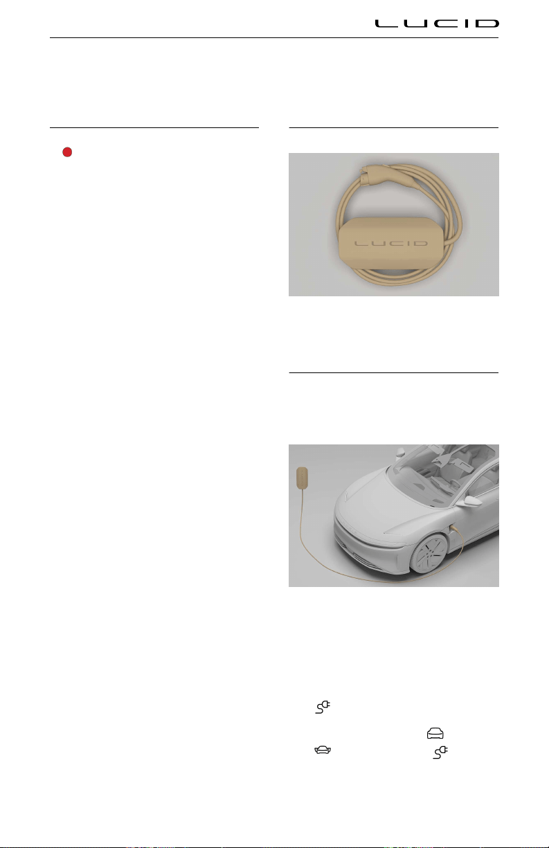
Charging Instructions
Safety Checklist
WARNING: If you have any concerns
with the condition of a wall outlet, the
charge port or the charging cable, DO
NOT use them. Seek assistance from a
qualified electrician or a Lucid Service
Center.
Before charging your vehicle, check the
following items:
- If using a domestic wall outlet, inspect
the outlet and do not use it if it appears
damaged or worn.
- Inspect the charging cable and connector
for damage, including frays or cracks. If a
part appears damaged, do not use it.
Note: If the Lucid Mobile Charging Cable
is damaged, contact a Lucid Service
Center.
- Ensure that the charging cable is fully
uncoiled before use.
- Check that the charging connector and
charge port are clean and unobstructed.
If you find any contamination or a foreign
object in either part, do not use them and
contact a Lucid Service Center.
- Check that the charging cable and charge
port are dry. Ensure that your hands are
dry, and there is no water or other fluids
in the surrounding area (such as puddles
on the ground).
Lucid Mobile Charging Cable
Your vehicle is supplied with a Lucid Mobile
Charging Cable kit, which is stored in the trunk.
Charge Port Door
The charge port door is located to the rear of
the left front wheel.
Opening and closing the door
Car doors must be unlocked for the charge port
to open. You can open and close the charge
port door using any of the following methods:
- On the left Cockpit Panel, press the
charge port icon.
- On the Pilot Panel, select >
DOORS and press the charge
port icon.
High-Voltage Battery Pack & Charging 144

- On the Pilot Panel, select >
ENERGY and press the OPEN
CHARGE PORT button.
- Use the Lucid mobile app.
- With a valid key fob detected within
6.5 feet (2 m) of the unlocked vehicle,
press the bottom of the charge port
door and it will open automatically. The
charge port door automatically closes
after unpluing the charging cable;
otherwise, you can gently push upward
on the bottom of the door until automatic
closing takes over.
CAUTION: If the charge port door has
iced over in cold weather conditions,
DO NOT attempt to break the ice using
blunt force (that is, hitting or chipping
at it with a tool), as this could cause
damage.
Note: If the charge port door has iced
over, Lucid recommends using the in-vehicle
controls or the Lucid mobile app to cycle the
open/close function of the door until the ice
breaks.
Manually opening the door
CAUTION: Manually opening the charge
port door is only recommended in
instances where the vehicle has no
power and the 12V batteries cannot be
charged.
If the vehicle has no power, the charge port
door can be opened manually:
1. Open the driver’s door.
2. Place your finger at the bottom right
corner of the charge port door and gently
lift up.
3. Continue lifting on the corner until a gap
begins to form between the top edge and
the fender.
4. Once there is a gap along the top edge,
insert your fingers into the gap and
gently pull downward until a hard stop is
reached.
Charging the Vehicle
Plug the charging cable into the charge port.
Note: During charging, the battery system’s
heating and cooling functions monitor the
temperature of the battery pack, and will turn
on or off as needed to help maintain an ideal
temperature. Clicking or fan noises are normal.
Errors during charging
If an error occurs, the charge port light turns
red. If this happens, details and instructions
will be displayed on both the Pilot Panel and
the Cockpit Panel.
If following the steps in the displayed
instructions does not resolve the error, contact
Lucid Customer Care for further assistance.
Stopping charging
To stop charging before the process is
completed, press the STOP CHARGING button
on the
ENERGY screen of the Pilot Panel.
You can also stop charging using the Lucid
mobile app.
Disconnecting the Charging Cable
Once charging is completed, unlock the door
doors, press the button on the charging cable,
and pull the charging cable to disconnect it
from the charge port.
High-Voltage Battery Pack & Charging 145
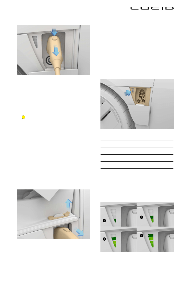
Note: The vehicle cannot be driven when the
charging cable is connected to the charge
port. If you attempt to shift out of P (Park),
a notification will appear on the Instrument
Cluster.
Emergency manual charging cable disconnect
CAUTION: Manually releasing the
charging cable is only recommended
in instances where the charging cable
button will not release it from the
charge port.
If pressing the button on the charging cable
will not release it, the vehicle has a manual
disconnect:
1. Open the hood. See Hood Opening and
Closing.
2. Pull up on the manual disconnect lever to
release the charging cable.
3. Make sure to correctly insert the manual
disconnect lever to its original position
before closing the hood.
Charging Status
You can check the progress of the charging
process via the light on the charge port, the
in-vehicle displays, or the Lucid mobile app.
Charge port light
The charge port light indicates the current
charging status. Refer to the following table to
understand the meaning of each light color and
pattern.
Color Definition
White (Solid) Ready to charge
White (Flashing) Charging pending
Green (Flashing) Charging in progress
Green (Solid) Charging completed
Red (Solid) Charging error
During charging, the progress meter of the
charge port light flashes green, indicating the
current charge level of the battery pack.
1. 0% - 24%
2. 25% - 49%
High-Voltage Battery Pack & Charging 146

3. 50% - 74%
4. 75% - 99%
When charging is completed, the light will
remain solid green.
Vehicle display status
Once charging begins, the Pilot Panel and the
Cockpit Panel will both display the current
charging status, including time remaining to
completion.
Cockpit Panel charging display
Setting a Charge Limit
CAUTION: Charging beyond the
recommended level too often can cause
battery pack degradation.
Without a set charge limit, the charging system
will charge the battery to the recommended
level. The vehicle dynamically adjusts the
actual charging rate depending on the state
of charge, ambient temperature, battery pack
temperature, and position of the charge slider.
You may need to adjust the charge limit higher
or lower according to your driving needs. A
higher charge limit will increase trip distance.
Vehicles that are parked for extended periods
should be plued in and use a lower charge
limit to maintain battery pack health.
Follow these guidelines for setting the charge
limit:
- For the fastest possible charge rate
(miles/minute), set the slider as low as
practically possible for the intended use
of the vehicle.
- For general use, set the slider to "Daily"
or 50% - 80%. This setting best preserves
the battery pack life.
- For more range, set the slider beyond
"Daily" and up to "Distance." "Distance"
allows a full charge.
When charging beyond the "Daily" setting, you
may notice changes in reduced regenerative
braking and charging speeds. This functionality
gradually returns as the car is driven.
To set the charge limit:
1. On the Pilot Panel, select
>
ENERGY to display charging options.
2. Press the SET CHARGE LIMIT button.
3. Use the slider to set the desired level
of charge between 50% - 100%. Set
the slider to Daily for general use and
Distance for a long-range trip.
4. Press the DONE button.
Cold Weather Charging Considerations
CAUTION: Do not expose your vehicle
to extreme temperatures for long
periods without driving or connecting
to a charging cable, as this can
negatively affect battery pack life.
When temperatures are below 41°F
(5°C) and you are not driving your car,
connect to a charging cable.
In very cold weather you may experience
a range reduction. The Pilot Panel will
automatically switch to the
ENERGY
screen, dispaying the reduction and remaining
range.
When the battery pack is too cold
and needs to reserve energy, a blue
battery warning indicator will be
displayed on the Instrument Cluster.
High-Voltage Battery Pack & Charging 147

Maintenance Requirements
Your Responsibility
The safety, reliability, and performance
of your vehicle depends partly on how
well it is maintained. Maintenance is an
owner's responsibility, and you must ensure
appropriate vehicle upkeep according to Lucid's
recommendations.
Scheduled Maintenance
Your vehicle will display a message on the
Instrument Cluster when the annual scheduled
maintenance is due.
Lucid recommends entrusting a Lucid Service
Center to perform the majority of the regular
servicing and maintenance of your vehicle.
Lucid Service Centers have the specialized
knowledge and equipment necessary to ensure
the best possible service and care for your
vehicle.
Fluid Replacement
Lucid Service Centers will replace the
necessary fluids in your vehicle during regularly
scheduled service intervals.
Owner Maintenance
WARNING: Some fluids used in electric
vehicles are poisonous and should
not be consumed or brought into
contact with open wounds. These
fluids include brake fluid, battery acid,
battery coolant, and windshield washer
additives. Always read and obey all
instructions printed on fluid container
labels.
WARNING: Any significant or sudden
drop in fluid levels or uneven tire wear
should be rectified immediately.
In addition to scheduled maintenance
performed by Lucid, you must carry out a
few simple checks more frequently. Details are
provided in the remainder of this section.
Daily checks
- Look for fluid deposits underneath the
vehicle that might indicate a leak.
Note: A small puddle of water may collect
under the vehicle if the air conditioning
has been running, which is normal.
- Check the charge level of the battery
displayed on the Instrument Cluster. See
Battery State of Charge Indicator on page
67.
- Check the operation of the seat belts,
horn, wiper and washer, turn signals, and
all exterior lights.
- Check the operation of the brakes
and ensure that the parking brake
automatically engages when the vehicle is
in P (Park).
Monthly checks
- Check the windshield washer fluid level
and top off if needed. See Checking
Washer Fluid on page 154.
- Turn on the air conditioning to
ensure that it is working properly. See
Temperature Control on page 86.
- Check the pressure, wear, and condition
of each tire. Check the vehicle mileage to
determine whether the tires are due to be
rotated. See Maintaining Tire Pressures
on page 179.
WARNING: If you discover
abnormalities during these checks,
such as uneven tire wear or a sudden
drop in fluid levels, contact Lucid
immediately.
Electrical and High Voltage Safety
WARNING: Always disconnect the
charging cable before working
underneath the vehicle or the hood,
regardless of whether or not it
is charging. See Disconnecting the
Charging Cable on page 145.
Maintenance 148

WARNING: Some cooling fans operate
even when the vehicle is powered off.
Keep hands, hair, clothing, and tools
clear of the fan blades at all times.
While your vehicle was built with the safety
of you and your occupants as first priority,
it is important to be aware of the risk of
injury associated with high-voltage systems and
protect yourself accordingly.
- Read and follow the directions on all
safety labels attached to the vehicle.
- There are no user-serviceable parts in
your high-voltage system. Do not attempt
to access the high-voltage system or
disassemble, remove, or replace any
system components. All high-voltage
cables are colored orange for easy
identification.
- In the event of a collision, never touch
any high-voltage wiring, connectors, or
components connected to the wiring,
even if you think the vehicle may not
be powered on. There is a risk of fatal
injury by electrocution if the system’s high
voltage is still active.
- Should a vehicle fire occur, immediately
evacuate the vehicle and contact your
local fire emergency responders, as
they possess the proper training and
equipment to safely extinguish fires in
electric vehicles.
Maintenance 149

Maintenance Schedule
The scheduled maintenance or service must be performed in accordance with the chart below to keep
your vehicle in top operating condition.
The service intervals in this maintenance and service schedule are based on average driving
conditions. Some items will need more frequent service if you drive in unique conditions, such as
unusually wet or dusty areas. For recommendations applicable to your individual needs and usage,
consult your Lucid Service Center..
Note: Bring your charging cable and all key fobs with you to every service appointment to be checked
during the multi-point inspection.
Maintenance Items Every 1 year or
12,000 miles
Every 2 years or
24,000 miles
Other
Multi-point inspection •
Tire rotation and tire balance (19 inch
wheels only)
•
Cabin air ilter replacement (2)
•
More often under unique
conditions
Brake luid replacement
•
More often under unique
conditions
Key fob battery replacement •
Sun visor battery replacement •
Wiper blade replacement •
Air conditioning performance check •
Battery heath check
•
12V Battery replacement (2) Every 4 years or 48,000
miles
Tire repair sealant replacement Every 5 years or 60,000
miles
Coolant check Every 3 years or 36,000
miles
Maintenance 150

Multi-Point Inspection
Your vehicle should be given a full multi-point
inspection service every 12 months or 12,000
miles, whichever comes first.
Note: A message will be displayed on the
Instrument Cluster as a reminder when it is
time to service your vehicle.
This service includes inspections and checks
for the following systems:
- Steering alignment
- Battery (12V) condition
- Battery pack (HV) condition
- Coolant condition
- Brake fluid condition
- Brake rotors and pads wear
- Chassis bolts torque
- Closures (doors, hood, and trunk)
operation
- Condenser (check for debris)
- Electronic parking brake operation
- Heating, ventilation, and air conditioning
operation
- Horn
- Interior and exterior lights
- Key fob operation
- Seat belts operation
- Tire pressure and tire wear
- Visual signs of fluid leaks
- Wipers and washers
- Charging system and charging cable
- Firmware
Your vehicle will also be given a road test to
inspect its current driving condition (such as
pedal operation, vehicle handling, and steering
alignment) and to check for any abnormal
operational noises.
Maintenance 151

Maintenance Panel
Under Hood Rear Apron
In order to be able to access some of the
serviceable components on your vehicle, the
under hood rear apron must be removed.
Removing the panel
CAUTION: Take care not to damage the
emergency responder cut loop when
removing the panel. See Emergency
Responder Cut Loop on page 201.
1. Lift the rear edge of the panel.
2. Release the ten clips securing the panel
to the body.
3. Release and remove the access panel.
Installing the access panel
CAUTION: When reinstalling the under
hood rear apron, make sure the panel
is correctly seated, as it protects the
internal components from water.
Installation is the reverse of the removal
procedure.
The emergency responder cut loop label must
be visible after the maintenance panel is
installed.
Maintenance 152
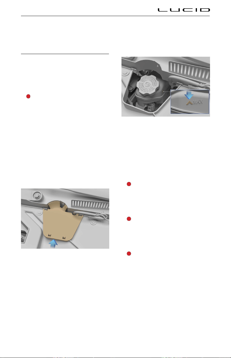
Fluid Reservoirs
Checking Brake Fluid
Low brake fluid warning indicator
If the fluid in the brake reservoir drops below
the recommended level, the brake warning icon
will be displayed on the Instrument Cluster.
This will be accompanied by a notification
message.
WARNING: If the low brake fluid
notification displays while driving, stop
as soon as safety permits by gently
applying the brakes. Do not continue
driving. Contact a Lucid Service Center
immediately.
Checking the fluid level
Check the brake fluid level with the vehicle on
level ground.
1. Remove the under hood rear apron. See
Under Hood Rear Apron.
2. Remove the brake reservoir cover.
3. Check the fluid level visually by looking
at the outside marks on the side of the
reservoir without removing the filler cap.
The brake fluid level should always be
between the MIN and the MAX marks.
Note: Although brake fluid level drops
slightly during normal use as a result of
brake pad wear, it should not drop below
the MIN mark. Excessive or frequent fluid
loss may indicate a leak in the system.
Topping off brake fluid
WARNING: Only use new fluid from a
sealed, air-tight container. Never use
previously used fluid or fluid from a
previously opened container. Excess
moisture in the brake fluid can cause
a dangerous loss of braking efficiency.
WARNING: Brake fluid is highly
toxic. Keep containers sealed and
out of the reach of children. If
accidental consumption of brake fluid
is suspected, seek immediate medical
attention.
WARNING: Do not allow brake fluid to
come into contact with your eyes. If
this happens, flush your eyes with clean
water for at least 15 minutes and seek
immediate medical attention.
To top off the fluid:
1. Clean the filler cap before removing to
prevent dirt from entering the reservoir.
2. Unscrew the cap and remove.
Maintenance 153

3. Fill the reservoir to between the MIN and
the MAX marks using a clean funnel and
brake fluid meeting specification DOT4.
4. Install the reservoir cap.
CAUTION: Brake fluid will damage
painted surfaces. Immediately soak up
any spills with an absorbent cloth and
wash the affected area with a mixture
of car shampoo and water.
Replacing brake fluid
The brake fluid should be replaced every 2
years or every 24,000 miles, whichever comes
sooner.
Checking Washer Fluid
Check the level of the washer fluid monthly, or
more frequently if you use it often.
If the quantity of fluid remaining
in the washer reservoir drops below
the recommended level, an indicator
will be displayed on the Instrument
Cluster. This will be accompanied by a
notification message.
Operate the washers periodically to check that
the nozzles are clear and properly directed.
If a washer jet performs poorly, see Cleaning
Washer Jets.
Topping off washer fluid
WARNING: In temperatures below
4°C (39°F), use a washer fluid with
deicer. In cold weather, using a washer
fluid without deicer can cause the
fluid to freeze on contact with the
windshield, impairing visibility. .
Note: Some national or local regulations restrict
the use of Volatile Organic Compounds (VOCs).
VOCs are commonly used as antifreeze in
washer fluid. Use a washer fluid with limited
VOC content only if it provides adequate freeze
resistance for all climates in which you drive.
1. Clean the filler cap before opening to
prevent dirt from entering the reservoir.
2. Open the filler cap.
3. Fill the reservoir until the fluid is visible
just below the filler neck.
4. Close the filler cap.
CAUTION: Washer fluid can damage
painted surfaces. Wipe up any spills
immediately with an absorbent cloth
and wash the affected area with water.
Maintenance 154
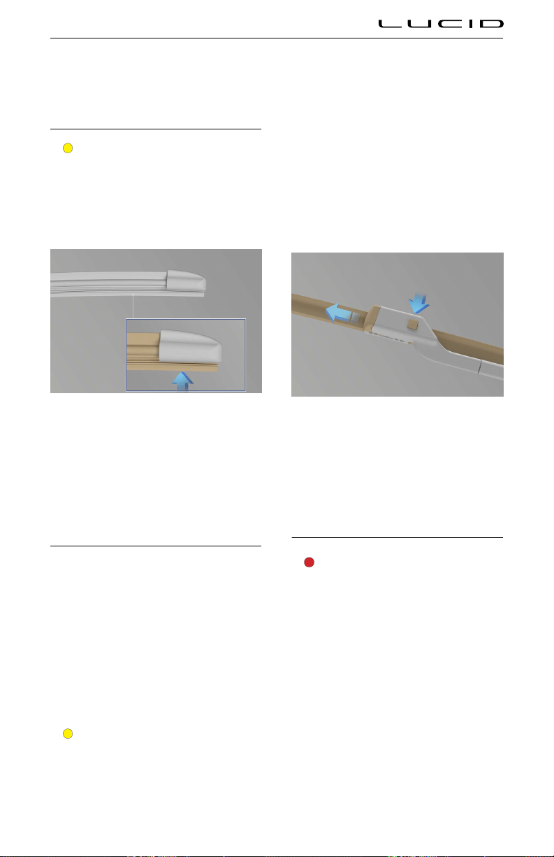
Wiper Blades and Washer Jets
Checking the Wiper Blades
CAUTION: Only use cleaning products
that have been approved for use
on automotive glass and rubber.
Inappropriate products may cause
damage, smearing, or increased glare
on the screen.
You should periodically check and clean the
wiping edge of the wiper blade. Clean the
blade edge using a soft cloth or sponge,
and isopropyl (rubbing) alcohol or windshield
washer fluid.Also, check the blade rubber for
cracks, splits, or roughness. If any damage is
found, replace the blade immediately to prevent
damage to the glass.
Replacing Wiper Blades
Note: For optimum performance, replace the
wiper blades at least every year.
Life expectancy of wiper blades can vary,
depending on geographical area and frequency
of use. Poor wiper blade performance can
result in “chattering” (that is, skipping across
the glass), or leaving behind marks, streaks of
water, or wet spots. If any of these conditions
are present, clean the wiper blades or replace
them as needed.
Replacing the front wiper blades
CAUTION: Only install wiper blades
that are the same length and identical
to the original specification. Failure to
do so may cause poor performance and
damage to the wiper system.
1. Open the hood. See
Hood Opening and
Closing.
2. Lift the wiper arm away from the
windshield.
3. Depress the locking tab while sliding
the wiper blade away from the arm and
remove.
4. Installation of the new wiper blade is the
reverse of removal. You should be able to
hear and feel it click into place on the
wiper arm.
5. Gently lower wiper blade back on to the
windshield.
Cleaning Washer Jets
WARNING: Do not operate the washer
jets during cleaning. Windshield washer
fluid may cause irritation to the eyes
and skin. Always read and observe
the washer fluid manufacturer’s
instructions.
Because the washer jets are located on the
wiper arms, it is easier to clean them by
opening the hood first. See Hood Opening and
Closing.
Maintenance 155

If a washer jet nozzle becomes cloed
with debris or build-up, its performance can
be reduced. There are several methods for
removing any blockage:
- Dip a small, soft-bristled brush (such as
an old toothbrush) in warm water and
scrub in and around the nozzle to clear
away any dirt or debris.
- Use a can of compressed air to blow a
concentrated stream of air into the clog
to loosen it, and to blow away any debris
from the nozzle.
- For more serious clogs, slide a thin piece
of wire into the nozzle to clear any
blockages.
Maintenance 156

Cabin Air Filter
Replacing the Cabin Air Filters
Your vehicle has two cabin air filters installed
that prevents pollen, industrial fall-out, road
dust, and other particles from entering the
vehicle via the vents.
The cabin air filters should be replaced every
year or every 12,000 miles, whichever comes
sooner. Failure to replace the air filters will
result in reduced air flow into the vehicle.
Note: To gain the maximum benefit of the cabin
air filters, it is suested the filters are changed
prior to the pollen season.
Note: If you operate your vehicle in an
environment where there is more dust or
sand in the air, the air filters may require
replacement more frequently.
Maintenance 157

Vehicle Care
Cleaning the Exterior
WARNING: Never charge your vehicle
while washing it. Unplug the charging
cable and close the charge port cover.
Liquids entering the charge port while
the cable is plued in could result
in serious personal injury, as well
as damage to the vehicle, charging
equipment, or property.
WARNING: After washing the vehicle,
wet brakes can result in longer stopping
distances. To dry the brakes, drive the
vehicle slowly while gently pressing the
brake pedal a few times to warm up the
brakes.
Your vehicle should be washed regularly to
preserve the finish and maintain its overall
appearance.
To protect the paint surfaces, wash your vehicle
as soon as possible:
- When mud, dust, soot, or dirt builds up on
the surface
- After driving on coastal roads or winter
roads treated with salt
- When corrosive contaminants such as
tree sap, bird droppings, or bugs collect
on the surface
- After a rainfall to prevent possible
damage from acid rain
Environmental: It is illegal to pollute drains,
rivers, and waterways. Some cleaning products
contain chemicals that are hazardous to the
environment. Used toxic chemicals must be
disposed of at authorized waste disposal sites
only. Always take precautions to prevent fluids
from spilling.
Hand washing
CAUTION: Avoid using rough or tightly-
napped cloths (such as washing mitts)
on the vehicle, as these can be abrasive
enough to damage the finish.
CAUTION: Avoid washing your vehicle
in direct sunlight. Water and cleansers
dry faster on a hot surface and can
leave water spots or stains.
When washing your vehicle by hand, follow
these steps:
- Rinse the entire vehicle first to remove
as much excess dirt and dust as possible
and reduce the risk of scratches from
washing.
- Wash using a clean, soft cloth or sponge
and cold or lukewarm water mixed with a
mild car soap.
- Rinse your cleaning tools often to avoid
rubbing debris into the finish, especially if
your vehicle is exceptionally dirty.
- Do not aim water hoses directly at
window, door, or hood seals, or through
wheel apertures onto brake components.
- After washing, rinse the vehicle
thoroughly with clean, cool water until all
the soap has been removed.
- To avoid leaving water spots on the finish,
dry the vehicle thoroughly with a chamois
or cotton cloth.
Removing tar spots
CAUTION: Do not use acidic, abrasive,
or petroleum-based cleansers, as these
can damage the vehicle’s paint and the
plastic or metal parts.
You can use denatured alcohol to remove tar
spots and stubborn grease stains from paint.
After cleaning, immediately wash the area with
soapy water to remove the alcohol.
Automatic car washes
CAUTION: Do not use a car wash that
applies cleansers containing acid. Acid
can react with the plastic in some
vehicle components and damage them.
Always check with your car wash to
confirm that acid is not used.
Maintenance 158

CAUTION: Leave the windshield wipers
in the off position while in a car wash to
avoid damaging them.
Lucid recommends using only touch-free
automated car washes that do not bring
brushes or other cleaning tools in direct
contact with the vehicle body.
Note: Vehicle or paint damage caused by using
an automatic car wash will not be covered
under the vehicle warranty.
Pressure washers
CAUTION: Do not use a pressure
washer with a circular jet or bristle
attachment, as it could damage the
surface finish of components.
CAUTION: Pressure washers that have
a pressure exceeding 1,200 PSI (82 bar)
can damage or even remove vehicle
paint if used improperly.
CAUTION: Do not use a hot or steam
pressure washer with a temperature
exceeding 120°F (48°C), as this could
remove paint and surface protection
from exterior parts.
Keep the nozzle at least 12 inches (30 cm) from
the surface of the vehicle. Always keep the
nozzle moving and do not concentrate the spray
on a single area.
Do not aim the pressure washer at any of the
following:
- Door and window seals
- Roof seals
- Ventilation intakes
- Plastic trim components
- Electrical components
- Exterior cameras or sensors (see
ADAS
Component Locations)
- Tires and brake system components
Note: Vehicle or paint damage caused by using
a pressure washer will not be covered under the
vehicle warranty.
Underbody maintenance
If salt has been used on the roadways (such
as during winter months), thoroughly remove all
traces of road salt. Use a hose to rinse salt from
the underside of the vehicle.
Flush away accumulations of mud in areas
where debris easily collects (such as wheel
arches and panel seams).
Wheels
CAUTION: Do not use chemical-based
wheel cleaners, as these can damage
the finish of the wheel.
Wash the wheels with warm, fresh water
containing a good quality wash and wax
shampoo. Thoroughly rinse the wheels to
remove any soap residue.
Windshield, windows, and mirrors
CAUTION: Mirror glass is particularly
susceptible to damage. Do not use
abrasive cleaning compounds.
You should regularly clean all windows inside
and out using a window cleaning solution. An
automotive glass cleaner is recommended.
After washing your vehicle with washing or
waxing products, clean the outside of the
windshield with glass cleaner.
Wiper blades
You should clean wiper blades using isopropyl
(rubbing) alcohol or windshield washer fluid. Do
not use petroleum-based cleaners.
Polishing, Paint, and Body Repairs
CAUTION: Always wash your vehicle
before waxing or polishing.
CAUTION: Do not polish or wax your
vehicle in direct sunlight.
CAUTION: Do not use wax or polish
containing any harsh abrasives, cutting
compounds, or cleansers that may
damage the vehicle finish. If in doubt
when choosing a product, please
contact Lucid for recommendations.
Maintenance 159

CAUTION: Carefully read and follow
all of the instructions provided by the
manufacturer of the wax or polish
product.
Regular waxing helps to protect the paint
surfaces from harsh elements and maintain
their appearance. After the first year, Lucid
recommends polishing your vehicle before
reapplying wax. Polishing removes built-up
residue and keeps the surface of the finish
even.
The exterior paint should be regularly checked
for damage. Any minor scratches or chips
should be repaired as soon as possible
using touch-up paint (contact Lucid for
recommendations).
Body repairs should only be performed by a
body shop approved by Lucid. Contact a Lucid
Service Center for assistance in locating an
approved body shop near you.
Using a Car Cover
CAUTION: Never use a car cover when
the vehicle is plued in, as this
can prevent the battery from being
adequately cooled during charging.
To preserve the cosmetic appearance of the
body when the vehicle is not being used, you
may wish to use a car cover.
Cleaning the Interior
General cleaning
WARNING: Exposure to chemicals in
some cleaners can be hazardous and
can irritate eyes and skin. Always
read and follow the manufacturer’s
instructions when using cleaning
products.
WARNING: Do not splash or spill
liquids in the vehicle, as this could
cause an electrical component to
malfunction or catch fire. Any spills
should be immediately wiped up using
a clean, dry cloth.
CAUTION: Do not apply cleaning
products directly to the surface being
cleaned. Instead, apply non-solvent
based cleaning products to a soft cloth
and then apply to the surface being
cleaned. Cleaning products entering
into components may cause damage or
impair their function.
CAUTION: Avoid using solvents
(including alcohol), bleach, citrus,
naphtha, or silicone-based products or
additives on interior components, as
these can damage the appearance of
the material.
To maintain the look and appearance of the
interior of your vehicle, you should inspect and
clean the interior frequently.
For general cleaning, it is recommended that
materials and surfaces should be cleaned using
a non-solvent based cleaning (wet) wipe, and
dried with a microfiber cloth.
If possible, try to wipe up spillages and clean
marks as soon as they happen. This will reduce
the need for more extensive cleaning in the
future.
Note: It is advisable that you test all cleaners
on a concealed area before use.
Interior glass and mirrors
CAUTION: Do not scrape surfaces or
use abrasive cleansers or cloths, as this
could cause damage to some surfaces
(such as the heating elements).
Use an alcohol-based commercial glass cleaner
and a soft cloth (such as microfiber) to clean
any glass or mirrored surfaces.
Displays
WARNING: Do not use polish or
wax cleaners on the display screens.
Polished surfaces are reflective and
may interfere with the driver's view,
resulting in an accident.
Maintenance 160

CAUTION: Do not use statically-
charged materials (such as a cloth
that was recently machine-washed and
dried) on the displays.
CAUTION: Do not use cleansers (such
as glass cleaner) to clean displays.
Display screens should only be cleaned using
a soft, lint-free cloth designed for cleaning
screens and monitors.
Before cleaning the display screens, use the
Pilot Panel to enable screen cleaning mode
to prevent accidental operation of vehicle
controls. Select
> Displays > Displays
& Accessibility > SCREEN CLEANING MODE.
Airbags
WARNING: Airbag covers should only
be cleaned using a slightly dampened
cloth or cleaning wipe. Water or any
other liquid entering into an airbag
or its associated electrical wiring may
cause the airbags to deploy or not
function properly in an accident.
WARNING: Any damage or cracks on
an airbag cover should be referred to a
Lucid Service Center for inspection.
Seats
WARNING: Never use steam or
upholstery cleaners on the seats, or any
cleaning method that would saturate
the seat with liquid. This can damage
the occupancy weight sensor in the
seat, which in turn can affect the
operation of the airbag system and
result in serious injury or death.
For cloth seats:
- If necessary, gently vacuum the seats first
to remove any loose dust, dirt, or debris.
- Use a soft, colorless cloth moistened
with warm water and (if necessary) non-
detergent soap. Wipe gently in a circular
motion. Allow the seats to air dry after
cleaning.
For leather and artificial leather seats:
- To clean, use a soft, colorless cloth
moistened only with warm water. Do
not use polishes, oils, cleaning fluids,
solvents, or detergents.
- Avoid vacuuming. Instead, use your
moistened cleaning cloth to gently
remove any loose particles.
- Application of a leather conditioner is
not necessary to maintain the original
condition of the seats.
Seat belts
WARNING: Never allow any substance
to enter a seat belt mechanism, as this
can negatively affect its performance in
an impact.
Extend the seat belt and clean using a cloth
moistened only with water. Do not use any type
of detergent or chemical cleaning agent. Allow
the belts to air dry while extended, away from
direct sunlight if possible.
Chrome and metal surfaces
Do not use abrasive cleansers, rough cloths,
or polish, as these materials can damage the
finish of these surfaces.
Plastic materials
WARNING: Do not use polish or wax
cleaner on the upper surfaces of
the dashboard. Polished surfaces are
reflective and may interfere with the
driver's view, resulting in an accident.
You should clean heavily-soiled plastic surfaces
using warm water and a non-detergent soap,
then wipe clean with a soft cloth.
Carpets and floor mats
Vacuum the carpets and mats thoroughly
before cleaning to remove excess dirt and
debris.
Avoid over-wetting the carpets. A diluted
upholstery cleaner can be used on heavily
soiled areas.
Remove floor mats before cleaning to ensure
that they dry properly afterwards. Clean using
a microfiber cloth and water or a mild textile
cleanser. Spot-test any cleansers first to
Maintenance 161

ensure they will not leave stains. Dry the mat
thoroughly before reinstalling.
Floor Mats
WARNING: Loose or improperly-fitted
floor mats could interfere with the
operation of the foot pedals, which
could lead to loss of vehicle control and
a collision.
WARNING: Do not place additional
floor mats over the existing ones.
WARNING: Always install floor mats
with the correct side facing up. Do not
turn them over.
Using genuine Lucid floor mats can extend
the life of your vehicle’s carpet and make it
easier to clean. Mats should be maintained with
regular cleaning and replaced if they become
worn or damaged.
Floor mats should be inspected periodically to
ensure they are properly installed. Lightly pull
on the mat to check that it is securely fastened.
Depress each foot pedal fully and reinstall the
mats if any interference is felt.
Maintenance 162

Electrical
12V Batteries
WARNING: The correct and safe
operation of driver assistance and
vehicle autonomy features is dependent
on the 12V batteries. It is critical that
the 12V batteries in the vehicle are
replaced ONLY with identical parts
or parts that are approved by Lucid.
Failure to do so could put safety of the
vehicle and occupants at risk.
CAUTION: Your vehicle is equipped
with two 12V batteries. Due to
the location of the batteries, it is
recommended that replacement of the
batteries is only carried out by a Lucid
Service Center.
Light Source Replacement
Note: There are no user-serviceable or
replaceable bulbs installed on your vehicle.
All the exterior and interior lighting modules
use LED technology in place of traditional
filament bulbs. If a lighting module fails to
operate, please contact a Lucid Service Center
to have it replaced.
Fuse Box Locations
There are three fuse boxes in your vehicle: one
under the hood, one in the cabin, and one in
the trunk.
1. Front power distribution fuse box
2. Cabin fuse box
3. Rear power distribution fuse box
Replacing a Fuse
WARNING: Make sure the vehicle is
powered off and unplued from the
charger before changing a fuse.
WARNING: Only use Lucid-approved
replacement fuses of the same rating
and type, or fuses of matching
specification. Using an incorrect fuse
may result in damage to the vehicle’s
electrical system and can result in a
fire.
CAUTION: If the replacement fuse
blows after installation, the system
should be checked by Lucid.
Your vehicle uses a number of fuses to protect
the electrical system from damage caused
by short circuiting or overloading. Fuses are
a one-time protection device and must be
replaced each time the corresponding circuit is
overloaded.
Using the fuse information shown on the
following pages, identify the fuse protecting the
affected circuit. Use the fuse puller within the
fuse box to remove the required fuse.
A break in the wire inside the fuse indicates
that the fuse has blown. Always replace a fuse
with one of equal current and voltage rating.
Front fuse box
Pull back the fastener on the sides of the fuse
box to release the cover and open.
Maintenance 163
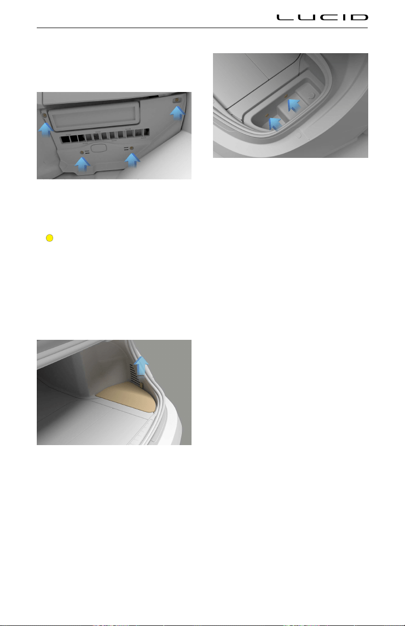
Cabin fuse box
The cabin fuse box is located in the front
passenger’s footwell.
Remove the four star screws securing the
close-out panel in place. Lower the panel to
access the fuse box.
CAUTION: Take care when lowering
the trim panel as the air distribution
outlet for the passenger footwell and
the footwell lamp are secured to the
reverse side of the panel.
Rear fuse box
Remove the right-hand floor panel.
Remove the two push pins securing the under-
floor storage box in place. Remove the storage
box to access the rear fuse box.
Maintenance 164

Front Fuse Box
JC1
JC2
MB1
MB3
MB2
MB5
MB7
MB6
MB4
MB16
MB18
TOOL
MB21
JC7
JC6
MB20
JC3
MB28
JC8
MB27
MB22
MB9
MB13
MB8
MB12
MB11
MB10
MB15
MB14
JC5
JC4
MB29
MB30
MB23
MB25
MB24
MB26
MB19
MB17
Micro2 Blade Fuse Rating (A) Usage
MB1 5 Short Range Radar Enable
MB2 5 Cabin Coolant Valve
MB3 5 Lidar
MB4 5 Powertrain Coolant Valve
MB5 20 Cabin Coolant Pump
MB6 20 Battery Coolant Pump
MB7 20 Front Powertrain Coolant Pump
MB8 10 Vehicle Control Unit
MB9 5 AC Compressor
MB10 10 Right Rear Gateway
MB11 20 Right Headlight
MB12 20 Rear Powertrain Coolant Pump
MB13 20 Not Applicable
MB14 7.5 Quiescent Power Input
MB15 20 Front Motor Control Unit
MB16 15 Body Control Module
MB17 5 Vehicle Control Unit Quiescent Power
Maintenance 165

Micro2 Blade Fuse Rating (A) Usage
MB18 5 Body Control Module Quiescent Power
MB19 5 Onboard Charger
MB20 5 HVAC Heater
MB21 15 Body Control Module
MB22 5 Telematics Control Unit Quiescent Power
MB23 5 Battery Pack Controller
MB24 5 Pedestrian Warning System
MB25 5 Radiator Grill Shutter
MB26 5 Homelink
MB27 10 Left Rear Gateway
MB28 5 Battery Chiller Expansion Valve
MB29 5 Not Applicable
MB30 20 Left Headlight
Low-Profile JCase Fuse Rating (A) Usage
JC1 40
Intelligent Booster Unit
(IBU)
JC2 20 Vehicle Control Unit
JC3 30 Left Front Window Motor
JC4 20 Frunk Actuators
JC5 30 Right Front Window Motor
JC6 40 HVAC Blower Left
JC7 40 HVAC Blower Right
JC8 60
Vehicle Dynamics Controller (VDC)/Electronic Stability Program
(ESP)
Maintenance 166

Cabin Fuse Box
MB22
JC12
JC11
JC10
JC9
TOOL
MB23
MB14
MB6
JC8
JC7
JC6
JC5
JC4
JC3
JC2
JC
1
MB24
MB29
MB28
MB27
MB26
MB25
MB21
MB20
MB19
MB18
MB17
MB16
MB15
MB1
MB13
MB12
MB11
MB10
MB9
MB8
MB7
MB4
MB5
MB3
MB2
Micro2 Blade Fuse Rating (A) Usage
MB1 10 Not Applicable
MB2 15 Left Front Door Control Module and Door Handle
MB3 5 Driver Monitoring System
MB4 5 Restraint Control Module (Airbag Module)
MB5 5 Passenger Seat Controller
MB6 5 Rear Solar Sensor
MB7 5 Instrument Cluster Controller and Center Console Controller
MB8 5 Not Applicable
MB9 5 Rear HVAC Control Display
MB10 20 Trunk 12V Outlet
MB11 15 Left and Center Cluster Display
MB12 5 Interior Radar and Intrusion Detection Sensor
MB13 15 Left Rear Door Control Module and Door Handle
MB14 10 Driver Seat Massage Motors
MB15 10 Passenger Seat Massage Motors
MB16 15 Right Front Door Control Module and Door Handle
MB17 5 Tire Pressure Monitoring System (TPMS)
MB18 15 Right Cluster Display and Center Information Display
MB19 20 Steering Column Adjuster
Maintenance 167

Micro2 Blade Fuse Rating (A) Usage
MB20 5 Occupant Classiication System
MB21 5 Rear View Mirror
MB22 5 Driver Seat Controller
MB23 5 Steering Column Control Module
MB24 5 Parking Control Unit
MB25 5 Wireless Charging Pad
MB26 5 Access Control Module
MB27 15 HVAC Controller
MB28 15 Right Rear Door Control Module and Door Handle
MB29 10 USB Modules Front and Rear
Low-Profile JCase Fuse Rating (A) Usage
JC1 30 Not Applicable
JC2 30 Left Rear Door Window Motor
JC3 40 Left Cooling Fan
JC4 25 Passenger Seat Heater and Ventilation
JC5 30 Not Applicable
JC6 30 Passanger Seat Adjust
JC7 30 Right Rear Door Window Motor
JC8 40 Right Cooling Fan
JC9 25 Driver Seat Heater and Ventilation
JC10 30 Not Applicable
JC11 30 Not Applicable
JC12 30 Driver Seat Adjust
Maintenance 168

Rear Fuse Box
MB11
MB10
JC4
JC5
JC6
JC3
MB8
TOOL
MB9
MB7
MB6
MB5
MB4
MB2
MB1
JC2
JC1
MB3
Micro2 Blade Fuse Rating (A) Usage
MB1 10 Not Applicable
MB2 10 Not Applicable
MB3 10 Not Applicable
MB4 10 Not Applicable
MB5 10 Telematics Control Unit
MB6 10 Not Applicable
MB7 10 Not Applicable
MB8 20 Suspension Control Unit
MB9 5 Not Applicable
MB10 5 Not Applicable
MB11 20 Rear Motor Control Unit
Low-Profile JCase Fuse Rating (A) Usage
JC1 30 Not Applicable
JC2 40 Not Applicable
JC3 30 Not Applicable
JC4 30 Decklid Actuators
JC5 25 Not Applicable
Maintenance 169

Low-Profile JCase Fuse Rating (A) Usage
JC6 25 Not Applicable
Maintenance 170

Parts and Accessories
Parts, Accessories, and Modifications
WARNING: Lucid does not recommend
installing non-approved parts and
accessories or performing non-
approved vehicle modifications. Doing
so can negatively affect your vehicle’s
performance and the safety of its
occupants. The warranty will not
cover any damage caused by using
or installing non-approved parts
or accessories, or performing non-
approved modifications.
WARNING: Lucid is not responsible for
death, injury, or damage that occurs
as the result of using or installing
non-approved parts or accessories, or
making non-approved modifications.
Genuine Lucid parts and accessories are
the best choice for your vehicle. Lucid has
rigorously tested all of their parts to ensure
they meet the highest quality, safety, and
performance standards.
Genuine parts and accessories can be
purchased and professionally installed at
a Lucid Service Center, where qualified
technicians can offer you the best advice on
repairs, accessories, and modifications.
Because they cannot assess products from
other manufacturers or distributors, Lucid is
not responsible for any issues related to using
non-Lucid parts or accessories on your vehicle.
Note: If you have a disability which may require
modification to the vehicle, please contact
Lucid before any modifications are made. See
Contacting Lucid Motors on page 210.
Body Repairs
If your vehicle is damaged due to a collision,
please contact a Lucid Service Center for
referral to an approved body repair shop. This
will ensure repairs are performed by a qualified
technician using proper equipment and genuine
Lucid parts. Poorly-performed collision repairs
can compromise the performance and safety
of the vehicle, and the resale value can be
diminished.
Some repair shops may suest using other
parts instead of those made by Lucid, including
salvaged or refurbished parts, or aftermarket
parts made by other companies. While these
suestions may cut repair costs, they are
not recommended and are not covered by the
warranty.
- Salvaged parts may maintain the vehicle’s
designed appearance, but their unknown
history means they may have been
damaged during the previous vehicle’s life
or while in storage.
- Refurbished or aftermarket parts have not
undergone extensive testing by Lucid to
assure their safety or reliability.
Any vehicle failure related to salvaged,
refurbished, or aftermarket parts is not covered
by the warranty.
Maintenance 171
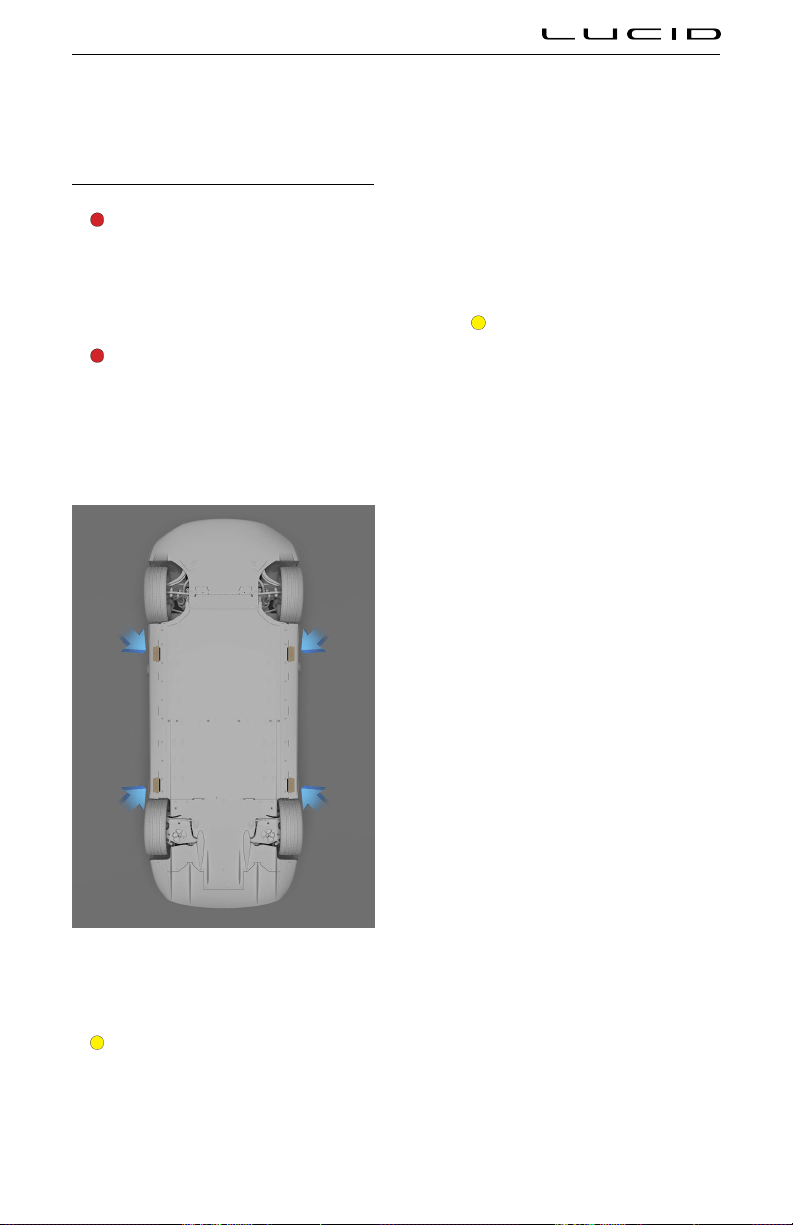
Vehicle Lifting Points
Lifting the Vehicle
WARNING: Never raise the vehicle
when the charging cable is connected,
even if charging is not in progress.
Always disconnect the charging cable
before raising the vehicle. See
Disconnecting the Charging Cable on
page 145.
WARNING: Do not work on an
incorrectly-supported vehicle. Doing
so can cause serious damage, bodily
injury, or death.
The lifting points for the vehicle are located at
the positions shown below.
Ensure that any non-Lucid repair facility
servicing your vehicle is aware of these lifting
points when raising your vehicle on a lift.
CAUTION: These are the only approved
lifting points for your vehicle. Lifting the
vehicle at any other points may cause
irreparable damage to the vehicle.
Steps for lifting the vehicle
1. Position the vehicle centrally between the
lift posts.
2. Position the lift arm pads under the
designated body lifting points at the
locations shown.
CAUTION: DO NOT position the
lift arm pads under the vehicle
battery or side rails.
3. Adjust the height and position of the lift
arm pads to ensure that they are correctly
located.
4. With assistance, raise the lift to the
desired height, ensuring the lift arm pads
remain in their correct positions.
5. Engage any lift safety locks. Follow the lift
manufacturer's instructions.
Maintenance 172
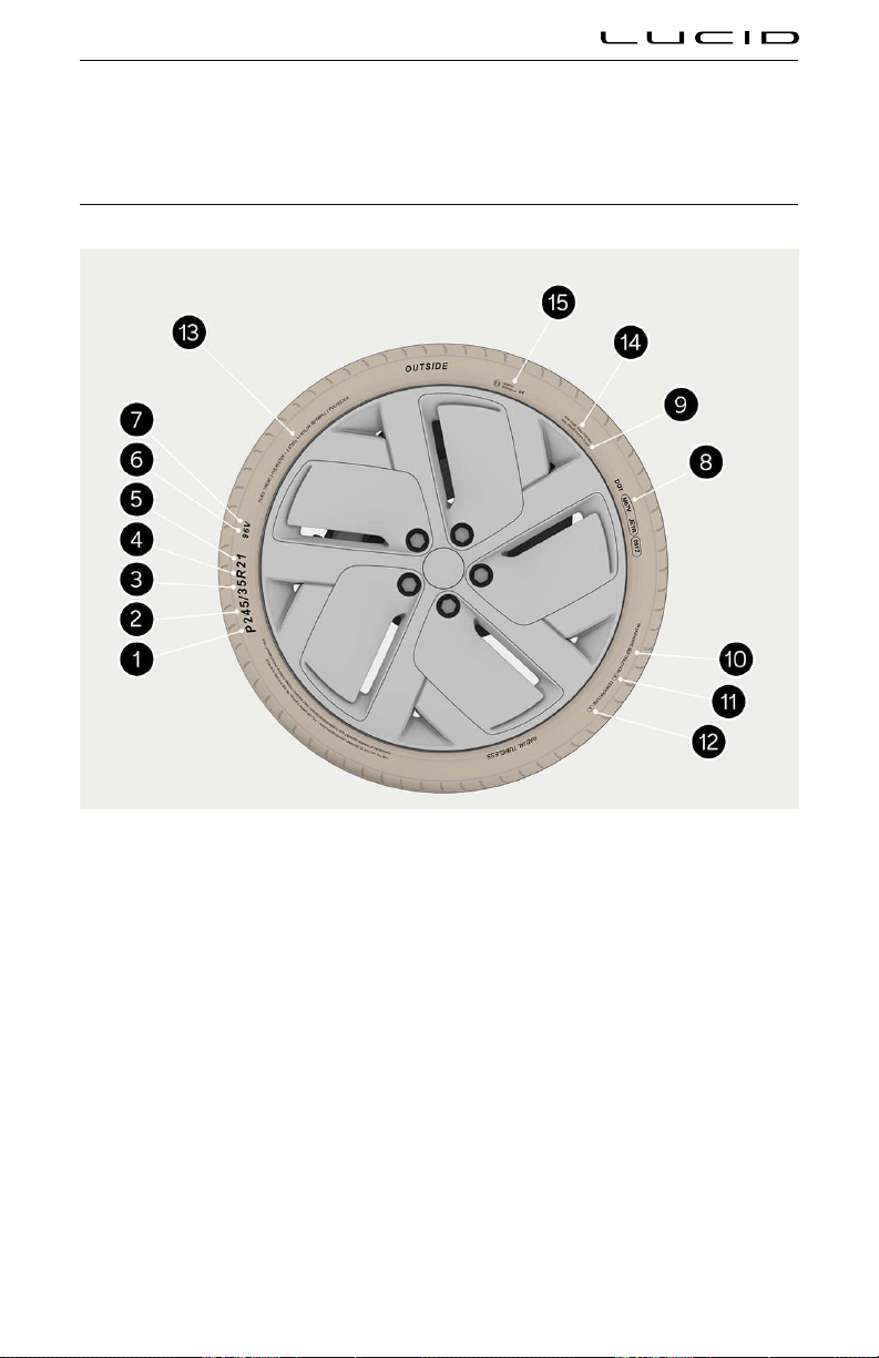
Tire Information
Understanding Tire Markings
Federal law requires tire manufacturers to place standardized information on the sidewall of all tires.
This information identifies and describes the fundamental characteristics of the tire and also provides
the tire identification number (TIN) for safety standard certification and in case of a recall.
1. Tire category
P indicates that the tire is for passenger vehicles. HL indicates that the tire is a high-load rated tire.
Note: May not be shown on some tires.
2. Tire width
This three-digit number gives the width in millimeters of the tire from sidewall edge to sidewall edge.
So, if a tire is marked P245/35R21, the tire width is 245 mm.
3. Aspect ratio
This two-digit number, also known as the profile, gives the sidewall height as a percentage of the tire
width. So, if the tire width is 245 mm, and the aspect ratio is 35, the sidewall height will be 85.75 mm.
Tire & Wheels 173

4. Tire construction
R indicates that the tire is of Radial ply construction. So, if a tire is marked P245/35R21, R is the Radial
ply construction.
5. Wheel diameter
This two-digit number is the diameter of the wheel rim in inches. So, if a tire is marked P245/35R21,
the wheel diameter is 21 inches.
6. Load index
This two- or three-digit number is the tire's load index. It is a measurement of how much weight each
tire can support. This number is not always shown.
7. Speed rating
The speed rating, when stated, denotes the maximum speed at which the tire should be used for
extended periods. The ratings range from 99 mph (160 km/h) to 186 mph (300 km/h). These ratings are
listed in the following table.
Rating Speed (mph) Speed (km/h)
Q 99 160
106 170
S 112 180
T 118 190
U 124 200
H 130 210
V 149 240
W 168 270
Y 186 300
8. U.S DOT Tire Identification Number (TIN)
Regulations require that the TIN begins with the letters “DOT” and is followed by two numbers or
letters that indicate where it was manufactured. The last four numbers represent the week and year
the tire was built. For example, the number 1706 means the 17th week of 2006. The other numbers
are marketing codes used at the manufacturer's discretion. This information can be used to contact
consumers if a tire defect requires a recall.
9. Maximum permissible inflation pressure
Maximum permissible inflation pressure means the maximum cold inflation pressure to which a tire
may be inflated. It is okay for the tire pressure to exceed this value when it is warmed up, but it must
be at or below this pressure when the tire is cold.
10. Treadwear grade
This number indicates the tire's wear rate. See
Uniform Tire Quality Grading.
11. Traction grade
This letter indicates a tire's ability to stop on wet pavement. See Uniform Tire Quality Grading.
Tire & Wheels 174

12. Temperature grade
This letter indicates a tire's heat resistance grading. See Uniform Tire Quality Grading.
13. Tire composition and materials
The number of plies in both the tread area, and the sidewall area, indicates how many layers of rubber
coated material make up the structure of the tire. Information is also provided on the type of materials
used.
14. Maximum tire load
This is the maximum load that can be carried by the tire.
15. International tire approval marks
See International Tire Approval Marks.
Tire & Wheels 175
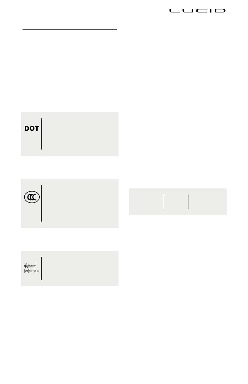
International Tire Approval Marks
Before any tires can be sold in most countries,
tire manufacturers must test and certify that all
applicable safety and performance standards
are met. This can include, sidewall branding,
durability, physical dimensions, high-speed
endurance, road noise, and wet traction.
Many tires are sold globally, so tires may be
branded with multiple approval codes from
various countries.
United States
United States Department of
Transportation (DOT)
See 8. U.S DOT tire identiication
number (TIN).
China
China Compulsory Certiication (CCC)
Mark
China Compulsory Certiication mark
for products being exported to or sold
in the Peoples Republic of China.
Europe
United Nations Economic Commission
of Europe (U.N.E.C.E.)
The symbol identifying the United Nations
Economic Commission for Europe (U.N.E.C.E.,
sometimes referred to as E.C.E.) is found on
a tire's sidewall which certifies that the tire
manufacturer meets all regulations, including
the load index and speed symbol appearing in
its service description.
The letter “E” or “e” and number code (in a
circle or rectangle) identifies the country where
the tire was originally registered, followed
by two digits (the Regulation Series) where
the tire was approved (such as “02” for
E.C.E. Regulation 30 governing passenger tires)
followed by digits representing the E.C.E. mark,
type-approval numbers.
Tested tires meeting the “pass-by” noise and
wet traction limits may have another E.C.E.
branding followed by an “-s” and “w” (for
sound and wet traction, respectively). One or
two E.C.E. symbols may appear on the tire's
sidewall.
Uniform Tire Quality Grading
The following information relates to the tire
grading system developed by the National
Highway Traffic Safety Administration (NHTSA),
which will grade tires by tread wear, traction
and temperature performance.
Note: Tires that have deep tread, and
winter tires, are exempt from these marking
requirements.
Quality grades, where applicable, can be found
on the tire sidewall between the tread shoulder
and maximum section width. For example:
TREADWEAR
180
TACTION
AA
TEMPEATURE
A
In addition to the marking requirements,
passenger car tires must conform to Federal
Safety Requirements.
Treadwear
The treadwear grade is a comparative rating
based on the wear rate of the tire when tested
under controlled conditions on a specified
government test course.
For example, a tire graded 150 would wear
one and a half times as well on a government
test course as a tire graded 100. The relative
performance of tires depends on the actual
conditions of their use, however, and may
depart significantly from the norm due to
variations in driving habits, service practices,
and differences in both road characteristics
and climate.
Traction
Note: The traction grade assigned to this
tire is based on straight-ahead braking tests,
Tire & Wheels 176

and does not include acceleration, cornering,
hydroplaning, or peak traction characteristics.
The traction grades, from highest to lowest,
are: AA, A, B, and C. These grades represent
a tire’s ability to stop on a wet pavement
as measured under controlled conditions on
specified government test surfaces of asphalt
and concrete. A tire marked C may have poor
traction performance.
Temperature
WARNING: The temperature grade for
this tire is established for a tire that
is properly inflated and not overloaded.
Excessive speed, under-inflation, or
excessive loading, either separately or
in combination, can cause heat build-
up and possible tire failure.
The temperature grades are A (the highest), B,
and C, representing the tire's resistance to the
generation of heat and its ability to dissipate
heat when tested under controlled conditions
on a specified indoor laboratory test wheel.
Sustained high temperature can cause the
material of the tire to degenerate and reduce
tire life, and excessive temperature can lead to
sudden tire failure.
The grade C corresponds to a level of
performance that all passenger car tires must
meet under the Federal Motor Safety Standard
No. 109.
Grades B and A represent higher levels of
performance on the laboratory test wheel than
the minimum required by law.
Tire and Loading Information Label
Open the left front door to locate the tire
information label on the driver's side center
pillar.
The label contains the following information:
- The maximum vehicle capacity weight in
kilograms (kg) and pounds (lb).
- Maximum number of occupant seating
positions in the vehicle.
- The size of the tires originally fitted to the
vehicle.
- The cold inflation pressures for the
original specification of front and rear
tires.
The stated tire pressures provide the optimum
vehicle ride and handling characteristics for all
normal operating conditions.
Note: Do not change this label, even if you use
different tires in the future.
Tire & Wheels 177

Tire Care and Maintenance
Inspecting and Maintaining Tires
WARNING: The tires should be regularly
checked for wear and to make sure that
there are no cuts, bulges, or exposure of
the ply/cord structure. Do not drive with
tires that are worn, damaged, or inflated
to the incorrect pressure. Driving under
any of these conditions could lead to
collision due to tire failure and/or loss
of control and result in serious injury or
death to the occupants or others.
Always consider tire conditions when driving,
and regularly inspect the tread and sidewalls
for any sign of distortion (bulges), cuts, or wear.
Good driving practice will improve the
mileage you obtain from your tires and avoid
unnecessary damage.
- Always ensure that the tire pressures are
correctly adjusted.
- Always observe the posted speed limits
and advisory speeds.
- Avoid pulling away quickly or hard
acceleration.
- Avoid making fast turns or braking
sharply.
- Avoid potholes and objects on the road.
- Do not run over curbs or hit the tire
against the curb when parking.
CAUTION: Avoid contaminating tires
with vehicle fluids that can cause
damage.
Tire wear
WARNING: The tire wear indicators
show the minimum tread depth
recommended by the tire manufacturer.
Tires that have worn to this point
will have reduced grip and poor water
displacement characteristics.
Tires fitted as original equipment have tread
wear indicators molded into the tread pattern.
When the tread has been worn down to
approximately 2/32 inch (1.6 mm), the indicators
become flush with the surface of the tread
pattern, producing the effect of a continuous
band of rubber across the width of the tire.
A tire must be replaced as soon as an indicator
band becomes flush to the tread, indicating the
tread has reached the minimum permitted by
legislation.
Note: Your Lucid Service Center will evaluate
tire wear when servicing your vehicle.
Wheel alignment and tire balance
Unbalanced wheels (sometimes noticeable as
steering wheel vibration) may affect vehicle
handling and tire life. Even with regular use,
wheels can get out of balance. Therefore, you
should balance your wheels as required.
Note: If tire wear is uneven (on one side of the
tire only) or becomes abnormally excessive, you
should check the wheel alignment.
Wheel and tire rotation
WARNING: Your vehicle may be fitted
with different size tires on the front and
rear wheels. The front and rear wheels
may also have different offsets. Do not
move wheels between the front and
rear axles as this will severely affect
vehicle handling.
Lucid does not recommend moving the wheels
between the front and rear axles, or from side
to side on the same axle pair.
Tire & Wheels 178

Punctured tires
WARNING: Do not drive the vehicle with
a punctured tire. Even if the punctured
tire has not deflated, it is unsafe to use
as the tire may deflate suddenly at any
time.
Your vehicle is fitted with tubeless tires, which
may not leak when penetrated, provided the
object remains in the tire.
If, however, you feel a sudden vibration or ride
disturbance while driving, or you suspect your
tire or vehicle has been damaged, immediately
reduce your speed. Drive slowly while avoiding
heavy braking or sharp steering, and when safe
to do so, stop the vehicle.
Inspect the tires for damage. If a tire is under-
inflated and does not appear to have any
damage to the sidewall, try to repair it using the
tire repair kit. See Tire Repair Kit. If you cannot
detect the cause or the tire is too heavily
damaged, have the vehicle recovered to a tire
repair center, or a Lucid Service Center to have
the vehicle inspected.
A puncture will eventually cause the tire to lose
pressure, which is why frequent checking of tire
pressures is important. Punctured or damaged
tires must be permanently repaired or replaced
as soon as possible.
Age degradation
Tires degrade over time due to the effects
of ultraviolet light, extreme temperatures, high
loads, and environmental conditions. It is
recommended that tires are replaced every
six years, but may require replacement more
frequently.
Maintaining Tire Pressures
WARNING: Use a gauge to check tire
pressures when COLD. Under-inflation
is the most common cause of tire
failures and may result in severe tire
cracking, tread separation, or “blowout,”
with an unexpected loss of vehicle
control and increased risk of injury.
Each tire should be checked monthly and
inflated to the pressure recommended on the
vehicle placard or tire inflation pressure label.
(If your vehicle has tires of a different size than
the size indicated on the vehicle placard or tire
inflation pressure label, you should determine
the proper tire inflation pressure for those
tires).
Driving on a significantly under-inflated tire
causes the tire to overheat and can lead to
tire failure. Under-inflation also reduces battery
range and tire tread life, and may affect the
vehicle’s handling and stopping ability.
As an added safety feature, your
vehicle has been equipped with a Tire
Pressure Monitoring System (TPMS)
that illuminates a low tire pressure
indicator when one or more of your tires is
significantly under-inflated. When the low tire
pressure indicator illuminates, you should stop
and check your tires as soon as possible, and
inflate them to the proper pressure. See Tire
Pressure Monitoring System (TPMS) on page
183.
WARNING: TPMS is not a substitute for
proper tire maintenance. As the driver,
it is your responsibility to maintain
correct tire pressure, even if under-
inflation has not reached the level to
trier illumination of the TPMS low tire
pressure indicator.
Checking tire pressure
CAUTION: Perform pressure checks
when the tires are COLD. A hot tire at
or below recommended cold inflation
pressure is dangerously under-inflated.
CAUTION: If the vehicle has been
parked in strong sunlight or used in
high ambient temperatures, do not
reduce the tire pressures. Move the
vehicle into the shade and allow the
tires to cool before checking.
WARNING: Do not exceed the maximum
pressure stated on the sidewall of the
tire. Over-inflation could cause the tire
to fail suddenly.
Note: The COLD Tire pressure is defined as the
air pressure in a tire that has been standing in
excess of three hours, or driven for less than
one mile.
To view current tire pressures on the Pilot
Panel. Select
> Vehicle > Tire Pressure.
Note: Tire pressure is shown once the vehicle is
driven over 13 miles per hour.
If it is necessary to check the tires when they
are warm, you should expect the pressures to
Tire & Wheels 179

have increased. Do not reduce the pressure
of warm tires in an attempt to match the
recommended cold tire pressures.
To view the recommended COLD tire pressures
for your vehicle, select the RECOMMENDED
tab. Always inflate your tires to the pressures
recommended by Lucid, even if it is
different from the maximum inflation pressure
information found on the tire itself.
Adjusting tire pressure
The recommended COLD tire pressures are
also shown on the Tire and Loading Information
Label located on the driver's side door jamb.
Recommended Tire Inflaton Pressure depends
on the type of tires mounted on the vehicle at
the factory. The label, located on the left door
jamb between front and rear doors, provides
the Tire and Loading Information for your
vehicle.
To check and adjust tire pressures:
1. Remove the cap from the valve, then
firmly press the tire gauge onto the valve
and measure the pressure.
2. If required, add air to reach the required
pressure.
3. Check the pressure by removing the tire
gauge and then re-attaching it. Failure to
remove and re-attach the gauge to the
valve could cause the gauge to show an
incorrect reading.
4. If the tire pressure is too high, remove
the gauge and release air from the tire by
pressing on the metal stem in the center
of the valve. Refit the gauge to the valve
and check the pressure.
5. Repeat the process of adding or removing
air as required until the correct tire
pressure is reached.
6. Refit the valve cap.
Tire valves
Keep the valve caps screwed down firmly to
prevent water or dirt from entering the valve.
Check the valves for leaks when checking the
tire pressures.
Flat spots
If the vehicle is stationary for a long period
when the ambient temperature is high, the tires
may form flat spots. When the vehicle is driven,
these flat spots will cause a vibration that will
steadily disappear as the tires warm up and
regain their original shape.
Tire pressures during long-term storage
Inflate tires to the maximum pressure as
indicated on the tire wall to minimize flat spots
during storage.
WARNING: The tire pressures must be
reduced to the correct pressure before
the vehicle is driven.
Replacing Tires and Wheels
WARNING: For your safety, it is
recommended that only wheels
and tires that match the original
specification are used on the vehicle.
Specifications for approved winter tires
are available by contacting your Lucid
Service Center.
WARNING: Operation of the Tire
Pressure Monitoring System (TPMS)
may be affected if the tires are replaced
with a different specification from the
originals.
Wheel rims and tires are matched to suit
the handling characteristics of the vehicle.
Always check that replacement tires comply
with the original specification. If tires other
than those specified are used, ensure that the
load and speed ratings (shown on the tire side
wall) equal or exceed those of the original
specification.
For the specification of the original wheels and
tires installed on the vehicle, refer to
Wheel and
Tire Specifications.
Tire & Wheels 180

Ideally, tires should be replaced as sets of
four. If this is not possible, replace the tires in
pairs (front and rear). When tires are replaced,
the wheels should always be re-balanced and
alignment checked.
Asymmetric tires
WARNING: Vehicle traction and
handling will be seriously impaired if
the tires are incorrectly installed on the
wheels.
Your vehicle is equipped with Asymmetric tires
that have different tread patterns on the outer
and inner edge of the tire. On the outside edge,
the tread pattern exhibits large tread blocks
that are designed to provide dry traction and
handling thanks to a larger contact area with
the road.
On the inside edge, the tread block is smaller to
provide better wet grip. An increased number of
grooves helps disperse water on wet roads and
reduce the risk of aquaplaning. This means the
tire is built to provide great performance in both
wet and dry conditions.
Asymmetric tires must be mounted on the
wheel with the correct sidewall facing outwards
from the vehicle. The sidewall of the tire is
marked with the word OUTSIDE.
When new tires are installed, always make sure
the tires are correctly oriented.
Run-flat tires
CAUTION: The installation of run-flat
tires is not recommended by Lucid as
they may cause issues with the sensors
for the Tire Pressure Monitoring System
(TPMS).
Seasonal Tire Types
Summer tires
Your vehicle may be originally equipped with
high-performance summer tires. Summer tires
are designed for maximum dry and wet road
performance but are not designed to perform
well in winter conditions.
Lucid recommends using winter tires if driving
in cold temperatures or on roads where snow or
ice may be present.
WARNING: Summer tires are not
designed to provide adequate traction
during cold temperatures, on snow,
or ice. Selecting and installing the
appropriate tires for winter conditions
is important to ensure the safety and
optimum performance of your vehicle.
All-season tires
Your vehicle may be originally equipped with
all-season tires. These tires are designed to
provide adequate traction in most conditions
year-round, but may not provide the same level
of traction as winter tires in snowy or icy
conditions. All-season tires can be identified by
ALL SEASON and/or M+S (mud and snow) on
the tire sidewall.
Winter tires
WARNING: Always follow the tire
manufacturer’s instructions. Pay special
attention to the maximum speed you
can drive your vehicle and the correct
tire pressures.
WARNING: The traction provided by
winter tires on dry roads may be less
than your original specification tires.
Use winter tires to increase traction when
driving in sustained temperatures below 50°F
(10°C), or in snowy or icy conditions.
For winter tires, always install a complete set
of four tires at the same time. All winter
tires should be the same diameter, brand,
construction, and tread pattern on all four
wheels.
For recommendations on winter tires, contact
your Lucid Service Center.
Tire & Wheels 181

Driving in Low Temperatures
Tire performance is reduced in low ambient
temperatures, resulting in reduced grip and
increased susceptibility to damage from
impacts. Performance tires can temporarily
harden when cold, causing you to hear
rotational noise for the first few miles
(kilometers) until the tires warm up.
Tire Traction Devices
Tire chains
CAUTION: The use of tire chains
is not approved or recommended by
Lucid. Using tire chains may damage
your vehicle’s suspension, body, wheels,
and/or brake lines. Damage caused by
using tire chains will not be covered by
the New Vehicle Limited Warranty.
Tire socks
When the tires do not provide sufficient
traction, tire socks may be fitted and used at
speeds of up to 25 mph (40 kph) in snowy
conditions.
Note: Winter tires usually offer more traction
than tire socks.
Note: Although approved by Lucid, the use of
tire socks may still be prohibited according to
location. Check the local laws before installing
tire socks.
For recommendations on tire socks, contact
your Lucid Service Center.
Tire & Wheels 182
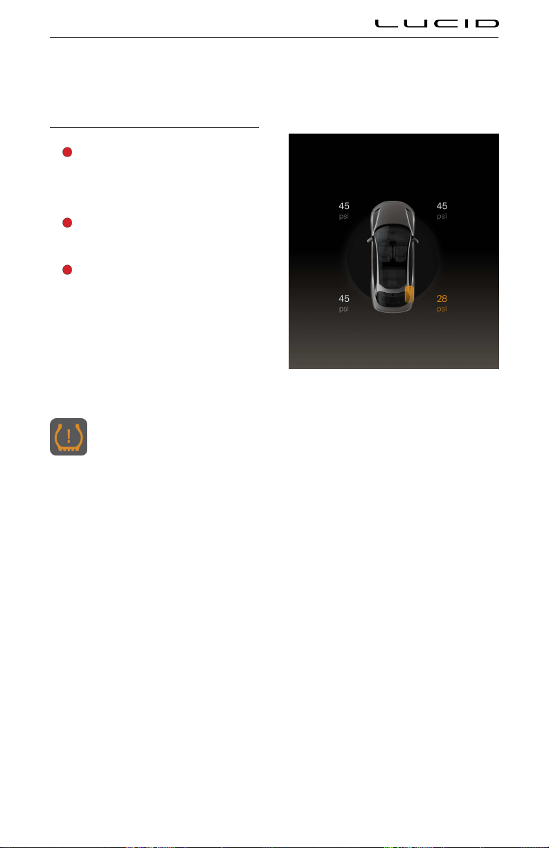
Tire Pressure Monitoring System
Tire Pressure Monitoring System (TPMS)
WARNING: The TPMS is not a
substitute for manually checking tire
pressures. The TPMS only provides a
tire pressure warning and does not re-
inflate the tires.
WARNING: The TPMS cannot register
damage to a tire. Regularly check the
condition of your tires.
WARNING: Using liquid or aerosol tire
sealants may cause a malfunction of
tire pressure sensors.
The TPMS monitors the pressure of the
tires using sensors located in each wheel. In-
vehicle sensors receive TMPS data using Radio
Frequency (RF) signals.
Note: Installing accessories that are not
approved by Lucid may interfere with the TPMS
system.
Tire pressure warnings are displayed
on the Instrument Cluster using an
amber warning indicator. A warning
chime will sound, and a warning
message will display to alert you to a problem.
The tire pressure warning indicator will
illuminate if a tire is under-inflated.
If the tire pressure warning indicator
illuminates, stop and check your tires as soon
as possible and inflate them to the correct
pressure. If the tire pressure warning occurs
frequently, the cause must be determined and
rectified.
Tire pressure information display
If low tire pressure is detected, the Instrument
Cluster will provide an overview of the tire
pressures on the vehicle. The wheel with the
low pressure will be displayed in amber.
TPMS malfunction
Your vehicle is equipped with a TPMS
malfunction indicator to indicate when the
system is not operating properly.
The TPMS malfunction indicator is combined
with the low tire pressure indicator. When the
system detects a malfunction, the indicator will
flash for approximately one minute and then
remain continuously illuminated. This sequence
will continue upon subsequent vehicle start-
ups as long as the malfunction exists.
When the malfunction indicator is illuminated,
the system may not be able to detect or
signal low tire pressure as intended. TPMS
malfunctions may occur for a variety of reasons,
including the installation of replacement or
alternate tires or wheels on the vehicle that
prevents the TPMS from functioning properly.
Always check the TPMS malfunction indicator
after replacing one or more tires or wheels on
your vehicle to ensure that the replacement or
alternate tires and wheels allow the TPMS to
function properly.
Note: If a tire has been repaired using tire
sealant and low tire pressure is detected, it's
possible that the TPMS has been damaged.
Contact a Lucid Service Center to have the
issue rectified as soon as possible.
Tire & Wheels 183

Tire pressure correction
The tire pressure indicator light does not
automatically turn off when the tire pressure is
adjusted for all four tires.
After the tires are inflated to the correct
pressures, drive your vehicle over 18 mph
(30 km/h) for more than 10 minutes to activate
the Tire Pressure Monitoring System (TPMS)
and turn off the low tire pressure indicator light.
Tire changing
Always have your tires serviced or changed by a
qualified technician.
Care must be taken to avoid contact between
the bead of the tire and the sensor during
removal and refitting of the tire, otherwise
the sensor may become damaged and/or
inoperable.
Replacing a tire pressure sensor
If you experience frequent low tire pressure
warnings and the tire pressures are correct,
contact Lucid Service Center to determine if
a tire pressure sensor requires replacement.
Note: If a non-Lucid Service Center has
replaced a tire pressure sensor, it may not work
until it has been programmed to the vehicle by
Lucid.
Tire & Wheels 184
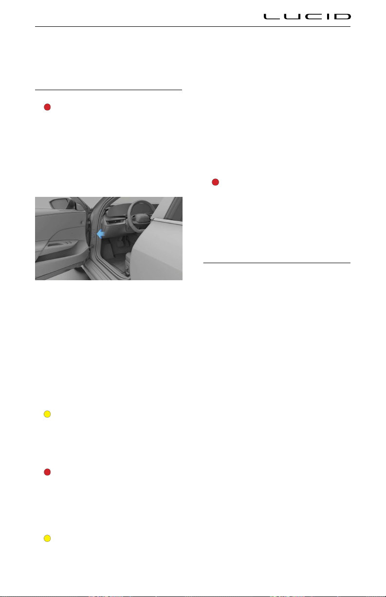
Vehicle Loading
Loading the Vehicle
WARNING: Overloading the vehicle has
an adverse effect on braking and
handling characteristics, which can
compromise your safety or damage the
vehicle.
It is important to understand the maximum
weight rating for your vehicle and how much
weight your vehicle can safely carry.
See the vehicle certification label located
on the driver side front door jamb, by the
front wheel, for the maximum load for your
vehicle.vehicle’s Gross Vehicle Weight Rating
(GVWR)
Note: Gross Vehicle Weight Rating (GVWR) is
also known as the total allowable mass of the
vehicle. This weight includes the vehicle's curb
weight, all occupants, cargo, and any additional
equipment installed on the vehicle since it was
manufactured.
CAUTION: To prevent severe damage to
the vehicle, never load the vehicle to be
heavier than the GVWR.
Carrying items
WARNING: The frunk and trunk are
the preferred places to carry objects.
In an accident, during hard braking, or
sudden maneuvers, loose items carried
in the vehicle’s cabin area can be
thrown around and cause injury to
occupants.
CAUTION: Heavy loads should be
evenly distributed throughout the
vehicle so as not to exceed the Gross
Axle Weight Ratings (GAWR) shown
on the vehicle certification label. Refer
to the tire information and loading
label in the next section to determine
the recommended maximum allowable
weight that can be added to the vehicle
to safely operate it and not damage the
vehicle.
Towing a trailer
WARNING: Do not tow a trailer with
your vehicle. The vehicle has not been
designed to have a trailer hitch fitted to
it. The installation of a trailer hitch may
cause serious damage to the vehicle,
which could result in an accident or
serious injury.
Steps for Determining Correct Load Limit
1. Locate the statement “The combined
weight of occupants and cargo should
never exceed xx kg or xx lb” on your
vehicle’s placard (Tire information and
loading label).
2. Determine the combined weight of the
driver and passengers that will be riding
in your vehicle.
3. Subtract the combined weight of the
driver and passengers from the never
exceed weight identified in step 1.
4. The resulting figure equals the available
amount of cargo and luage load
capacity. For example, if the total amount
equals 950 lb, and there will be five 150
lb passengers in the vehicle, the amount
of available cargo and luage capacity is
200 lb (950-750 (5x150) = 200 lb).
5. Determine the combined weight of
luage and cargo being loaded on the
vehicle. That weight may not safely
exceed the available cargo and luage
load capacity calculated in Step
4.
Example load limit calculations
The number and weight of passengers will
affect the weight of available cargo and luage
load capacity.
Tire & Wheels 185

The following are typical examples of
calculated load limits.
Description Total
Vehicle Capacity Weight = 950 lb
Subtract Occupant Weight (2 x 150 lb) = 300 lb
Available Cargo or Luggage Weight = 650 lb
Description Total
Vehicle Capacity Weight = 950 lb
Subtract Occupant Weight (4 x 150 lb) = 600 lb
Available Cargo or Luggage Weight = 350 lb
Note: Calculations for the available cargo and
luage capacity assume that the passengers
weigh 150 lb. If the passengers weigh more
than this, the available cargo and luage load
capacity will decrease.
Tire & Wheels 186

Vehicle Identiication
Vehicle Identification Number
You may be asked to provide the
Vehicle Identification Number (VIN) when
communicating with Lucid. You can find the
VIN in the following locations:
- Top of dashboard - the VIN is visible
through the lowest part of the left-hand
side of the windshield.
- On the Pilot Panel, select > About
Vehicle to view the VIN.
Note: The VIN is also shown on the vehicle
certification label and tire information label.
Vehicle Certification Label
The vehicle certification label is located on the
left A‑pillar.
The vehicle certification label states the
following important information:
- Manufacturer of the vehicle
- Date the vehicle was manufactured
(MM/YY)
- Gross Vehicle Weight Rating (GVWR)
Note: GVWR is the maximum allowable
weight of the fully-loaded vehicle.
This includes all options, equipment,
passengers, and cargo.
- Gross Axle Weight Rating (GAWR)
Note: GAWR is the maximum allowable
weight that a single axle (front or rear) can
carry.
- Vehicle Identification Number (VIN)
WARNING: Do not exceed the GVWR
or the GAWR specified on the vehicle
certification label.
WARNING: Exceeding the certification
label vehicle weight limits can adversely
affect the performance and handling
of your vehicle. Overloading may
also cause permanent damage to
components, which could result in a
loss of control of your vehicle, serious
personal injury, or death.
WARNING: Do not use replacement
tires with lower load-carrying capacities
than the original tires, because they
may lower your vehicle's GVWR and
GAWR limitations. Replacement tires
with a higher limit than the original tires
do not increase the GVWR and GAWR
limitations.
Technical Data 187

Vehicle Dimensions and Weights
Exterior Dimensions
Identifier Description Dimensions (19" / 21")
A Overall length 4975 mm
B Overall width - mirrors included 2196 mm
C Overall height 1408 / 1414 mm
D Overall height - deck lid open 1737 / 1747 mm
E Overall height - hood open 1839 / 1842 mm
F Wheel base 2960 mm
G Front overhang 941 mm
H Rear overhang 1075 mm
I Approach angle 11/ 11°
J Departure angle 13 / 14°
K Track - front
Track - rear
1663 / 1669 mm
1689 / 1666 mm
L Ground clearance 126 / 136 mm
Technical Data 188

Vehicle Weights
Curb Weight* (19"/ 21") 2360 kg / 2375 kg
Gross Vehicle Weight Rating (GVWR) 2850 kg
Gross Axle Weight Rating (GAWR) - Front 1430 kg
Gross Axle Weight Rating (GAWR) - Rear 1450 kg
Trailer towing Not permissible
*Curb Weight = Weight of vehicle with correct fluid levels, no occupants, and no cargo
Technical Data 189

Wheels and Tires
Wheel and Tire Specifications
Wheel Type Position Size
Standard production wheels
19” - Aero Range
Front 19x8”
Rear 19x8”
21” - Aero DREAM
Front 21x8.5”
Rear 21x9.5”
Lug nut torque 150 Nm
Lug nut socket size 21 mm
Note: For details on where to lift your vehicle, see Lifting the Vehicle on page 172 .
Tire Type Position Size Load Index / Speed Rating
Standard production-installed tires
19” - Pirelli PZero - All Season All 245/45R19 XL / 102Y
21” - Pirelli PZero - Summer
Front 245/35R21 HLC / 99Y
Rear 265/35R21 HLC / 103Y
Technical Data 190

Tire Pressures
Recommended COLD inflation pressures
Tire pressures may vary depending on the type
of tires itted to your vehicle. Refer to the
tire pressures printed on the Tire and Loading
Information label. This label is located on the left
door pillar and is visible when the front door is
open. See Maintaining Tire Pressure.
Technical Data 191

Vehicle Sub-Systems
Steering
Type Rack and pinion with electronic power steering and speed sensitive assist.
Number of turns lock to lock 2.3 turns
Turning circle (curb to curb) 11.9 m
Technical Data 192

Brakes
Type 4-wheel anti-lock braking system (ABS)with Electronic Brake Force
Distribution,Integrated Electronic Stability Control andelectronic accelerator
pedal-actuatedregenerative braking system.
Calipers Front: six-piston ixed
Rear: four-piston ixed
Rotors Ventilated front and rear rotors.
Front diameter: 380 mm
Rear diameter: 375 mm
Front rotor thickness New: 38 mm
Service limit: 36 mm
Rear rotor thickness New: 30 mm
Service limit: 28 mm
Front brake pad
thickness
New:11 mm
Service limit: 2 mm
Rear brake pad thickness New: 9 mm
Service limit: 2 mm
Parking brake Integrated electronically actuated motor-on-caliper
Technical Data 193

Front Suspension
Type Independent 5-link with stabilizer bar
Alignment CAMBE CASTER (for inspection, not adjustable) TOE
optimum -0.57° 7.3° 0.146°
tolerance +0.25°
- 0.25°
+0.5°
- 0.5°
+0.05°
- 0.05°
Technical Data 194

Rear Suspension
Type Independent integral link with stabilizer bar
Alignment CAMBER (for inspection, not adjustable) TOE
optimum -1.27° 0.110°
tolerance
+0.5°
- 0.5°
+0.05°
- 0.05°
Technical Data 195

Motors
Front Permanent Magnet AC Motor
Rear Permanent Magnet AC Motor
Transmission
Drive Ratio 7.06:1 single speed
12V Batteries
Type Deep Cycle
Quantity 2
Rating 18 Ah
Voltage and polarity 12V Negative (-) ground
High-Voltage Battery
Type Lithium ion (Li-ion)
Cooling Liquid-cooled
Technical Data 196

Roadside Assistance
Contacting Roadside Assistance
Lucid is committed to providing excellent
service. Our Roadside Assistance Program is
available 24 hours a day, 365 days a year. For
assistance call:
+1 888-995-8243 (888-99-LUCID)
Advise the representative of:
- Vehicle identification number (VIN)
- Vehicle description
- License plate number
- Problem with the vehicle
- Your location
Lucid ensures appropriate transportation of its
vehicles under the
Lucid Roadside Assistance
Program. However, it is your responsibility
to provide the vehicle transporter with
instructions on how to transport the vehicle.
See Transporting the Vehicle.
Services Covered
The following are covered at no charge for four
years or 50,000 miles, whichever comes first:
- Emergency Towing/Transport Service for
warranty repairs to the nearest authorized
Lucid Service Center
- Roadside service
- Flat Tire
- 12v Battery
Within the first year of ownership, Lucid
will also provide towing and transport to an
authorized Collison Repair facility in the event
of an accident.
Roadside Assistance & Emergency Information 197

Instructions for Transporters
Transporting the Vehicle
CAUTION: Towing the vehicle with
the wheels on the ground or on
a suspended lift may cause serious
damage to the vehicle as well as
generate high voltages in the vehicle’s
electrical components.
The only towing method approved by Lucid for
recovering or transporting an undrivable vehicle
is using a flatbed tow truck.
Note: The warranty will not cover damage
caused by any other non-approved recovery
method.
Preparing the Vehicle for Transportation
CAUTION: In the unlikely situation in
which the vehicle’s electrical systems
are not functioning and cannot engage
the parking brake, it is preferable to use
wheeled dollies or skid pads under the
rear wheels to prevent damage to the
vehicle.
The vehicle automatically applies the parking
brake whenever it is in P (Park) or detects that
the key fob is no longer in the vehicle.
CAUTION: The vehicle moves silently.
Never assume it is powered off.
Properly immobilize.
- Always chock wheels
- Engage parking brake if it is not already
applied.
When lifting or stabilizing the vehicle, ONLY use
the designated lift areas, as indicated by the
location of arrows.
Roadside Assistance & Emergency Information 198
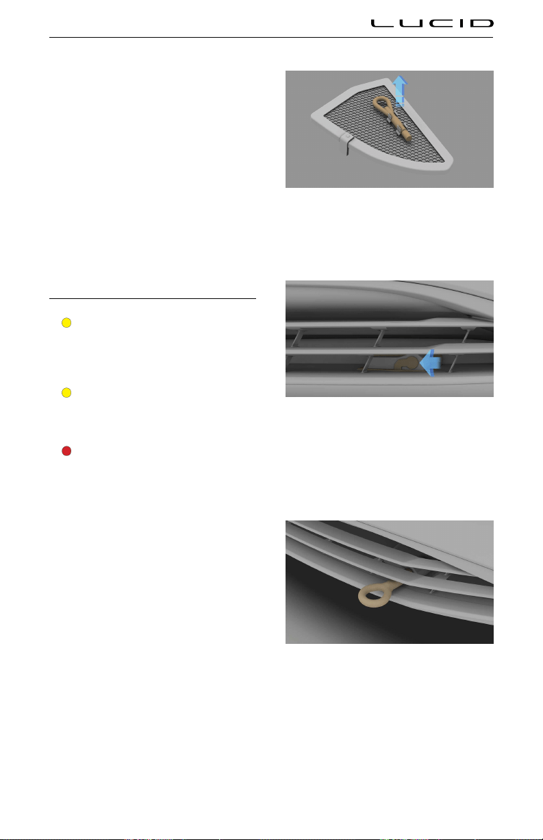
Tow Truck Mode
When loading and unloading the vehicle onto a
flatbed tow truck, put the vehicle in Tow Truck
Mode. This can be done on the Pilot Panel by
navigating to Settings > Vehicle and toling
Tow Truck Mode.
Tow Truck Mode disables the emergency
parking brake and shifts the vehicle into neutral
to allow it to be transported on and off the
flatbed truck.
Lucid recommends that Tow Truck Mode is
deactivated once the vehicle is loaded onto
the truck to re-engage the emergency parking
brake. Tow Truck Mode can also be deactivated
by pressing the brake pedal.
Pulling the Vehicle onto a Trailer or Transporter
CAUTION: Under no circumstances
should the vehicle be towed using
the vehicle recovery eye. Doing so
can cause significant damage to your
vehicle.
CAUTION: Incorrect installation of the
recovery eye can cause it to become
detached while pulling the vehicle,
resulting in significant damage.
WARNING: If the recovery eye mount
is not accessible and the vehicle
is recovered by attaching to a
frame, suspension, or other means,
the vehicle may sustain damage.
Inspect the vehicle and ensure it is
safe to operate.The Towing provider
MUST document the method of
vehicle recovery, whether using the
recovery eye, attachment to the body,
suspension, or other means.Failure to
do so could result in a hazardous
situation when operating the vehicle.
The recovery eye is available in the trunk of
your vehicle and located on the underside of
the right-hand floor panel.
To install the recovery eye:
1. Release the rubber cover from the
attachment point behind the front grille.
2. Position the recovery eye through the
bumper and rotate it clockwise into the
attachment point on the body until it
is fully seated. Visually check that the
recovery eye is parallel to the ground to
ensure correct installation.
3. Attach the winch cable to the recovery
eye.
4. Place the vehicle in Neutral (N) or support
rear wheels on a self-loading dolly (see
manufacturer instructions for use).
5. Pull the vehicle slowly onto the trailer or
transporter.
Roadside Assistance & Emergency Information 199

Note: After using the recovery eye, remember to
store it back in the trunk and install the rubber
cover on the attachment point.
Securing the Vehicle for Transportation
When the vehicle is in position on the
transporter or trailer, use chocks and tie-down
straps to secure the wheels.
To avoid damage:
- Ensure that metal parts on tie-down
straps do not contact the vehicle’s
painted surfaces or the face of any
wheels.
- Do not place straps over or through the
vehicle’s body panels.
CAUTION: Attaching straps to the
chassis, suspension, or other parts of
the body can damage the vehicle.
After securing the vehicle on the transporter or
trailer, use the Pilot Panel to select P (Park).
Doing so will engage the parking brake.
Roadside Assistance & Emergency Information 200

Disabling the Power System
Safety Precautions
WARNING: In the event of fire,
immediately contact your local fire
emergency responders.
WARNING: ALWAYS ASSUME THAT
HIGH-VOLTAGE COMPONENTS ARE
ENERGIZED. Cutting, crushing, or
touching high-voltage components can
result in serious injury or death.
WARNING: High-voltage cables and
components may remain energized for
up to 2 minutes after disabling.
WARNING: High-voltage batteries can
self-ignite even after extinguishing the
initial fire.
WARNING: The airbags and other
supplemental restraint systems may
remain powered for up to 2 minutes
after disabling.
WARNING: In the event of a fire
involving a charging station, treat it as
an energized electrical fire until power
to the charger is confirmed to shut off.
WARNING: This vehicle does not have
an internal combustion engine. Lack of
engine noise does not mean the vehicle
is OFF. Silent movement capability
exists until the vehicle completely shuts
down.
Emergency Responder Cut Loop
You can locate the emergency responder cut
loop under the hood on the right side, near the
suspension strut tower.
You can determine the location of the cut
loop by the yellow label wrapped around it.
This label is visible even with the maintenance
access panel in place.
Double cutting and removing the emergency
responder cut loop shuts down both the high-
voltage and the 12-volt battery systems.
Note: The cut loop is a low-voltage (12V) cable.
Roadside Assistance & Emergency Information 201

Vehicle Fire
Firefighting
WARNING: When a fire is involved,
consider the entire vehicle to be
energized. Always wear full personal
protective equipment (PPE), including
a self-contained breathing apparatus
(SCBA).
WARNING: Extinguishing any vehicle
fire is best accomplished by firefighting
professionals. Contact your local
authorities or fire department for help.
In the case of vehicle battery fire, exposure to
high heat, or presence of gases, USE LARGE
AMOUNTS OF WATER to cool it.
It can take copious amounts of water applied
directly to the battery to extinguish and cool
down a battery fire. Establish or request an
additional water supply from nearby sources.
In the absence of a water supply, use dry
chemicals, such as Carbon dioxide (CO2), foam,
or any other typical fire-extinguishing agent, to
fight the fire until a water supply is available.
Extinguishing smaller fires that do not involve
a high-voltage battery follows the standard
firefighting procedures.
A burning or a heated battery releases toxic
vapors. Responders should always protect
themselves with full PPE (including a SCBA)
and take appropriate measures to protect
civilians from the incident. Use fog streams
or positive-pressure ventilation fans (PPV) to
direct smoke and vapors away from other
responders and civilians.
After knock down
Make sure any fires are knocked down before
entering a hot zone. Heat combined with
flames can compromise the airbag inflators,
stored gas inflation cylinders, gas struts, and
other components, resulting in an unexpected
explosion.
During vehicle inspections, always use
insulated tools and do not make contact with
any high-voltage components.
Use a thermal imaging camera to measure
the temperature of the high-voltage battery
and monitor heating or cooling trends.
Before releasing the vehicle to second
responders (such as law enforcement or vehicle
transporters) or otherwise leaving the incident,
completely cool the battery with no fire, smoke,
or heating present for at least one hour. Always
notify second responders of the risk of battery
re-ignition.
Roadside Assistance & Emergency Information 202

New Vehicle Limited Warranty
Message to Customers
Welcome to the Lucid New Vehicle Limited
Warranty, and welcome to luxury electric. This
guide provides a detailed explanation of the
warranty terms for the Lucid Air, including
coverage types, durations, limitations, regions,
and more. Our goal is to provide peace of mind
and exceptional service at every step of the
Lucid Air ownership experience.
Who is the Warrantor?
Lucid USA, Inc. is the warrantor in the United
States and Lucid Motors Canada ULC is the
warrantor in Canada (collectively "Lucid”). Lucid
will provide repairs to Lucid Airs sold by and
delivered directly from Lucid or its affiliates
during the applicable warranty periods in the
specified Warranty Regions listed below in
accordance with the terms, conditions and
limitations in this Lucid New Vehicle Limited
Warranty.
Warranty Region Warrantor and Contact Information
USA
Lucid USA, Inc.
7373 Gateway Blvd
Newark, CA 94560
Phone: 1-888-99 LUCID
(1-888-995-8243)
Canada
Lucid Motors Canada ULC
Suite 2300, Bentall 5, 550
Burrard Street Vancouver BC,
V6C 2B5
Phone: 1-888-99 LUCID
(1-888-995-8243)
The Lucid New Vehicle Limited Warranty is
valid only within the region for which the Lucid
Air was originally manufactured and sold. Any
service required under the terms of this Lucid
New Vehicle Limited Warranty will be provided
by a Lucid Service Center.
You may take your Lucid Air temporarily to any
region where there is a Lucid Service Center,
and the Lucid Warranty will be honored in
that region. Temporary is defined as a period
less than six months. Proof of compliance with
any temporary import laws or regulations is
required. If you are permanently moving to
a new region supported by a Lucid Service
Center, you may apply to Lucid to transfer the
Lucid Warranty to the region for the duration of
your ownership. Requests to transfer a vehicle’s
Lucid Warranty will be decided on a case-by-
case basis by Lucid at its absolute discretion,
and will be subject to certain conditions,
including all necessary regional modifications
being carried out by a Lucid Service Center at
the owner’s cost.
Transfer of the Lucid Warranty to a new region
is not permitted for subsequent purchasers.
Lucid will not transfer the warranty coverage
following the sale of a vehicle within the new
region.
Who May Use This Limited Warranty?
This Lucid New Vehicle Limited Warranty
is provided to the original and subsequent
owner(s) of a new Lucid Air sold by Lucid or its
affiliates in a specific warranty region, titled or
registered in the name of the first retail owner
or subsequent owner. The Lucid New Vehicle
Limited Warranty can be transferred from the
original owner to a subsequent owner—the new
owner must provide proof of ownership transfer.
What Does This Limited Warranty Cover?
Your Lucid New Vehicle Limited Warranty gives
you specific legal rights. You may have other
rights that vary from jurisdiction to jurisdiction.
This Lucid New Vehicle Limited Warranty
provides limited warranty coverage for your
Lucid Air.
Under this Lucid New Vehicle Limited Warranty,
Lucid will, without charge and as determined
by Lucid at its discretion, repair, replace,
or adjust all parts on your new vehicle
that malfunction or fail during normal use
during the applicable coverage period due
to a manufacturing defect in factory-supplied
materials or factory workmanship provided
your vehicle has been properly operated and
maintained in accordance with all requirements
in the owner's manual and any other
documentation we may provide you, and was
Consumer Information 203

taken to a Lucid Service Center for a warranted
repair during the warranty period. It is the
responsibility of the owner of the vehicle to
present any concerns to a Lucid Service Center
in the Warranty Region in a timely manner.
The remedy under this Lucid New Vehicle
Limited Warranty, and any implied warranty, is
limited to repair, replacement, or adjustment
of defective parts. This exclusive remedy
shall not be deemed to have failed of its
essential purpose so long as Lucid, through
its authorized service centers, is willing and
able to repair, replace, or adjust defective
parts as described in this Lucid New Vehicle
Limited Warranty. Lucid’s liability, if any, shall
in no event exceed the cost of correcting
manufacturing defects as provided in this
written warranty. Upon expiration of this
warranty, any such liability shall terminate.
This Lucid New Vehicle Limited Warranty
agreement applies to vehicles manufactured
and sold by Lucid or its affiliates in the country
the vehicle was first purchased. The Lucid New
Vehicle Limited Warranty provides the following
types of coverage:
Warranty Type Coverage Duration
Vehicle 4 Years / 50,000 miles
Powertrain 8 Years / 100,000 miles
High Voltage
Battery
8 Years / 100,000 miles
retaining 70% capacity
Corrosion
Perforation
10 Years / Unlimited miles
Body and Paint
Repair
4 Years / Unlimited miles
Supplemental
Restraint System
(SRS)
5 Years / 60,000 miles
Lucid warrants each new vehicle in accordance
with the model version of the vehicle at the
time of production. Lucid reserves the right to
make modifications to vehicles manufactured
or sold by us at any time, without notice.
New Vehicle Limited Warranty
The New Vehicle Limited Warranty covers the
repair, replacement, or adjustment of parts
necessary to correct defects in the materials
or workmanship of any parts manufactured
or supplied by Lucid under normal use for a
period of four years or 50,000 miles (80,000
km), whichever comes first, subject to the
exclusions and limitations and the separate
coverage for certain parts described in this
New Vehicle Limited Warranty. In addition, any
repair, replacement, or adjustment of parts
or components is covered under this New
Vehicle Limited Warranty if damaged or made
inoperable due to a defect caused by a Lucid
over-the-air update during the warranty period.
If it is determined that your vehicle requires
warranty repair, Lucid will repair, replace, or
adjust the applicable vehicle part with a new,
reconditioned, or remanufactured part at the
discretion of Lucid.
Powertrain Limited Warranty
The Powertrain is covered for the duration
of 8 years or 100,000 miles (160,000 km),
whichever occurs first. The Powertrain Limited
Warranty will cover the cost of repair,
replacement, or adjustment of the defective
parts of the Lucid powertrain subject to
the limitations outlined in this New Vehicle
Limited Warranty. This coverage is for Lucid’s
sophisticated electric powertrain, including
the fully integrated electric drive units,
transmission, and differential.
If it is determined that your powertrain requires
warranty repair, Lucid will repair, replace, or
adjust the part with a new, reconditioned, or
remanufactured part at the discretion of Lucid.
Battery Limited Warranty
The high voltage battery is covered for the
duration of 8 years or 100,000 miles (160,000
km), whichever occurs first, with a minimum
70% retention of battery capacity over the
warranty period. The Battery Warranty covers
the cost of repair, replacement, or adjustment
of a defective Lucid battery at the discretion of
Lucid, subject to the limitations outlined in this
New Vehicle Limited Warranty.
The high voltage battery, like all batteries, will
experience a decrease of energy and power loss
with time and use. Loss of energy or power
reduction over time is not covered beyond
the terms and limits of this warranty,as set
forth in the paragraph above. Proper storage
and maintenance of your Lucid vehicle will
maximize the life and capacity of the battery.
Failure to follow the recommended guidelines
Consumer Information 204

and charging procedures as stated in the Lucid
Owner’s Manual will not be covered under the
terms of this limited warranty. Please refer to
the Owner’s Manual for additional information.
Please note that the vehicle’s displays of range
are estimates based on driving conditions
and habits, including other factors that
are independent from the vehicle’s battery
capacity. The measurement method used to
determine the battery capacity is at the sole
discretion of Lucid’s trained and authorized
representatives.
If it is determined that your battery requires
warranty repair, Lucid will repair, replace, or
adjust the part with a new, reconditioned, or
remanufactured part at the discretion of Lucid.
However, Lucid will ensure that the capacity of
the battery will be equal or greater than the
original battery capacity during the warranty
claim.
Corrosion Perforation Limited Warranty
The Lucid Corrosion Perforation Limited
Warranty covers perforation of body panels
from within to the outside of the panel resulting
from a material or manufacturing defect for 10
years (there is no mileage limitation on this
coverage), except where:
- Surface corrosion occurs due to paint
damaged by scratches, stone chips,
or environmental fallout such as bird
droppings or acid rain.
- The application of non-Lucid approved
third-party coatings that have a
detrimental effect on the original painted
surface or under body panels.
- Corrosion is caused by, due to, or
resulting from accidents, abuse, neglect,
improper maintenance or operation of the
vehicle, installation of a non-approved
accessory, exposure to chemicals or
environmental contaminants, damage
resulting from an act of God or nature,
fire, or improper storage.
- Damage is due to lack of required
maintenance; improper maintenance; the
use of other than original equipment
parts, non-approved parts, or fluids; or
improper body repairs.
- Repairs have not been performed by a
Lucid Service Center or Lucid approved
body shop.
Supplemental Restraint System (SRS) Limited Warranty
The Supplemental Restraint System Limited
Warranty covers defects in the seat belts or
air bags system resulting from material or
manufacturing defect for 5 years or 60,000
miles (100,000km), whichever comes first.
What Does This Limited Warranty Not Cover?
Wear and Tear Items
The Lucid New Vehicle Limited Warranty does
not cover any item where its failure is due
to normal wear and tear or items that have
to be replaced or adjusted periodically during
routine servicing and maintenance, including
paint and glass chips, key fob batteries,
upholstery discoloration, tears, punctures,
wrinkles, depressions or other similar items.
The term “wear and tear” describes the normal
process by which the components reach the
limit of serviceability through normal use. The
service life of a wearing part depends on the
type of use of the vehicle and individual style
of driving. As such, any component which
has been repaired, replaced, or adjusted once
under this Lucid New Vehicle Limited Warranty
is not covered again, unless the failure is due to
a manufacturing defect.
Items subject to normal wear and tear include,
but are not limited to:
- Brake discs and pads
- Wiper blades
- Seat and back rest covers
- Upholstery and trim
- Steering Wheel
- Floor coverings
Service parts include, but are not limited to:
- Filters
- Lubricants
Consumer Information 205

- Items replaced during routine
maintenance
Service adjustments required after the first
service, including but not limited to:
- Adjustment to doors and hoods
- Head lamp adjustment
- Wheel alignment
- Wheel balancing
Tires
The original factory fitted tires are covered
against manufacturing defects by the tire
manufacturer, who provides a separate
warranty to you with its own terms and
conditions. Warranty claims must be made
directly with the tire manufacturer. The Lucid
New Vehicle Limited Warranty does not cover
tires.
Performance Modifications
The Lucid New Vehicle Limited Warranty
does not cover any repair, replacement, or
adjustment of parts where the fault or defect
is wholly or partially attributed to performance
related modifications.
Performance Metrics
Performance metrics advertised by Lucid
and/or other testing agencies are not covered
under the Lucid New Vehicle Limited Warranty
as there are many variables that may affect the
vehicle performance, including but not limited
to vehicle age/use, ambient temperature,
battery state of charge. Please refer to the
Owner’s Manual for additional information.
Removal of Non-Standard Equipment or
Accessories
Additional labor time for the removal of non-
standard equipment, including but not limited
to aftermarket parts and accessories, and Lucid
Accessories cannot be claimed under the Lucid
New Vehicle Limited Warranty.
Track and Competition Use
Track and Competition use is not covered
under the Lucid New Vehicle Limited Warranty.
Normal Noise and Vibration
All mechanical devices produce some level
of noise and/or vibration that can differ
between vehicles. Slight wind noise, component
noise, and/or vibration that do not affect the
performance of the vehicle are considered
normal and are not covered by the Lucid New
Vehicle Limited Warranty.
Commercial Use as a Taxi or Ride Sharing
Service
The Lucid New Vehicle Limited Warranty does
not cover Lucid vehicles being used to provide
taxi or ride sharing services.
Insurance Write-off
A Lucid vehicle is not covered by the Lucid
New Vehicle Limited Warranty if the vehicle
has been damaged to such an extent that
an insurer, financing institution, or leasing
company determines the Lucid vehicle to be
a "total loss," "write off," or equivalent. This
includes, but is not limited to, vehicles branded
as "salvage," "scrap," "dismantled," or similar
titles.
Other Damage
Damage caused by any of the following items or
actions listed below is not covered under this
Lucid New Vehicle Limited Warranty:
- Accidents, collision or objects striking the
vehicle
- Theft, vandalism, or riot
- Vehicle damage due to external incidents
- Customer-applied chemicals or
accidental spills, including sunscreen or
hairspray
- Driving through water deep enough
to cause water to infiltrate into any
component, for example, powertrain
components
- Installation of parts that are not Lucid
Genuine Parts
- Immersion/flooding of the high voltage
battery assembly
- Abuse and/or misuse of the vehicle
and/or high voltage battery pack, such as
Consumer Information 206

driving over curbs, overloading, racing or
track use
- Any unauthorized access or modification
of vehicle software or data through
the use of, but not limited to, non-
Lucid software programs, malware,
programming errors, or any electronic
disruptions.
- Permitting water to enter the vehicle by
leaving a window or door open
- Exceeding the load limits specified on the
certification label
- Failure to observe and resolve vehicle
warnings and indications of battery
concerns within a reasonable amount of
time
- Failure to complete software updates
within a reasonable amount of time,
typically 30 days
- The use of incompatible charging devices
or methods
- Modifications to the vehicle, high voltage
battery assembly, high voltage system, or
associated wiring
- Exposure to direct and/or intense heat
sources outside of normal use
- Allowing the high voltage battery
assembly to remain in a fully discharged,
or near zero state of charge, for more than
14 days
- Repairs performed by facilities and
personnel not authorized by Lucid,
including repairs which would have
otherwise been covered under this Lucid
New Vehicle Limited Warranty
- Improper vehicle storage resulting in high
voltage battery damage
What Will Cause the Warranty to Be Voided?
The Lucid New Vehicle Limited Warranty will
be voided, and no warranty coverage will be
provided in the following situations:
- Failing to properly operate your vehicle in
accordance with the specific instructions
and recommendation regarding the use
and operation of your vehicle as provided
in the Owner’s Manual.
- Failing to install required software
updates within 30 days after notification
that an update is available.
- Failing to comply with any recall notice.
- Defacing or altering the VIN or odometer
or any related system such that it is
difficult to determine the VIN number or
actual mileage.
- The vehicle being sold, designated,
labeled or branded as dismantled, fire-
damaged, flood-damaged, junk, rebuilt,
salvage, reconstructed, irreparable, or a
total loss, including a determination by an
insurance carrier that the vehicle is a total
loss.
What to do if you need Roadside Assistance?
To obtain roadside assistance when your Lucid
vehicle is inoperable, contact 1-888-995-8243.
Roadside Assistance is an additional service
offered by Lucid for four years or 50,000 miles,
whichever comes first. It is a separate service
and is not provided as part of the New Vehicle
Limited Warranty. See Roadside Assistance &
Emergency Information on page 197for more
information.
What is the Coverage Period?
Coverage under this Lucid New Vehicle Limited
Warranty begins on the date that the vehicle
is delivered to the first retail or corporate
purchaser (s) or lessor (s) or the day it is first
put into service (in the case of demonstrator
vehicle), whichever occurs first and lasts until
the time period as stated in the New Vehicle
Warranty Coverage section of this guide.
What Are Your Remedies?
The Lucid New Vehicle Limited Warranty covers
the rectification of reported defects covered
by this warranty via repair, replacement, or
adjustment of faulty parts or components, as
determined by Lucid in its discretion. If a defect
can be properly eliminated by repair, and this
is the most economical course of action, then
the Lucid Service Representative will complete
the repair. Lucid may determine at its sole
discretion that certain parts or components
should be replaced rather than repaired.
Consumer Information 207

For Lucid Genuine Spare Parts installed during
a warranty repair, the warranty coverage ends
at the expiration of the warranty period for that
covered system.
For reported defects in the materials or
workmanship of any parts manufactured or
supplied by Lucid but not remedied within the
warranty period, the Lucid Warranty coverage
for that reported defect will continue until the
reported defect is resolved. Such coverage will
end:
- When the Lucid Service Representative
confirms that the defect has been
eliminated;
- When the Lucid Service Representative
confirms that no fault exists; or
- Thirty days after you have been notified
in writing that the Lucid Genuine Spare
Parts required to carry out the repair
are in stock at the Lucid Service
Representative.
Limitations on Liability
To the fullest extent allowed by applicable law,
all of the warranties in this Lucid New Vehicle
Limited Warranty are subject to the following
limitations and disclaimers:
THE WARRANTIES IN THIS LUCID NEW
VEHICLE LIMITED WARRANTY ARE THE
ONLY EXPRESS WARRANTIES APPLICABLE TO
YOUR VEHICLE. LUCID DOES NOT ASSUME
OR AUTHORIZE ANYONE TO ASSUME FOR
IT ANY OTHER OBLIGATION OR LIABILITY
IN CONNECTION WITH YOUR VEHICLE OR
THESE WARRANTIES. NO PERSON MAY
MODIFY OR WAIVE ANY PART OF THESE
WARRANTIES.
As a condition of these warranties, you are
responsible for properly using, maintaining, and
caring for your vehicle as outlined in your
Owner’s Manual. Lucid recommends that you
maintain copies of all maintenance records and
receipts for review by Lucid.
Any implied warranty of merchantability or
fitness is limited, to the fullest extent allowed
by applicable law, to the time period covered by
these written warranties, or to the applicable
time period provided by applicable law,
whichever period is shorter.
To the fullest extent allowed by applicable law,
Lucid disclaims all implied warranties if the
vehicle is used for business or commercial
purposes. To the fullest extent allowed by
applicable law, Lucid disclaims the implied
warranty of fitness for a particular purpose
if your vehicle is used for racing, even if the
vehicle is equipped for racing.
The warranties contained in this Lucid New
Vehicle Limited Warranty and all questions
regarding their enforceability and interpretation
are governed by the law of the jurisdiction in
which you purchased your Lucid vehicle. Some
jurisdictions do not allow Lucid to limit how
long an implied warranty lasts or to exclude or
limit incidental or consequential damages, so
the limitation and exclusions described above
may not apply to you.
Lucid reserves the right to make changes in
or additions to warranties for vehicles built or
sold by them at any time without incurring
any obligation to make the same or similar
changes or additions to warranties for vehicles
previously built or sold.
Lucid also reserves the right to provide post-
warranty repairs, conduct recalls, or extend the
warranty coverage period for certain vehicles
or vehicle populations, at the sole discretion
of Lucid. The fact that Lucid has provided
such measures to a particular vehicle or vehicle
population in no way obligates Lucid to provide
similar measures to other owners of similar
vehicles.
Dispute Resolution
We take customer satisfaction seriously. If
you have any questions or concerns, or are
unsatisfied with the service you are receiving,
follow these steps:
1. Contact your Lucid Service
Representative at your local Service
Center
2. If your inquiry or concern remains
unresolved, contact the Sales Manager,
Service Manager or Customer
Care Manager at 1-888-99 LUCID
(1-888-995-8243)
What to Do in Case of Dispute
Customer satisfaction is very important to
Lucid. If you have an unresolved warranty
concern after following the procedure outlined
above, U.S. owners may be eligible to utilize
Consumer Information 208

the BBB AUTO LINE, an out of court dispute
resolution program administered by BBB
National programs.
BBB AUTO LINE, administered by BBB
National Programs
1676 International Drive, Suite 550
McLean, Virginia 22102
1-800-955-5100 or BBBAUTOLINE.org
This service is provided at no cost to you and
is part of Lucid's effort to provide you with an
impartial third-party organization to equitably
resolve your concerns. BBB AUTO LINE
provides voluntary mediation and non-binding
arbitration services for disputes involving
Lucid vehicles with an alleged nonconformity,
defect, or deficient warranty performance, as
determined by state or federal law.
You must bring the alleged defect to the
attention of Lucid or an authorized Lucid dealer
within the eligibility period defined by your
local state law.
IMPORTANT: YOU MUST USE BBB AUTO
LINE PRIOR TO SEEKING REIMBURSEMENT
AVAILABLE TO YOU THROUGH A COURT
ACTION PURSUANT TO THE MAGNUSON-
MOSS WARRANTY ACT ("THE ACT").
HOWEVER, IF YOU CHOOSE TO SEEK
REMEDIES THAT ARE NOT CREATED BY THE
ACT, YOU ARE NOT REQUIRED TO USE BBB
AUTO LINE, ALTHOUGH THAT OPTION IS
STILL AVAILABLE TO YOU. IN ADDITION, YOU
MUST USE BBB AUTO LINE IF YOU ARE
REQUIRED TO DO SO PRIOR TO SEEKING
REMEDIES UNDER THE "LEMON LAW" OF
YOUR STATE, IF YOUR STATE REQUIRES YOU
TO DO SO. PLEASE CONSULT THE BBB AUTO
LINE PROGRAM FOR ELIGIBILITY AND TIME
LIMITATIONS IN YOUR STATE.
Please consult specific state laws for guidance
about your specific state lemon law. However,
if your state law permits, and if you choose to
seek remedies that are not created by the Act,
you are not required to use BBB AUTO LINE,
although that option is still available to you.
NOTE: If your state law requires written
notification to the manufacturer please write to:
Lucid Customer Care Center
7373 Gateway Boulevard
Newark, CA 94560
To begin the Alternative Dispute Resolution
(arbitration) process, simply call BBB
AUTO LINE at 1-800-955- 5100 or visit
BBBAUTOLINE.org to file a claim online. You
will be provided a Customer Claim Form, along
with information describing how BBB AUTO
LINE works. Your vehicle’s age, mileage and
other limitations may apply. If you wish to use
the BBB AUTO LINE program and you qualify
for participation, you will be required to provide
the following information:
- Your name and address;
-
The vehicle identification number;
-
The make, model and year of your vehicle;
and
- A description of your concerns with the
vehicle.
BBB AUTO LINE may also ask you for other
information to help resolve your concerns,
such as the purchase price of the vehicle, the
mileage at the time of purchase, the current
mileage and copies of repair orders. Upon
receipt of your properly completed Customer
Claim Form, BBB AUTO LINE will facilitate
a voluntary mediation process for possible
mutual resolution. If a mutual resolution is
not possible, the matter will be resolved by
non-binding arbitration. A decision is normally
rendered within 40 days. BBB AUTO LINE
will provide you a copy of the arbitrator's
decision and, if you accept the decision,
all parties must comply with the decision
within the time limits (performance date) set
by the arbitrator. Approximately two weeks
after the "performance date," BBB AUTO LINE
will contact the consumer to verify that the
arbitrator's decision has been completed.
BBB AUTO LINE's decisions do not include
attorney's fees, civil penalties, punitive
damages, multiple damages or consequential
damages other than incidental damages which
you may be entitled to under law. If you reject
the decision of the arbitrator, you may pursue
other legal remedies under state or federal
law, and the company will not be obligated to
perform any part of the decision. Depending
on federal or state law, the decision may or
may not be introduced as evidence by the
consumer or the company in any civil court
action relating to any matter that has been
resolved in your arbitration hearing, and BBB
AUTO LINE involvement in the case will end as
well.
Consumer Information 209

Customer Care
Contacting Lucid Motors
Please have the following details available
when contacting Lucid Motors. They are
essential to effectively and efficiently answer
your questions or resolve your concerns.
- Owner’s name and address
- Owner’s telephone number
- Vehicle identification number (VIN)
Contact Lucid Motors using the information
for your warranty region shown earlier in this
section or as follows:
Lucid Motors
7373 Gateway Blvd
Newark, CA 94560
USA
Phone:
+1 (888) 995-8243
Monday-Friday 8 am to 5 pm (Pacific Time)
E-mail: [email protected] (24 hours)
For updates and additional information about
your vehicle, visit the owner resources
section of the Lucid Motors website:
www.lucidmotors.com
Consumer Information 210

Reporting Safety Defects
United States
If you believe that your vehicle has a defect
which could cause a crash or could cause
injury or death, you should immediately
inform the National Highway Traffic Safety
Administration (NHTSA) in addition to notifying
Lucid Motors.
If NHTSA receives similar complaints, it may
open an investigation, and if it finds that a
safety defect exists in a group of vehicles,
it may order a recall and remedy campaign.
However, NHTSA cannot become involved in
individual problems between you and Lucid
Motors.
To contact NHTSA, you may call the Vehicle
Safety Hotline toll-free at:
1-888-327-4236 (TTY: 1-800-424-9153); go to
http://www.safercar.gov; or write to:
Administrator
National Highway Traffic Safety Administration
1200 New Jersey Avenue SE
Washington, DC 20590
You can also obtain other information about
motor vehicle safety from:
http://www.safercar.gov
Canada
If you believe that your vehicle has a defect
which could cause a crash or could cause
injury or death, you should immediately inform
Transport Canada, in addition to notifying
Lucid Motors.
To contact Transport Canada, call their toll-free
number:
+1-800-333-0510
Consumer Information 211

Disclaimers
California Proposition 65
WARNING: Operating, servicing, and
maintaining a passenger vehicle can
expose you to chemicals, including
phthalates, which are known to
the State of California to cause cancer
and birth defects, or other reproductive
harm. To minimize exposure, wear gloves or
wash your hands frequently when servicing
your vehicle. For more information, go to
www.P65Warnings.ca.gov/passenger-vehicle.
California Perchlorate Advisory
WARNING: Certain components of this
vehicle, such as lithium batteries, may
contain perchlorate material. Special
handling may apply for service or end-
of-life disposal. See www.dtsc.ca.gov.
Vehicle Telematics
Lucid Air is an advanced connected vehicle
equipped with a host of advanced electronic
control units (ECUs), each responsible for
a specific set of features. The features
span domains including controls, safety,
infotainment, chassis, AD/ADAS, telematics, to
name a few that contribute to functionality,
performance, safety, and security of the vehicle.
In the process of its operation, each ECU
monitors a set of sensors and controls a set
of actuators depending on the role of the ECU.
As a result, each ECU generates and collects
data about the operational state, performance,
anomalies, environment conditions, battery and
charging related information, speed, direction,
location, etc. The collected data are transmitted
to the Lucid cloud services infrastructure on
an ongoing basis over cellular wireless and
wireless LAN networks. In addition, a portion
of the data may be accessed by the technicians
at the service center and stored in the Lucid
information databases.
Lucid may use the vehicle data stored in
the vehicle, databases in the service centers,
and cloud-based infrastructure to enhance its
products and services, including but not limited
to vehicle maintenance, trouble-shooting,
timely service recommendations & reminders,
additional feature recommendations, research
and development, and marketing & business
analysis purposes. Lucid Air has the over-the-
air (OTA) software update capability to keep the
vehicle software current and improved. Lucid
may use the vehicle data to update vehicle
software improvements OTA to avoid issues
proactively before they occur on the vehicle.
Please see Lucid's Vehicle Data Privacy Policy
and Privacy Policy for additional details
about how Lucid collects and processes data
collected from the vehicle.
Consumer Information 212

Vehicle Recycling
High-Voltage Battery Recycling Process
WARNING: Attempting to disconnect or
remove the battery pack without the
proper training, tools, and equipment
is highly dangerous and could result in
serious injury or death.
Your vehicle is equipped with a liquid-cooled
lithium ion (Li-ion) high-voltage battery pack. A
battery pack must be properly recycled when it
has been damaged or has reached the end of
its useful service life.
If the vehicle can no longer hold a charge
or power on, or in the case of a collision or
submersion, contact a Lucid Service Center
immediately. Have the battery pack removed
from the vehicle by a Lucid Service Center or a
Lucid approved technician as soon as possible.
Do not attempt to disconnect or remove the
battery pack yourself.
Lucid Service Centers will manage the
damaged or depleted battery pack and, in
accordance with Lucid’s requirements, contact
a qualified recycling company for recycling and
disposal.
Environmental: Do not dispose of the battery
pack yourself, as arbitrary disposal can cause
pollution and harm to the environment.
Be sure to follow the information and
requirements below:
1. Personnel: The HV battery removal
operation must be performed by a Lucid
Service Center technician or a Lucid-
approved professional.
2. Transportation: The battery pack is
classified as a hazardous material under
Class 9 dangerous goods. If removed
from the vehicle, these must be labeled,
documented, and transported by licensed
vehicles that meet all requirements for
transporting Class 9 dangerous goods.
3. Storage: The removed battery pack
should be stored in an environment that
is protected from extreme temperatures
and high humidity. Do not expose the
removed battery pack to flammable
materials, heat sources, water sources, or
other hazards.
For questions or further details on the
recycling and disposal of a battery pack,
please contact a Lucid Service Center.
To locate a Lucid Service Center, please
visit www.lucidmotors.com for the latest
information.
Consumer Information 213

FCC and FDA Compliance
FCC Certification
Component Manufacturer Model Operating Frequency (MHz) FCC ID
Bluetooth® Vehicle
Key
Pektron Group
Ltd
013 2402-2480 MHz AQO013
Access Control
Module BTLE/LF
Node
Pektron Group
Ltd
012 125 KHz, 2402-2480
MHz
AQO012
Access Control
Module
BTLE/LF/NFC
Node
Pektron Group
Ltd
011 125 KHz, 13.56 MHz,
2402-2480 MHz, 13.56
MHz
AQO011
Center Console
Controller
Lucid USA, Inc. K2B000 2402-2480 MHz,
5180.0-5240.0 MHz,
5260-5320 MHz,
5745.0-5825.0 MHz
2AXZJ-K2B000
Homelink Universal
Garage Door
Transmitter
Gentex Corp ADHL5D 286-440 MHz, 902-927
MHz
NZLADHL5D
Long-Range Radar Automotive
Distance Control
Systems GmbH
OAYARS5B 76-77 GHz OAYARS5B
Wireless Phone
Charger
JVIS USA LLC 1LCID350001 119.6 KHz 2AZX6-1LCID350001
Short Range Radar Automotive
Distance Control
Systems GmbH
OAYSRR5B 76-77 GHz OAYSRR5B
Telematics Control
Unit
Lucid USA, Inc. CTX0700 2412.0-2462.0 MHz,
2502.5-2567.5 MHz,
5180.0-5240.0 MHz,
5745.0-5825.0 MHz,
699.7-715.3 MHz,
779.5-784.5 MHz,
824.2-848.8 MHz,
1710.7-1754.3 MHz,
1850.2-1909.8 MHz
2AXZJ-CTX0700
Tire Pressure
Monitoring System
Continental
Automotive
GmbH
TIS-01 433.92 MHz KR5TIS-01
FCC Notes: Wireless Charger-JVIS USA
FCC ID: 2AZX6-1LCID350001
This device complies with part 15 of the FCC Rules. Operation is subject to the following two
conditions:
1. This device may not cause harmful interference.
2. This device must accept any interference received, including interference that may cause
undesired operation.
Consumer Information 214

Changes or modifications not expressly approved by the party responsible for compliance could void
the user's authority to operate the equipment.
This equipment has been tested and found to comply with the limits for a Class B digital device,
pursuant to part 15 of the FCC Rules. These limits are designed to provide reasonable protection
against harmful interference in a residential installation. This equipment generates, uses, and can
radiate radio frequency energy and, if not installed and used in accordance with the instructions, may
cause harmful interference to radio communications. However, there is no guarantee that interference
will not occur in a particular installation. If this equipment does cause harmful interference to radio
or television reception, which can be determined by turning the equipment off and on, the user is
encouraged to try to correct the interference by one or more of the following measures:
- Reorient or relocate the receiving antenna.
- Increase the separation between the equipment and receiver.
- Connect the equipment into an outlet on a circuit different from that to which the receiver is
connected.
- Consult the dealer or an experienced radio/TV technician for help.
FCC Notes: TPMS System – Continental Automotive GmbH
FCC ID: KR5TIS-01
FCC Statements
FCC § 15.19 Labelling requirements
This device complies with part 15 of the FCC Rules and Industry Canada license-exempt RSS
standard(s). Operation is subject to the following two conditions:
1. This device may not cause harmful interference.
2. This device must accept any interference received, including interference that may cause
undesired operation.
FCC § 15.21 Information to user
Changes or modifications not expressly approved by the party responsible for compliance could void
the user’s authority to operate the equipment.
FCC Notes: Universal Garage Door Opener Transmitter – Gentex Corp.
FCC ID: NZLADHL5D
FCC (USA) and IC (Canada):
This device complies with FCC rules part 15 and Industry Canada RSS-210. Operation is subject to the
following two conditions:
1. This device may not cause harmful interference.
2. This device must accept any interference that may be received ,including interference that may
cause undesired operation.
WARNING: The transmitter has been tested and complies with FCC and IC rules.
Changes or modifications not expressly approved by the party responsible for
compliance could void the user’s authority to operate the device.
Consumer Information 215

This equipment complies with FCC radiation exposure limits set forth for an uncontrolled environment.
End users must follow the specific operating instructions for satisfying RF exposure compliance.
This transmitter must be at least 20cm from the user and must not be co-located or operating in
conjunction with any other antenna or transmitter.
FCC Notes: Long Range Radar - Automotive Distance Control Systems GmbH
FCC ID: OAYARS5B IC: 4135A-ARS5B
Canada only:
This device complies with Industry Canada licence-exempt RSS standard(s). Operation is subject to
the following two conditions:
1. This device may not cause harmful interference, and
2. This device must accept any interference received, including interference that may cause
undesired operation.
Le présent appareil est conforme aux CNR d'Industrie Canada applicables aux appareils radio exempts
de licence. L'exploitation est autorisée aux deux conditions suivantes:
1. l'appareil ne doit pas produire de brouillage, et
2. l'utilisateur de l'appareil doit accepter tout brouillage radioélectrique subi, même si le brouillage
est susceptible d'en compromettre le fonctionnement.
Canada & US:
Radiofrequency radiation exposure Information: This equipment complies with FCC and IC radiation
exposure limits set forth for an uncontrolled environment. This equipment should be installed and
operated with a minimum distance of 20 cm between the radiator and your body.
This transmitter must not be co-located or operating in conjunction with any other antenna or
transmitter.
Cet équipement est conforme aux limites d'exposition aux rayonnements IC établies pour un
environnement non contrôlé. Cet équipement doit être installé et utilisé avec un minimum de 20 cm de
distance entre la source de rayonnement et votre corps.
US: FCC Notice
Changes or modifications not expressly approved by the party responsible for compliance could void
the user's authority to operate the equipment.
FCC Notes: Short Range Radar Model: SRR5-B - Automotive Distance Control Systems GmbH
FCC ID: OAYSRR5B
Radiofrequency radiation exposure Information:
This equipment complies with FCC radiation exposure limits set forth for an uncontrolled environment.
This equipment should be installed and operated with a minimum distance of 20 cm between the
radiator and your body.
This transmitter must not be co-located or operating in conjunction with any other antenna or
transmitter.
FCC Notice
Consumer Information 216

Changes or modifications not expressly approved by the party responsible for compliance could void
the user's authority to operate the equipment.
FCC Note: Bluetooth Vehicle Key, ACM Node BTLE/LF, ACM Node BTLE/LF/NFC - Pektron Group
FCC ID: AQO013, AQO012, AQO011
US
This device complies with Part 15 of the FCC Rules.
Operation is subject to the following two conditions:
1. This device may not cause harmful interference.
2. This device must accept any interference received, including interference that may cause
undesired operation.
This equipment complies with FCC radiation exposure limits set forth for an uncontrolled environment.
End-users must follow the specific operating instructions for satisfying RF exposure compliance. This
transmitter must not be co-located or operating in conjunction with any other antenna or transmitter.
Changes or modifications not expressly approved by the party responsible for compliance could void
the user's authority to operate the equipment.
FCC Notes: TCU – Lucid USA, Inc.
FCC ID: 2AXZJ-CTX0700
FCC Interference Statement
This equipment has been tested and found to comply with limits for a Class B digital device, pursuant
to Part 15 of the FCC rules. These limits are designed to provide reasonable protection against
harmful interference in a residential installation. This equipment generates, uses, and can radiate
radio frequency energy and, if not installed and used in accordance with the instructions, may cause
harmful interference to radio communications. However, there is no guarantee that interference will
not occur in a particular installation. If this equipment does cause harmful interference to radio
or television reception, which can be determined by turning the equipment off and on, the user is
encouraged to try and correct the interference by one or more of the following measures:
- Reorient or relocate the receiving antenna.
- Increase the separation between the equipment and receiver.
- Connect the equipment into an outlet on a circuit different from that which the receiver is
connected.
- Consult the dealer or an experienced radio/TV technician for help.
FCC Caution: Any changes or modifications not expressly approved by the party responsible for
compliance could void the user’s authority to operate this equipment.
This device complies with Part 15 of the FCC Rules. Operation is subject to the following two
conditions:
1. This device may not cause harmful interference, and
2. This device must accept any interference received, including interference that may cause
undesired operation.
Consumer Information 217

This device and its antenna(s) must not be co-located or operating in conjunction with any other
antenna or transmitter.
For products available in the USA/Canada market, only channel 1-11 can be operated. Selection of
other channels is not possible.
IMPORTANT NOTE:
FCC Radiation Exposure Statement:
This equipment complies with FCC radiation exposure limits set forth for an uncontrolled environment.
This equipment should be installed and operated with a minimum distance of 25cm between the
radiator & your body.
FCC Notes: Center Console Controller – Lucid USA, Inc
FCC ID: 2AXZJ-K2B000
FCC Interference Statement
This device complies with part 15 of the FCC Rules. Operation is subject to the following two
conditions:
1. This device may not cause harmful interference.
2. This device must accept any interference received, including interference that may cause
undesired operation.
Changes or modifications made to this equipment not expressly approved by Lucid Motors, Inc. may
void the FCC authorization to operate this equipment.
FCC Radiation Exposure Statement
This equipment complies with FCC radiation exposure limits set forth for an uncontrolled environment.
This equipment should be installed and operated with a minimum distance of 25cm between the
radiator and your body.
Event Data Recorder
This vehicle is equipped with an event data recorder (EDR). The main purpose of an EDR is to record,
in certain crash or near crash-like situations, such as an airbag deployment or hitting a road obstacle,
data that will assist in understanding how a vehicle's systems performed. The EDR is designed to
record data related to vehicle dynamics and safety systems for a short period of time, typically 30
seconds or less. The EDR in this vehicle is designed to record such data as:
- How various systems in your vehicle were operating;
- Whether or not the driver and passenger safety belts were buckled/fastened;
- How far (if at all) the driver was depressing the accelerator and/or brake pedal; and,
- How fast the vehicle was traveling.
These data can help provide a better understanding of the circumstances in which crashes and
injuries occur.
Note: EDR data are recorded by your vehicle only if a non-trivial crash situation occurs; no data are
recorded by the EDR under normal driving conditions, and no personal data (e.g., name, gender, age,
and crash location) are recorded. However, other parties, such as law enforcement, could combine the
EDR data with the type of personally identifying data routinely acquired during a crash investigation.
Consumer Information 218

To read data recorded by an EDR, special equipment is required, and access to the vehicle or the EDR
is needed. In addition to the vehicle manufacturer, other parties, such as law enforcement, that have
the special equipment, can read the information if they have access to the vehicle or the EDR.
Food and Drug Administration (FDA) Compliance Information
WARNING: DO NOT attempt to remove, access, or modify the LiDAR unit in this vehicle. The
LiDAR unit is a Class I laser device subject to regulation by the FDA. There are NO permitted
service or maintenance procedures for your vehicle’s LiDAR. If you suspect that the LiDAR unit
is not functioning properly, contact Lucid immediately for instructions.
Vehicle Patents
A list of Lucid Air patents can be found at www.lucidmotors.com/legal.
Consumer Information 219

Index
A
Accessory mode
68
Adaptive Cruise Control 98
Air filter replacement 157
Airbags 53
Obstruction of 56
Warning indicator 59
Alerts and notifications 60
Anti-Lock Braking System (ABS) 80
Anti-theft system 37
Audio
Physical controls 123
Playing from devices 127
Settings 127
Automatic parking
Autonomous Park In 111
Autonomous Park Out 113
Distance warning 116
B
Batteries (12V)
Maintenance
163
Specifications 196
Battery (high-voltage) 143
Charging 144
Emergency disabling 201
Health 143
Specifications 196
Temperature limits 143
Battery (key fob) 26
Blind Spot Display 110
Blind Spot Monitoring 109
Bluetooth®
Pairing 131
Playing media 127
Using a paired phone 132
Body repairs 171
Brake fluid 153
Brakes
Anti-Lock Braking System (ABS) 80
Brake pad wear 82
Comfort braking 117
Emergency braking 106
Lucid Stability Control 84
Regenerative braking 81
Specifications 193
Stopping Mode 81
C
Cameras
Limitations 93
Rear view 116
Surround view 115
Car cover 160
Car washes 158
Cargo area
Folding the rear seat 40
Front 34
Pass-through hatch 40
Rear 36
Charge port 144
Light 146
Manually open 145
Charging
Instructions 145
Safety checklist 144
Set charge limit 147
Status 146
Temperature limits 147
Charging cable 144
Emergency manual release 146
Child restraints
Automatic Locking Retractor (ALR) 45
Child safety locks 30
Child safety seats
Booster seats 49
Choosing a seat 48
Guidelines 48
Installation 49
Cleaning
Carpets and floor mats 161
Displays 160
Exterior 158
Interior 160
Underbody 159
Wheels 159
Windshield, windows, and mirrors 159
Wiper blades 159
Collision repairs 171
Collision warning 106, 108
Contact information
Lucid Motors 210
Lucid Roadside Assistance 197
NHTSA 211
Transport Canada 211
Cross Traffic Protection 108
Cruise control 98
Cut loop 201
D
Data
Personal
17
Delivery mileage 17
Displays
Cleaning
160
Glass Cockpit 23
Pilot Panel 23, 24
Smart drawer 24
Distracted Driver Alert 104
Doors
Automatic locking and unlocking 30

Doors (continued)
Child safety locks 30
Opening and closing 29
Opening with no power 30
Download
Owner’s Manual 138
Software updates 139
DreamDrive
Limitations 93
Requirements 98
Steering wheel controls 97
Drive Mode 68
Drowsy Driver Alert 104
E
Emergency braking
106
F
Face login
120
Firefighting 202
Flatbed transporting 200
Floor mats 162
Cleaning 161
Forward Collision Warning 106
Front passenger detection 56
Front suspension specifications 194
H
Hauling your vehicle
200
Head restraints
Adjusting 42
Positioning 42
Reinstalling 43
Removing 43
Highway Assist 100
HomeLink® 135
Hood 33
Interior emergency release 34
I
Indicator lights
Airbag
59
Autonomous Emergency Braking 106
Low tire pressure 183
Intrustion Alert 37
K
Key fob
Battery replacement 26
Care instructions 27
Low battery indicator 26
Replacement 27
Troubleshooting 25
Key fob (continued)
Using 25
L
Label
Cut loop
201
Tire and loading information 177
Vehicle certification 187
Lane Departure Protection 108
Load carrying 185
Locking your vehicle 25
M
Maintenance
Brake fluid
153
Daily and monthly checks 148
Service intervals 150
Underbody 159
Washer fluid 154
Wiper blades 155
Maps 128
Offline mode 130
Orientation 129
Media
Apps 126
Physical controls 123
Playing from devices 127
Radio 125
Mirrors
Blind Spot Display 110
Blind Spot Monitoring 109
N
Navigation
128
Offline mode 130
Near-Field Communication (NFC) card 26
P
Parking
Autonomous Park In
111
Autonomous Park Out 113
Distance warning 116
Phone app 132
Radio 125
Rear suspension specifications 195
Rear view camera 116
Regenerative braking 81
Reporting safety defects 211
Rescue operations
Firefighting 202

S
Safety instructions
Electrical/high voltage safety
148
Obstruction of air bags 56
Seat belts
Fastening and releasing 45
In a collision 46
Reminders 45
Testing 47
Wearing correctly 44
Wearing when pregnant 46
Seats
Adjustment 38
Folding (rear) 40
Heating (rear) 41
Heating and ventilation 39
Massage 39
Pass-through hatch 40
Side airbags 55
Specifications
12V battery 196
Brakes 193
Front suspension 194
High-voltage battery
196
Rear suspension 195
Steering 192
Tire pressures 191
Tires 190
Wheels 190
Steering specifications 192
Steering wheel
Media controls 123
Sunshades 31
T
Tire and loading information label
177
Tire care 178
Tire Identification Number (TIN) 174
Tire pressure checking 179
Tire Pressure Monitoring System
Malfunction 183
Operation 183
Tires 173
Asymmetric 181
Chains 182
Degradation 179
Flat spots 180
Grading 176
Markings 173
Pressure label 177
Pressure monitoring 183
Pressures 179
Quality 176
Replacement of 180
Replacing a tire pressure sensor 184
Rotation 178
Run-flat 181
Socks 182
Specifications 190
Tires (continued)
Wear 178
Wheel alignment 178
Winter 181
TPMS 183
Traction control 84
Traffic Drive-Off Alert 103
Traffic Sign Recognition 102
Trailer towing 185
Trip information 60
Trunk 35
Interior emergency release 36
U
Uniform tire quality grading
176
Unlocking your vehicle 25
User Profile
Creating 118
Loading preferences 120
Managing 120
Settings 119
Types 118
V
Vehicle
Accessories and modifications
171
Certification label 187
Modifications 17
Software 139
Vehicle Identification Number (VIN) 187
Vehicle lashing 200
Vehicle loading 185
Determining correct load limit 185
Example load calculations 185
Vehicle weights 189
W
Washers
Checking fluid level
154
Cleaning washer jets 155
Wheels
Replacement 180
Specifications 190
Wi-Fi 134
Window lock 31
Windows
Cleaning 159
Opening and closing 31
Sunshades 31