Loading ...
Loading ...
Loading ...
13
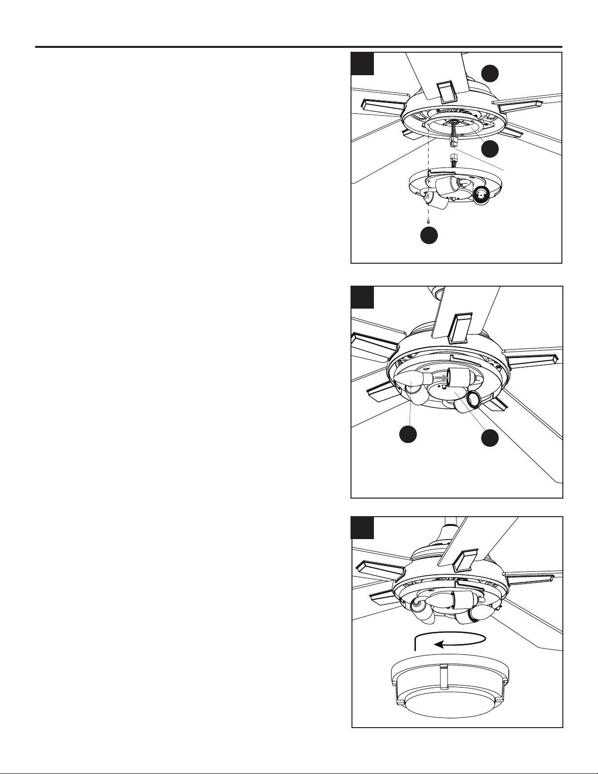
FINAL INSTALLATION
4. Remove one of the three tter plate screws (I) located
on the underside of the motor assembly (G) and loosen
the other two screws. Connect the 9-pin connector from
the tter plate (H) to the 9-pin connector from the light
kit (O). Align the two key slots in the light kit (O) with the
two previously loosened light pan screws (I). Place the
light kit (O) over the two screws and turn the light kit (O)
clockwise. Re-install the previously removed tter plate
screw (I), and tighten all three screws securely.
5. Install the bulbs (M) into the sockets of the light kit (O).
Important: Make sure you allow the bulbs (M) and light
kit (O) to cool before you replace the bulbs.
6. Attach the glass bowl (P) to the light kit (O) by twisting
the glass bowl (P) tightly in a clockwise direction until it
is secure. CAUTION: Avoid cross-threading the glass
during installation. Improper installation could cause
the glass bowl (P) to be dicult to remove or fall, which
could cause serious injury.
6
5
M
I
H
G
9-Pin
Connector
4
O
Loading ...
Loading ...
Loading ...