Loading ...
Loading ...
Loading ...
8
BOTTLE, KEG & BACK BAR COOLERS, GLASS & PLATE CHILLERS
OPERATIONS MANUAL
OPERATION WITH MECHANICAL THERMOSTAT
All cabinets must be given sufficient time to reach normal
operating temperature before placing any product inside.
Refrigerated bottle coolers are designed to maintain cabinet
temperature of 34°F to 38°F (1°C to 3°C) and approximately 3
hours of operation are required to reach this temperature.
NOTE: When loading product, a 2” air space under the
drain pan/evaporator cover is required for proper air flow
(see Figure 6).
REFRIGERATION SYSTEM AND ADJUSTMENT
The temperature control is accessible inside the cabinet, on the
back wall in front of the evaporator coil (see Figure 6, 6A & 6B).
If an adjustment is necessary to maintain the above temperature
range only, place a screwdriver into the thermostat slot and turn
clockwise for a colder cabinet temperature or counterclockwise
for a warmer cabinet temperature. Further adjustments out of
the factory design temperature range must be made by a quali-
fied refrigeration mechanic only.
EVAPORATOR ASSEMBLY
All models have an easily accessible, performance-rated, full
length, extra large, coated fin-type coil for extended life, with
a uniquely directed air flow distribution that keeps product at
uniformly constant temperatures (see Figure 6 & 6A).
IMPORTANT NOTE: All refrigerators have an automatic,
“off-cycle” defrost system, which means defrosting
occurs when the compressor is not operating during an
off-cycle. Do not set the temperature below 35°F (1.7°C)
because the evaporator will become blocked by ice, due
to shorter off-cycles. This can result in loss of product in
the cabinet and require manually defrosting your unit and
re-adjusting the temperature control.
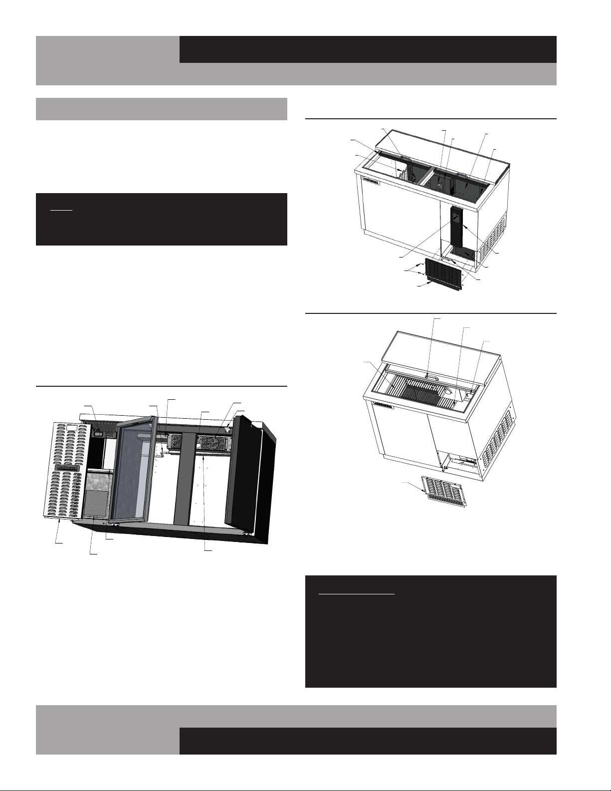
FIGURE 6: KC/BBC Component Location
FIGURE 6A: CBC Component Location
FIGURE 6B: CGC Component Location
LID
UPPER
SHELF
LOWER SHELF
GRILL
LOWER REAR
SHELF SUPPORT
FIGURE 6B: CGC Component Location
Loading ...
Loading ...
Loading ...