* All Pictures In This Manual Are For Illustrative Purposes Only. Actual Product May Vary.
© 2021 United States Stove Company, 227 Industrial Park Rd., South Pittsburg, TN 37380 Ph. 800-750-2723
THIS MANUAL IS SUBJECT TO CHANGE WITHOUT NOTICE.
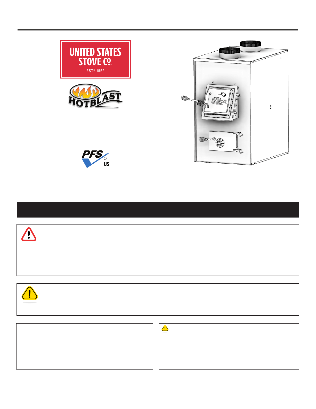
Owner’s Instruction and Operation Manual
U.S. Environmental Protection Agency
This heater is not certified for wood burning.
Use of any wood fuel is a violation of federal
regulations.
SAFETY NOTICE: If this heater is not properly installed, a house fire may result. For
your safety, follow the installation instructions. Never use make-shift compromises
during the installation of this heater. Contact local building or fire ocials about
permits, restrictions and installation requirements in your area. NEVER OPERATE
THIS PRODUCT WHILE UNATTENDED.
CAUTION! Please read this entire manual before you install or use your new room
heater. Failure to follow instructions may result in property damage, bodily injury, or
even death. Improper Installation Will Void Your Warranty!
Save These Instructions In A Safe Place For Future Reference.
CALIFORNIA PROPOSITION 65 WARNING:
This product can expose you to chemicals including carbon
monoxide, which is known to the State of California to cause
cancer, birth defects, and/or other reproductive harm. For
more information, go to www.P65warnings.ca.gov
851486Q - 0601K
Model Number:
COAL ONLY
1500
CERTIFIED TO UL 391-2006 (R2019)
DO NOT USE THIS FURNACE IN A MOBILE HOME OR TRAILER.
Report Number: F21-692
R
2
© 2021 United States Stove Company
NOTE: YOUR UNIT MUST BE INSTALLED BY A QUALIFIED
FURNACE INSTALLER.
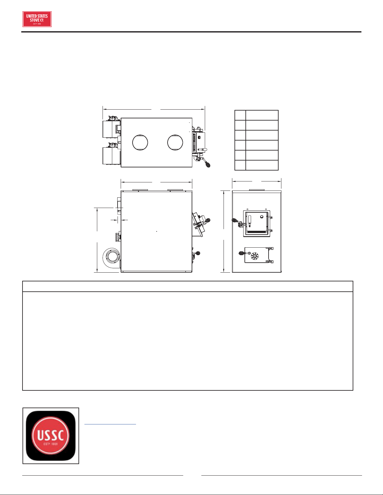
DIMENSIONS
For Customer Service, please call:
1-800-750-2723 Ext 5050 or;
Text to 423-301-5624 or;
Email us at:
customerservice@usstove.com
Note: Register your product online at
www.usstove.com or download the free
app today. This app is available only
on the App Store for iPhone and iPad.
Search US Stove. Save your receipt with
your records for any claims.
INTRODUCTION
A
C
D
E
F
B
A 49-1/8"
B 34"
C 24-1/16"
D 40"
E 2"
F 34"
FOR PARALLEL INSTALLATION WITH EXISTING FORCED AIR-GAS OR OIL FIRED FURNACE (U.S. ONLY) FOR
INSTALLATION AS A CENTRAL FURNACE.
CAUTIONS:
• HOT WHILE IN OPERATION. KEEP CHILDREN, CLOTHING AND FURNITURE AWAY. CONTACT MAY CAUSE
SKIN BURNS.
• DO NOT USE CHEMICALS OR FLUIDS TO IGNITE THE FIRE.
• DO NOT LEAVE THE STOVE UNATTENDED WHEN THE DOOR IS SLIGHTLY OPENED.
• DO NOT BURN GARBAGE, FLAMMABLE FLUID SUCH AS GASOLINE, NAPHTHA OR MOTOR OIL.
• DO NOT CONNECT TO ANY AIR DISTRIBUTION DUCT OR SYSTEM.
• ALWAYS CLOSE THE DOOR AFTER THE IGNITION.
• YOUR CHIMNEY MUST BE INSPECTED PRIOR TO THE INSTALLATION OF YOUR NEW COAL STOVE. IN
ADDITION, YOU SHOULD HAVE YOUR CHIMNEY INSPECTED FOR CREOSOTE DEPOSTS MONTHLY
DURING THE HEATING SEASON AND ANNUALLY INSPECTED AND CLEANED.
© 2021 United States Stove Company
3
INSTALLATION CHECKLIST
Your coal stove should be installed by a qualified installer only. An NFI qualified Installer can be found at www.
nficertified.org/public/find-an-nfi-pro/
CUSTOMER SERVICE
1-800-750-2723 ext 5050
Text to 423-301-5624
Email to: Customerservice@usstove.com
COMMISSIONING CHECKLIST
This Checklist is to be completed in full by the qualified person who installs this unit. Keep this page for future reference.
Failure to install and commission according to the manufacturer’s instructions and complete this checklist will
invalidate the warranty.
Please Print
Customer Name: Telephone Number:
Address:
Model:
Serial Number:
Installation Company Name: Phone Number:
Installation Technician’s Name: License Number:
DESCRIPTION OF WORK
Location of installed appliance: __________________________________________________________________________________
Venting System: New Venting System Yes No If yes, Brand ____________________________________________
If no, Date of inspection of existing venting system: _______________________________________________________________
COMMISSIONING
Confirm Hearth Pad Installation as per Installation Instructions ...................................................................................................
Confirm proper placement of internal parts ..........................................................................................................................................
Check soundness of door gasket and door seals .................................................................................................................................
Confirm clearances to combustibles as per installation instructions in this manual ..............................................................
Check the operations of the air controls .................................................................................................................................................
Confirm the venting system is secure and sealed ...............................................................................................................................
Confirm the stove starts and operates properly ..................................................................................................................................
Check to ensure a CO alarm is installed as per local building codes and is functional ............................................................
Explain the safe operation, proper fuel usage, cleaning, and routine maintenance requirements .......................................
Declaration of Completion: As the qualified person responsible for the work described above, I confirm that the appliance
as associated work has been installed as per manufacturer’s instructions and following any applicable building and
installation codes.
Signed: ______________________________________ Print Name: __________________________________Date: ______________
Home Owner: RETAIN THIS INFORMATION FOR FUTURE REFERENCE
4
© 2021 United States Stove Company
SAFETY
ATTENTION:
• FAILURE TO FOLLOW THE INFORMATION IN
THIS MANUAL WILL CAUSE A HAZARD THAT
COULD RESULT IN DEATH, SERIOUS BODILY
INJURY, AND/OR PROPERTY DAMAGE.
• CHECK YOUR LOCAL CODES. THE INSTALLATION
MUST COMPLY WITH THEIR RULINGS.
• ALWAYS CONNECT THIS FURNACE TO A
CHIMNEY AND VENT TO THE OUTSIDE. NEVER
VENT TO ANOTHER ROOM OR INSIDE A
BUILDING.
• DO NOT CONNECT THIS FURNACE TO AN
ALUMINUM TYPE B GAS VENT. THIS IS NOT
SAFE AND IS PROHIBITED BY THE NATIONAL
FIRE PROTECTION ASSOCIATION CODE. THIS
FURNACE REQUIRES A MASONRY OR LISTED
FACTORY BUILT CHIMNEY FOR RESIDENTIAL
TYPE OR BUILDING HEATING APPLIANCE
CHIMNEY. USE A 6" DIAMETER CHIMNEY OR
LARGER, THAT IS HIGH ENOUGH TO GIVE A
GOOD DRAFT.
• INSPECT CHIMNEY CONNECTOR AND
CHIMNEY BEFORE AND FREQUENTLY DURING
THE HEATING SEASON FOR ANY DEPOSIT
OF CREOSOTE OR SOOT WHICH MUST BE
REMOVED.
• PROVIDE AIR FOR COMBUSTION INTO THE
ROOM WHERE THE FURNACE IS LOCATED. IF
THE INTAKE IS NOT IN THE SAME ROOM, AIR
MUST HAVE FREE ACCESS TO THE ROOM.
• CAST IRON PARTS MUST BE "SEASONED" TO
AVOID CRACKING, BUILD ONLY SMALL FIRES
ON FIRST USE.
• TO PREVENT INJURY, DO NOT ALLOW ANYONE
TO USE THIS FURNACE WHO IS UNFAMILIAR
WITH THE CORRECT OPERATION OF THE
FURNACE.
CAUTION
GASES THAT ARE DRIVEN FROM FRESH COAL
MUST BE BURNED OR THEY WILL ACCUMULATE
AND EXPLODE. NEVER SMOTHER A FIRE WHEN
ADDING FRESH COAL.
DANGER: RISK OF FIRE OR EXPLOSION.
DO NOT BURN GARBAGE, GASOLINE, DRAIN OIL,
OR OTHER FLAMMABLE LIQUIDS.
WARNING: FIRE HAZARD.
• DO NOT OPERATE WITH FIRE DRAFT
EXCEEDING 0.06" W.C.
• DO NOT STORE FUELS, PAINTS, THINNERS,
FLAMMABLE LIQUIDS, OR OTHER HIGHLY
VOLATILE SUBSTANCES IN THE FURNACE
ROOM.
CAUTION!
CLEANOUT OF THE HEAT EXCHANGER, FLUE
PIPE, CHIMNEY, AND DRAFT INDUCER (IF USED),
IS ESPECIALLY IMPORTANT AT THE END OF THE
HEATING SEASON TO MINIMIZE CORROSION
DURING THE SUMMER MONTHS, CAUSED BY
ACCUMULATED ASH.
CAUTION!
INSPECT FLUE PIPES, FLUE PIPE JOINTS AND
FLUE PIPE SEALS REGULARLY TO ENSURE THAT
SMOKE AND FLUE GASES ARE NOT DRAWN INTO,
AND CIRCULATED BY, THE AIR CIRCULATION
SYSTEM.
SAFETY NOTICE:
IF THIS HEATER IS NOT PROPERLY INSTALLED,
A HOUSE FIRE MAY RESULT. FOR YOUR SAFETY,
FOLLOW THE INSTALLATION DIRECTIONS.
CONTACT LOCAL BUILDING OR FIRE OFFICIALS
ABOUT RESTRICTIONS AND INSTALLATION
INSPECTION REQUIREMENTS IN YOUR AREA.
IF NOT ALREADY INSTALLED, WE RECOMMEND
THAT SMOKE DETECTORS BE INSTALLED.
CAUTION:
HOT SURFACES! KEEP CHILDREN AWAY. DO NOT
TOUCH DURING OPERATION.
CREOSOTE ACCUMULATION CAUSES CHIMNEY
FIRES. YOU SHOULD CHECK (OR HAVE CHECKED BY
A QUALIFIED CHIMNEY SWEEP) YOUR CHIMNEY FOR
CREOSOTE DEPOSITS AT LEAST MONTHLY DURING
THE HEATING SEASON. ANY ACCUMULATIONS
SHOULD BE REMOVED. COMPLETE CHIMNEY
INSPECTIONS AND CLEANING SHOULD BE
CONDUCTED ANNUALLY; TYPICALLY, THIS TASK
SHOULD BE PERFORMED PRIOR TO EACH HEATING
SEASON. IF USING AN EXISTING CHIMNEY, IT MUST
BE INSPECTED PRIOR TO THE INSTALLATION OF
YOUR NEW WOOD STOVE.
© 2021 United States Stove Company
5
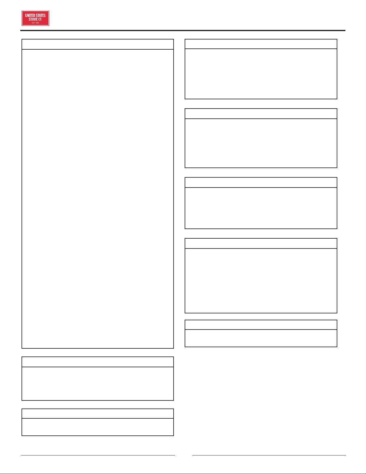
Your furnace requires the following items to be assembled
or installed by the service person:
• Feed Door Pull Handle
• Feed Door Locking Handle
• Blowers and Blower Controls
• Electrical Connections
1. Remove all parts from inside the furnace and inspect
for damage, including the firebrick as some breakage
could occur during shipment.
2. Assemble the feed door pull handle as shown. Install
thermostat assembly and cover (complete with
handle) as illustrated.
1
1
2
2
A A
B B
3. Align thermostat control knob with flat on thermostat
control shaft and press onto shaft.
SET SCREW
4. Attach feed door locking handle with screws and nuts
provided. Note: Slotted holes are for adjustment of
handle. Adjust handle until some pressure is required
to lock feed door during firing sequence.
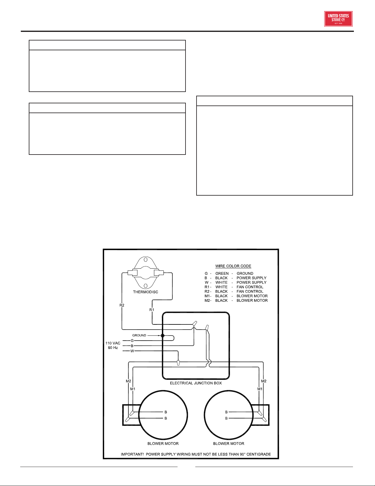
5. Install the thermodisc on rear of furnace cabinet
with the two screws provided. Mount the conduit
assembly from the junction box to the thermostat
bracket. Crimp the two female terminals to each
of the wire leads. Plug the wires to the thermodisc.
NOTE: It does not matter which of the two wires
plugs to which terminal on the thermodisc.
6. Remove blowers from cartons. Remove junction box
cover. Attach clip nuts as shown. Install blowers and
gaskets with 1/4"-20 x 3/4" bolts as shown.
THERMODISC
THERMODISC
COVER
4” ELECTRICAL
JUNCTION BOX
BLOWERS
BLOWERS GASKET
CLIP NUTS
(Not used in the upper center hole.)
7. Wire right side blower first (See wiring diagram) and
replace cover on junction box on blower.
8. Wire left blower same as above and replace cover.
9. Check operation of shaker grates with grate handle
before operating furnace.
ASSEMBLY & INSTALLATION
6
© 2021 United States Stove Company
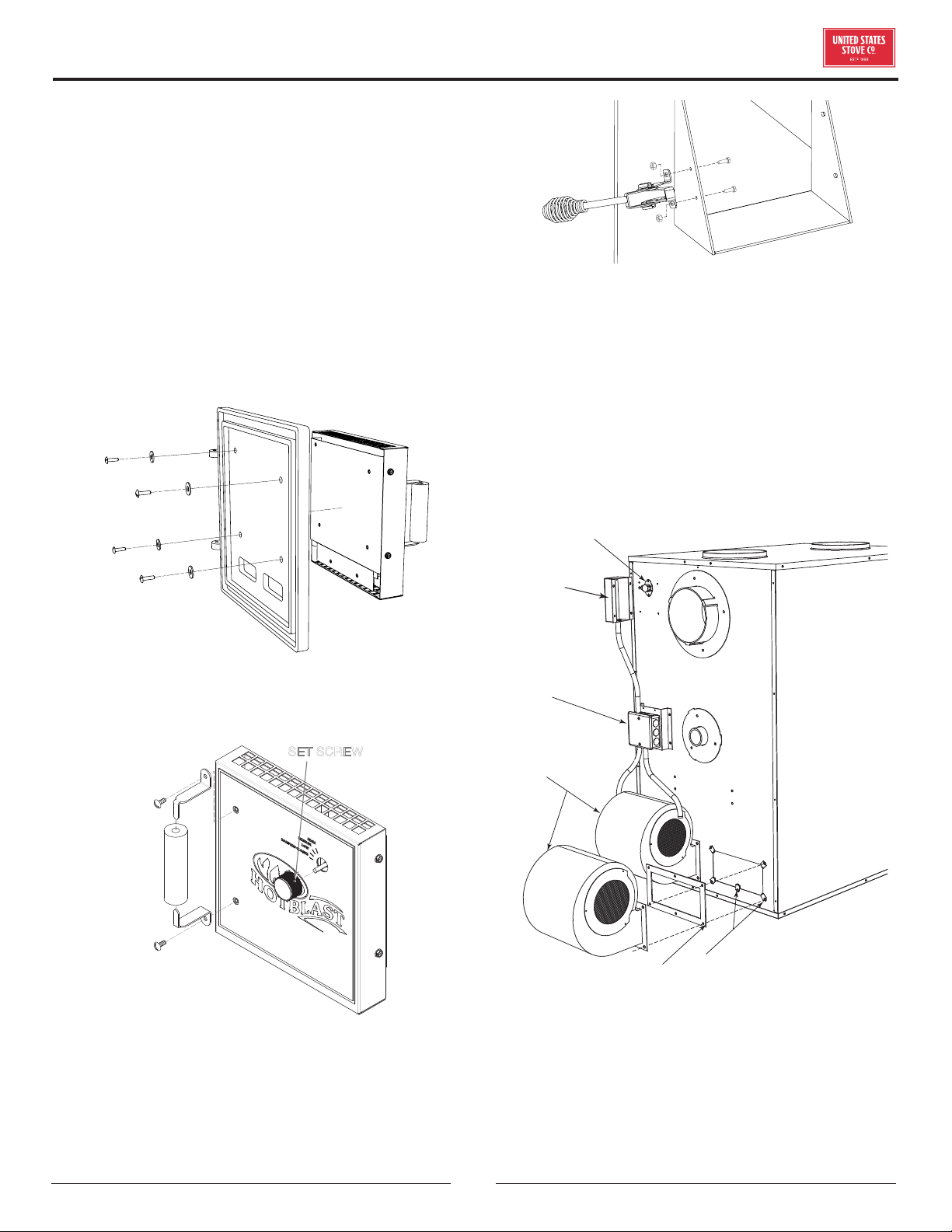
OPTIONAL EQUIPMENT
11DIKL DRAFT INDUCER KIT W/ LIMIT
SWITCH
This optional kit allows your furnace to be thermostatically
controlled and gives the option to change the on/o times
of the distribution blower(s).
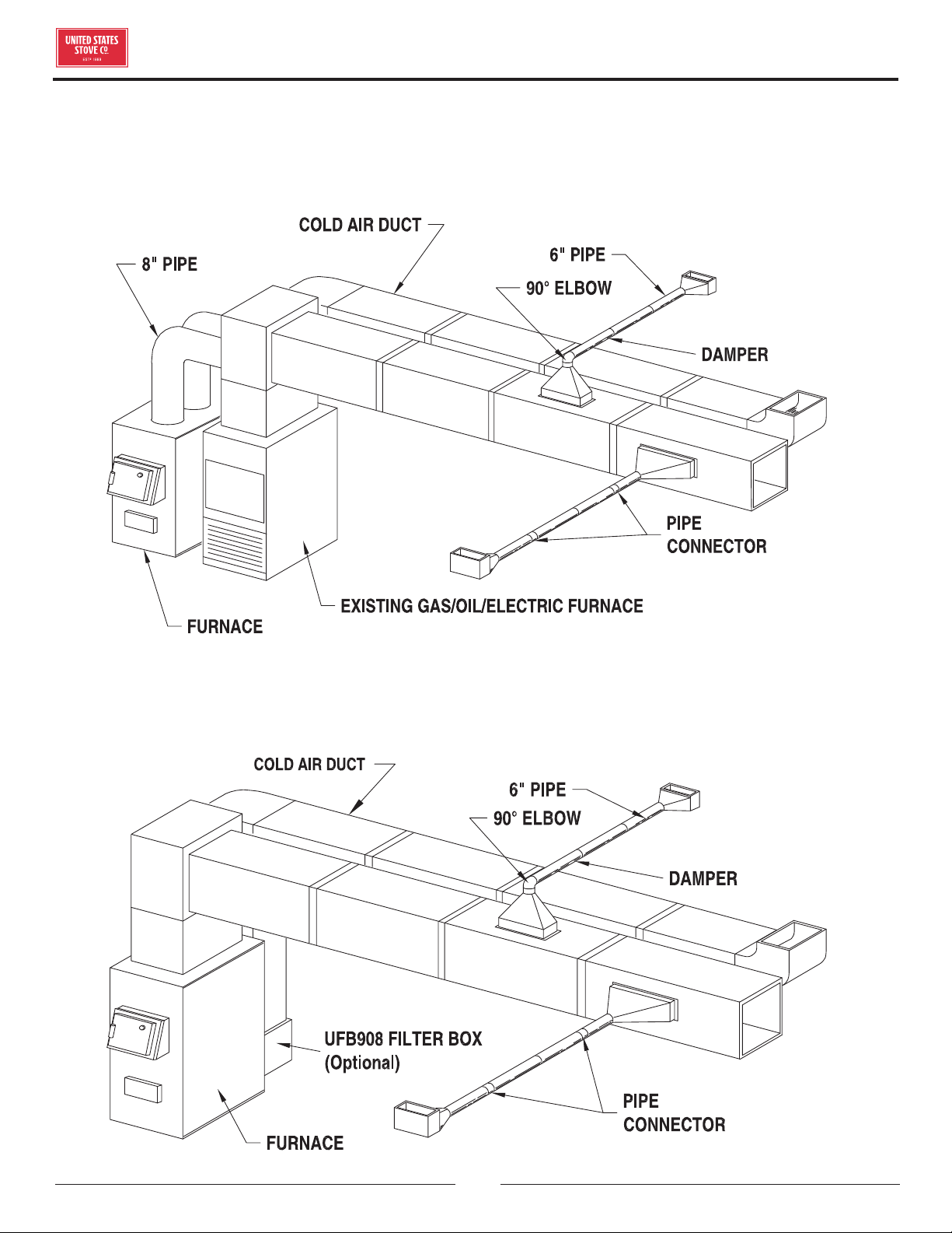
UFB908 UNIVERSAL FILTER BOX
When installing ANY warm air furnace, proper installation
is the key and required for getting the most eciency and
longest life out of your unit. Failure to install your furnace
as outlined from the manufacturer, often will result
in inadequate heating and problems associated with
drafting. U. S. Stove Co. oers the UFB908, a universal
filter box that mounts to the rear of the unit that your
return air duct work will attach to. It uses a standard 16
x 20 x 1 filter (NOT INCLUDED) to reduce the amount of
dust particles from being transferred thru you duct work
system.
DR6 BAROMETRIC DAMPER REGULATOR
In the unlikely event that your furnace “overfires”
(a condition evidenced by elbows, stove pipes, and
connectors glowing red in appearance or otherwise
discoloring), then your installation is subject to excessive
draft created by either a chimney too tall or too great in
diameter in conjunction with its height, or some other
factor of an indeterminate cause. In this event, you should
install a barometric draft regulator. Such installation
will preclude any over-firing and/or any hazardous
consequences of potential overfiring. Barometric draft
regulators are generally available where you purchased
your stove or may be ordered directly from United States
Stove Company at a nominal charge.
© 2021 United States Stove Company
7
Your Furnace is designed to be installed in a parallel
air flow arrangement with a gas or oil-fired forced air
upflow-type central furnace, or it may be installed as a
central furnace.
HOW THE FURNACE FUNCTIONS
This furnace is designed to be a supplemental or
central heating source for your home. This solid fuel
furnace may be installed in conjunction with a properly
operating central furnace that is listed or certified in
accordance with nationally recognized safety standards
and equipped with the required controls and other safety
features and which has been installed in accordance with
appropriate standards of the National Fire Protection
Association with installation clearances specified in the
furnace nameplate marking. The installation must be
accomplished by a qualified agency (one who is engaged
in, and is responsible for, or is thoroughly familiar with
the installation and operation of the gas, oil, and solid
fuel burning heating appliances, who is experienced
in such work, familiar with all the requirements of the
authority having jurisdiction.) The installation shall be
in strict accordance with the manufacturer's installation
instructions furnished with the solid fuel furnace. The
chimney connector of the furnace is to be installed to
provide clearances to combustible material not less than
specified in the individual classifications and marked on
the furnace. The chimney connector must be connected
to a chimney suitable for use with residential type or
building heating appliances which burn solid fuel. The
Furnace is designed to operate in either parallel or series
air flow arrangement with the central furnace or as a
central furnace.
CENTRAL FURNACE INSTALLATION
As a central furnace, the unit functions independently
of any other system. The blower will come on when the
plenum temperature reaches the setting on the blower
control.
PARALLEL INSTALLATION (U.S. ONLY)
The design is such that when the blower comes on, the
blower on the central system also comes on. The blower
will only come on when the temperature in the plenum
has reached the setting on the blower control. This is to
ensure that there is sucient warm air in the system to
make it ecient for the unit to operate. When the central
system thermostat calls for heat, the central system will
operate by the burner igniting and the blower coming on. It
is possible that both systems will operate simultaneously.
It is recommended that for the most ecient use of this
furnace, that it be fired as much as possible in order to
reduce the demand on your existing central heating
system. This unit has an optional forced draft kit that
operates from a wall thermostat. When the temperature
falls below the setting on the wall thermostat, the forced
draft will come on (U.S. Stove Option 11/DIKL) The warm
air supply outlet of the this furnace shall not be connected
to the cold air return of the central furnace, because the
possibility exists of components of the central furnace
overheating and causing the central furnace to operate
other than is intended.
SERIES INSTALLATION
This type of installation uses only the blowers of the
existing central furnace. The solid fuel fan/limit control
must also control the functions of the existing furnace. All
electrical power must come from a single branch circuit.
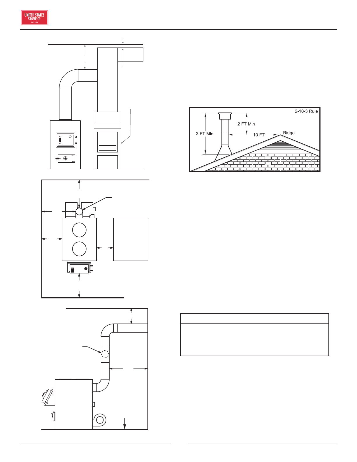
LOCATING THE FURNACE
1. The furnace should be located in the same room
as the central system and as close as possible, but
not closer than 9". There should be no wall between
the furnace and the warm air outlet duct that is
connected directly to the warm air outlet plenum of
the central furnace.
2. Place the furnace on a noncombustible floor.
3. Ensure you have the clearances shown in this
manual from the furnace and the connector pipe
to combustible surfaces. If you have a solid brick
or stone wall behind your furnace, you can place
the furnace as close as you wish to the wall. If the
wall is only faced with brick or stone, treat it as a
combustible wall.
A Unit to Sidewall 12" (305mm)
B Unit to Backwall 30" (760mm)
C
Front of Unit to
Combustible
48" (1.22m)
D
Chimney Pipe to
Sidewall
21" (530mm)
E
Chimney Pipe to
Backwall
18" (460mm)
F
Plenum to
Combustibles
6" (150mm)
INSTALLATION
8
© 2021 United States Stove Company
2" MIN.
AIRSPACE
REQUIRED
BY CODE
CENTRAL
FURNACE
F
PLENUM
TO
CEILING
18"
18"
6" BAROMETRIC
DRAFT REGULATOR
NON-COMBUSTIBLE
FLOOR
12"
9"
48"
18"
CENTRAL
FURNACE
6" CHIMNEY
21"
18"
18"
6" BAROMETRIC
DRAFT REGULATOR
NON-COMBUSTIBLE
FLOOR
12"
9"
48"
18"
CENTRAL
FURNACE
6" CHIMNEY
21"
LISTED FACTORY BUILT CHIMNEY
Carefully follow chimney manufacturer's instructions.
Use only a Listed Residential Type or Building Heating
Appliance Chimney. If your chimney starts at the ceiling,
you will need enough 6" pipe to reach the ceiling. The top
of the chimney must be at least 3 feet above the roof and
be at least 2 feet higher than any point of the roof within
10 feet.
IMPORTANCE OF PROPER DRAFT
Draft is the force which moves air from the appliance
up through the chimney. The amount of draft in your
chimney depends on the length of the chimney, local
geography, nearby obstructions and other factors. Too
much draft may cause excessive temperatures in the
appliance. Inadequate draft may cause backpung into
the room and ‘plugging’ of the chimney. Inadequate draft
will cause the appliance to leak smoke into the room
through appliance and chimney connector joints. An
uncontrollable burn or excessive temperature indicates
excessive draft. Take into account the chimney’s location
to ensure it is not too close to neighbors or in a valley
which may cause unhealthy or nuisance conditions.
MASONRY CHIMNEY
CAUTION:
BE SURE THAT IF A MASONRY CHIMNEY IS
USED, IT IS SAFELY CONSTRUCTED AND IN GOOD
REPAIR. HAVE THE CHIMNEY INSPECTED BY THE
FIRE DEPARTMENT OR AN INSPECTOR.
Ensure that a masonry chimney meets the minimum
standards of the National Fire Protection Association
(NFPA) by having it inspected by a professional. Make
sure there are no cracks, loose mortar or other signs of
deterioration and blockage. Have the chimney cleaned
before the furnace is installed and operated. When
connecting the furnace through a combustible wall to
a masonry chimney, special methods are needed as
INSTALLATION
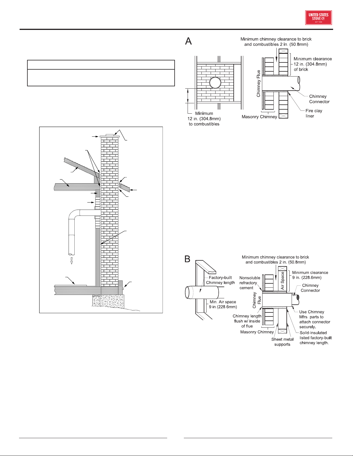
© 2021 United States Stove Company
9
explained in the “Combustible Wall Chimney Connector
Pass-Throughs” Section.
WARNING:
DO NOT CONNECT THIS FURNACE TO A CHIMNEY
FLUE SERVING ANOTHER APPLIANCE.
The chimney used for a furnace must not be used to
ventilate the cellar or basement. If there is a cleanout
opening at the base of the chimney, close it tightly.
Sheathing
Airtight
Cleanout
Door
Floor
Protector
Thimble
12” of Brick
Combustible Wall
1” Clearance
with Firestop
Rafter
Concrete Cap
Flashing
To Stove
1” Clearance
Eave
Flashing
Fireclay Flue
Liner With
Airspace
COMBUSTIBLE WALL CHIMNEY
CONNECTOR PASSTHROUGHS
Method A - 12” (304.8 mm) Clearance to Combustible
Wall Member: Using a minimum thickness 3.5” (89 mm)
brick and a 5/8” (15.9 mm) minimum wall thickness clay
liner, construct a wall pass-through. The clay liner must
conform to ASTM C315 (Standard Specification for
Clay Fire Linings) or its equivalent. Keep a minimum of
12” (304.8 mm) of brick masonry between the clay liner
and wall combustibles. The clay liner shall run from the
brick masonry outer surface to the inner surface of the
chimney flue liner but not past the inner surface. Firmly
grout or cement the clay liner in place to the chimney flue
liner.
Method B - 9” (228.6 mm) Clearance to Combustible
Wall Member: Using a 6” (152.4 mm) inside diameter,
listed, factory-built Solid-Pak chimney section with
insulation of 1” (25.4 mm) or more, build a wall pass-
through with a minimum 9” (228.6 mm) air space
between the outer wall of the chimney length and wall
combustibles. Use sheet metal supports fastened
securely to wall surfaces on all sides, to maintain the
9” (228.6 mm) air space. When fastening supports to
chimney length, do not penetrate the chimney liner (the
inside wall of the Solid-Pak chimney). The inner end of
the Solid-Pak chimney section shall be flush with the
inside of the masonry chimney flue, and sealed with a
non-water soluble refractory cement. Use this cement to
also seal to the brick masonry penetration.
Method C - 6” (152.4 mm) Clearance to Combustible
Wall Member: Starting with a minimum 24 gauge (.024”
[.61 mm]) 6” (152.4 mm) metal chimney connector, and
a minimum 24 gauge ventilated wall thimble which has
two air channels of 1” (25.4 mm) each, construct a wall
pass-through. There shall be a minimum 6” (152.4) mm
separation area containing fiberglass insulation, from the
outer surface of the wall thimble to wall combustibles.
Support the wall thimble, and cover its opening with a
24-gauge minimum sheet metal support. Maintain the
INSTALLATION
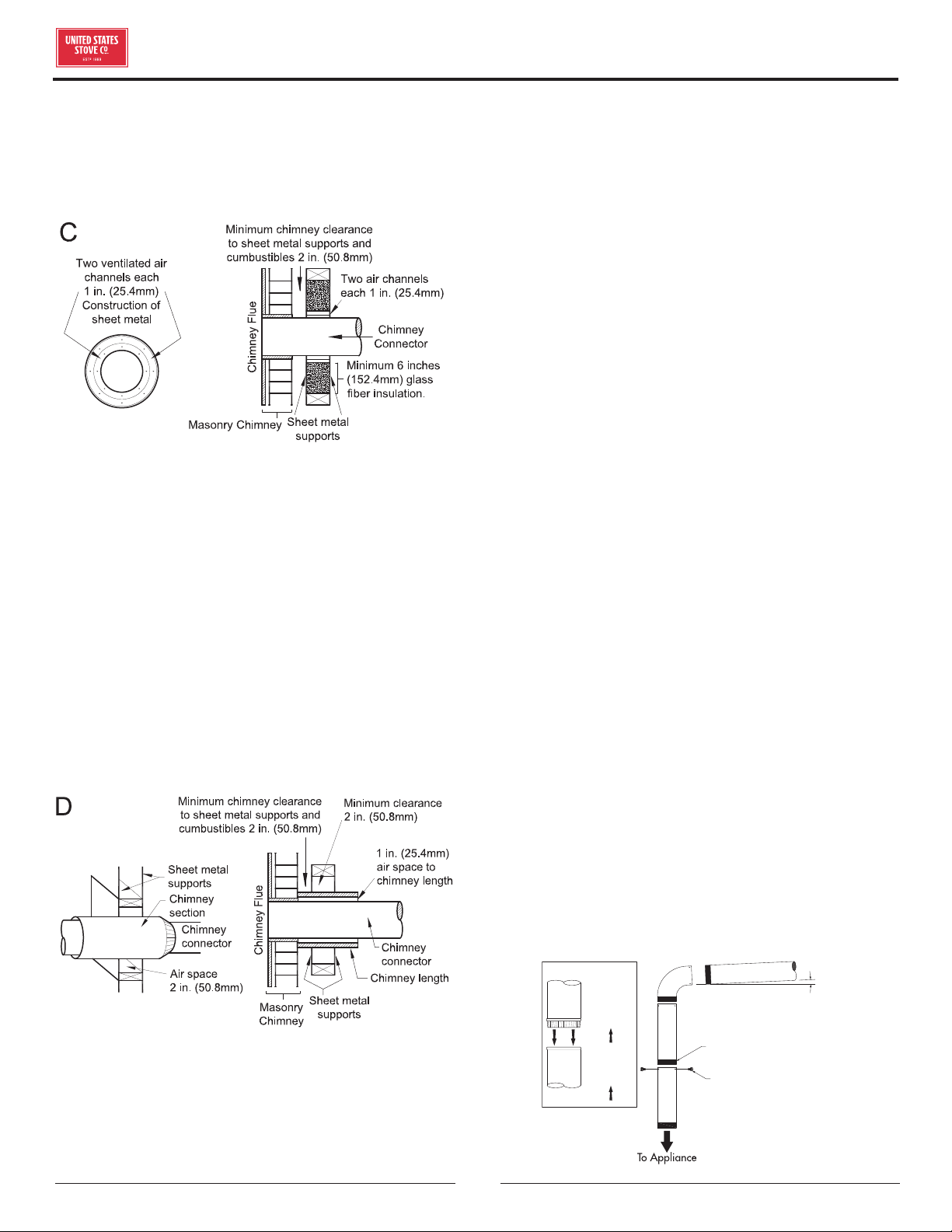
10
© 2021 United States Stove Company
INSTALLATION
6” (152.4 mm) space. There should also be a support
sized to fit and hold the metal chimney connector. See
that the supports are fastened securely to wall surfaces
on all sides. Make sure fasteners used to secure the metal
chimney connector do not penetrate chimney flue liner.
Method D - 2” (50.8 mm) Clearance to Combustible
Wall Member: Start with a solid-pak listed factory
built chimney section at least 12” (304 mm) long, with
insulation of 1” (25.4 mm) or more, and an inside diameter
of 8” (2 inches [51 mm] larger than the 6” [152.4 mm]
chimney connector). Use this as a pass-through for a
minimum 24-gauge single wall steel chimney connector.
Keep solid-pak section concentric with and spaced 1”
(25.4 mm) o the chimney connector by way of sheet
metal support plates at both ends of chimney section.
Cover opening with and support chimney section on both
sides with 24 gauge minimum sheet metal supports. See
that the supports are fastened securely to wall surfaces
on all sides. Make sure fasteners used to secure chimney
flue do not penetrate flue liner.
NOTES: Connectors to a masonry chimney, excepting
method B, shall extend in one continuous section through
the wall pass-through system and the chimney wall, to
but not past the inner flue liner face. A chimney connector
shall not pass through an attic or roof space, closet or
similar concealed space, or a floor, or ceiling.
CHIMNEY CONNECTOR
• Your chimney connector and chimney must have the
same diameter as the furnace outlet. If this is not the
case, we recommend you contact your dealer in order
to ensure there will be no problem with the draft.
• The furnace pipe must be made of aluminized or cold
roll steel with a minimum thickness of 0.021” or 0.53
mm. It is strictly forbidden to use galvanized steel.
• Your connector should be assembled in such a way that
the male section (crimped end) of the pipe faces down.
Attach each of the sections to one another with three
equidistant metal screws. Seal the joints with furnace
cement.
• The pipe must be short and straight. All sections
installed horizontally must slope at least 1/4 inch
per foot, with the upper end of the section toward
the chimney. Any installation with a horizontal run
of furnace pipe must conform to NFPA 211. You may
contact NFPA (National Fire Protection Association)
and request the latest edition of the NFPA Standard
211.
• To ensure a good draft, the total length of the furnace
pipe should never exceed 8’ to 10’ (2.4m to 3.04 m).
(Except for cases of vertical installation, cathedral-roof
style where the smoke exhaust system can be much
longer and connected without problem to the chimney
at the ceiling of the room).
• There should never be more than two 90 degrees
elbows in the smoke exhaust system.
• Installation of a “barometric draft stabilizer” (fireplace
register) on a smoke exhaust system is prohibited.
• Do not use with a flue damper. With a controlled
combustion coal furnaces the draft is regulated upon
intake of the combustion air in the furnace and not at
the exhaust.
3 screws
Flow
Direction
of Flue
Gases
Install
crimped
end
towards
stove.
Male Part Downwards
1/4” slope per foot
© 2021 United States Stove Company
11
• The chimney connector must not extend into the
chimney flue.
RIGHT WRONG WRONG
• The chimney connector may include a section for a
barometric draft regulator between the furnace and
the chimney. The barometric draft regulator must be
installed in the same room (same pressure zone) as the
furnace.
6" BAROMETRIC
DRAFT REGULATOR
NON COMBUSTIBLE
INSTALLATION PER
NFPA 211
MEASURE FLUE
DRAFT HERE
• Install the barometric draft regulator strictly in
accordance with the instructions that are provided
with the barometric draft regulator.
This is a furnace, not a free standing stove. You must
direct heated air from 8" outlets away from the furnace,
or it will not function properly.
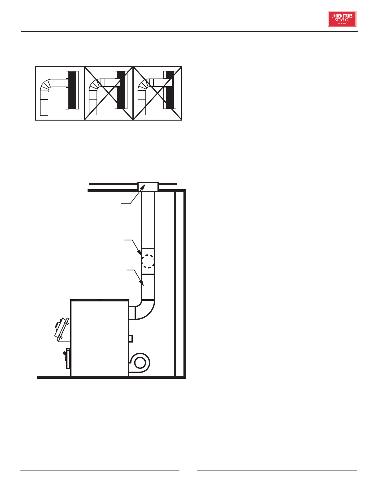
1. This installation must be done by a qualified heating
equipment installer.
2. Installation for Supplemental Heat Application to
Existing Central System.
a. Place Coal Burning Furnace so that the chimney
connector will be as short as practical and avoiding
unnecessary sharp turns in the smoke pipe connector
and the installation of devices that would create
excessive resistance to the flow of flue gases.
b. Locate the Coal Burning Furnace as close as practical
to the existing central hot air heating system,
maintaining clearances as stated on the label on the
fuel door.
c. Clearance from combustible materials must comply
with those stated on the label on the side of the
unit. Refer to the clearance table in the front of this
manual. The installation must be made only on a
noncombustible floor.
d. Install the smoke pipe connector to the chimney
with 26-gauge pipe and elbows (to be purchased
separately), maintaining the proper clearances for the
specific model. Seal the smoke pipe in the chimney
with furnace cement. (The chimney connector shall
be securely supported, and joints fastened with sheet
metal screws or rivets.)
e. Install 8" diameter heat pipe to plenum of the central
hot air furnace. Use 26-gauge pipe and connectors (to
be purchased separately). If central air conditioning
is installed in the plenum, install heat pipe above the
air conditioning unit. Secure heat pipe connection
with supports and sheet metal screws.
f. Connect electrical supply in the electrical junction
box that is mounted on the back of the Furnace. See
Wiring Diagram. Remove the cover from electrical
junction box and connect power supply wires to wires
designated, using wire nuts. The power cord supplied
may be used for installation, if permitted by local
codes and regulations. If the power cord supplied
cannot be used, the power supply wiring must be
90 degrees centigrade in a metal cable and should
be completed by a qualified installer complying with
NFPA Standard No. 70 and local codes.
INSTALLATION
12
© 2021 United States Stove Company
CENTRAL INSTALLATION
ADD-ON INSTALLATION
INSTALLATION
METHODS OF INSTALLATION.
© 2021 United States Stove Company
13
INSTALLATION
INSTALLATION A
TO EXISTING
DUCT WORK
WARM AIR
EXISTING FURNACE
SOLID FUEL FURNACE
FILTER BOX
COLD AIR
RETURN
INSTALLATION B
PLENUM
COLLECTOR
BOX
TO EXISTING
DUCT WORK
WARM AIR
EXISTING FURNACE
SOLID FUEL FURNACE
FILTER BOX
COLD AIR
RETURN
INSTALLATION C
PLENUM TOP
(OPTIONAL)
TO EXISTING
DUCT WORK
WARM AIR
EXISTING FURNACE
SOLID FUEL FURNACE
FILTER BOX
COLD AIR
RETURN
INSTALLATION D
FURNACE
PLENUM
EXISTING
FURNACE
SOLID
FUEL
FURNACE
ANTI-
BACKDRAFT
FLAPPER
COLD AIR
RETURN
2” min.
CLEARANCE
14
© 2021 United States Stove Company
INSTALLATION E
FURNACE
PLENUM
BAFFLE
EXISTING
FURNACE
SOLID
FUEL
FURNACE
COLD AIR
RETURN
2” min.
CLEARANCE
INSTALLATION F
FURNACE
PLENUM
EXISTING
FURNACE
SOLID
FUEL
FURNACE
COLD AIR
RETURN
2” min.
CLEARANCE
INSTALLATION G
SOLID
FUEL
FURNACE
2” min.
CLEARANCE
COLD AIR
RETURN TO
FILTER BOX
INSTALLATION H
SOLID
FUEL
FURNACE
EXISTING OIL,
ELECTRIC,
OR GAS
FURNACE
TOP VIEW
SOLID
FUEL
FURNACE
2” min.
CLEARANCE
EXISTING OIL,
ELECTRIC,
OR GAS
FURNACE
FRONT VIEW
INSTALLATION
© 2021 United States Stove Company
15
OPERATION
CAUTION
• DO NOT OPERATE WITH THE FEED AND/OR
ASH DOOR OPEN. THIS FURNACE IS DESIGNED
FOR THERMOSTATIC OPERATION. OPERATION
WITH ANY OF THESE DOORS OPEN WILL
OVERHEAT AND DAMAGE THE FURNACE.
• KEEP THE ASH PIT SECTION FREE OF EXCESS
ASHES. DO NOT ALLOW ASHES TO STACK
HIGHER THAN THE SIDES OF THE ASH PAN.
• KEEP THE FEED AND ASH DOORS CLOSED
AT ALL TIMES EXCEPT WHILE TENDING THE
FURNACE.
DO NOT OPERATE WITH FUEL LOADING OR ASH
REMOVAL DOORS OPEN.
CAUTION
NEVER USE GASOLINE, GASOLINE-TYPE LANTERN
FUEL, KEROSENE, CHARCOAL LIGHTER FLUID, OR
FLAMMABLE LIQUIDS TO START OR "FRESHEN
UP" A FIRE IN THE FURNACE.
WARNING
NEVER STORE FLAMMABLE LIQUIDS, ESPECIALLY
GASOLINE, IN THE VICINITY OF THE FURNACE.
The top down method of fire building is recommended for
this appliance. DO NOT BURN:
1. Garbage;
2. Lawn clippings or yard waste;
3. Materials containing rubber, including tires;
4. Materials containing plastic;
5. Waste petroleum products, paints or paint thinners,
or asphalt products;
6. Materials containing asbestos;
7. Construction or demolition debris;
8. Railroad ties or pressure-treated wood;
9. Manure or animal remains;
10. Saltwater driftwood or other previously saltwater
saturated materials;
Burning these materials may result in release of toxic
fumes or render the heater ineective and cause smoke.
POWER FAILURE
After loss of power remove the filter if provided and do
not expect to keep home at normal temperatures.
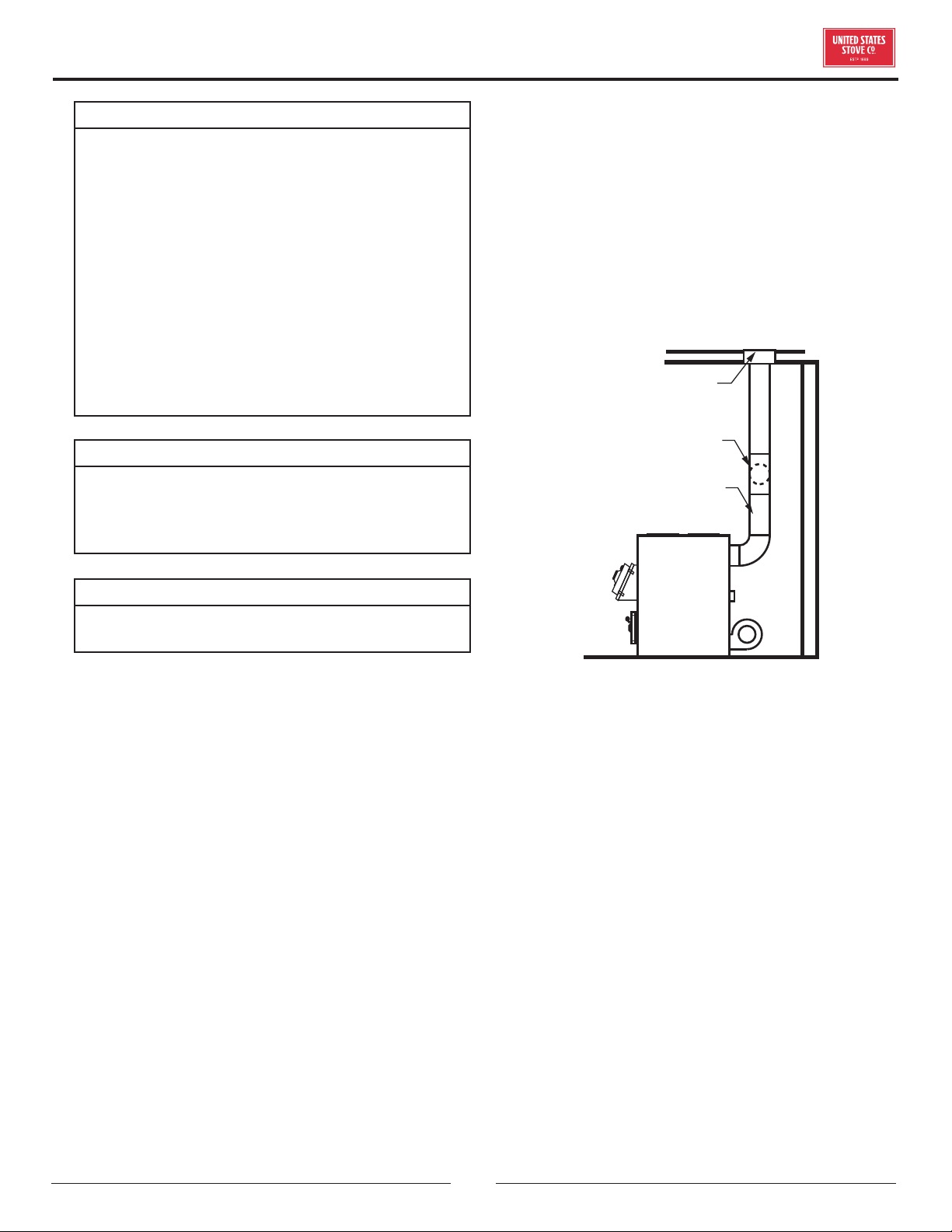
ADJUSTING THE BAROMETRIC DRAFT
REGULATOR
1. Drill a hole in the chimney connector within 18" of the
flue collar below the barometric draft regulator just
large enough for the tube of the manometer.
2. Build a fire after all chimney connections have been
made.
3. Use a manometer to measure the draft in the flue.
4. Adjust the Barometric Draft Regulator to obtain a
draft of 0.05 - 0.06" W.C. under stable fire conditions.
6" BAROMETRIC
DRAFT REGULATOR
NON COMBUSTIBLE
INSTALLATION PER
NFPA 211
MEASURE FLUE
DRAFT HERE
TAMPER WARNING
This coal heater has a manufacturer-set minimum low
burn rate that must not be altered.
VISIBLE SMOKE
The amount of visible smoke being produced can be
an eective method of determining how eciently the
combustion process is taking place at the given settings.
Visible smoke consist of unburned fuel and moisture
leaving your stove. Learn to adjust the air settings of your
specific unit to produce the smallest amount of visible
smoke.
OVER FIRING
Attempts to achieve heat output rates that exceed heater
design specifications can result in permanent damage to
the heater.
ASH REMOVAL & DISPOSAL
Whenever ashes get 3 to 4 inches deep in your firebox or
ash pan, and when the fire has burned down and cooled,
remove excess ashes. Leave an ash bed approximately
1 inch deep on the firebox bottom to help maintain a
16
© 2021 United States Stove Company
OPERATION
hot charcoal bed. Ashes should be placed in a metal
container with a tight-fitting lid. The closed container of
ashes should be placed on a noncombustible floor or on
the ground, away from all combustible materials, pending
final disposal. The ashes should be retained in the closed
container until all cinders have thoroughly cooled.
SMOKE & CO MONITORS
CO is a poisonous gas when exposed to elevated
concentrations for extended periods of time. While
the modern combustion systems in heaters drastically
reduce the amount of CO emitted out the chimney,
exposure to the gases in closed or confined areas can be
dangerous. Make sure your stove gaskets and chimney
joints are in good working order and sealing properly to
ensure unintended exposure. It is recommended that
you use both smoke and CO monitors in areas having the
potential to generate CO.
GASKETS
It is recommended that you change the door gasket
(which makes your stove door air tight) once a year,
in order to ensure good control over the combustion,
maximum eciency and security. To change the door
gasket, simply remove the damaged one. Carefully clean
the available gasket groove, apply a high temperature
silicone sold for this purpose, and install the new gasket.
You may light up your stove again approximately 24
hours after having completed this operation. This unit’s
ash door uses a 5/8" diameter rope gasket. This unit's
feed door uses a 1/2" diameter rope gasket.
SERVICE HINTS
Do not expect a furnace to draw. It is the chimney that
creates the draft. Smoke spillage into the house or
excessive build-up of water or creosote in the chimney
are warnings that the chimney is not functioning properly.
Correct the problem before using furnace. Possible
causes are:
1. The connector pipe may be pushed into the chimney
too far, stopping the draft.
2. Do not connect two furnaces or a stove and furnace
into the same chimney flue.
3. The chimney used for a furnace must not be used to
ventilate the cellar or basement. If there is a cleanout
opening at the base of the chimney, it must be closed
tightly.
4. If the chimney is operating too cool, water will
condense in the chimney and run back into the
furnace. Creosote formation will be rapid and may
block the chimney. Operate the furnace at a high
enough fire to keep the chimney warm, preventing
this condensation.
5. If the fire burns well, but sometimes smokes or burns
slowly, it may be caused by the chimney top being
lower than another part of the house or a nearby tree.
The wind blowing over a house or a tree, falls on top
of the chimney like water over a dam, beating down
the smoke. The top of the chimney should be at least
3 feet above the roof and be at least 2 feet higher
than any point of the roof within 10 feet.
CREOSOTE & SOOT FORMATION & NEED
FOR REMOVAL
When coal is burned, the products of combustion combine
with moisture to form a soot residue which accumulates
on the flue lining. When ignited, this soot makes an
extremely hot fire. The chimney should be inspected
at least twice monthly during the heating season to
determine if a creosote or soot build up has occurred. If
creosote or soot has accumulated, it should be removed
to reduce the risk of a chimney fire. Chimney fires burn
very hot. If the chimney catches fire, immediately call the
fire department, then reduce the fire by closing the inlet
air control. Pour a large quantity of coarse salt, baking
soda or cool ashes on top of the fire in the firebox.
CREOSOTE ACCUMULATION CAUSES CHIMNEY
FIRES. YOU SHOULD CHECK (OR HAVE CHECKED BY
A QUALIFIED CHIMNEY SWEEP) YOUR CHIMNEY FOR
CREOSOTE DEPOSITS AT LEAST MONTHLY DURING
THE HEATING SEASON. ANY ACCUMULATIONS
SHOULD BE REMOVED. COMPLETE CHIMNEY
INSPECTIONS AND CLEANING SHOULD BE
CONDUCTED ANNUALLY; TYPICALLY, THIS TASK
SHOULD BE PERFORMED PRIOR TO EACH HEATING
SEASON. IF USING AN EXISTING CHIMNEY, IT MUST
BE INSPECTED PRIOR TO THE INSTALLATION OF
YOUR NEW WOOD STOVE.
CAUTION
A CHIMNEY FIRE MAY CAUSE IGNITION OF WALL
STUDS OR RAFTERS WHICH YOU THOUGHT WERE
A SAFE DISTANCE FROM THE CHIMNEY. IF YOU
HAVE A CHIMNEY FIRE, HAVE YOUR CHIMNEY
INSPECTED BY A QUALIFIED PERSON BEFORE
USING AGAIN.
© 2021 United States Stove Company
17
OPERATION
ATTENTION:
A DRAFT READING OF .05 TO .06 W.C. IS
SUGGESTED FOR PROPER BURNING OF THIS UNIT
WHEN USING BITUMINOUS COAL AS FUEL. WHEN
USING ANTHRACITE COAL, THIS DRAFT READING
IS A MINIMUM READING.
ATTENTION:
THIS HEATER NEEDS PERIODIC INSPECTION
AND REPAIR FOR PROPER OPERATION. IT IS
AGAINST FEDERAL REGULATIONS TO OPERATE
THIS HEATER IN A MANNER INCONSISTENT WITH
OPERATING INSTRUCTIONS IN THIS MANUAL.
CARING FOR PAINTED PARTS
This furnace has a painted outside jacket, which is
durable, but it will not stand rough handling or abuse.
When installing your furnace, use care in handling. Clean
with soap and warm water when furnace in not hot. DO
NOT use any acids or scouring soap, as these wear and
dull the finish. DISCOLORATION WILL OCCUR IF THE
FURNACE IS OVERHEATED. FOLLOW OPERATING
INSTRUCTIONS CAREFULLY.
CAUTION:
THE SPECIAL PAINTS USED ON YOUR FURNACE
MAY GIVE OFF SOME SMOKE WHILE THEY
ARE CURING DURING FIRST FEW FIRES., BUILD
SMALL FIRES AT FIRST. THE METAL USED IN
CONSTRUCTION OF THE FURNACE AND DUCT
WORK HAS A LIGHT COATING OF OIL. THIS
COULD GIVE OFF SMOKE AND/OR ODOR FROM
REGISTERS WHEN FURNACE IS USED FOR THE
FIRST TIME. THIS SHOULD DISAPPEAR AFTER A
SHORT PERIOD OF TIME. ONCE THIS BURN-OFF
HAS OCCURRED, IT SHOULD NOT REOCCUR.
WIRING DIAGRAM
18
© 2021 United States Stove Company
TROUBLE SHOOTING
Problem: Solution
Smoke pus from
furnace
Check chimney draft. Check for blocked chimney or flue pipe. Use mirror to check chimney
clearance.
Check ash pit — if it is too full, empty.
Make sure furnace room is not too airtight.
Make sure all of chimney mortar connections are airtight.
Check ash drawer. Make sure it’s airtight.
Check chimney for possible down-draft caused by taller surrounding trees or objects. Correct
with proper chimney vent cap.
Check the possibility of a cold chimney forcing cool gases backward. Remedied by properly
insulating chimney with non-combustible liner — non-combustible insulation.
Fuel may be too green.
Make sure no other fuel burning devices are connected to the chimney impairing the draft.
Check chimney draft, it should be .06 inches of water column. This service is provided by a
certified chimney sweep.
Inadequate heat
being delivered to
your home
Check home insulation — is it adequate?
Check hook-up to furnace — is it installed correctly?
Cool air inlet may be inadequate or furnace room too airtight.
Make sure your hot air duct (and other duct work) is airtight.
If furnace room is warm but your home isn’t, check back draft dampers.
Is air to the blower available?
Excess smoke or
flames coming out
door when refueling
Wait 15 seconds and open door SLOWLY — then refuel.
Check length of flue pipe to chimney. Your unit should be within six (6) feet of your chimney.
Make sure chimney cap is not too close to the top of the chimney.
Check chimney draft — make sure chimney flue pipe is clean and chimney is of adequate height.
Slide bae should be pulled out prior to load door opening.
Distribution blower
vibrating
Tighten blower wheel to motor shaft.
Check for bad fan bearings.
Distribution blower
continues to run or
will not run
Check fan limit or heat sensor and cable.
Check to see that blower is properly wired. (See Wiring and Assembly Instructions).
Check fuse box or power source.
Check power supply.
Odor from first fire
The odor from new steel should disappear in a few hours.
If the odor remains, call you dealer immediately. A bad weld can cause a fume leak.
Excessive Creosote
Make sure your unit is serviced by its own proper chimney.
Check length of flue pipe and its connections.
Make sure you are burning the smallest, hottest fire to adequately heat your home.
Also see Solutions to Problem one.
If the fire goes out
or does not hold
over night
Poor Draft.
Incorrect damper settings.
Improper firing methods if burning coal.
More combustion air needed.
Coal not sized to the furnace. We recommend 1” to 3” diameter pieces of coal.
Ashes, if allowed to accumulate in the ash pit, will not allow passage of the required air for
combustion. Keep ash pit clean.
This furnace is not to be used with an automatic stoker unless so certified.

© 2021 United States Stove Company
19
A GUIDE TO BURNING COAL
Furnaces that are capable of burning coal usually will
burn both Bituminous and Anthracite coal. Anthracite is
perhaps the best coal fuel because of its long even burn
time, high heat output, and cleanliness which make it a
good choice for the home. However, keep in mind it is a
much more dicult fuel to use, requires more care and
patience, is not so widely available, and is usually much
more expensive than Bituminous.
SIZE OF COAL
Most sizes of Bituminous Coal will work in a coal furnace;
for best results we recommend large “nut” coal to small
“egg” coal (1-3/4” diameter to 4” diameter). When
burning Anthracite, use “egg” or “broken” with sizes
between 2-5/16” thru 4-3/8”. Note that it is important
to the long life of your stove to buy coal which has been
sized and cleaned. Cleaning ensures removal of rocks and
other minerals. Never use coal smaller than 1” or larger
than 5” in diameter. Small sized coal will smother the fire.
Too large a size of coal will not burn well.
STOVE OPERATION
All coal fires should be started with wood which will
allow the fire to get hot enough to ignite the coal. The
best ignition fires utilize dry pine or other resinous soft
woods as kindling, with hard wood (oak, hickory, ash)
added to increase the heat prior to addition of the coal.
Before starting the fire, open the stove pipe damper (if
equipped), turn the thermostat to high, open the ash
pit door and feed door, place newspaper and finely split
kindling on the grate, light the paper, add larger hard
wood after the kindling is burning brightly. Caution: Never
use gasoline, lantern fuel, kerosene, charcoal lighter fluid,
or other flammable liquids to start or freshen up a fire in
any heater. Place the larger pieces of wood on the fire so
that they are slightly separated and form a level for the
addition of coal. It will take 10 to 20 minutes before this
wood is thoroughly ignited. Adding coal too soon will cut
the air supply and smother the fire.
BURNING BITUMINOUS
Once your kindling and wood fire has produced a bed of
well established coals, start adding coal in layers allowing
each to ignite before adding more. Bituminous has a high
volatile content and, as a result, should be fired with the
“conical method” - with the highest portion of your fire
bed in the center of the firebox. The first flames will be
long and generally orange or yellow and produce quite a
bit of smoke. As the gases burn o the flames become
shorter, change color and produce less smoke. Once
the fire is WELL ESTABLISHED add coal to the center
of the firebox forming the cone. Burning in this fashion
allows heat to drive o the volatile gases, and turbulence
created increases the burn eciency. There will have to
be some experimenting with the individual setup as no
two chimney’s or installations are going to be the same.
Just remember to allow enough air to enter the firebox
and keep the stove pipe damper open so that volatile
substances are properly burned. Before refueling, take the
time to break up the cone a little with a poker, especially
if it has caked over or formed a crust. But, be careful not
to mix the coal as this increases the chances of forming
clinkers. When shaking the grate(s) be gentle. Just a
few short movements - a couple of “cranks” - is better
than a lot of agitation. The objective is to remove a small
amount of the ashes without disturbing the fire. Stop
when you see a glow in the ashes or the first red coals
fall into the ash pan. Excessive shaking wastes fuel and
can expose the grate(s) to very high temperatures which
can cause warpage or burnout. For overnight operation
(long duration burn time) shake the fire and add coal,
retaining the center cone. Once the volatile substances
are burned o, close the feed door and adjust the stove
pipe damper, if equipped. Then adjust the thermostat to
the desired heat level. More maintenance will be needed
with bituminous coal than with anthracite coal as more
soot will collect on heating surfaces and in pipes, requiring
more frequent cleaning.
ANTHRACITE
Add a thin layer of coal (preferably smaller chunks) to
the wood fire, being careful not to disturb it too much or
cut o the draft. Then, add a second heavier layer after
the coal is ignited and burning well. If necessary, add a
third layer to bring the coal up to the top of the front liner
(not above!). Be sure to close the ash door. Before adding
further fuel, be sure to leave a red spot of glowing coals
in the center of the firebox to ensure that the fire has not
been smothered and to help ignite the gases given o
by the new charge. A deep charge will give a more even
heat and a longer fire, but it may take one to two hours
before the whole bed is fully ignited. When the fire is well
established and the room is becoming warm, partially
close the dampers. Some experimenting will have to take
place with each particular setting of all dampers and
controls as the chimney provides the draft necessary to
not only exhaust the smoke, but to pull combustion air
into the heater as well - and no two chimney’s perform
the same. Under ideal draft conditions, one should be
able to turn the secondary air supply below the feed
door (some models) to a near closed position - but leave
the ash pit damper at least partially open to prevent
the fire from going out. Adjust the stove pipe damper to
reduce the draft on the fire. With anthracite there will be
20
© 2021 United States Stove Company
short blue flames above the coal, except when the fire
is started or a new charge is added. If, however, there is
no flame then the fire needs more air from the bottom
(unless it is near the end of its burn cycle and needs to
be recharged). Only when the coal is burned down to half
its original depth it is time to add fresh coal. When doing
so, open the stove pipe damper and turn the thermostat
damper to high, which will allow the fire to burn o any
accumulated gases. Open the feed door, and with a small
rake, hoe, or hooked poker pull the glowing coals to the
front of the firebox. Try not to disturb the fire too much.
Next, add a fresh charge to the back being careful not to
seal o the top. Close the feed door, but leave the spin
damper (or thermostat) open for a few minutes until
the volatile gases have burned o. It is not necessary to
shake down the ashes each time you refuel the furnace.
Experience will be your best teacher.
BANKING THE FIRE
For extended operation, such as overnight, the fire will
need to be banked. To do so heap coal up along the sides
and back of the firebox so that the fire gradually burns
it over a longer period of time. The intensity of the fire
will also be reduced without letting it go out. Follow the
same procedure to refuel. If possible, avoid shaking, as a
heavier layer of ash will help reduce the intensity of the
fire during this time. After loading, let the fire establish
itself for about 30 minutes. Then close your damper and
automatic control to the point where the house does not
become too cold. It is important that you begin banking
early enough before retiring or leaving that you can make
necessary adjustments after the fire is well established.
To revive a coal fire that is almost out, (1) open the ash
door and stove pipe damper and close the spin damper
under the door to get a good draft through the grate. (2)
place a thin layer of dry coal over the entire top of the fire.
DO NOT POKE OR SHAKE THE FIRE AT THIS TIME!
(3) after the fresh coal has become well ignited shake the
grate (just a little), refuel.
WARNING:
• DO NOT BURN COKE, CHARCOAL, HIGH
VOLATILE BITUMINOUS COAL, SUB
BITUMINOUS, LIGNITE OR CANNEL COAL
(SOMETIMES CALLED CHANNEL COAL OR
CANDLE COAL).
• NEVER BURN WAX OR CHEMICALLY
IMPREGNATED SAWDUST LOGS - THEIR
INTENDED USE IS FOR FIREPLACES ONLY.
• NEVER FILL THE STOVE OR FURNACE ABOVE
THE FIREBRICK OR CAST IRON LINER.
For Parts Assistance Call: 800-750-2723 Ext 5051 or Email: parts@usstove.com
The information in this owner’s manual is specific to your unit. When ordering replacement parts the information
in this manual will help to ensure the correct items are ordered. Before contacting customer service write down the
model number and the serial number of this unit. That information can be found on the certification label attached
to the back of the unit. Other information that may be needed would be the part number and part description of the
item(s) in question. Part numbers and descriptions can be found in the “Repair Parts” section of this manual. Once
this information has been gathered you can contact customer service by phone 1-800-750-2723 Ext 5051 or Email
parts@usstove.com.
Model Information
Model Number
Serial Number
HOW TO ORDER REPAIR PARTS
A GUIDE TO BURNING COAL
© 2021 United States Stove Company
21
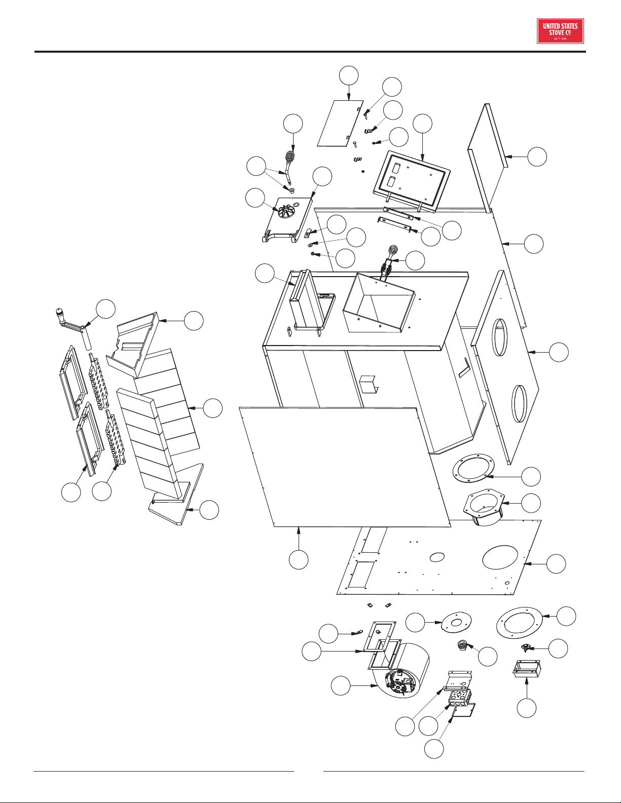
REPAIR PARTS
22
6
8
7
9
20
18
19
17
16
14
10
15
11
12
13
21
1
5
2 3
4
1
28
27
26
29
30
31
24
25
32
33
23
41
39
37
38
40
34
22
© 2021 United States Stove Company
REPAIR PARTS
Key Part # Description Qty
1 25467B Cabinet Side (L & R) 2
2 88032 Flue Collar Gasket 2
3 40246 Flue Collar 1
4 23459B Cabinet Back 1
5 25466B Cabinet Top 1
N/S 891214 8" Collar 2
6 68217 Feed Door Assy. 1
7 22662 Feed Door Bracket 1
8 24232 Hinge Spacer 1
9 891097 Feed Door Locking Mechanism 1
10 68218 Ash Door Assy. 1
11 86626 Door Latch 1
12 83461 Washer (1" OD, 7/16" ID) 1
13 83274 Lock Nut, 3/8-16 1
14 891098 Handle Assy. w/Handle Bushing 1
15 23859B Painted Draft Cap 1
16 891135 Handle, Spring 2
17 23800 Smoke Curtain 1
18 23787 Smoke Curtain Clip 2
19 83445 1/4-20 x 1-1/4 Carriage Bolt 2
20 83250 1/4-20 Kep Nut 2
21 68228 Ash Pan 1
22 23398 Flue Bae 2
23 22761B Flue Collar Ring 1
24 22762B Forced Draft Ring 1
25 86402 1-1/2" Pipe Plug 1
26 80230 Blower 2
27 89319 Gasket, Blower 2
28 83340 1/4-20 Clipnut 8
29 22140 Relay Box Bracket 1
30 80131 Junction Box (4 x 4) 1
31 80231 Junction Box Cover 1
32 80314 Thermodisc (60T12) 1
33 68234 Blower Thermostat Bracket 1
34 89066 Firebrick (4.5 x 9 x 1.25) 12
36 40264 Front/Rear Liner
37 40256 Shaker Grate Frame 2
38 40257 Shaker Grate 2
39 40260 Shaker Handle 1
40 40258 Liner - Front/Rear 1
41 40269 Liner - Front 1
IN ORDER TO MAINTAIN WARRANTY, COMPONENTS MUST BE REPLACED USING ORIGINAL
MANUFACTURERS PARTS PURCHASED THROUGH YOUR DEALER OR DIRECTLY FROM THE APPLIANCE
MANUFACTURER. USE OF THIRD PARTY COMPONENTS WILL VOID THE WARRANTY.
To order parts:
Call 1-800-750-2723 Ext 5051 or
Email to: parts@usstove.com
© 2021 United States Stove Company
23
1
1
2
2
3
3
4
4
A A
B B
1
2
10
11
9
7
12
5
4
6
8
3
7
13
- 69921B Thermostat Box Assembly -
1 68722 Thermostat Panel Weldment 1
2 68732
Thermostat Cover
Weldment (Color - Red)
1
** 68732B
Thermostat Cover
Weldment
1
3 23429 Thermostat Step Plate 1
4 23431 Friction Plate 1
5 81903 Thermostat 1
6 23427
Thermostat Mounting
Bracket
1
7 83172 #10 Sheet Metal Screw 6
8 89041 Spring 1
9 89175 Thermostat Knob 1
10 23425 Handle Bracket 2
11 89520 Wooden Handle 1
12 86318 Thermostat Chain 1/2 ft
13 68217
Feed Door Assembly
(Includes Door and Gasket)
1
N/S 83106S
Machine Screw, 10-24 x 1/2"
SL HD Z
2
N/S 83136
Washer, 9/32" I.D. - 5/8"
O.D. - 1/16" THK.
1
N/S 83816 1/16" x 3/4" Cotter Pin 1
REPAIR PARTS
IN ORDER TO MAINTAIN WARRANTY, COMPONENTS MUST BE REPLACED USING ORIGINAL
MANUFACTURERS PARTS PURCHASED THROUGH YOUR DEALER OR DIRECTLY FROM THE APPLIANCE
MANUFACTURER. USE OF THIRD PARTY COMPONENTS WILL VOID THE WARRANTY.
To order parts:
Call 1-800-750-2723 Ext 5051 or
Email to: parts@usstove.com
24
© 2021 United States Stove Company
It is recommended that your heating system is serviced regularly and that the appropriate Service Interval Record is
completed.
SERVICE PROVIDER
Before completing the appropriate Service Record below, please ensure you have carried out the service as described in
the manufacturer’s instructions. Always use the manufacturer's specified spare part when replacement is necessary.
Service 01 Date: ______________________
Engineer Name: ____________________________________
License No.: ________________________________________
Company: __________________________________________
Telephone No.: _____________________________________
Stove Inspected: Chimney Swept:
Items Replaced: ____________________________________
Service 03 Date: ______________________
Engineer Name: ____________________________________
License No.: ________________________________________
Company: __________________________________________
Telephone No.: _____________________________________
Stove Inspected: Chimney Swept:
Items Replaced: ____________________________________
Service 05 Date: ______________________
Engineer Name: ____________________________________
License No.: ________________________________________
Company: __________________________________________
Telephone No.: _____________________________________
Stove Inspected: Chimney Swept:
Items Replaced: ____________________________________
Service 07 Date: ______________________
Engineer Name: ____________________________________
License No.: ________________________________________
Company: __________________________________________
Telephone No.: _____________________________________
Stove Inspected: Chimney Swept:
Items Replaced: ____________________________________
Service 02 Date: ______________________
Engineer Name: ____________________________________
License No.: ________________________________________
Company: __________________________________________
Telephone No.: _____________________________________
Stove Inspected: Chimney Swept:
Items Replaced: ____________________________________
Service 04 Date: ______________________
Engineer Name: ____________________________________
License No.: ________________________________________
Company: __________________________________________
Telephone No.: _____________________________________
Stove Inspected: Chimney Swept:
Items Replaced: ____________________________________
Service 06 Date: ______________________
Engineer Name: ____________________________________
License No.: ________________________________________
Company: __________________________________________
Telephone No.: _____________________________________
Stove Inspected: Chimney Swept:
Items Replaced: ____________________________________
Service 08 Date: ______________________
Engineer Name: ____________________________________
License No.: ________________________________________
Company: __________________________________________
Telephone No.: _____________________________________
Stove Inspected: Chimney Swept:
Items Replaced: ____________________________________
SERVICE RECORD