Specifications subject to change without notice.
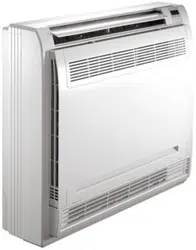
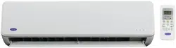
Fig. 1 — Sizes 09K - 24K
NOTES: Read the entire instruction manual before starting the
installation.
Images are for illustration purposes only. Actual models
may differ slightly.
TABLE OF CONTENTS
SAFETY CONSIDERATIONS .....................................................................2
PARTS LIST................................................................................................3
SYSTEM REQUIREMENTS........................................................................4
WIRING .......................................................................................................4
DIMENSIONS - INDOOR ............................................................................5
CLEARANCES - INDOOR ..........................................................................8
INSTALLATION TIPS..................................................................................9
ELECTRICAL DATA....................................................................................12
CONNECTION DIAGRAMS ........................................................................12
FINAL TUBING CHECK ..............................................................................14
WIRELESS REMOTE CONTROL INSTALLATION ....................................14
START-UP ..................................................................................................15
SYSTEM CHECKS.....................................................................................16
TROUBLESHOOTING ................................................................................16
Installation Instructions
40MHH
High Wall Ductless System
Sizes 09 to 24
2 Specifications subject to change without notice. IM-40MHH-02
SAFETY CONSIDERATIONS
Installing, starting up, and servicing air-conditioning equipment can
be hazardous due to system pressures, electrical components, and
equipment location (roofs, elevated structures, etc.).
Only trained, qualified installers and service mechanics should install,
start-up, and service this equipment.
Untrained personnel can perform basic maintenance functions such as
cleaning coils. All other operations should be performed by trained
service personnel.
When working on the equipment, observe precautions in the literature
and on tags, stickers, and labels attached to the equipment.
Follow all safety codes. Wear safety glasses and work gloves. Keep
quenching cloth and fire extinguisher nearby when brazing. Use care
in handling, rigging, and setting bulky equipment.
Read these instructions thoroughly and follow all warnings or
cautions included in literature and attached to the unit. Consult local
building codes and National Electrical Code (NEC) for special
requirements. Recognize safety information.
This is a safety symbol
When you see this symbol on the unit and in instructions or manuals,
be alert to the potential for personal injury. Understand these signal
words: DANGER, WARNING, and CAUTION. These words are
used with the safety-alert symbol. DANGER identifies the most
serious hazards which will result in severe personal injury or death.
WARNING signifies hazards which could result in personal injury or
death. CAUTION is used to identify unsafe practices which may
result in minor personal injury or product and property damage.
NOTE is used to highlight suggestions which will result in enhanced
installation, reliability, or operation.
ELECTRICAL OPERATION HAZARD
Failure to follow this warning could result in personal injury or
death.
Before installing, modifying, or servicing system, main electrical
disconnect switch must be in the OFF position. There may be
more than 1 disconnect switch. Lock out and tag switch with a
WA RNING
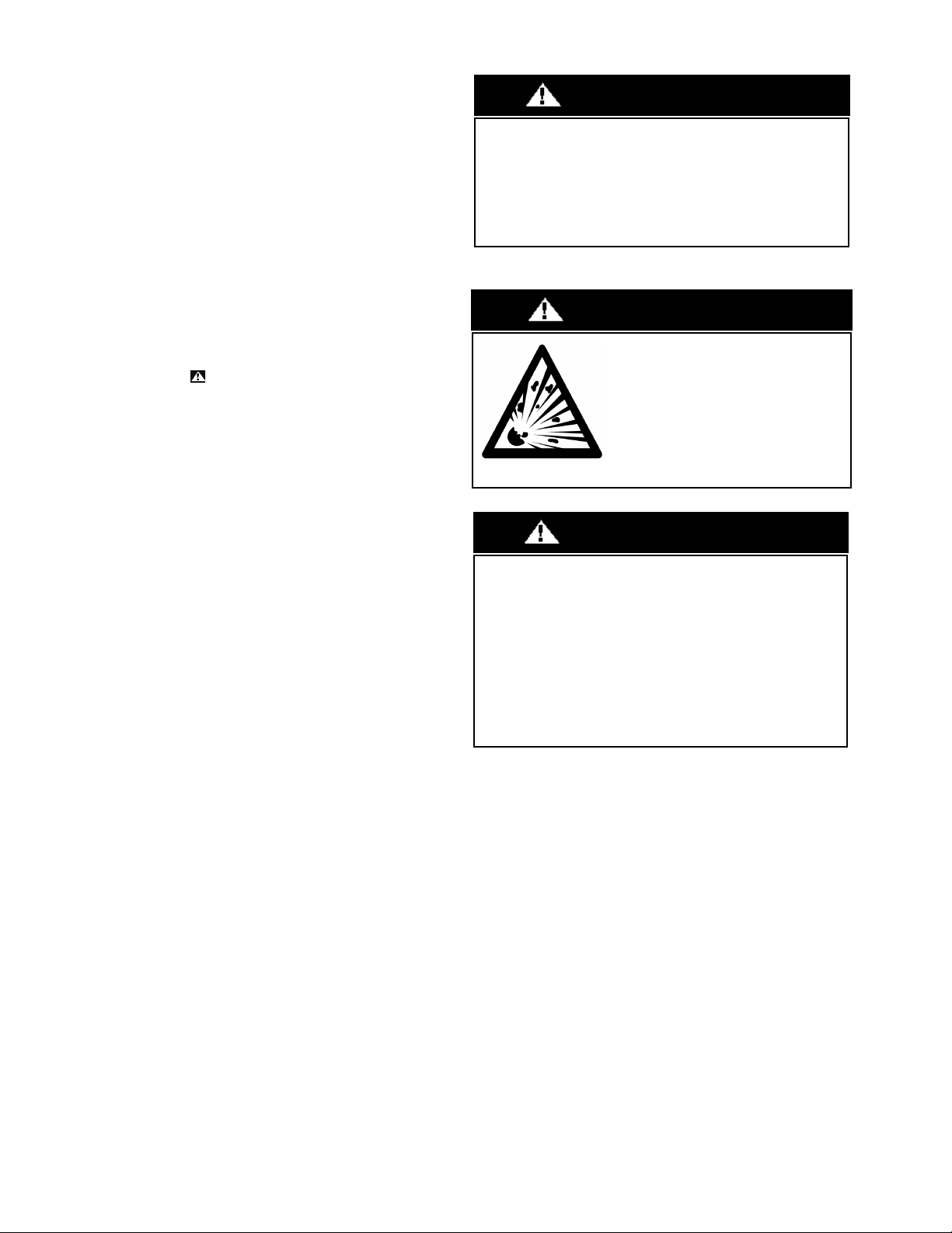
EXPLOSION HAZARD
Failure to follow this warning could
result in death, serious personal injury,
and/or property damage.
Never use air or gases containing oxygen
for leak testing or operating refrigerant
compressors. Pressurized mixtures of air
or gases containing oxygen can lead to
an explosion.
WA RNING
EQUIPMENT DAMAGE HAZARD
Failure to follow this caution may result in equipment damage or
improper operation.
Do not bury more than 36 in. (914 mm) of refrigerant pipe in the
ground. If any section of pipe is buried, there must be a 6 in. (152
mm) vertical rise to the valve connections on the outdoor units. If
more than the recommended length is buried, refrigerant may
migrate to the cooler buried section during extended periods of a
system shutdown. This causes refrigerant slugging and could
possibly damage the compressor during the start-up process.
CAUTION
IM-40MHH-02 Specifications subject to change without notice. 3
PARTS LIST
Table 1 — Parts List
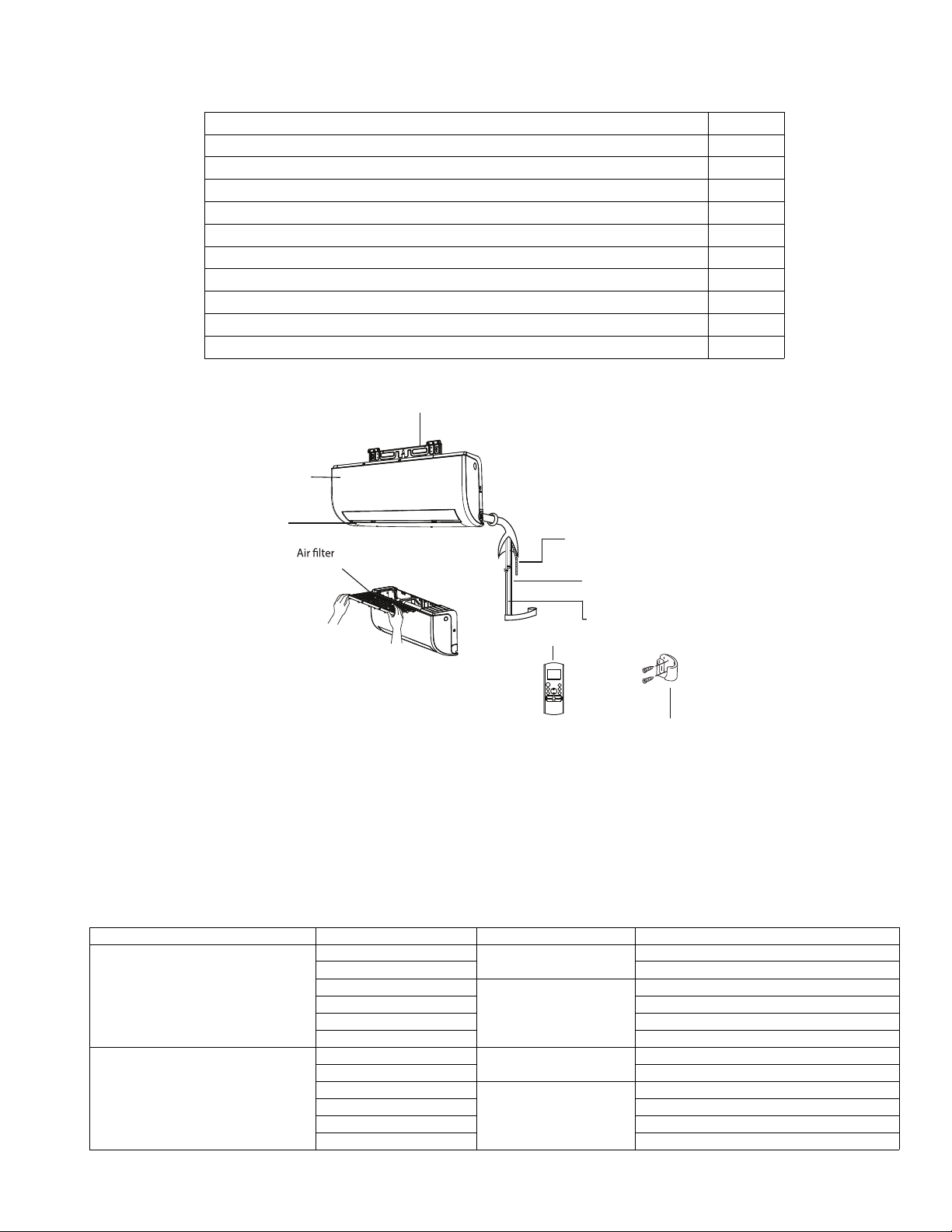
Fig. 2 — Parts List
Note:
- If the outdoor unit is higher than the indoor unit, prevent rain from flowing into the indoor unit along the connection pipe by making a
downward arc in the connection pipe before it enters the wall to the indoor unit. This ensures that rain drips from the connection pipe before it
enters the wall.
- Piping and the interconnecting wiring are field supplied.
- The illustration above is only a sketch. Different models may be slightly different.
The following units are covered in these installation instructions.
Table 2 — Indoor Units
ACCESSORY Quantity
Indoor Unit 1
Wall mounting plate 1
Wall Mounting Screw A ST3.9x25 5
Anchor 5
Air filter 1
Wireless Remote Controller 1
Wireless Remote Controller Holder 1
Remote Control Mounting Screw B ST2.9x10 2
Battery AAA.LR03 2
Multi function board 2
DESCRIPTION KBTUH V-PH-HZ ID MODEL NO.
High Wall Cooling Only
9
15-1-60
40MHHC09---1
12 40MHHC12---1
9
208/230-1-60
40MHHC09---1
12 40MHHC12---3
18 40MHHC18---3
24 40MHHC24---3
High Wall Heat Pump
9
15-1-60
40MHHQ09---1
12 40MHHQ12---1
9
208/230-1-60
40MHHQ09---1
12 40MHHQ12---3
18 40MHHQ18---3
24 40MHHQ24---3
Wall Mounting Plate
Refrigerant Piping (Field Supplied)
Power and Communication Wiring
(Field Supplied)
Wireless Remote Control
Condensate Drain Pipe
(Field Supplied)
Louver
Wireless Remote Holder
Front Panel
(pull it out)
4 Specifications subject to change without notice. IM-40MHH-02
SYSTEM REQUIREMENTS
Allow sufficient space for airflow and servicing unit. See Fig. 7 — on page 8 for minimum required distances between unit and walls or
ceilings.
Piping
IMPORTANT: Both refrigerant lines must be insulated separately.
Table 3 lists the pipe sizes for the indoor unit. Refer to the outdoor unit installation instructions for other allowed piping lengths and
refrigerant information.
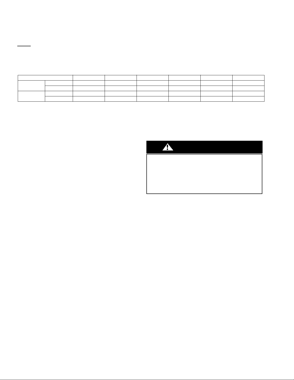
Table 3 — Indoor Unit Pipe Sizes
WIRING
All wires must be sized per NEC (National Electrical Code) or
CEC (Canadian Electrical Code) and local codes. Use the Electrical
Data table MCA (minimum circuit amps) and MOCP (maximum
over current protection) to correctly size the wires and the
disconnect fuse or breakers respectively.
Per caution note, only stranded copper conductors with a 600 volt
rating and double insulated copper wire must be used. The use of
BX cable is not recommended.
Recommended Connection Method for Power and
Communication Wiring − Power and Communication Wiring:
The main power is supplied to the outdoor unit. The field supplied
14/3 power/communication wiring from the outdoor unit to the
indoor unit consists of four (4) wires and provides the power for
the indoor unit. Two wires are high voltage AC power, one is
communication wiring and the other is a ground wire.
Recommended Connection Method for Power and
Communication Wiring (To minimize communication wiring
interference) Power Wiring:
The main power is supplied to the outdoor unit. The field supplied
power wiring from the outdoor unit to the indoor unit consists of
three (3) wires and provides the power for the indoor unit. Two
wires are high voltage AC power and one is a ground wire.
To minimize voltage drop, the factory recommended wire size is
14/2 stranded with a ground.
Communication Wiring:
A separate shielded stranded copper conductor only, with a 600
volt rating and double insulated copper wire, must be used as the
communication wire from the outdoor unit to the indoor unit.
Please use a separate shielded 16GA stranded control wire.
UNIT SIZE 9K (115) 12K (115V) 9K (208/230V) 12K (208/230V) 18K (208/230V) 24K (208/230V)
Gas Pipe
in 3/8 1/2 3/8 1/2 1/2 5/8
(mm) 9.52 12.7 9.52 12.7 12.7 16
Liquid Pipe
in 1/4 1/4 1/4 1/4 1/4 3/8
(mm) 6.35 6.35 6.35 6.35 6.35 9.52
EQUIPMENT DAMAGE HAZARD
Failure to follow this caution may result in equipment damage or
improper operation.
Wires should be sized based on NEC and local codes.
Use copper conductors only with a 600 volt rating and double
insulated copper wire.
CAUTION
IM-40MHH-02 Specifications subject to change without notice. 5
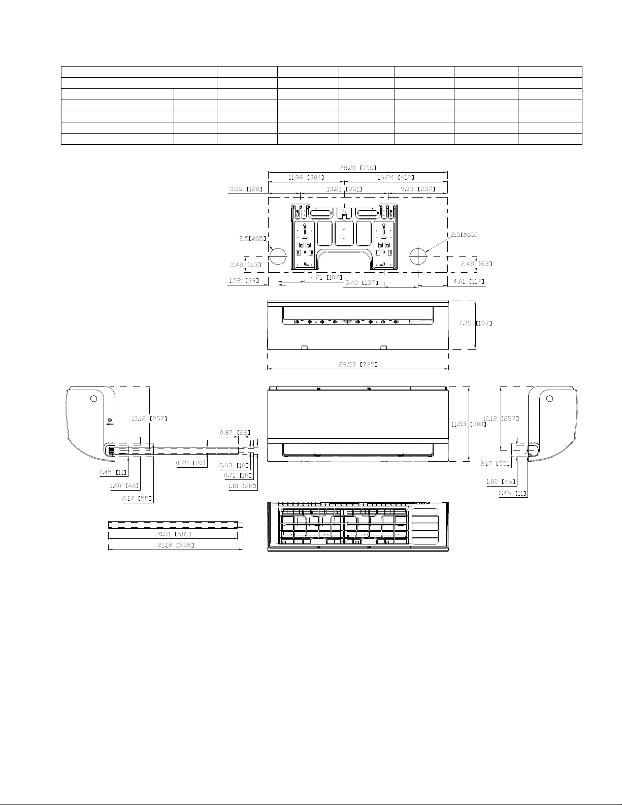
DIMENSIONS - INDOOR
Table 4 — Indoor Unit Dimensions
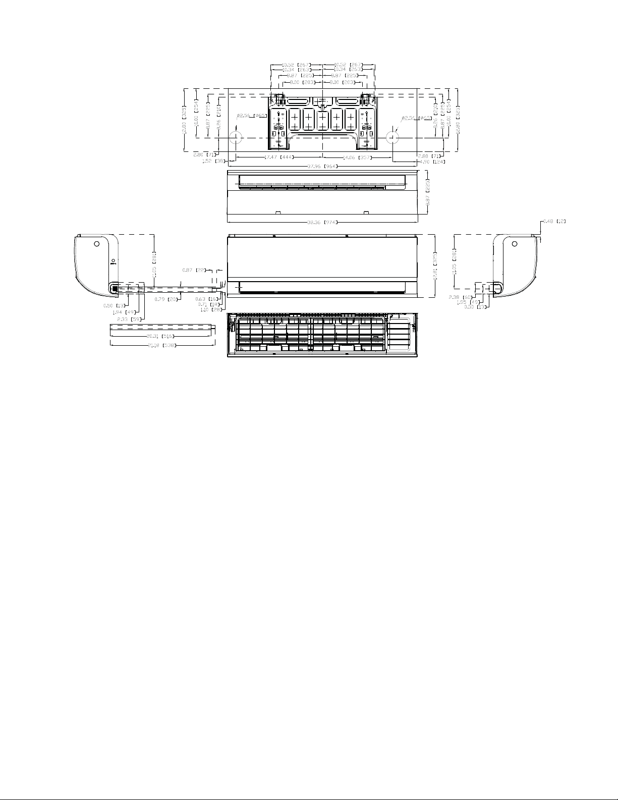
Fig. 3 — Size 9K
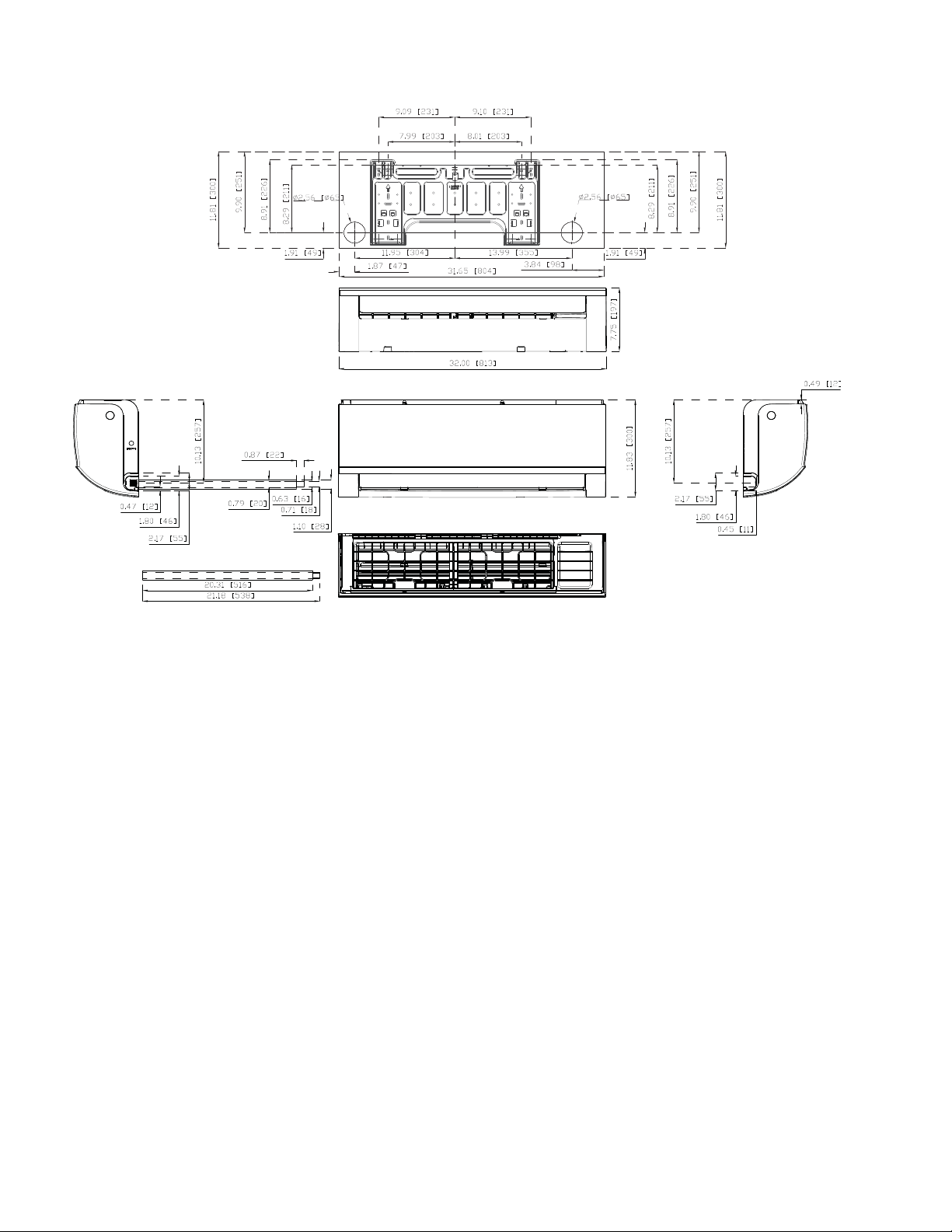
HIGH WALL UNIT SIZE 9K 12K 9K 12K 18K 24K
VOLTAGE (115V) (115V) (208/230V) (208/230V) (208/230V) (208/230V)
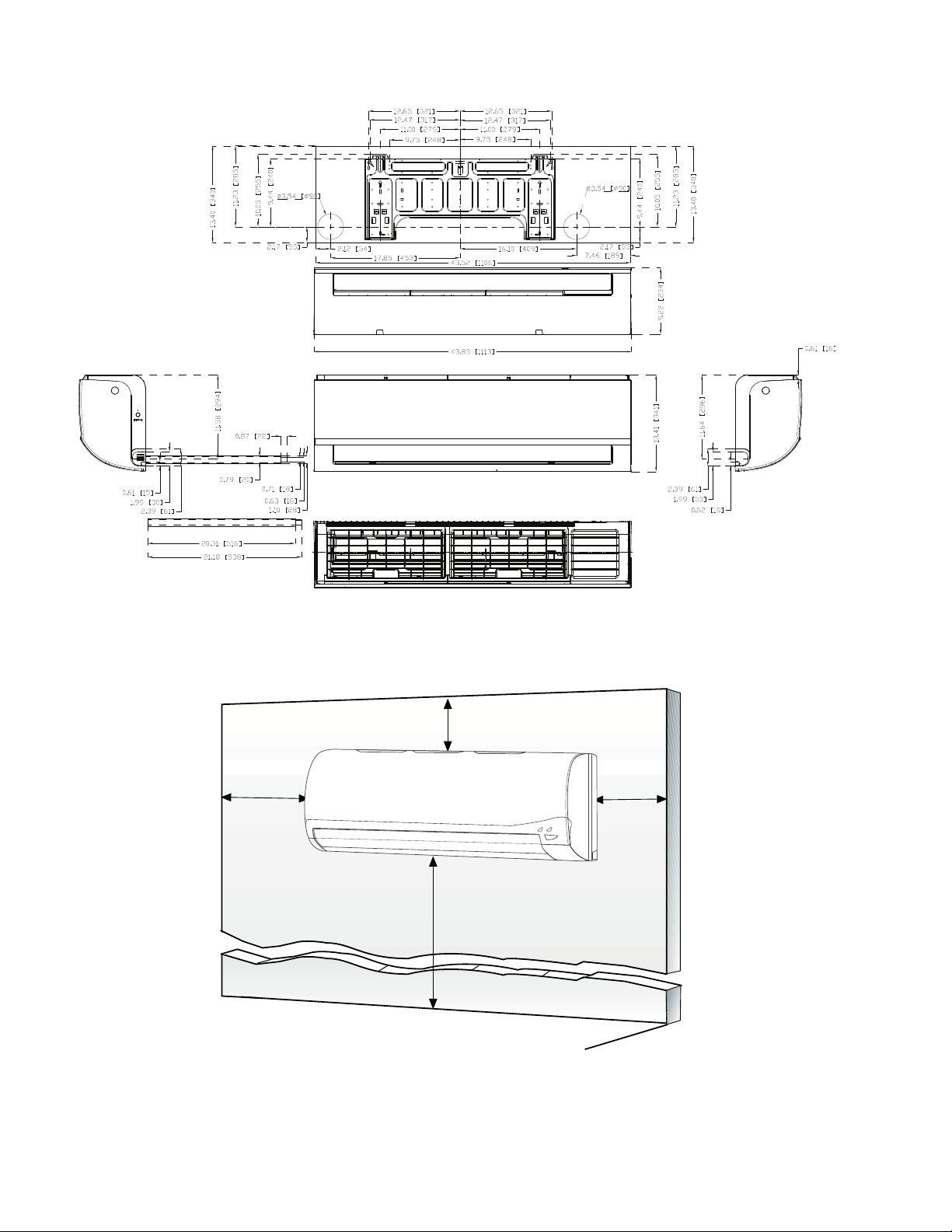
Height In (mm) 11.81 (300) 11.81 (300) 11.81 (300) 11.81 (300) 12.8 (325) 13.41 (341)
Width In (mm) 28.53 (725) 32.00 (813) 28.53 (725) 32.00 (813) 38.36 (974) 43.83 (1113)
Depth In (mm) 7.75 (197) 7.75 (197) 7.75 (197) 7.75 (197) 8.87 (225) 9.22 (234)
Weight - Net (Cooling Only) Lbs. (kg) 16.53 (7.5) 17.64 (8) 16.53 (7.5) 17.64 (8) 23.15 (10.5) 30.86 (14)
Weight - Net (Heat Pump) Lbs. (kg) 21.83 (9.9) 22.49 (10.2) 21.16 (9.6) 22.49 (10.2) 31.97 (14.5) 40.12 (18.2)
Units: Inches [mm]
6 Specifications subject to change without notice. IM-40MHH-02
DIMENSIONS (CONT)
Fig. 4 — Size 12K
Units: Inches [mm]
IM-40MHH-02 Specifications subject to change without notice. 7
DIMENSIONS (CONT)
Fig. 5 — Size 18
Units: Inches [mm]
8 Specifications subject to change without notice. IM-40MHH-02
DIMENSIONS (CONT)
Fig. 6 — Size 24
CLEARANCES - INDOOR
Fig. 7 — Indoor Unit Clearances
Units: Inches [mm]
6
in )
min.
5
in
(127mm)
min.
6 ft
5
in
(127mm)
min.
(1.8m)
FLOOR
(152mm
IM-40MHH-02 Specifications subject to change without notice. 9
INSTALLATION TIPS
Ideal installation locations include:
Indoor Unit
• A location where there are no obstacles near inlet and outlet area.
• A location which can bear the weight of indoor unit.
• Do not install indoor units near a direct source of heat such as
direct sunlight or a heating appliance.
• A location which provides appropriate clearances (see Fig. 7.)
Indoor Unit Installation
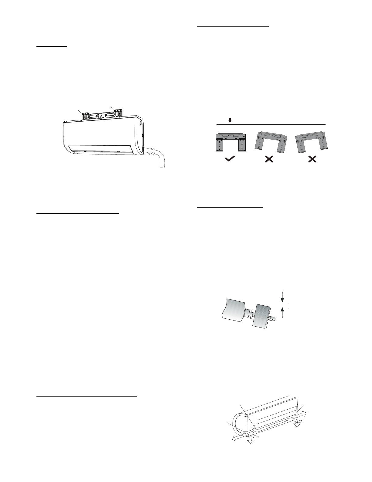
Fig. 8 — High Wall Unit
Prior to Installation
Before installing the indoor unit, ensure the compatibility with the
outdoor unit using the product data as a reference.
Select the Installation Location:
Before installing the indoor unit, choose an appropriate location.
The following are standards that should help you choose an
appropriate location for the unit. Proper installation locations must
meet the following standards:
1. Good air circulation
2. Convenient drainage
3. Noise from the unit will not disturb others
4. Firm and solid—the location will not vibrate
5. A site strong enough to support the weight of the unit
6. A location at least 3.28 ft. (1m) from all other electrical devices
(e.g., TV, radio, computer)
7. DO NOT install the unit in the following locations:
a. Near any source of heat, steam, or combustible gas
b. Near flammable items such as curtains or clothing
c. Near any obstacle that might block air circulation
d. Near the doorway
e. In a location subject to direct sunlight
NOTE: Wall Holes: If there is no fixed refrigerant piping. While
choosing a location, you should leave ample room for a wall hole
(refer to the Drill wall hole for connective piping step) for the
signal cable and refrigerant piping that connect the indoor and
outdoor units. The default position for all piping is the right side
of the indoor unit (while facing the unit). However, the unit can
accommodate piping to both the left and right.
Attach the Mounting Plate to the Wall:
1. Carefully remove the mounting plate, which is attached to the back
of the indoor unit.
2. The mounting plate should be located horizontally and level on the
wall. All minimum spacings (see Fig. 7) should be maintained.
3. If the wall is block, brick, concrete or similar material, drill 0.2” (5
mm) diameter holes and insert anchors for the appropriate
mounting screws.
4. Attach the mounting plate to the wall.
Mounting Plate Dimensions
Different model sizes have different mounting plates. Ensure there’s
enough room to mount the indoor unit (refer to Fig. 3−6).
The following measurements can be located on these figures:
• Width of mounting plate
• Height of mounting plate
• Width of indoor unit relative to plate
• Height of indoor unit relative to plate
• Recommended position of wall hole (both to the left and right of
mounting plate)
• Relative distances between screw holes.
Fig. 9 — Mounting Plate Orientation
DRILL HOLE IN WALL FOR THE
INTERCONNECTING PIPING, DRAIN AND WIRING
Refrigerant Line Routing
The refrigerant lines may be routed in any of the four directions
(see Fig. 11).
For maximum serviceability, it is recommended to have refrigerant
line flare connections and the drain connections on the outside of
the wall that the fan coil can be mounted on.
If piping is going through the back:
1. Determine the pipe hole position using the mounting plate as a
template. Drill pipe hole diameter per values given in Figures 3−6.
The outside pipe hole is 1/2−in. (13 mm) min. lower than inside
pipe hole, so it slants slightly downward (see Fig. 11).
Fig. 10 — Drill Holes
If piping is going through the right or left side:
1. Use a small saw blade to carefully remove the corresponding plastic
covering on side panel and drill the appropriate size hole where the
pipe is going through the wall.
Fig. 11 — Piping Locations
Correct orientation of Mounting Plate
1/2 in. (13 mm
)
Min.
I
NDOOR
OUTDOOR
Pipe holder
Pip
e cover
Right piping
Left piping
Pipe cover
Right back piping
Left back
piping
1
2
3
4
10 Specifications subject to change without notice. IM-40MHH-02
Prepare the Refrigerant Piping
The refrigerant piping is inside an insulating sleeve attached to the
back of the unit. You must prepare the piping before passing it
through the hole in the wall.
NOTE: (Piping Angle) Refrigerant piping can exit the indoor unit
from four different angles (see Fig. 12):
1. Left−hand side
2. Left rear
3. Right−hand side
4. Right rear
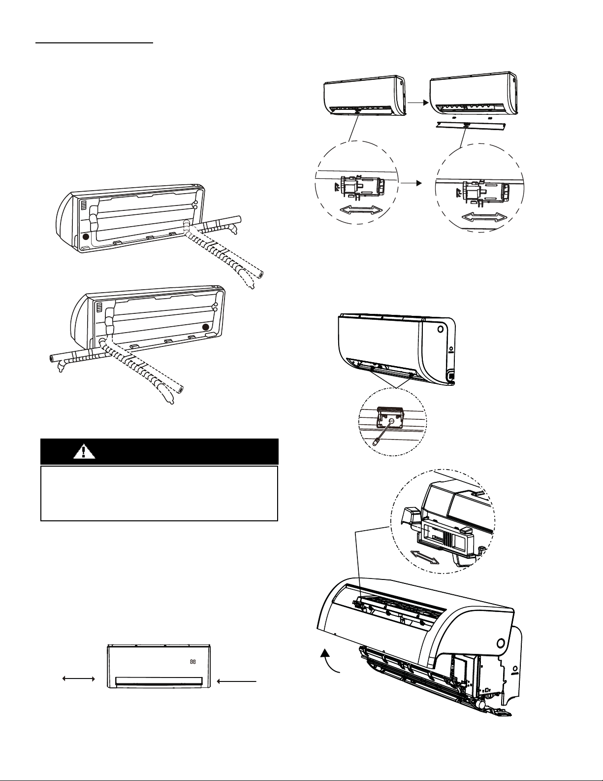
Fig. 12 — Piping Angles
If the refrigerant piping is already embedded in the wall, perform the
following steps:
1. Hook the indoor unit on the mounting plate. Keep in mind that
the hooks on the mounting plate are smaller than the holes on the
back of the unit. If you find that you do not have ample room to
connect the embedded pipes to the indoor unit, the unit can be
adjusted left or right by about 1.25−1.95in. (30−50mm), depending
on the model (see Fig. 13).
Fig. 13 — Hook Indoor Unit to Mounting Plate
2. Prepare the Refrigerant Piping
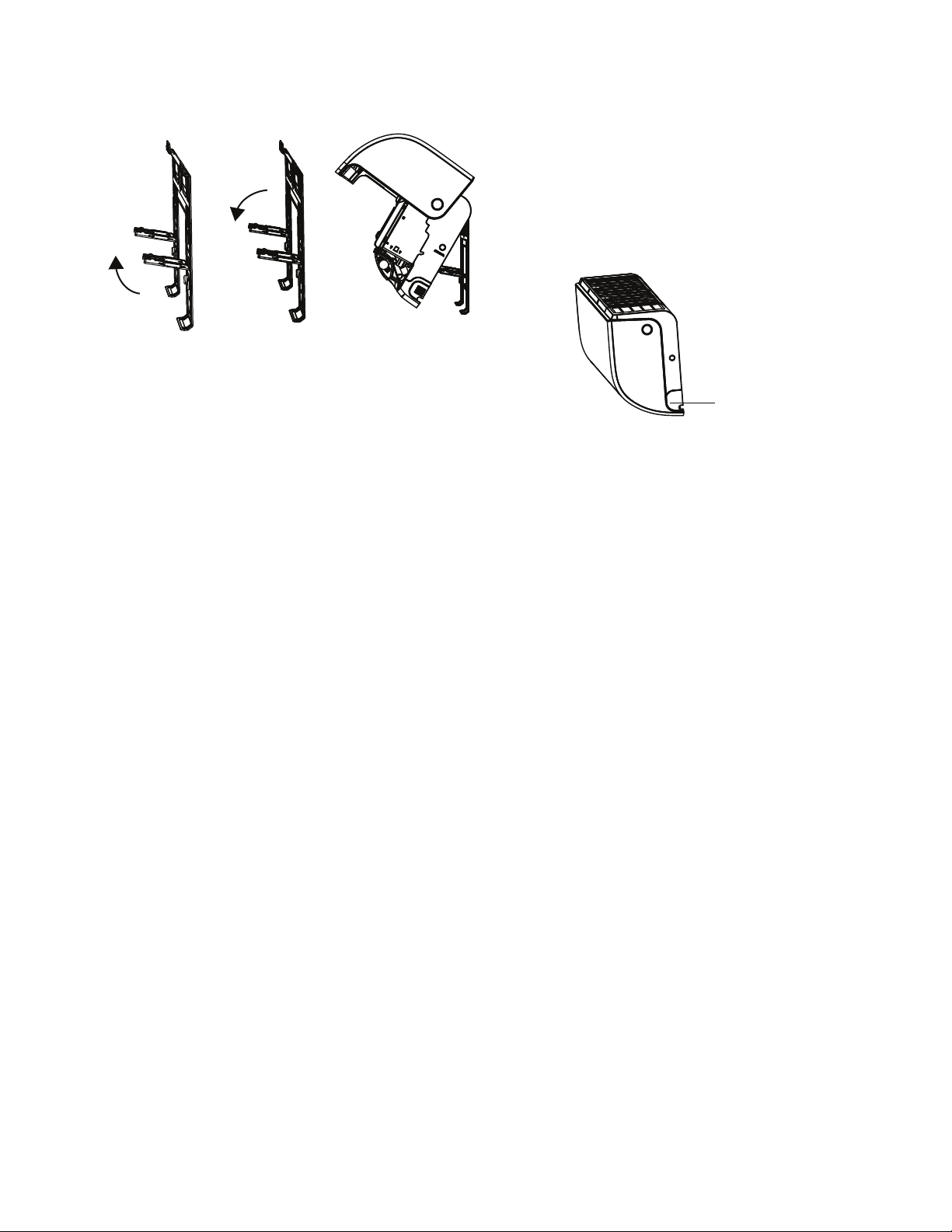
1. Dissemble the louver.
Fig. 14 — Dissemble the Louver
2. Open and fix the position of the panel. First, unscrew the
two screws (see Fig. 15), then open the panel, and fix the
position of the panel by the latch.
Fig. 15 — Panel Position
ELECTRICAL OPERATION HAZARD
Be extremely careful not to dent or damage the piping while
bending them away from the unit. Any dents in the piping will
affect the unit’s performance.
CAUTION
Move to left or right
1.25−1.95in
(30−50mm)
1.25−1.95in
(30−50mm)
IM-40MHH-02 Specifications subject to change without notice. 11
3.
Use the holder in the mounting plate to prop up the unit,
allowing you enough space to connect the refrigerant
piping, signal cable, and the drain hose
.
Fig. 16 — Use Holder to Prop up the unit
3. Connect the drain hose and refrigerant piping.
4. Keep the pipe connection point exposed to perform the leak test.
5. After the leak test, wrap the connection point with insulation tape.
6. Remove the bracket or wedge that is propping with insulation tape.
7. Using even pressure, push down on the bottom half of the unit.
Keep pushing down until the unit snaps onto the hooks along the
bottom of the mounting plate.
If there is no refrigerant piping embedded in the wall, perform the
following steps:
1. Based on the position of the wall hole relative to the mounting
plate, choose the side from which the piping will exit the unit.
2. If the wall hole is behind the unit, keep the knock−out panel in
place. If the wall hole is to the side of the indoor unit, remove the
plastic knock−out panel from that side of the unit (see Fig. 17). This
creates a slot through which your piping can exit the unit. Use
needle nose pliers if the plastic panel is too difficult to remove by
hand.
Fig. 17 — Knock Out Panel
3. Use scissors to cut down the length of the insulating sleeve to reveal
about 1.57in. (40mm) of the refrigerant piping.
This serves two purposes:
(1.) To facilitate the refrigerant piping connection process
(2.) To facilitate Gas Leak Checks and enable you to check for
dents.
4. Connect the indoor unit’s refrigerant piping to the connective
piping that joins the indoor and outdoor units.
5. Based on the position of the wall hole relative to the mounting
plate, determine the necessary angle of your piping.
6. Grip the refrigerant piping at the base of the bend.
7. Slowly, with even pressure, bend the piping towards the hole. Do
not dent or damage the piping during the process.
Knock-out Panel
12 Specifications subject to change without notice. IM-40MHH-02
ELECTRICAL DATA
Table 5 — Electrical Data
LEGEND
FLA - Full Load Amps
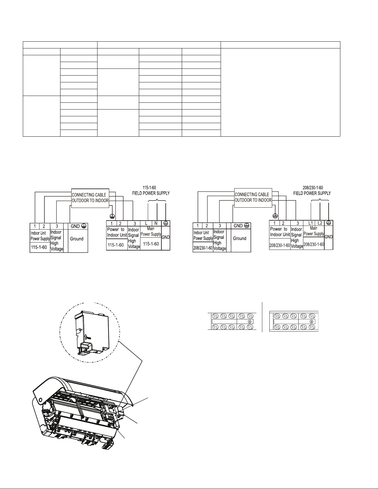
CONNECTION DIAGRAMS
Fig. 18 — Connection Diagram 115V
Fig. 19 — Connection Diagram 230V
NOTES:
1. Do not use thermostat wire for any connection between indoor and outdoor units.
2. All connections between indoor and outdoor units must be as shown. The connections are sensitive to polarity and will result in a fault code.
Fig. 20 — Wiring Diagram Location
Fig. 21 — Control and Power Wiring on the Indoor Unit
HIGH WALL UNIT SIZE INDOOR FAN MAX FUSE CB AMP
V-Ph-Hz FLA HP
Refer to outdoor unit installation instructions –
Indoor unit powered by the outdoor unit
Cooling Only
Models
9K
115-1-60
0.425 0.02
12K 0.425 0.02
9K
208/230-1-60
0.235 0.027
12K 0.235 0.027
18K 0.4 0.037
24K 0.6 0.061
Heat Pump
Models
9K
115-1-60
0.425 0.02
12K 0.47 0.027
9K
208/230-1-60
0.25 0.027
12K 0.34 0.027
18K 0.4 0.037
24K 0.45 0.078
Terminal
block
Wire
cover
Cable
clamp
123 1 2 3
9K and 12K 115V 9K to 24K 208/230V
IM-40MHH-02 Specifications subject to change without notice. 13
Install All Power, Interconnecting Wiring, and
Piping to the Indoor Unit
1. Run the interconnecting piping and wiring from the outdoor unit to
indoor unit.
2. Run the interconnecting cable through hole in wall (outside to
inside).
3. Lift the indoor unit into position and route piping and drain through
the hole in wall (inside to outside). Fit the interconnecting wiring
into back side of indoor unit.
4. Put the upper claw at back of indoor unit on upper hook of
Mounting Plate, move indoor unit from side to side to see that it is
securely hooked.
5. Open the indoor unit’s front panel by loosening the screws, which
provides a large space for wiring connection.
6. Open the wire box cover to connect the cable.
7. Pull the interconnecting wire up from back of indoor unit and
position in close to the terminal block on indoor unit.
8. Push the lower part of indoor unit up on wall, then move indoor unit
from side to side, up and down to check if it is hooked securely (see
Fig. 22).
Fig. 22 — Indoor Unit Installation
9. Connect wiring from outdoor unit per connection diagram (see Fig.
18 and Fig. 19).
10. Replace the wire cover on the front of the unit, and the plastic panel
on the back.
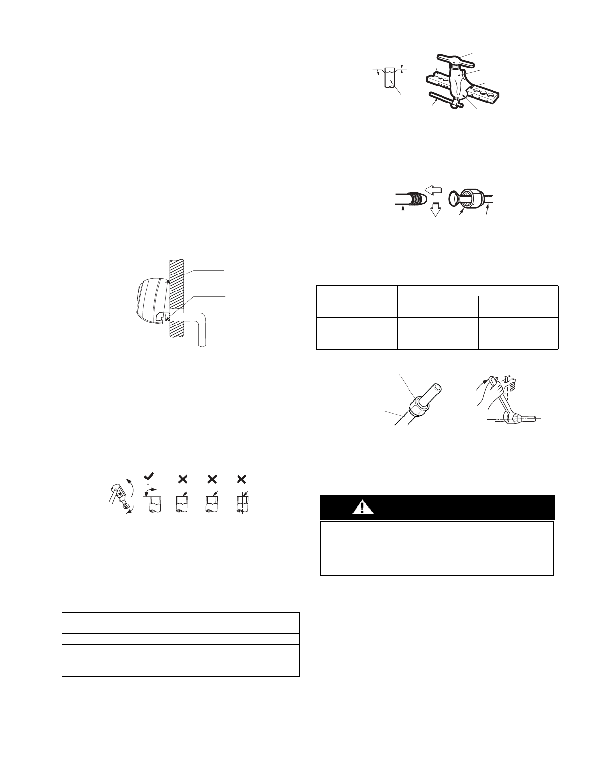
Piping
a. Cut the pipe, with a pipe cutter, at 90 degrees (see Fig. 23).
b. Remove the service connection, if provided with the unit.
Fig. 23 — Pipe Cutting
c. Remove all the burrs from the cut cross section of the pipe
avoiding any burrs inside the tubes.
d. Remove the flare nuts attached to the indoor and outdoor
units.
e. Install the correct size flare nut onto the tubing and make the
flare connection. Refer to Table 6 for the flare nut spaces.
Table 6 — Flare Nut Spacing
Fig. 24 — Flare Nut Spacing
f. Apply a small amount of refrigerant oil to the flare
connection on the tubing.
g. Align center of the pipes and/or service valve.
Fig. 25 — Align Pipe Center
h. Connect both the liquid and gas piping to the indoor unit
i. Tighten the flare nut using a torque wrench as specified in
Table 7.
Table 7 — Tightening Torque
Fig. 26 — Tighten the flare nut
For additional diagnostic information, refer to the Service Manual.
Refrigerant tubes and indoor coil should be evacuated using the
recommended deep vacuum method of 500 microns. The alternate
triple evacuation method may be used if the procedure outlined below
is followed. Always break a vacuum with dry nitrogen.
OUTER DIAM INCH (MM)
A INCH (MM)
MAX. MIN.
Ø 1/4” (6.35) 0.05 (1.3) 0.03 (0.7)
Ø 3/8” (9.52) 0.06 (1.6) 0.04 (1.0)
Ø 1/2” (12.7) 0.07 (1.8) 0.04 (1.0)
Ø 5/8” (15.88) 0.09 (2.2) 0.08 (2.0)
Upper hook
Lower hoo
k
Oblique
90
Roughness
Burr
PIPE DIAMETER
INCH (MM)
TIGHTENING TORQUE
Ft-lb N - m
Ø1/4” (6.35) 10 to 13 13.6 to 17.6
Ø3/8” (9.52) 24 to 31 32.5 to 42.0
Ø1/2” (12.7) 37 to 46 50.1 to 62.3
Ø5/8” (15.88) 50 to 60 67.7 to 81.3
Bar
Copper pipe
Clamp handle
Red arrow mark
Cone
Yoke
Handle
Bar
"A"
Indoor unit tubing Flare nut Piping
Flare nut
Coppe
r tube
UNIT DAMAGE HAZARD
Failure to follow this caution may result in equipment damage or
improper operation.
Never use the system compressor as a vacuum pump.
CAUTION
14 Specifications subject to change without notice. IM-40MHH-02
FINAL TUBING CHECK
IMPORTANT: Ensure certain factory tubing on the indoor unit
has not shifted during shipment. Ensure tubes are not rubbing
against each other or any sheet metal. Pay close attention to feeder
tubes, making sure wire ties on feeder tubes are secure and tight.
Drain Connections
Connect the drain line. The drain line must not have a trap anywhere
in its length, must pitch downwards, and must be insulated up to the
outside wall (see Fig. 27). By default, the drain hose is attached to the
left−hand side of unit (when facing the back of the unit). However, it
can also be attached to the right−hand side.
a. To ensure proper drainage, attach the drain hose on the
same side that your refrigerant piping exits the unit.
b. Attach a drain hose extension (purchased separately) to the
end of drain hose.
c. Wrap the connection point firmly with Teflon tape to
ensure good seal and to prevent leaks.
d. For the portion of the drain hose that will remain indoors,
e. Wrap it with foam pipe insulation to prevent condensation.
f. Remove the air filter and pour a small amount of water into
the drain pan to ensure that water flows from the unit
smoothly.
Plug the Unused Drain Hole
To prevent unwanted leaks you must plug the unused drain hole with
the rubber plug provided.
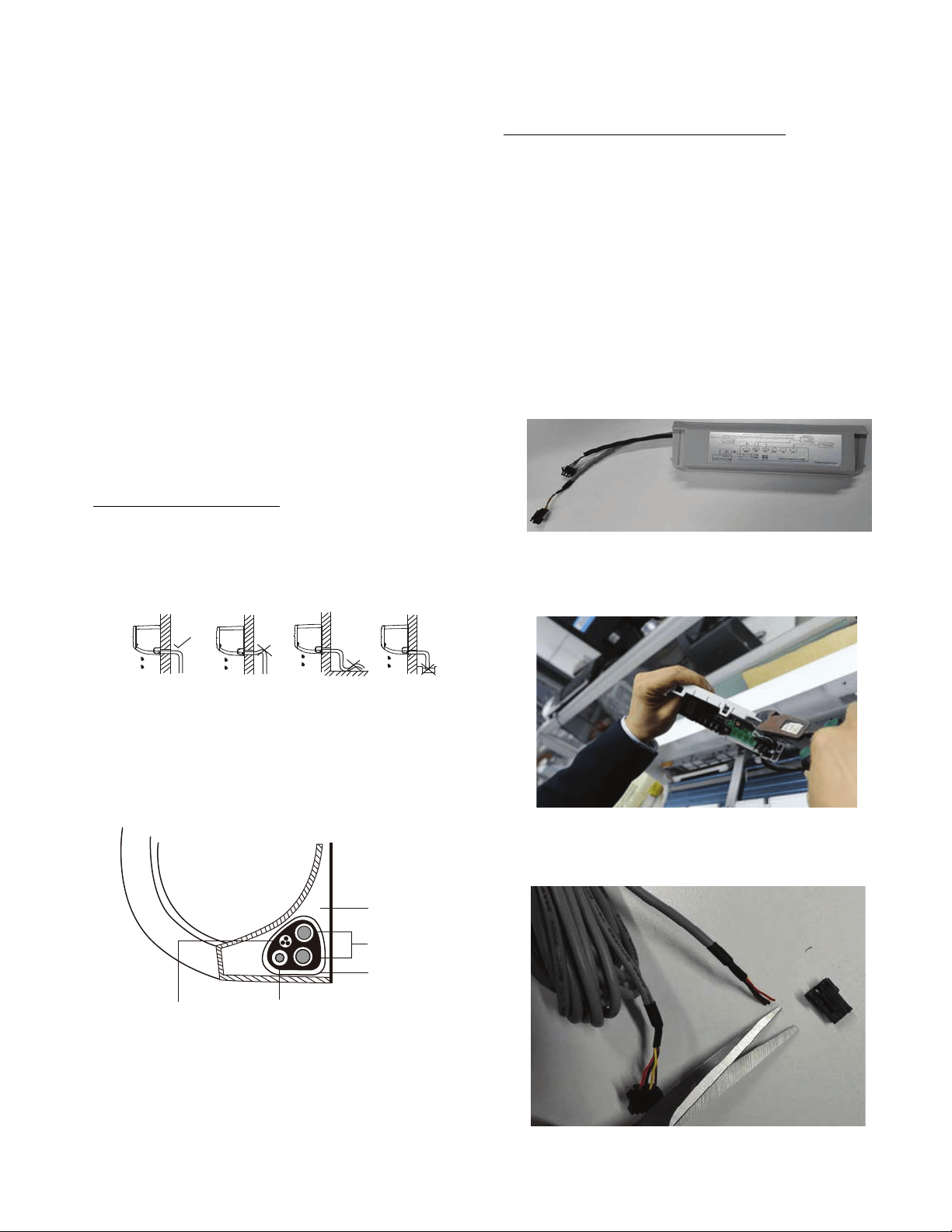
Fig. 27 — Proper Drain Hose Installation
NOTE: For proper orientation of the refrigerant piping, electrical
cable and drain lines, refer to Fig. 28.
Fig. 28 — Bundle drain hose, refrigerant pipes, & signal cable
NOTE: For applications where gravity cannot be used for
drainage, a condensate pump accessory is available. Consult the
condensate pump Installation Instructions for more information.
WIRELESS REMOTE CONTROL
INSTALLATION
Mounting Bracket (if installed on the wall)
1. Use the two screws supplied with control to attach the mounting
bracket to the wall in a location selected by customer and within
operating range.
2. Install batteries in the remote control.
3. Place the remote control into the remote control mounting bracket.
NOTE: For remote control operation, refer to the unit Owner’s
Manual.
WIRED REMOTE CONTROLLER
INSTALLATION
For setup instructions, refer to the wired controller installation
manual.
1. Use the multi−function board supplied.
Fig. 29 — Multi Function Board
2. Use needle nose pliers to cut a hole on the multi-function board for
wiring.
Fig. 30 — Cut a hole on the multi-function board
3. Cut the female plug from the cable supplied with the wired remote
controller and strip the wires to connect to the adaptor board.
Fig. 31 — Cut the female plug and strip the wires
retaw otni dne niard tup ton oDreporP Do not form a rise
Indoor Unit
Space behind unit
Refrigerant piping
Drain hose
Signal wire
Insulation tape
IM-40MHH-02 Specifications subject to change without notice. 15
4. Connect the wired remote controller cable to the multi-function
board using:
a. X—Brown
b. Y—Yellow
c. E—Black (ground)
d. 5V—Red (power)
Fig. 32 — Connect the cable to the board
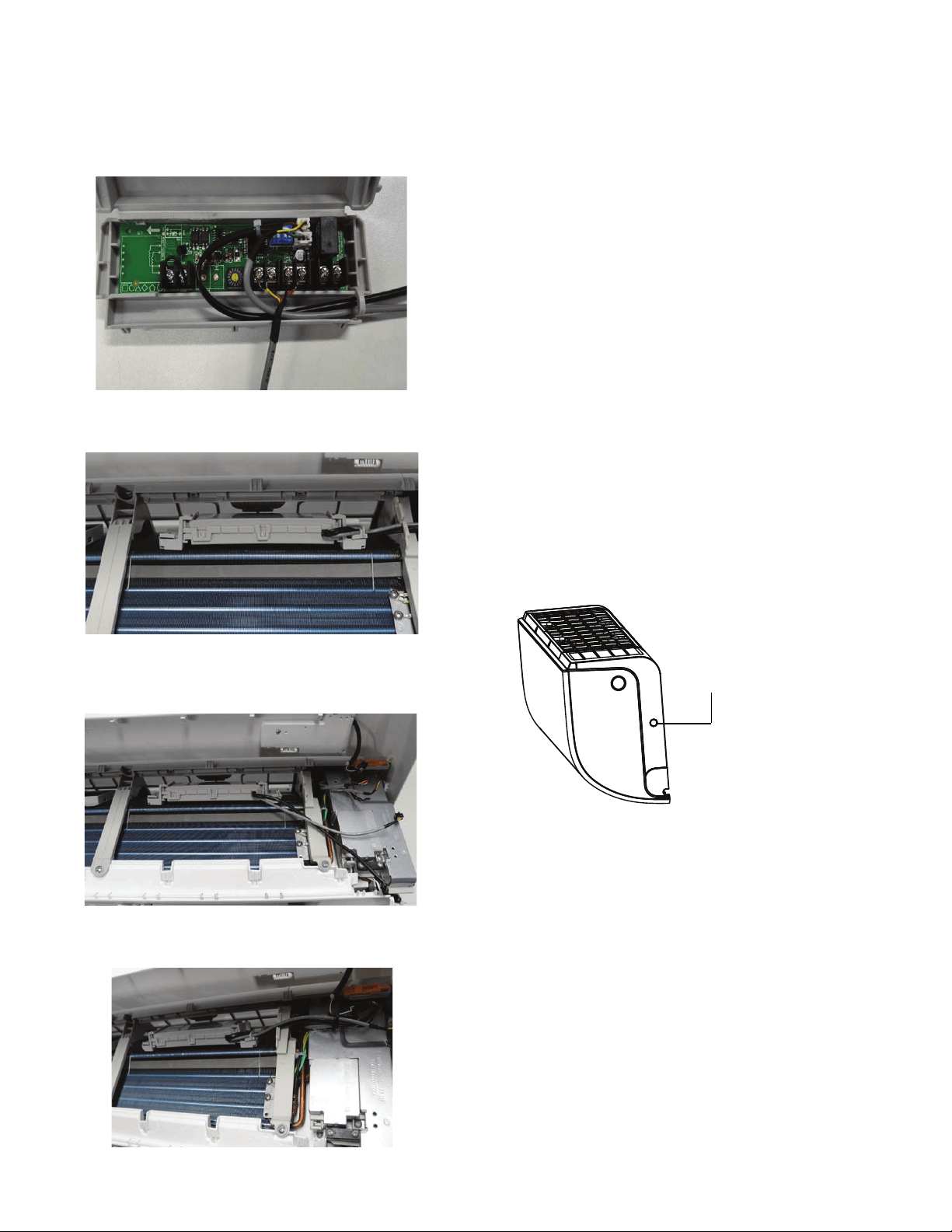
5. Install the multi-function board on the bracket located above the coil.
Fig. 33 — Install the multi-function board
6. Connect the multi-function board to the display board (black cable)
and the main control board (gray cable).
Fig. 34 — Connect the multi-function board
7. Use the ties in the control box to keep the wiring in the right position.
Fig. 35 — Use ties to keep wiring aligned
START-UP
Test Operation
Perform a test operation after completing gas leak and electrical
safety check (see Fig. 36).
1. Push ON/OFF on the remote control to begin testing.
NOTE: A protection feature prevents air conditioner from being
activated for approximately 3 to 4 minutes.
2. Push MODE, select COOLING, HEATING, FAN mode to check
that all functions work correctly.
3. To run the test using MANUAL on the indoor unit:
a. Open front panel of the indoor unit;
b. Push MANUAL once to energize the unit. The set
conditions of manual operation are as follows:
•Preset set point: 76F (24C)
•Fan speed: AUTO
•Discharge air direction: Pre-set position based on operation in
“COOL” or “HEAT” mode.
4. Be sure to set manual switch to the “OFF” position (by pushing it
twice again) after finishing test operation.
NOTE: If the ambient temperature is below 63F (17C). The
remote controller can not be used to turn on the COOL function
when the ambient temperature is below 63F (17C). In this
instance, MANUAL CONTROL can be used to test the
COOL function.
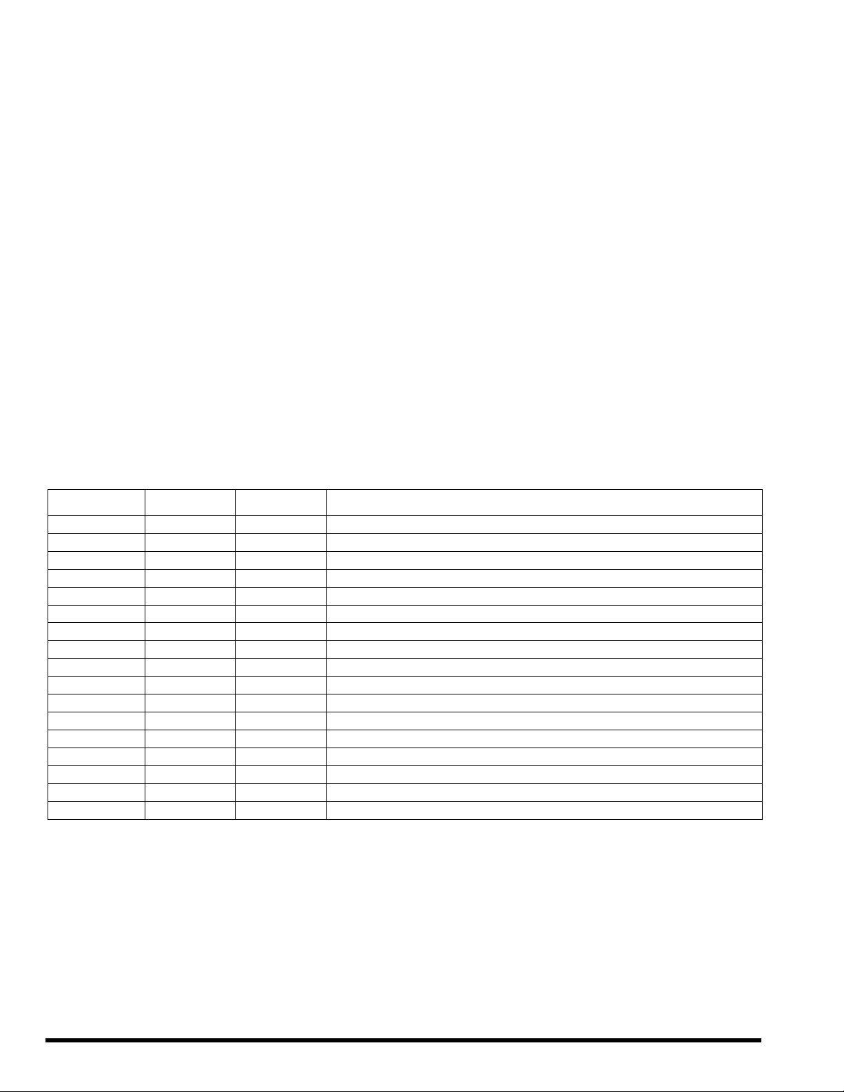
MANUAL CONTROL is located on the right- hand side panel of the
unit (see Fig. 36). Press the button two times to select the COOL
function. Perform a Test Run as normal.
Fig. 36 — Test Operation
Manual control button
Copyright 2021 CAC / BDP D 3300 Riverwood Parkway Atlanta GA, 30339 Edition Date: 01/21 Catalog No. IM-40MHH-02
Manufacturer reserves the right to discontinue, or change at any time, specifications or designs without notice and without incurring obligations. Replaces: IM-40MHH-01
SYSTEM CHECKS
1. Conceal the tubing where possible.
2. Make sure that the drain tube slopes downward along its entire
length.
3. Ensure all tubing and connections are properly insulated.
4. Fasten tubes to the outside wall, when possible.
5. Seal the hole through which the cables and tubing pass.
Indoor Unit
1. Do all remote control buttons function properly?
2. Do the display panel lights work properly?
3. Does the air deflection louver function properly?
4. Does the drain work?
Explain Following Items To Customer (with the aid of the
Owner’s Manual):
1. How to turn air conditioner on and off; selecting COOLING,
HEATING and other operating modes; setting a desired
temperature; setting the timer to automatically start and stop air
conditioner operation; and all other features of the remote control
and display panel.
2. How to remove and clean the air filter.
3. How to set air deflection louver.
4. Explain care and maintenance.
5. Present the Owner’s Manual and installation instructions to
customer.
TROUBLESHOOTING
For ease of service, the systems are equipped with diagnostic code display LEDs on both the indoor and outdoor units. The indoor diagnostic
display is a combination of flashing LEDs on the display panel or the front of the unit.
Some indoor units display error codes specifying failure modes in outdoor units. If possible, always check the diagnostic codes displayed on the
indoor unit first.
The diagnostic codes displayed in the indoor and outdoor units are listed in the Table 8.
INDOOR UNIT DIAGNOSTIC GUIDES
Table 8 — Indoor Unit Diagnostic Guides
O (light) X (off) «(flash)
OPERATION
LAMP
TIMER LAMP DISPLAY LED STATUS
1 time
X
E0 Indoor unit EEPROM parameter error
2 times
X
E1 Indoor / outdoor units communication error
8 times
X
E2 Zero-crossing signal detection error
4 times
X
E3 Indoor fan speed is out of control
5 times
X
E4 Indoor room temperature sensor T1 open circuit or short circuit
6 times
X
E5 Evaporator coil temperature sensor T2 open circuit or short circuit
7 times
X
EC Refrigerant leakage detection
1 time
O
F0 Overload current protection
2 times
O
F1 Outdoor ambient temperature sensor T4 open circuit or short circuit
3 times
O
F2 Condenser coil temperature sensor T3 open circuit or short circuit
4 times
O
F3 Compressor discharge temperature sensor T5 open circuit or short circuit
5 times
O
F4 Outdoor unit EEPROM parameter error
6 times
O
F5 Outdoor fan speed is out of control
1 time
«
P0 IPM malfunction or IGBT over-strong current protection
2 times
«
P1 Over voltage or over low voltage protection
3 times
«
P2
High temperature protection of compressor top diagnosis and solution (9K,12K models only)
5 times
«
P4 Inverter compressor drive error