Loading ...
Loading ...
Loading ...

2
MVP Group Corp - 5659 Royalmount Ave., Montreal, QC, Canada H4P 2P9
Tel: 514.737.9701 / 888.275.4538 - Fax: 514.342.3854 / 877.453.8832
[email protected] - www.mvpgroupcorp.com
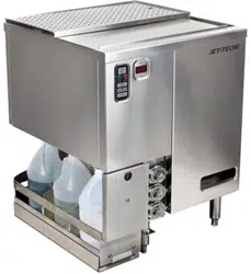
The glasswasher is shipped in one carton. Refer to the images on the opposite page to identify the following:
1. Main section
2. Drainboard insert
3. Drainboard pan
4. Sliding cover
5. Inner cover
utIlIty requIrements and connectIons
1. General plumbInG
(Hot and cold water
required)
a. Use 1/2" OD (or larger) copper to 3/8" FMPT adapter provided.
b. Minimum water pressure - 25 PSI.
c. Maximum water pressure - 100 PSI. Install water pressure regulator if line pressure is over
100 PSI. Water valve on unit has built-in strainer and flow control to provide consistent vol-
ume between 25 and 100 PSI.
d. Install separate water shut-off valve for each connection.
e. Unit has built-in air gaps - vacuum breakers NOT required.
2. hot water wash
a. Maximum temperature 150°F (66°C). Minimum supply temperature 130°F (54°C) to ensure
a minimum wash temperature of 120°F (49°C).
3. cold water rInse
a. No minimum cold water inlet temperature. Control module automatically tempers rinse
based on temperature setting (see Start-Up Instructions page 5, Step 5).
2. draIn
a. 1-1/2" tailpiece provided on unit.
b. Use open type floor drain for maximum drainage.
3. electrIcal
a. 120V, single phase, 60Hz, 6-foot grounded cord included.
b. A dedicated 15 amp circuit is recommended.
c. Power requirements - 3.5 amps.
4. deterGent
a. Extra heavy-duty non-foaming commercial liquid dish detergent required. Adjust to .30% con-
centration.
b. Consult The local chemical supplier to match detergent with local water conditions.
5. sanItIzer
a. Liquid chlorine bleach (sodium hypochlorite - 5.25% solution) adjusted to 50 PPM.
6. rInse aId
a. Liquid Rinse Aid adjusted for proper sheeting.
7. notes
a. In all cases, consult local plumbing, electrical, and health codes for regulations which may
not be consistent with the above.
b. Utilityconnectionsaremadeupfromtheooratthebottomoftheunitapproximately6"high.
c. A side notch located on the left side of the unit provides space for three one-gallon chemical
containers within the 24" x 24" footprint.
6. Conveyor
7. Spray box
8. Spray box gasket
9. Tank screen
10. Drain stopper
uncratInG and assembly InstructIons
11. Inlet screen
12. Scrap tray
13. Water inlets
14. Chemical inlets
assembly procedures:
1. Remove all packaging from the main section.
2. Remove plastic protective paper from all stainless steel parts.
3. Place glasswasher in position and level by adjusting the bottom portion of the stainless legs.
4. Make plumbing connections in accordance with utility requirements listed above.
5. Install chemical bottle rack accessory if ordered with unit. See page 10 for installation instructions.
Loading ...
Loading ...
Loading ...