Loading ...
Loading ...
Loading ...
BELT REPLACEMENT
_lk CAUTION:
Disconnect'spark plug wire from spark
plug before replacing V-belt.
• Move Blade Clutch Lever to the "DISENGAGED"
position.
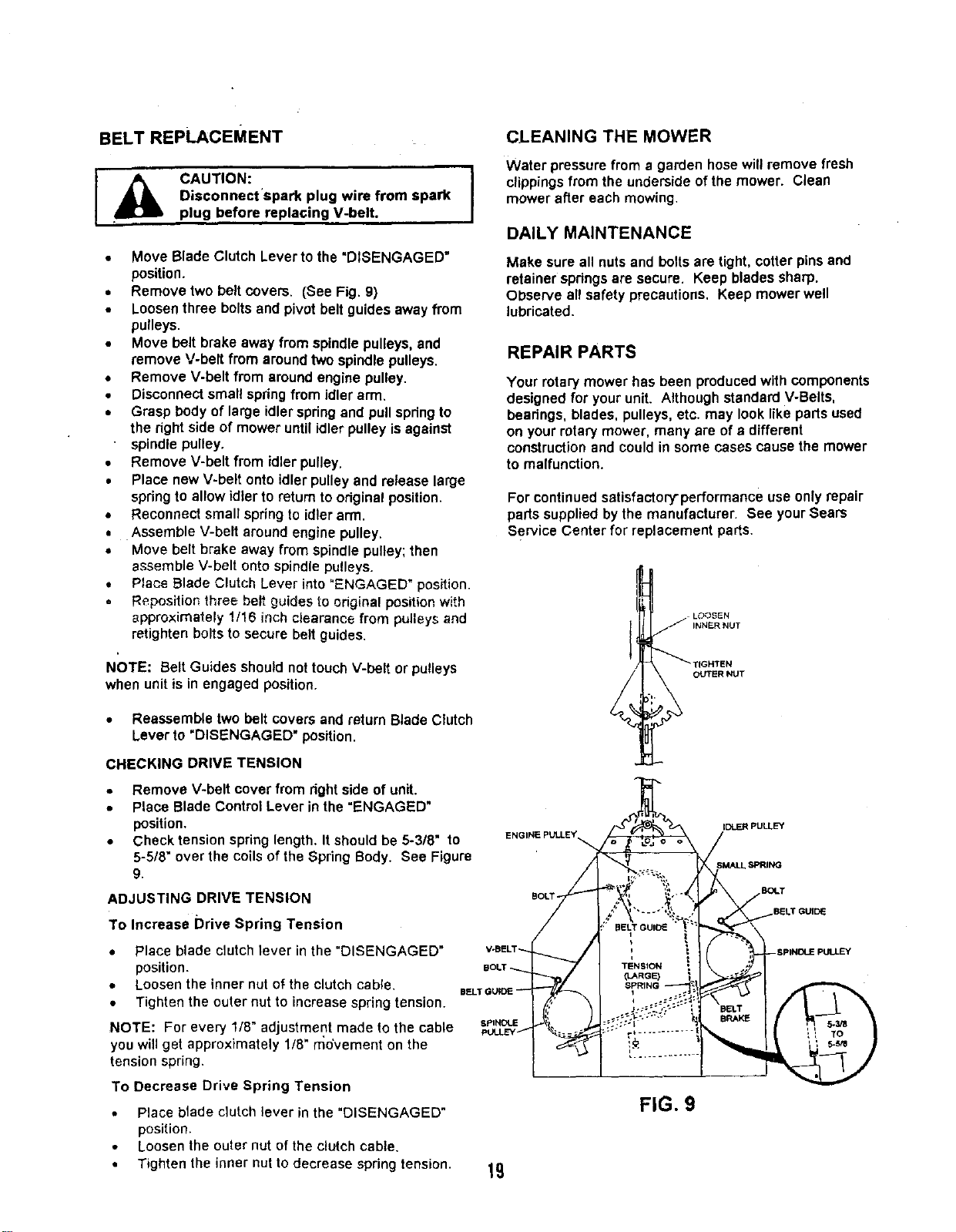
• Removetwo belt covers. (See Fig. 9)
• Loosenthree boltsand pivot belt guides away from
pulleys.
• Move belt brake away from spindlepulleys,and
remove V-belt from aroundtwo spindlepulleys.
• Remove V-belt from aroundengine pulley.
• Disconnectsmall springfrom idler arm.
• Grasp body of large idlerspringand pull springto
the right side of mower untilidler pulleyis against
spindle pulley.
• Remove V-belt from idler pulley.
• Place newV-belt onto idlerpulley and release large
springto allow idlerto return to originalposition.
• Reconnect small springto idlerarm.
• Assemble V-belt aroundengine pulley.
• Move belt brake away from spindlepulley;then
assemble V-belt ontospindlepulleys.
• P_aceBlade Clutch Lever into"ENGAGED" position.
Repositior_three belt guides to odginal position with
approximately 1/16 inch clearance from pulleys and
retighten bolts to secure belt guides,
NOTE: Belt Guides should not touchV-belt or pulleys
when unitis in engaged position.
• Reassembletwo belt covers and return Blade Clutch
Lever to "DISENGAGED" position.
CHECKING DRIVE TENSION
CLEANING THE MOWER
Water pressure from a garden hose will remove fresh
clippings from the underside of the mower. Clean
mower after each mowing.
DAILY MAINTENANCE
Make sure all nutsand boltsare tight, cotter pinsand
retainerspdngs are secure. Keep bladessharp.
Observe all safety precautions. Keep mower well
lubricated.
REPAIR PARTS
Your rotarymower has been produced with components
designedfor your unit. Although standard V-Belts,
bearings, blades, pulleys,etc. may looklike parts used
on yourrotarymower, many are of a different
constructionand couldin some cases causethe mower
to malfunction.
For continuedsatisfactory-performanceuse onlyrepair
partssupplied bythe manufacturer. See yourSears
Service Center for replacement parts.
I __ L_:<3SEN
INNER NUT
_T{GHTEN
OUTER NUT
• Remove V-belt cover from right side of unit.
• Place Blade Control Lever inthe"ENGAGED"
position.
• Check tension springlength. It shouldbe 5-3/8" to
5-518"overthe coilsofthe SpringBody. See Figure
9.
ADJUSTING DRIVE TENSION
To Increase Drive Spring Tension
BOLT -
IDLER PULLEY
SPRING
EUDq.T
• Place blade clutch lever in the "DISENGAGED"
position.
• Loosen the inner nut o_the clutch cable.
• Tighten the outer nut to increase spring tension.
NOTE: For every 1/8" adjustment made to the cable U',NDUE
yOUwill get approximately 1/8" movement on the
tension spring.
To Decrease Drive Spring Tension
• Place blade clutch lever in the "DISENGAGED"
position.
• Loosen the outer nut of the clutch cable.
• Tighten the inner nut to decrease spring tension.
19
FIG. 9
Loading ...
Loading ...
Loading ...