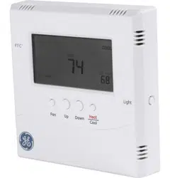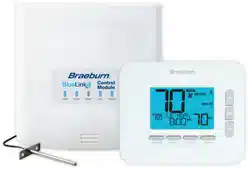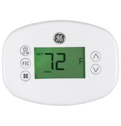

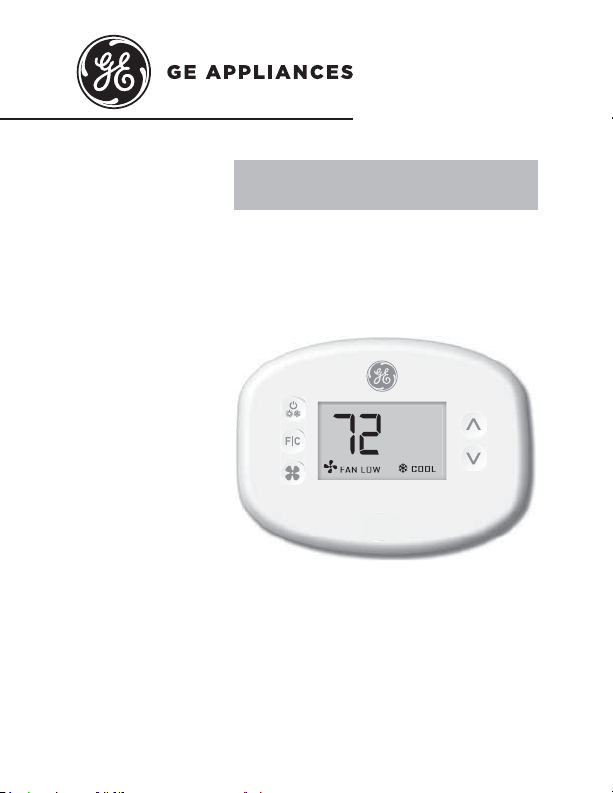
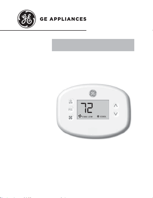
THERMOSTAT
Wireless Thermostat with two fan speeds
OWNER’S MANUAL &
INSTALLATION INSTRUCTIONS
RAK160W2
49-5000637 Rev. 0 05-22 GEA
F
2 49-5000637 Rev. 0
THANK YOU FOR MAKING GE APPLIANCES A
PART OF YOUR HOME.
Whether you grew up with GE Appliances, or this is
your first, we’re happy to have you in the family.
We take pride in the craftsmanship, innovation and
design that goes into every GE Appliances product,
and we think you will too.

49-5000637 Rev. 0 3
Table of Contents
Safety Information .................................................... 4
Before You Begin .......................................................5
Thermostat Installation ............................................ 7
Installing the Wireless Control card................................7
Wireless Installation .....................................................10
Wired Installation ..........................................................10
Thermostat Configuration ..................................... 11
Setting the clock ...........................................................12
Entering the room number ...........................................13
Configuring the Equipment Settings .............................14
Custom Energy Savings Settings ...................... 16
Using the Thermostat Settings Screens.......................17
01 – FAN CONTROL MODE ........................................18
02 – 1ST STAGE DIFFERENTIAL - HEAT ..................19
03 – 2ND STAGE DIFFERENTIAL - HEAT .................20
04 – 1ST STAGE DIFFERENTIAL - COOL .................21
07 – FORCED 2ND STAGE HEATING .......................22
17 – MINIMUM SET POINT .........................................23
18 – MAXIMUM SET POINT ........................................23
19 – TEMPERATURE CONTROL MODE ....................24
20 – AUTO CHANGEOVER SET POINT OFFSET
(DEAD BAND) ......................................................25
23 – TEMPERATURE CALIBRATION .........................26
Thermostat Maintenance ......................................27
Troubleshooting ........................................................28
Technical Specifications .......................................31
Limited Warranty ......................................................32
4 49-5000637 Rev. 0
Specifications.
WARNING
FIRE AND SHOCK HAZARD
• Always turn off power at the main power supply
before installing, cleaning or removing the
thermostat. Failure to do so could result in
electrical shock hazard.
• Do not use on voltages over 30 VAC. Higher
voltages will damage the thermostat and could cause
shock or fire hazard.
NOTICE
• All wiring must conform to local and national
electrical and building codes.
• Use this thermostat only as described in this manual.
Electrical rating: • 24 VAC (18–30 VAC)
• 1 amp maximum per terminal
• 4 amp maximum total load
Operating temperature range: 40°F–99°F (4°C–37°C)
System Configurations:
* 1 stage cool, 2 stage heat (heat pump/resistance heat)
1 stage cool, 1 stage heat (resistance heat)
Terminations: *R, C, W, Y, GH, GL, B for 2-stage heat
R, C, W, Y, GH, GL, for 1-stage heat
Wiring (for R & C if wiring for power): Maximum wiring
length is 66ft (20 meters) for AWG18
Maximum wiring length is 60ft (18 meters) for AWG20
*Default setting
IMPORTANT SAFETY INFORMATION
READ ALL INSTRUCTIONS BEFORE USING
49-5000637 Rev. 0 5
Before You Begin
• Determine the appropriate installation location for the
thermostat
The thermostat must not be installed near or on
metal structures or surfaces including metal air
ducting that may be in the wall.
0HWDOVWUXFWXUHVDQGVXUIDFHVVLJQL¿FDQWO\
reduce the range of the wireless signal.
A. Refer to the Zoneline Owner’s Manual to enable the
use of a wall thermostat. For AZ45/65 Series Models,
auxiliary mode 6 should be set to “6A”.
B. Zoneline output is 24VAC. Be sure the jumper on the
wireless control card is on the AC position – jumper
is connecting “R” and “C” (common) pins. This is the
default position.
6 49-5000637 Rev. 0
NETWORK INSTALLATION ONLY
NOTE: This section is not required unless the thermostats are
networked
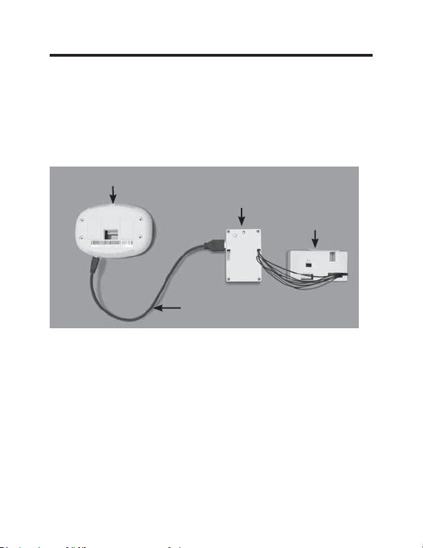
Pairing the Thermostat and the Control Card:
In case of Network Installation with online management, the
thermostat and the Control Card must be paired with a Network
Programmer specific to the property before the installation.
Note: Thermostat and Control Card are factory paired.
The thermostat and control card must not be powered during the
pairing procedure - remove batteries from the thermostat and unplug
the control card from the HVAC unit during the pairing procedure.
• Plug one programmer connector into the thermostat;
• Plug the other programmer connector into the control card.
• Push the black button on the programmer.
•
The red light on the programmer should turn on and remain
steadily lit.
•
If the red light on the programmer is blinking or is not steadily
lit, unplug the programmer from the thermostat and the control
card and repeat the steps above.
• Unplug the programmer from the thermostat and the control card.
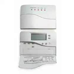
Thermostat
Network
Programmer
Programmer
Connector
Control
Card
49-5000637 Rev. 0 7
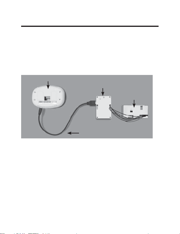
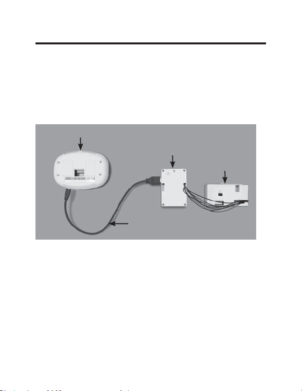
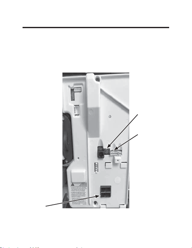
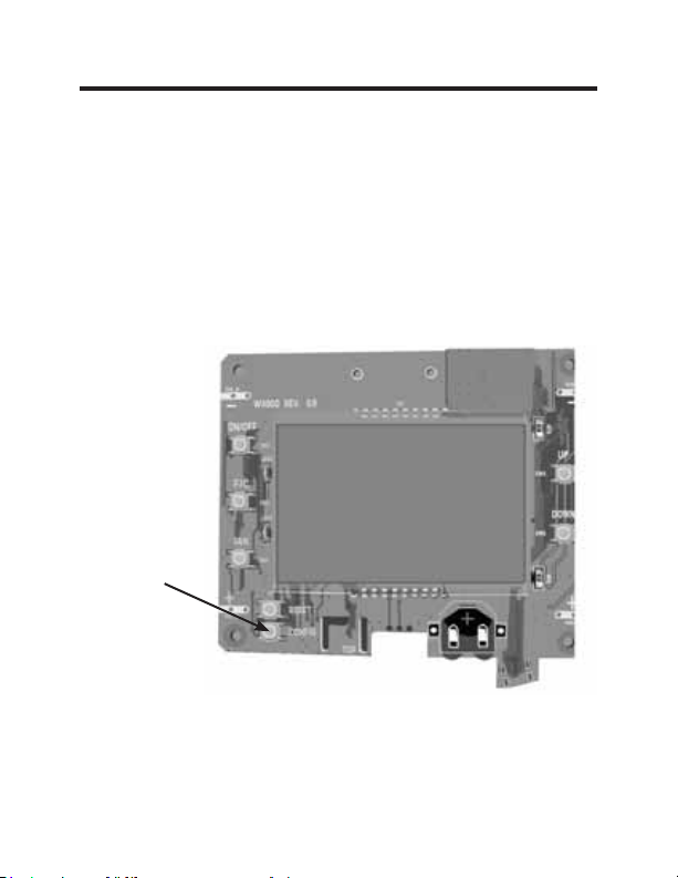
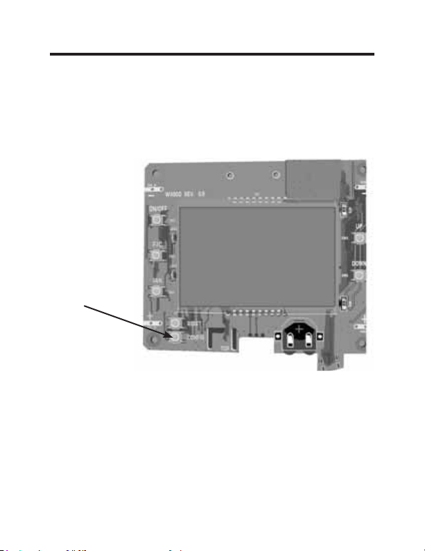
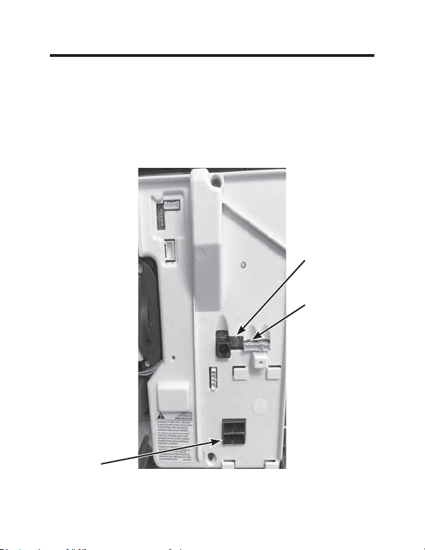
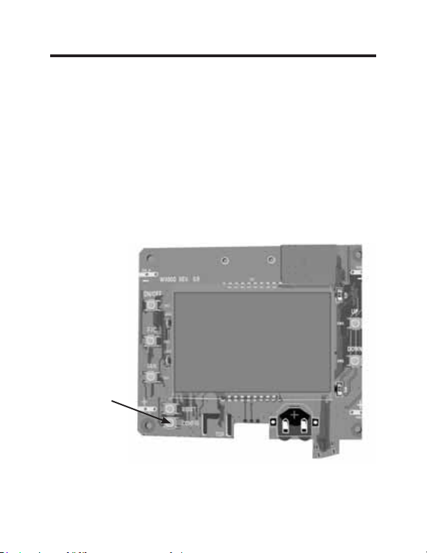
Thermostat Installation
Installing the Wireless Control Card
• Power off the Zoneline
• Insert the Control Card wiring harness into the thermostat
connection port on the front of the Zoneline control box cover.
AC input
Remote
Thermostat
Connection
Red Aux Set
Button
Image 1
8 49-5000637 Rev. 0
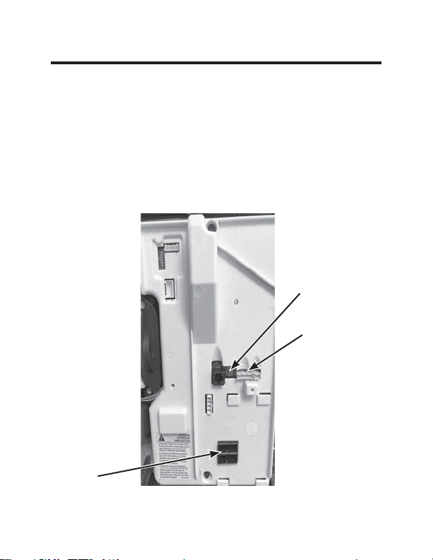
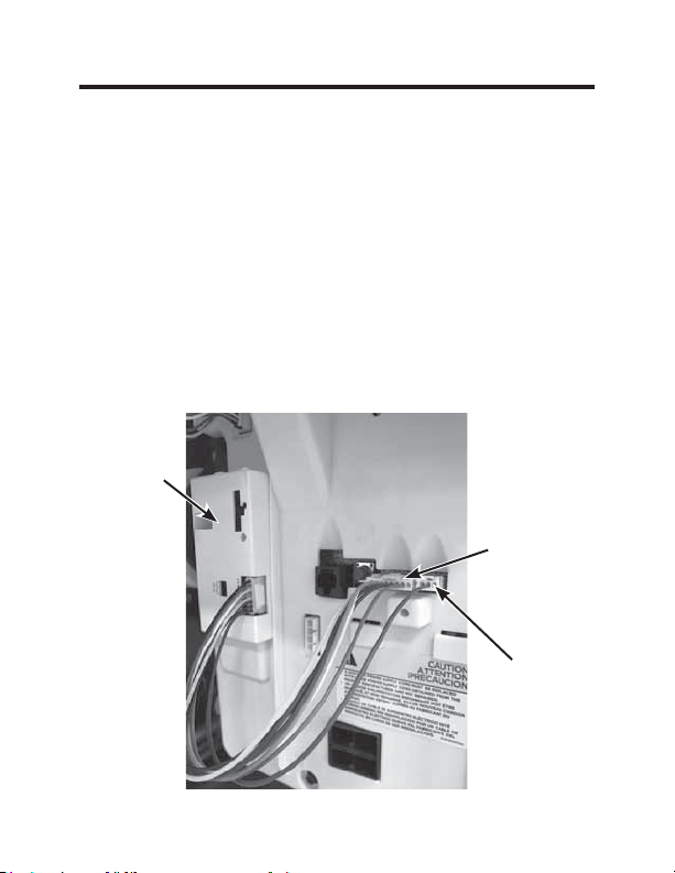
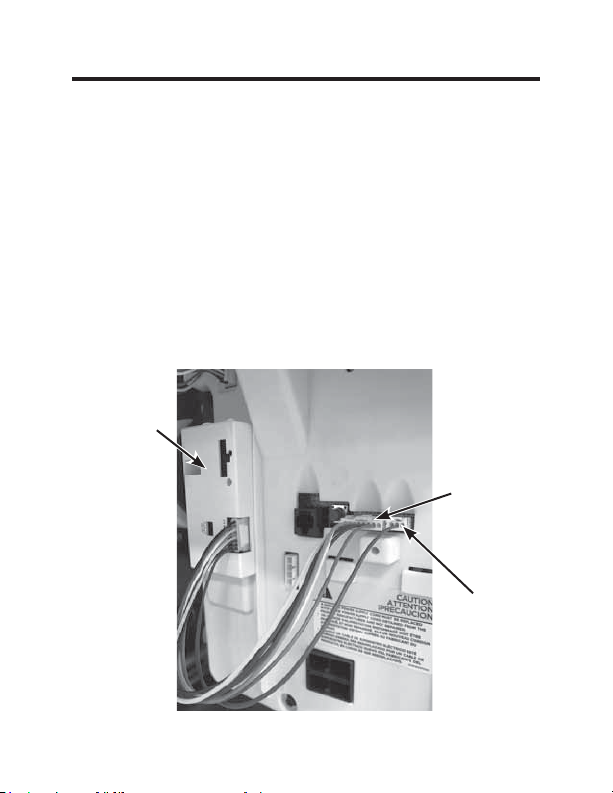
Thermostat Installation
Installing the Wireless Control Card (cont.)
• Using double sided tape, attach the control card to the Zoneline
control box cover (see image 2).
The wireless control card antenna must not be touching any metal
components of the hvac unit.
The wireless control card antenna must face the thermostat on the
wall and be oriented so that any metal parts of the Zoneline do not
obstruct the wireless communication to the thermostat and, in case of
a network installation, to other wireless control cards and the server.
The wireless control card must not be placed in the Zoneline
condensation pan and must be mounted so it cannot fall into the
condensation pan.
• For wired applications, join the common and 24VAC wires with
any code-approved low voltage field supplied connection method.
CDC/
Occupancy
Note: This
connector is
not required for
RAK160W2
Remote
Thermostat
Connection
Control
Card
Image 2
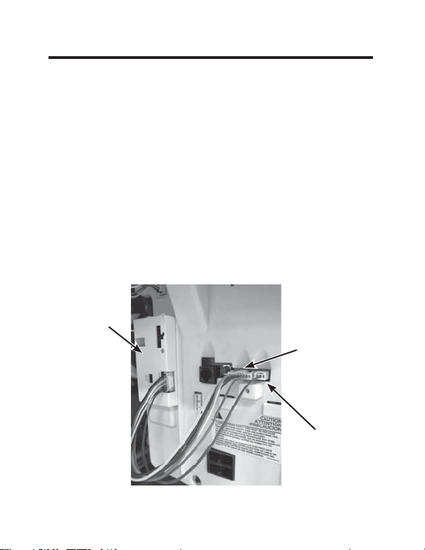
49-5000637 Rev. 0 9
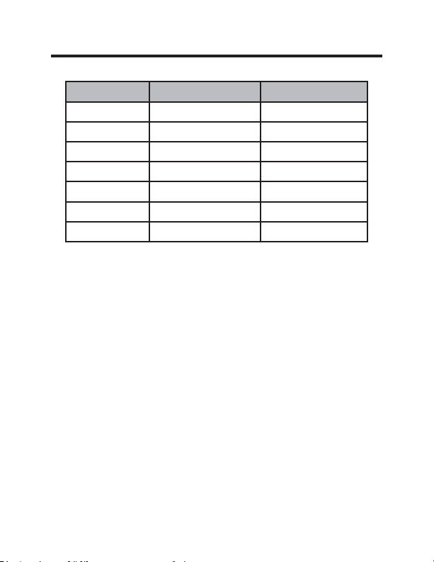
Thermostat Installation
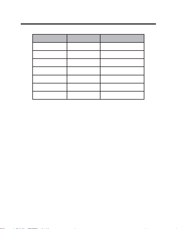
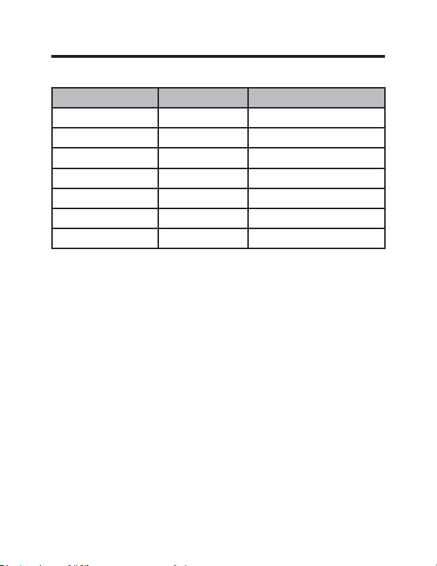
Wire Color Terminal Letter Terminal Connection
Black C Common
Red R 24V
Yellow Y Compressor
White W Heat
Orange O or B Reversing Valve
Green GH Fan High
Purple GL Fan Low
NOTE: If the PTAC unit has only one (1) fan speed,
connect both fan control wires – Green and Purple –
to the fan terminal (G).
Wiring Table – 24V AC
10 49-5000637 Rev. 0
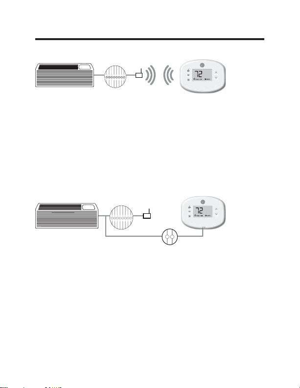
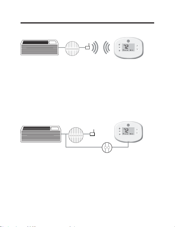
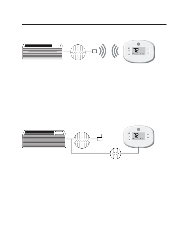
Thermostat Installation
Wireless Installation
GH OB W R Y C
AUX
GL
F
Mounting the thermostat to the wall
• Remove the thermostat cover;
• Use the supplied wall anchors and mounting screws to
secure the thermostat to the wall;
• Insert two (2) AA-cell batteries (not supplied) into the
thermostat battery compartment;
• Follow the “Thermostat Configuration” instructions
starting on page 11.
• Replace the thermostat cover and screw in the locking
screw.
Wired Installation
GH OB W R Y C
AUX
GL
R C
F
Mounting the thermostat to the wall
• Connect R & C from HVAC unit to the corresponding
wires on the harness by splicing 24VAC and common
wires from the thermostat into the 24VAC and common
wires to the zoneline.
• Remove the thermostat cover;
• Use the supplied wall anchors and mounting screws to
secure the thermostat to the wall;
• Follow the “Thermostat Configuration” instructions
starting on page 11.
• Replace the thermostat cover and screw in the locking
screw.
49-5000637 Rev. 0 11
Thermostat Configuration
Once the thermostat is powered, thermostat configuration
settings will appear on the thermostat screen.
In order to properly operate the HVAC unit:
• Set the thermostat clock
• Enter the room number
• Configure the equipment settings
The thermostat configuration screens have a 30-second
time-out. If no action is taken within thirty (30) seconds, the
thermostat will exit configuration settings.
NOTE: You can
access Thermostat
Configuration settings at
any time by pressing the
“Configuration” button.
NOTE: If the
thermostat is connected to a network, the settings
configured online will be applied.
12 49-5000637 Rev. 0
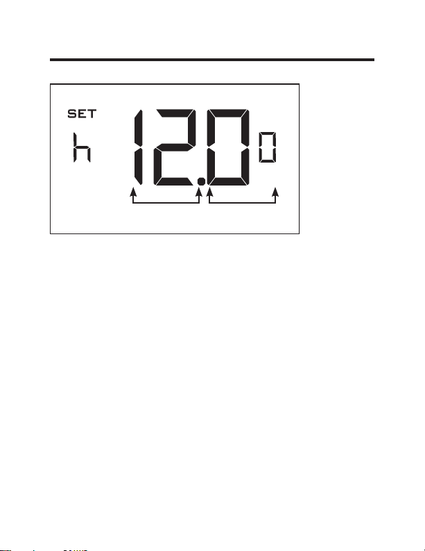
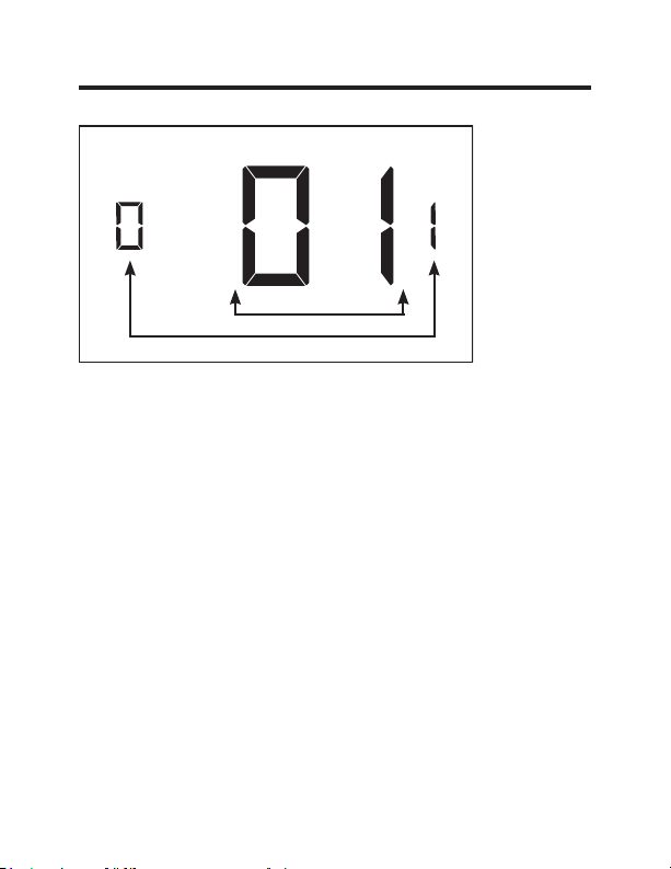
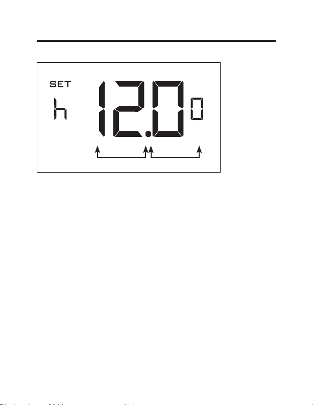
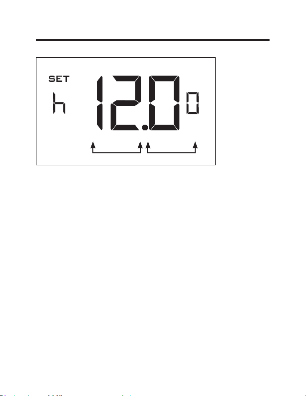
Thermostat Configuration
Setting the thermostat clock
Set the thermostat clock to current time in 24h (Military Time)
format.
• Use the “Up” and “Down” buttons to set the hours
• Press the “Fan” button to advance to the minutes setting
• Use the “Up” an “Down” buttons to set the minutes
• Press the “F/C” button to advance to the next menu
Setting the clock correctly is crucial for proper operation of
the thermostat.
NOTE:
The thermostat clock will need to be reset each time
the batteries are replaced.
Hours
Minutes
49-5000637 Rev. 0 13
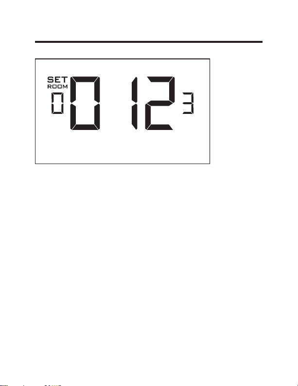
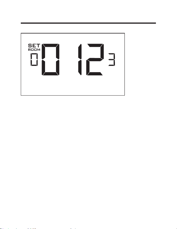
Thermostat Configuration
Entering the room number
Enter the room number by changing the digits on the screen.
Leading zeros “0” preceding other digits will be ignored, i.e.
Room number “123” should be entered as “00123”.
• Use the “Up” and “Down” buttons to change the digit;
• Press the “Fan” button to advance to the next digit;
• Press the “F/C” button to advance to the next menu;
Entering the room number correctly is crucial for proper
operation of networked systems.
14 49-5000637 Rev. 0
Thermostat Configuration
Configuring the Equipment Settings
• Use the “Up” and “Down” buttons to change the value of
each setting. Reference chart below for options.
• Press the “Fan” button to advance to the next setting.
• Press the “Power” button to save the Thermostat
Configuration and start using the thermostat.
Value Compressor Type Electric Heat Reversing Valve Fan Speed
0 No Compressor
No Electric
Heat
O/B Contact is
energized to cool
N/A
1 Heat Pump*
Electric
Heat*
O/B Contact is en-
ergized to heat*
One Fan
Speed
2 Air Conditioner N/A N/A
Two Fan
Speeds*
3N/A
Three Fan
Speeds
* Indicates default setting
NOTE: If the Zoneline is an AZ45 or AZ95E model, change
the compressor type to a 2.
Compressor
Type
Electric
Heat
Reversing
Valve
Fan
Speed

15 49-5000637 Rev. 0
Thermostat Configuration
Testing the thermostat
Following the thermostat configuration, test if the thermostat
is controlling the Zoneline unit.
• Press the “Power” button to turn the thermostat ON;
• Press the “Down” button to change the temperature set
point below the current room temperature to confirm that
the thermostat initiates air conditioning.
• Press the “Up” button to change the temperature set point
above the current room temperature to confirm that the
thermostat initiates heating.
• Change the fan speed by touching the “Fan” button to test if
the thermostat is controlling the fan speed.
49-5000637 Rev. 0 16
Custom Settings
This thermostat comes preprogrammed to use a custom
energy setting. To change any of these presets, follow the
instructions below.
Accessing the Thermostat Settings
With the thermostat turned on, press and hold the
“Configuration” button until the first thermostat settings screen
appears. The thermostat must be turned on to access the
thermostat settings.
³&RQ¿JXUDWLRQ´EXWWRQ
NOTE: If the thermostat is connected to a network, the
settings configured online will be applied.
• Use the “Up” and “Down” buttons to change the setting;
• Press the “F/C” button to advance to the next setting;
• Press the “Fan” button to return to the previous setting;
• Press the “Power” button to save and exit thermostat
settings.
17 49-5000637 Rev. 0
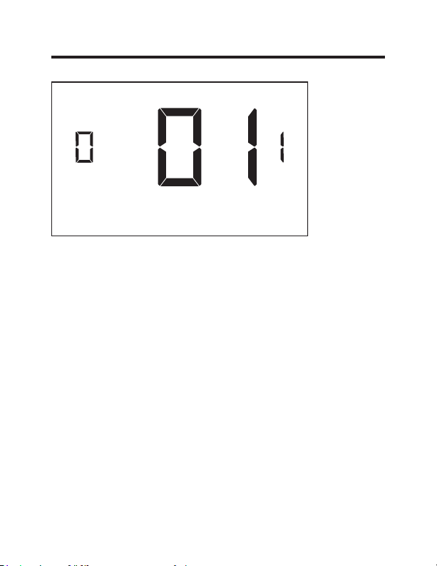
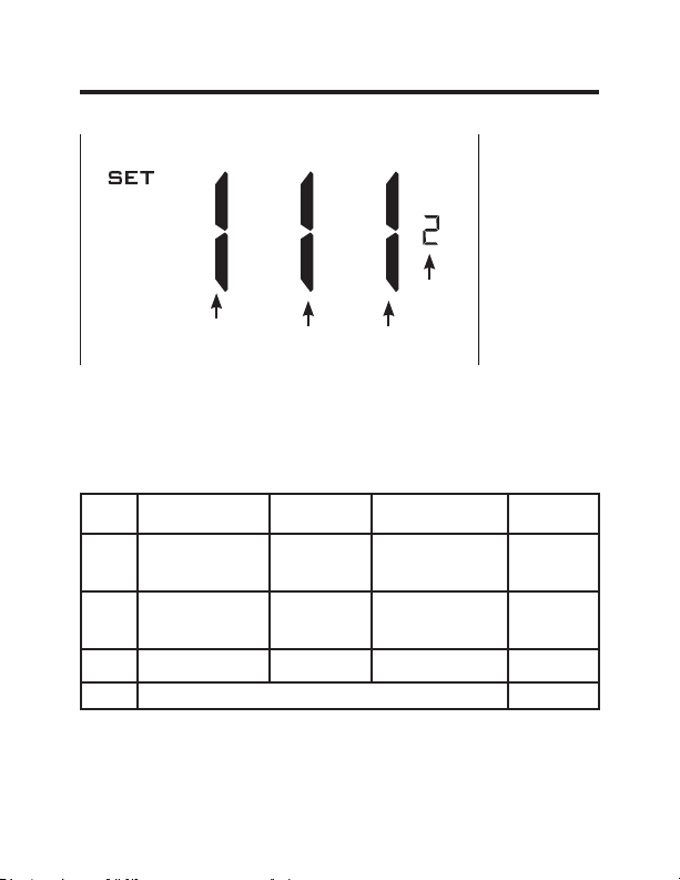
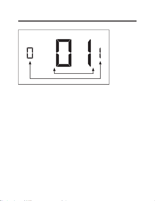
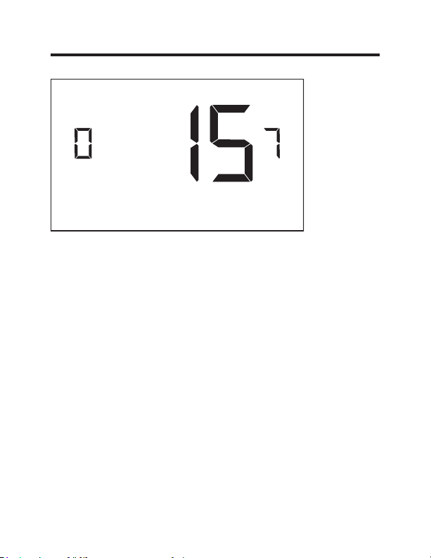
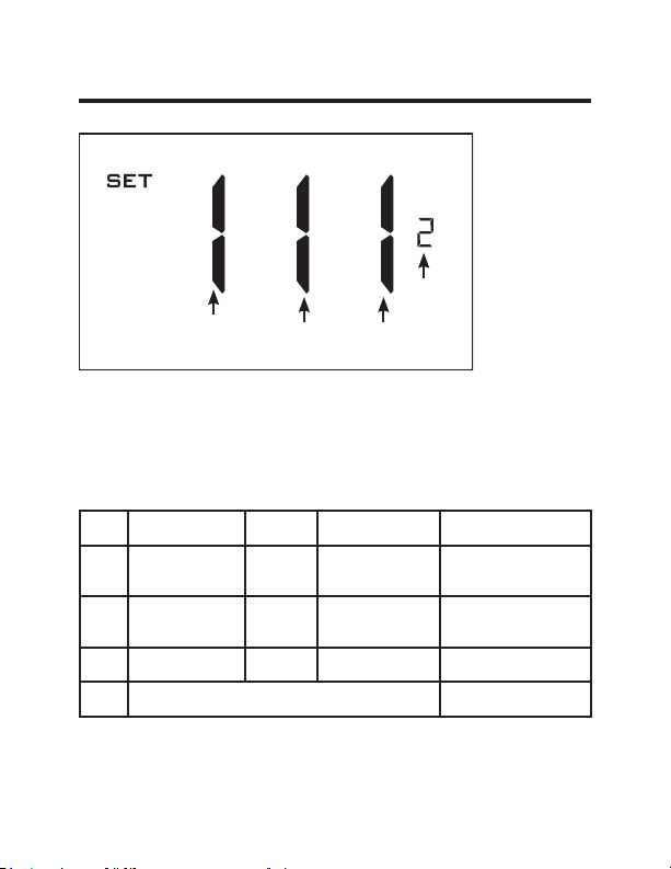
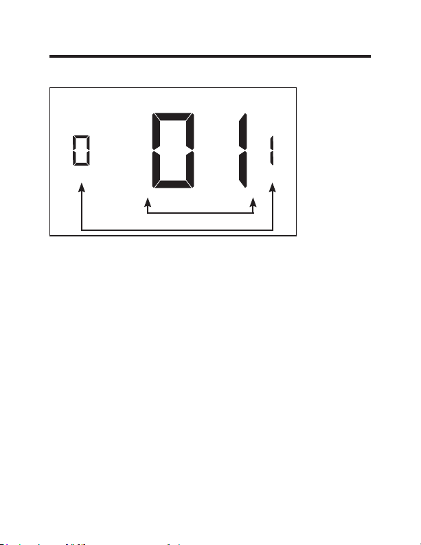
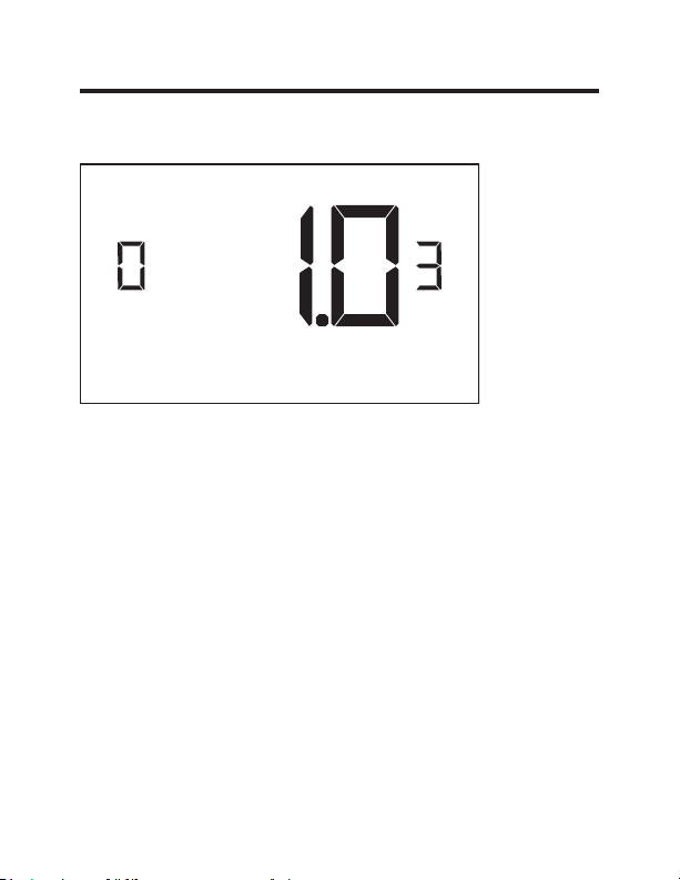
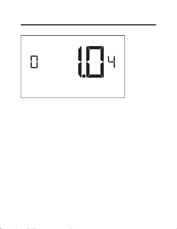
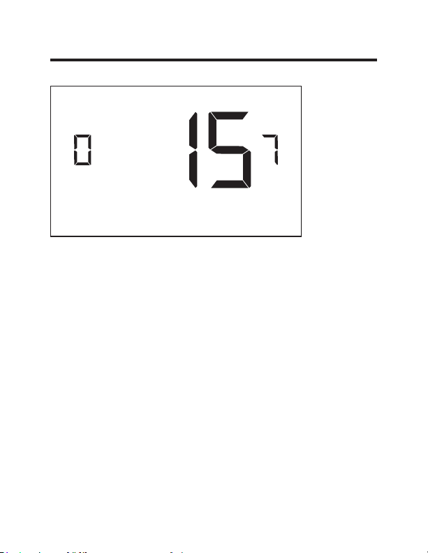
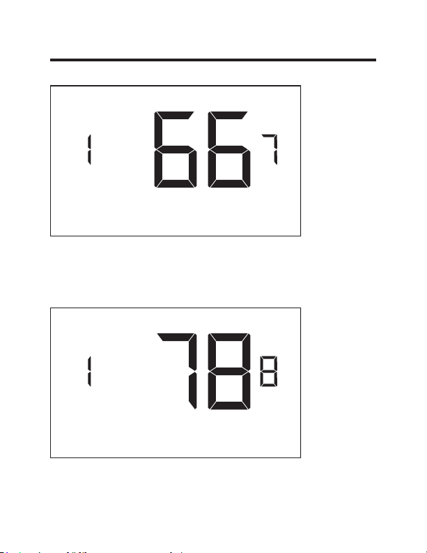
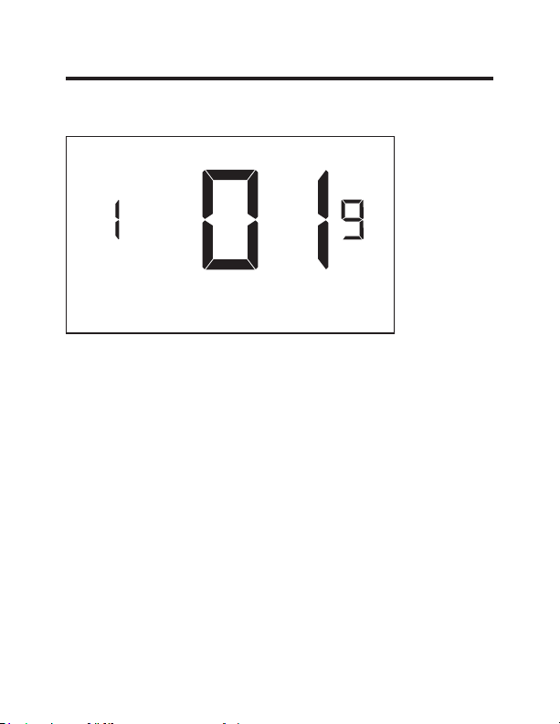
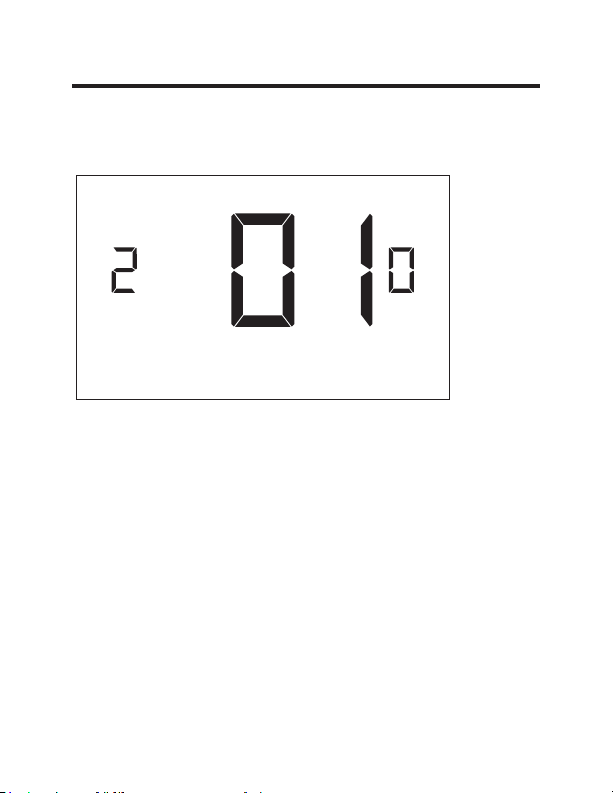
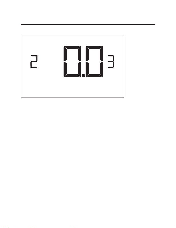
Custom Settings
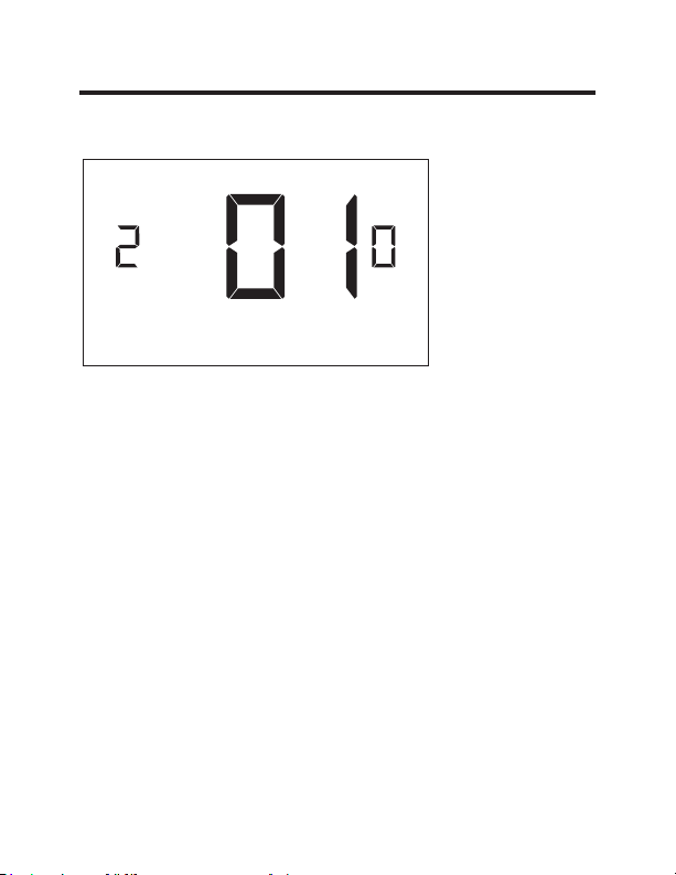
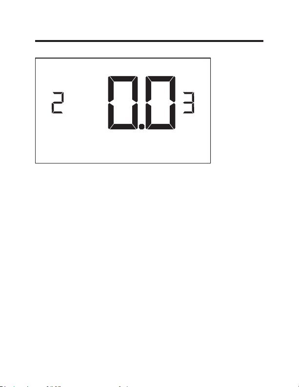
Using the Thermostat Settings Screens
• Use the “Up” and “Down” buttons to change the setting.
• Press the “F/C” button to advance to the next setting.
• Press the “Fan” button to return to the previous setting.
• Press the “Power” button to save and exit thermostat
settings.
The above is a representation of how to read the
digits on the thermostat screen.
Setting Value
Screen Number
49-5000637 Rev. 0 18
Custom Settings
01 – FAN CONTROL MODE
Select Fan Control Mode:
00 - MANUAL - guest can select automatic or continuous
fan mode.
01* - AUTOMATIC - fan runs only when there is a
demand for heating or air conditioning.
* Indicates default setting.

19 49-5000637 Rev. 0
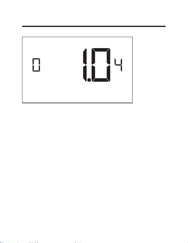
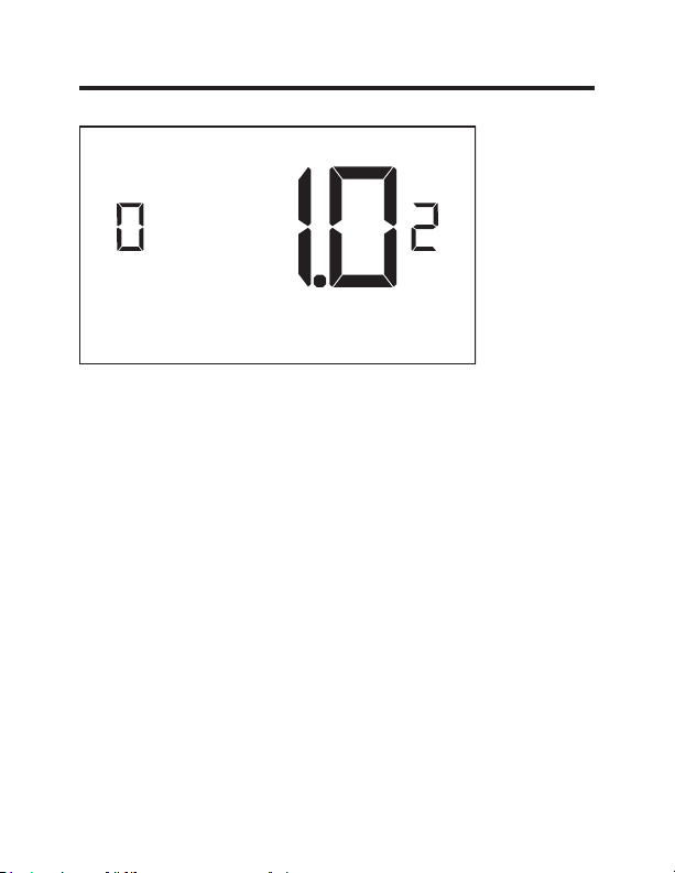
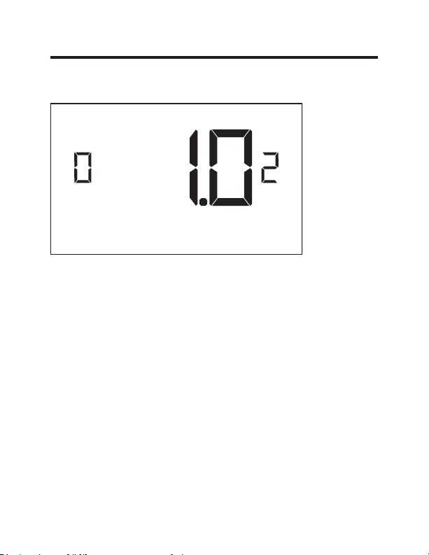
Custom Settings
02 – 1ST STAGE DIFFERENTIAL - HEAT
(0.2°F - 3.0°F; 1.0°F* default setting) Select the number
of degrees** the thermostat has to sense between the
automatic changeover temperature for heat and the room
temperature before a call for the 1st stage heating is
initiated.
** above the dead band offset (refer to page 25)

49-5000637 Rev. 0 20
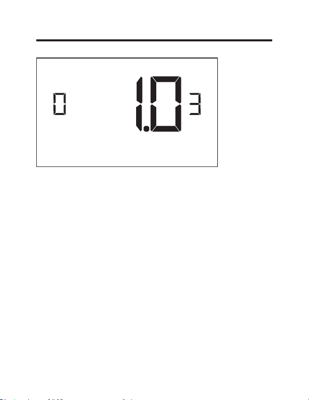
Custom Settings
03 – 2ND STAGE DIFFERENTIAL - HEAT
(1.0°F - 2.0°F; 1.0°F* default setting) Select the difference
between 1st stage heating and 2nd stage heating
initiation.
21 49-5000637 Rev. 0
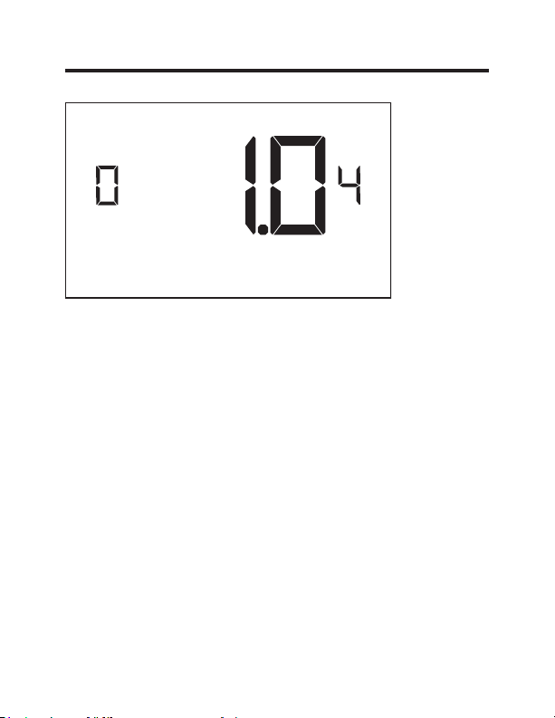
Custom Settings
04 – 1ST STAGE DIFFERENTIAL - COOL
(0.2°F - 3.0°F; 1.0°F* default setting) Select the number
of degrees** the thermostat has to sense between the
automatic for cool and the room temperature before a call
for the 1st stage cooling is initiated.
**below the dead band offset (refer to page 25)

22 49-5000637 Rev. 0
Custom Settings
07 – FORCED 2ND STAGE HEATING
(00 - 60; 15* default setting) Select a number of minutes
1st stage heating will run before 2nd stage heating
is automatically initiated if the guest set point is not
reached and the 2nd stage heating is not initiated through
differential settings.
This feature allows automatically turning on 2nd stage
heating to avoid excessive compressor use.
Set to 00 to disable the feature.
23 49-5000637 Rev. 0
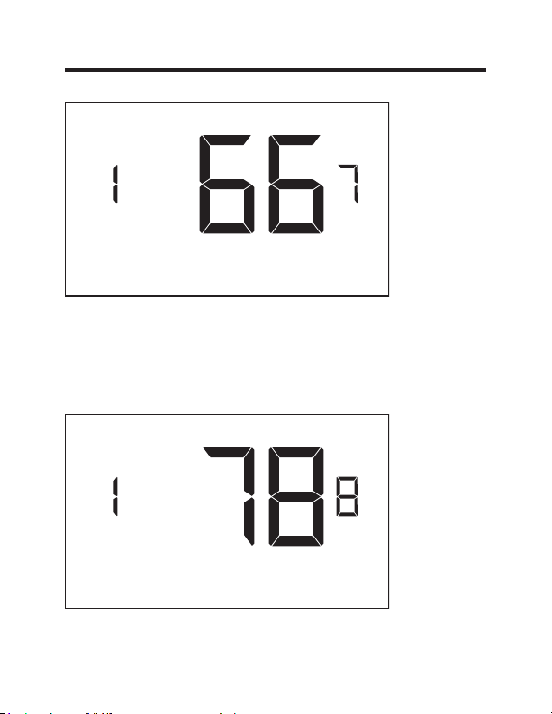
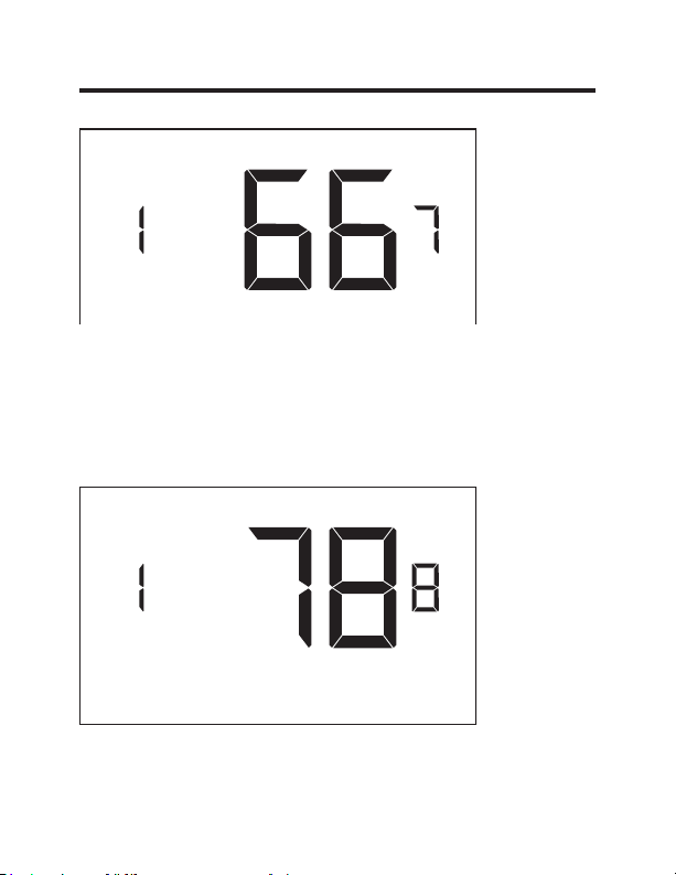
Custom Settings
17 – MINIMUM SET POINT
(64°F - 84°F; 66°F* default setting) Select the minimum
set point in °F that a guest can select.
18 – MAXIMUM SET POINT
(60°F - 82°F; 78°F* default setting) Select the maximum
set point in °F that a guest can select.
24 49-5000637 Rev. 0
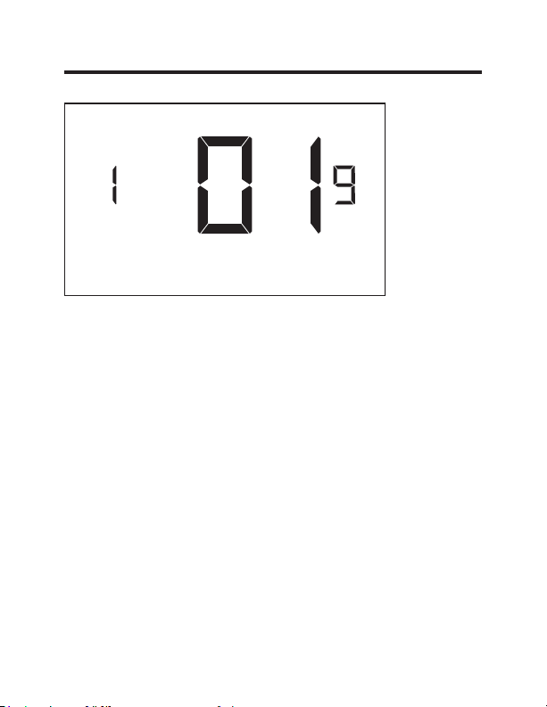
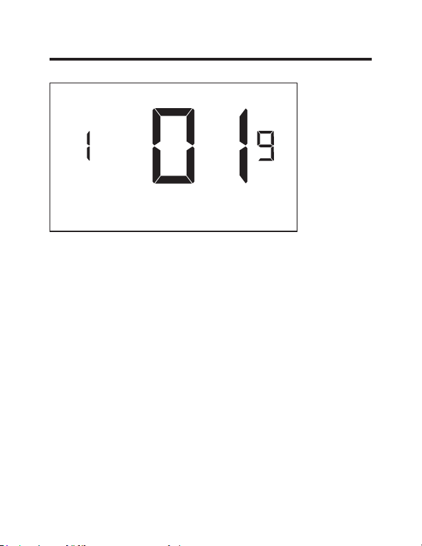
Custom Settings
19 – TEMPERATURE CONTROL MODE
Select Temperature Control Mode:
00 - MANUAL - Allows users to select HEAT only or
COOL only temperature control mode to maintain the
room temperature.
01* - AUTOMATIC - Thermostat automatically turns on
heating or air conditioning to maintain the room
temperature at the selected temperature set point.
* Indicates default setting
25 49-5000637 Rev. 0
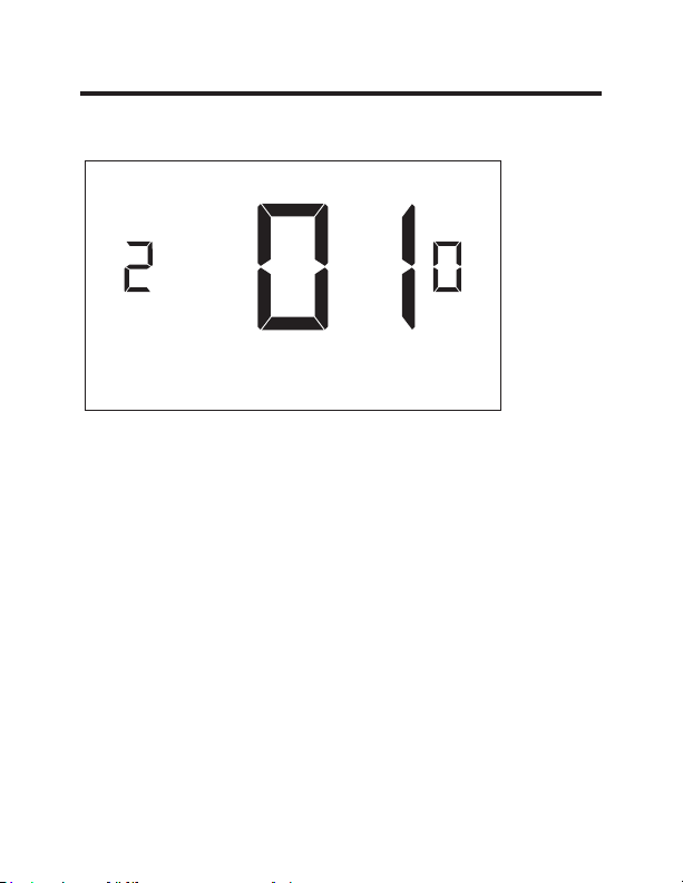
Custom Settings
20 – AUTO CHANGEOVER SET POINT OFFSET
(DEAD BAND)
(00°F - 05°F; 01°F* default setting) Select the difference
between the guest-selected set point and the heat and
the cool set point when the thermostat is in the automatic
temperature control mode.
This value plus the 1st stage differential defined in
settings 02 and 04, defines the temperature at which the
thermostat would automatically change heating/cooling
modes.
This feature allows adjusting the dead band between the
heat and the cool set points in automatic changeover
mode in order to avoid the system from bouncing back
and forth between heating and cooling under normal
operating conditions.

26 49-5000637 Rev. 0
Custom Settings
23 – TEMPERATURE CALIBRATION
(-5.0°F - 5.0°F; 0.0°F* default setting) Calibrate the
temperature display: +/- 5.0°F

27 49-5000637 Rev. 0
Thermostat Maintenance
Replacing Thermostat Batteries
The low battery indicator will be displayed on the
thermostat screen when it is necessary to replace batteries
in the thermostat.
Under normal operating conditions, new brand-name
alkaline batteries will last for a period of approximately one
(1) year.
Please replace batteries every twelve (12) months to
ensure continuous thermostat operation.
To replace thermostat batteries:
•
Remove the thermostat cover;
•
Replace the two (2) AA-cell batteries (not-supplied);
•
Replace the thermostat cover;
•
Follow the “Thermostat Configuration” instructions to set
the thermostat clock;
•
Press the “Power” button to start using the thermostat;
NOTE: The thermostat maintains all the “Thermostat
Configuration” settings in a non-volatile memory. There
is no need to configure the thermostat again after battery
replacement.
NOTE: While batteries are not required in a wired
installation, batteries should be installed to prevent
re-configuring the time on the thermostat if a power failure
occurs.

49-5000637 Rev. 0 28
Troubleshooting
Error Codes
ERR1 - Thermostat Temperature Sensor Hardware Defect
ERR2 - Thermostat Radio Hardware Defect
ERR3 - Thermostat Radio Software Defect
ERR4 - No link with the Wireless Control Card
ERR5 - Thermostat Memory Defect
NOTES:
For ERR1, ERR2, ERR3, and ERR5, call GE Appliances
service. (Phone number located in Limited Warranty
section on page 32.
For ERR4, reset the configurations starting on page 5.

29 49-5000637 Rev. 0
Troubleshooting
The thermostat is not controlling the HVAC unit.
Check if the HVAC unit is set to “External Thermostat”
(Class 2) mode. Refer to Zoneline Owner’s Manual, Aux
settings.
Verify the status of the red light on the Wireless Control
Card.
•
The red light is off
The Wireless Control Card is not powered. Verify that
the Wireless Control Card is properly wired to the HVAC
unit-specifically make sure that the RED and the BLACK
wire are properly connected.
•
If the red light is blinking with one (1) flash.
The Wireless Control Card is powered but it is not
communicating with the thermostat, turn the thermostat
off and on to re-initiate the linking procedure.
In case of a Network Installation, re-link the thermostat
and the Wireless Control Card with the Network
Programmer.
•
The red light is blinking with three (3) flashes.
The Wireless Control Card is communicating with the
thermostat. Verify that the Wireless Control Card is
properly wired to the HVAC unit and that equipment
settings on a thermostat - compressor type, electric heat
and reversing valve - are properly configured.

49-5000637 Rev. 0 30
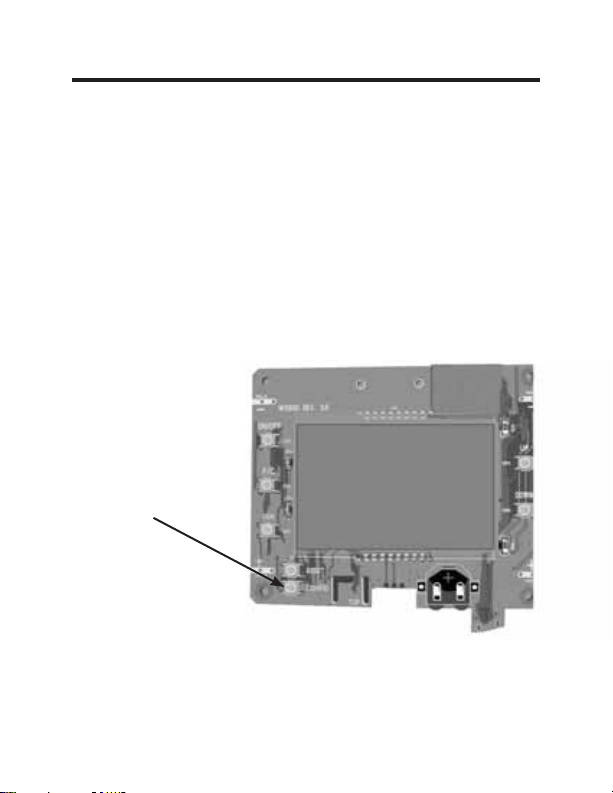
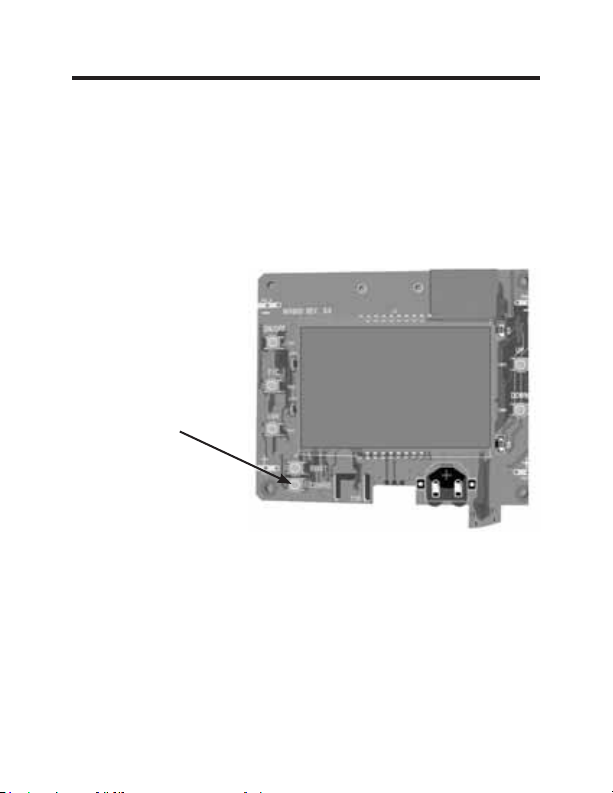
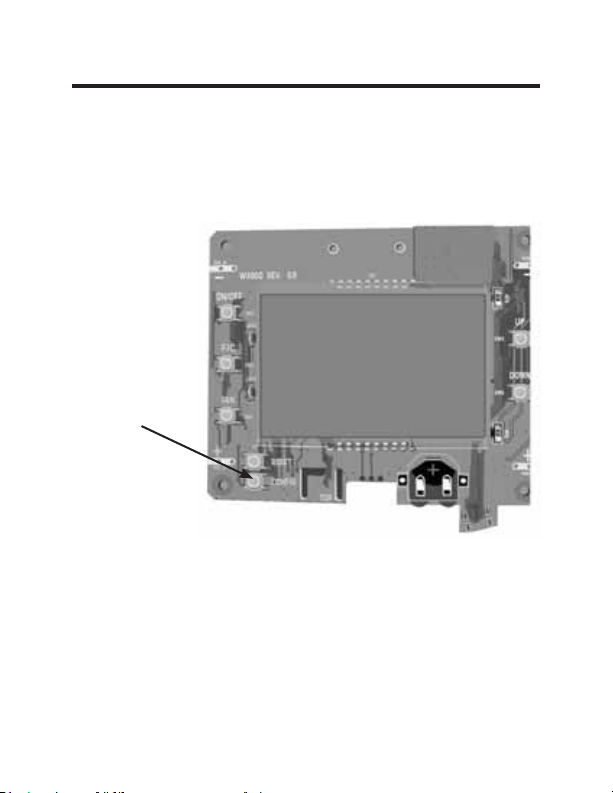
Troubleshooting
Initiating a Master Reset
If there are reported errors or configuration issues, the
user may master reset the thermostat to its default
parameters.
Procedure:
•
Remove the faceplate of the thermostat
•
Power down the thermostat by either removing the
batteries or cutting power to the thermostat.
•
While the thermostat is powered off, press and hold the
“config” button located on the control board inside the
thermostat.
• Restore power to the thermostat by reinstalling the
batteries.
• Once the screen lights up,
release the “config” button.
•
If the master reset was successful, the thermostat will
display “12:00”,indicating all settings will be reset to
default and the thermostat needs to be re-configured.
Please see “configuring thermostat” in the manual on
page 11.
Contact GE Appliances technical support at
1-844-GE4-PTAC option 1 (or 844-434-7822) if the issues
are not resolved.
31 49-5000637 Rev. 0
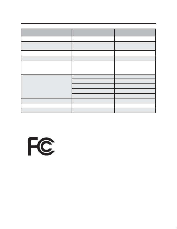
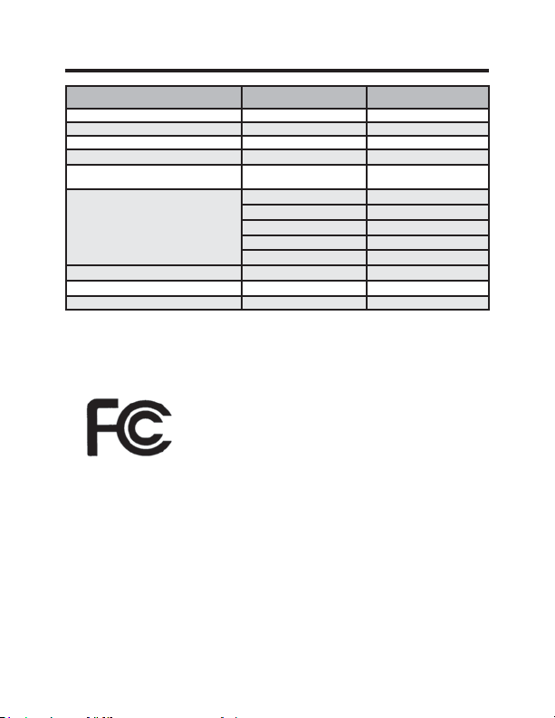
Technical Specifications
Thermostat Wireless Control Card
Case Dimensions (Imperial) 4.015 x 5.5118” x 0.925” 3.875” x 2.125” x 0.75”
Case Dimensions (Metric) 102mm x 140mm x
23.5mm
98mm x 54mm x 19mm
Screen Dimensions (Imperial) 3.625” x 2.125” N/A
Screen Dimensions (Metric) 92mm x 54mm N/A
Operating Voltage 3V DC - 2 “AA” Cell Bat-
teries OR(Optional) 24V
AC/DC
24V AC/DC
Control Outputs Fan High (GH)
Fan Low (GL)
Compressor (Y)
Heat Pump (OB)
Electric Heat (W2)
Wireless Frequency 900MHz 900MHz
Temperature Accuracy ±1°F N/A
FCC ID XEYWX XEYV8ACCC
FCC STATEMENT
This device complies with part 15 of the
fcc rules. Operation is subject to the
following two conditions: (1) this device
may not cause harmful interference, and
(2) this device must accept any inter-
ference received, including interference that may cause
undesired operation.
Pursuant to part 15.21 of the FCC rules, any changes or
PRGL¿FDWLRQVWRWKLVHTXLSPHQWQRWH[SUHVVO\DSSURYHGE\
GE Appliances may void the user’s authority to operate
the equipment.
32 49-5000637 Rev. 0
What GE Appliances Will Not Cover:
Ŷ Service trips to your location.
Ŷ Improper installation. If you have an installation problem, contact your installer.
You are responsible for providing adequate electrical connections to the product.
Ŷ Failure of the product resulting from modifications to the product or due to
unreasonable use, including failure to provide reasonable and necessary
maintenance.
Ŷ
In commercial locations, labor necessary to move the unit, after it has been initially
installed, to a location where it is accessible for service by an individual technician;
or, if the instructions included in this manual have been disregarded.
Ŷ
Replacement of location fuses or the resetting of circuit breakers.
Ŷ Damage to the product caused by improper power supply voltage, accident, fire,
floods or acts of God.
Ŷ Incidental or consequential damage caused by possible defects with this
thermostat.
THERMOSTAT LIMITED WARRANTY
For The Period Of: GE Appliances Will Replace:
One Year Full Replacement of the thermostat which fails
From the date of the due to a defect in materials or workmanship.
original purchase
Staple your receipt here.
Proof of the original purchase date is needed to validate the warranty.
This limited warranty is extended to the original purchaser and any succeeding owner for
products purchased for use within the USA and Canada. In Alaska, the limited warranty
excludes the cost of shipping or service calls to your site.
Some states or provinces do not allow the exclusion or limitation of incidental or consequential
damages. This limited warranty gives you specific legal rights, and you may also have other
rights which vary from state to state or province to province. To know what your legal rights are,
consult your local, state or provincial consumer affairs office or your state’s Attorney General.
Warrantor: GE Appliances, Louisville, KY 40225
EXCLUSION OF IMPLIED WARRANTIES—
Your sole and exclusive
remedy is product exchange as provided in this Limited Warranty. Any implied
warranties, including the implied warranties of merchantability or fitness for a
particular purpose, are limited to one year or the shortest period allowed by law.
For help with thermostat troubleshooting, call 1-844-GE4-PTAC option 1
(or 844-434-7822)
Thermostat sans fil avec deux vitesses de ventilateur
49-5000637 Rev. 0 05-22 GEA
THERMOSTAT
Manuel Du Propriétaire Et
Instructions D’installation
RAK160W2
F
2 49-5000637 Rev. 0
MERCI D’AVOIR INTÉGRÉ GE APPLIANCES
DANS VOTRE FOYER.
Que vous ayez grandi avec GE Appliances ou que
ce soit votre premier achat, nous sommes heureux
de vous accueillir dans notre famille.
Nous sommes fiers de nos artisans, de l’innovation et
de la conception faisant partie de chaque produit GE
Appliances et nous croyons que vous le serez aussi.

49-5000637 Rev. 0 3
Table des matières
Renseignements concernant la sécurité ....................... 4
Avant de commencer ...................................................................5
Installation du thermostat ........................................................... 7
Installation de la carte de commande sans fil ...................................7
Installation sans fil ............................................................................ 10
Installation câblée ........................................................................... 10
Configuration du thermostat .................................................. 11
Réglage de l’horloge ........................................................................ 12
Inscription d’un numéro de pièce .................................................... 13
Configuration des réglages d’équipement ..................................... 14
Réglages personnalisés d’économies d’énergie .......... 16
Utilisation des écrans de réglages du thermostat.......................... 17
01 – MODE DE COMMANDE DU VENTILATEUR ......................18
02 – 1RE PHASE DIFFÉRENTIELLE– CHAUFFAGE ................. 19
03 – 2E PHASE DIFFÉRENTIELLE– CHAUFFAGE ................... 20
04 – 1RE PHASE DIFFÉRENTIELLE– CLIMATISATION ...........21
07 – 2E PHASE DE CHAUFFAGE À AIR PULSÉ .......................22
17 – VALEUR DE CONSIGNE MINIMUM .................................... 23
18 – VALEUR DE CONSIGNE MAXIMUM ...................................23
19 – MODE DE CONTRÔLE DE TEMPÉRATURE ..................... 24
20 – COMMUTATION AUTOMATIQUE DU DÉCALAGE DE LA
VALEURDE CONSIGNE (ZONE MORTE) ........................... 25
23 – ÉTALONNAGE DE TEMPÉRATURE ...................................26
Entretien du thermostat ........................................................... 27
Dépannage ..................................................................................... 28
Spécifications ............................................................................... 31
Garantie limitée ........................................................................... 32
4 49-5000637 Rev. 0
Spécifications
AVERTISSEMENT
RISQUE D’INCENDIE ET D’ÉLECTROCUTION
• Veillez toujours à mettre l’alimentation électrique hors
tension depuis la source d’alimentation électrique
principale avant d’installer, de nettoyer ou de retirer le
thermostat. La désobéissance à ces directives représente
un risque d’électrocution.
• N’utilisez pas de tension supérieure à 30 VCA. Une tension
plus élevée endommagera le thermostat et causera un risque
d’électrocution ou d’incendie.
AVIS
• Tout le câblage doit être conforme aux Codes d’électricité
locaux, nationaux et aux Codes du bâtiment.
• Utilisez ce thermostat aux seules fins décrites dans ce
manuel.
Caractéristiques électriques nominales
• 24 VCA (18 à 30 VCA)
• 1 A maximum par borne.
• Total de 4 A maximum par circuit.
Gamme des températures de fonctionnement: 4 à 37 °C (40 à 99 °F).
Configurations du système :
* Phase 1 de climatisation, phase 2 de chauffage (pompe à chaleur/
chauffage par résistance)
phase 1 de climatisation, phase 1 de chauffage (chauffage par résistance).
Connexions : *R, C, W, Y, GH, GL, B pour chauffage à 2 phases.
R, C, W, Y, GH, GL pour chauffage à 1 phase.
Câblage (Pour R et C si câblage pour l’alimentation) : Longueur
maximum de câblage de 20 m (66 pi) pour un fil de calibre américain 18.
Longueur maximum de 18 m (60 pi) pour un fil de calibre américain 20.
*Réglage par défaut
RENSEIGNEMENTS IMPORTANTS
CONCERNANT LA SÉCURITÉ VEUILLEZ
LIRE TOUTES LES INSTRUCTIONS AVANT
L’UTILISATION.
49-5000637 Rev. 0 5
Avant de commencer
• Déterminez l’emplacement d’installation approprié pour votre
thermostat.
Le thermostat ne doit pas être installé sur ou près de
structures métalliques ou des conduits de circulation
d’air métalliques pouvant se trouver derrière le mur.
Les structures et surfaces métalliques peuvent réduire
FRQVLGpUDEOHPHQWODSRUWpHGXVLJQDOVDQV¿O
A. Reportez-vous au manuel du propriétaire Zoneline pour
activer l’utilisation d’un thermostat mural. Pour les modèles
des séries AZ45/65, le mode auxiliaire 6 doit être réglé sur
« 6A ».
B. La sortie de l’appareil Zoneline est de 24 VCA. Assurez-
vous que le cavalier de la carte de commande sans fil est
à la position « AC » (CA) et que le cavalier est relié aux
broches « R » et « C » (commun). Ceci est la position par
défaut.
6 49-5000637 Rev. 0
INSTALLATION RÉSEAUTÉE SEULEMENT
REMARQUE : Cette section n’est pas requise si vos thermostats
réseautés.
Jumelage du thermostat et de la carte de commande:
Pour une installation en réseau avec gestion en ligne, le thermostat et la
carte de commande doivent être jumelés avec le programmeur de réseau
spécifique de la propriété avant d’être installés.
Remarque: Le thermostat et la carte de commande ont été jumelés en
usine.
Le thermostat et la carte de commande doivent être hors tension pendant
la procédure de jumelage. Retirez les piles du thermostat et débranchez
la carte de commande de l’appareil CVCA pendant la procédure de
jumelage.
• Raccordez un connecteur du programmeur au thermostat;
• Raccordez l’autre connecteur du programmeur à la carte de commande.
• Appuyez sur le bouton noir du programmeur.
• Le témoin rouge sur le programmeur devrait s’allumer et rester fixe.
• Si le témoin rouge du programmeur clignote ou n’est pas fixe, débranchez
le programmeur du thermostat et de la carte de commande et répétez les
étapes ci-dessus.
• Débranchez le programmeur du thermostat et de la carte de commande.
Thermostat
Programmeur
de réseau
Connecteur du
programmeur
Carte de
commande
49-5000637 Rev. 0 7
Installation du thermostat
Installation de la carte de commande sans fil
• Mettez l’appareil Zoneline hors tension.
• Insérez le faisceau électrique de la carte de commande dans le port
de connexion du thermostat situé devant le couvercle de la boite de
commande de l’appareil Zoneline.
Entrée CA
Connexion à
distance du
thermostat
Bouton de
réglage rouge
AUX
Image 1
8 49-5000637 Rev. 0
Installation du thermostat
Installation de la carte de commande sans fil (suite)
• À l’aide de ruban adhésif double face, fixez la carte de commande sur
le couvercle du boîtier de commande Zoneline (voir image 2). Montez
la carte de commande à l’intérieur de l’appareil CVCA. L’antenne de
la boite de commande sans fil ne doit pas toucher aucun composant
métallique de l’appareil CVCA. L’antenne de la carte de commande sans
fil doit faire face au thermostat mural et être orientée de manière à ce
que toutes parties métalliques de l’appareil Zoneline n’obstruent pas la
communication sans fil vers le thermostat et, pour une installation en
réseau, les autres cartes de commande sans fil vers le serveur. La carte
de commande sans fil doit être placée dans le bac de condensation de
l’appareil Zoneline et doit être montée de manière à ne pas tomber dans
le bac de condensation.
• Pour les applications câblées, raccordez les fils communs et les fils 24
VCA avec toute méthode de connexion de basse tension approuvée par
le Code et fournie sur place.
Téléconnexion
du thermostat
Carte de
commande
Image 2
CDC/
Occupation
Remarque : Ce
connecteur n’est
pas nécessaire
pour RAK160W2
49-5000637 Rev. 0 9
Installation du thermostat
Couleur du câble Lettre de borne Raccordement à la borne
Noir C Commun
Rouge R 24V
Jaune Y Compresseur
Blanc W &KDXႇDJH
Orange O or B Robinet inverseur
Vert GH Ventilateur – Vitesse élevée
Pourpre GL Ventilateur – Basse vitesse
REMARQUE : Si le climatiseur monobloc terminal
n’est équipé qu’avec une (1) vitesse de ventilateur,
raccordez les câbles du ventilateur ensemble (vert et
pourpre) à la borne du ventilateur (G).
Tableau pour câblage – 24 VCA
10 49-5000637 Rev. 0
Installation du thermostat
Installation sans fil
GH OB W R Y C
AUX
GL
F
Montage du thermostat au mur
• Retirez le couvercle du thermostat;
• Utilisez les ancrages muraux et les vis de montage fournis pour fixer le
thermostat au mur;
• Insérez deux (2) piles AA (non fournies) dans le compartiment de pile du
thermostat;
• Suivez les instructions du chapitre « Configuration du thermostat »
commençant à la page 11.
• Réinstallez le couvercle du thermostat et la vis dans la vis de blocage.
Installation câblée
GH OB W R Y C
AUX
GL
R C
F
Montage du thermostat au mur
• Raccordez la RC de l’appareil CVCA aux câbles correspondants du
faisceau en entrelaçant les fils de 24 VCA et commun du thermostat aux
fils de 24 VCA et commun de l’appareil Zoneline.
• Retirez le couvercle du thermostat;
• Utilisez les ancrages muraux et les vis de montage fournis pour fixer le
thermostat au mur;
• Suivez les instructions du chapitre « Configuration du thermostat »
commençant à la page 11.
• Réinstallez le couvercle du thermostat et la vis dans la vis de blocage.
49-5000637 Rev. 0 11
Configuration du thermostat
Dès que le thermostat est sous tension, les réglages de configuration du
thermostat apparaîtront à l’écran du thermostat.
Pour pouvoir bien faire fonctionner l’appareil CVCA :
• Réglez l’horloge du thermostat.
• Inscrivez le numéro de la pièce.
• Configurez les réglages d’équipement.
Les écrans de configuration du thermostat ont un délai d’attente de 30
secondes. Si aucune action n’est entreprise dans les 30 secondes, le
thermostat quittera les réglages de configuration.
REMARQUE :
Vous pouvez
accéder aux
réglages de
configuration
du thermostat
en tout tout en
appuyant sur
le bouton «
Configuration ».
REMARQUE : Si
le thermostat est
raccordé à un réseau, les réglages de configuration en ligne seront appliqués.
12 49-5000637 Rev. 0
Configuration du thermostat
Réglage de l’horloge du thermostat
Réglez l’horloge du thermostat à l’heure actuelle en utilisant
le format 24 h (de 0 à 24 h).
• Utilisez les flèches vers le haut et vers le bas pour régler
les heures.
• Appuyez sur le bouton « Fan » (ventilateur) pour
augmenter les minutes.
• Utilisez les flèches vers le haut et vers le bas pour régler
les minutes.
• Appuyez sur le bouton « F/C » pour passer au menu
suivant.
Le réglage précis de l’horloge est vital pour que le thermostat
fonctionne correctement.
REMARQUE : L’horloge du thermostat devra être réglée à
nouveau chaque fois que les piles sont remplacées.
Heures
Minutes

49-5000637 Rev. 0 13
Configuration du thermostat
Inscription d’un numéro de pièce
Inscrivez le numéro de la pièce en modifiant les chiffres à
l’écran. Les zéros devant les autres chiffres seront ignorés.
Par exemple, le numéro de pièce « 123 » doit s’inscrire «
00123 ».
• Utilisez les flèches vers le haut et vers le bas pour
modifier le chiffre;
• Appuyez sur le bouton « Fan » (ventilteur) pour passer
au chiffre suivant;
• Appuyez sur le bouton « F/C » pour passer au menu
suivant;
L’inscription du numéro précis de la pièce est vitale pour que
les systèmes réseautés fonctionnent correctement.
14 49-5000637 Rev. 0
Configuration du thermostat
Configuration des réglages d’équipement
• Utilisez les boutons fléchés Haut et Bas pour régler la valeur de chaque
réglage. Reportez-vous au tableau ci-dessous pour les options.
• Appuyez sur le bouton « Fan » (ventilateur) pour passer au réglage
suivant.
• Appuyez sur le bouton « Power » pour sauvegarder la configuration du
thermostat et commencer à utiliser le thermostat.
Valeur
Type de
compresseur
&KDXႇDJH
électrique
Robinet inverseur
Vitesse du
ventilateur
0
Sans
compresseur
Sans
FKDXႇDJH
électrique
Contact O/B
excité pour
refroidir
S/O
1 Thermopompe*
&KDXႇDJH
électrique*
Contact O/B
excité pour
FKDXႇHU
1 vitesse
2 Climatiseur S/O S/O 2 vitesses*
3 S/O 3 vitesses
* Indique un réglage par défaut
REMARQUE : Si votre appareil Zoneline est le modèle AZ45 or AZ95E,
modifiez le type du compresseur comme étant un 2.
Type de
compresseur
&KDXႇDJH
électrique
Robinet
inverseur
Vitesse

15 49-5000637 Rev. 0
Configuration du thermostat
Essai du thermostat
Après avoir effectué la configuration du thermostat, assurez-
vous que le thermostat contrôle l’appareil Zoneline.
• Appuyez sur le bouton « Power » pour mettre le
thermostat en marche;
• Appuyez sur la flèche vers le bas pour modifier la valeur
de consigne de la température sous la température
actuelle de la pièce tout en vous assurant que le
thermostat a commencé à refroidir la pièce.
• Appuyez sur la flèche vers le haut pour modifier la
valeur de consigne de la température au-delà de la
température de la pièce actuelle tout en vous assurant
que le thermostat a commencé à chauffer la pièce.
• Appuyez sur le bouton « Fan » (ventilateur) pour
modifier la vitesse du ventilateur et que le thermostat
contrôle la vitesse du ventilateur.
49-5000637 Rev. 0 16
Réglages personnalisés
Ce thermostat est doté d’un réglage d’économie d’énergie personnalisé
préprogrammé. Pour modifier l’un des préréglages, suivez les instructions
ci-dessous.
Accès aux réglages du thermostat
Pendant que le thermostat est en marche, appuyez et maintenez le bouton
« Configuration » enfoncé jusqu’à ce que le premier écran de réglages du
thermostat s’affiche. Le thermostat doit être fonctionnel pour pouvoir accéder
aux réglages de ce dernier.
Bouton
Configuration
REMARQUE: Si le thermostat est raccordé à un réseau, les
réglages de configuration en ligne seront appliqués.
• Utilisez les flèches vers le haut et vers le bas pour modifier le réglage;
• Appuyez sur le bouton « F/C » pour passer au menu suivant.
• Appuyez sur le bouton « Fan » (ventilateur) pour retourner au réglage
précédent;
• Appuyez sur le bouton « Power » (mise en marche) pour sauvegarder
les réglages du thermostat et quitter la configuration.
17 49-5000637 Rev. 0
Utilisation des écrans de réglages du thermostat
• Utilisez les flèches vers le haut et vers le bas pour
modifier le réglage.
• Appuyez sur le bouton « F/C » pour passer au menu
suivant.
• Appuyez sur le bouton « Fan » (ventilateur) pour
retourner au réglage précédent.
• Appuyez sur le bouton « Power » (mise en marche) pour
sauvegarder les réglages du thermostat et quitter la
configuration.
L’illustration ci-dessus indique comment lire les
chiffres sur l’écran du thermostat.
Valeur du réglage
Numéro à l’écran
Réglages personnalisés

49-5000637 Rev. 0 18
01 – MODE DE COMMANDE DU VENTILATEUR
Sélection du moteur de commande du ventilateur :
00 - MANUEL - l’invité peut sélectionner le mode de
ventilateur automatique ou en continu.
01* - AUTOMATIQUE - Le ventilateur fonctionne
seulement lors d’une demande de chauffage ou de
climatisation.
* Indique un réglage par défaut
Réglages personnalisés
19 49-5000637 Rev. 0
02 – 1ERE PHASE DIFFENTIELLE– CHALEUR
(Réglage par défaut de 0,2 - 3,0 °F; 1,0 °F*). Sélectionnez
le chiffre de degrés**. Le thermostat doit détecter entre la
température de commutation automatique pour la chaleur
et la température ambiante avant qu’un appel pour le
chauffage de 1re phase soit lancé.
** Au-delà de l’écart de la zone de sensibilité (consultez la
page 25)
Réglages personnalisés
49-5000637 Rev. 0 20
03 – 2E PHASE DIFFÉRENTIELLE - CHAUFFAGE
(Réglage par défaut 1,0 °F – 2,0 °F; 1,0 °F*) Sélectionnez
la différence entre la première phase de chauffage et le
déclenchement de la deuxième phase de chauffage.
Réglages personnalisés
21 49-5000637 Rev. 0
04 – 1RE PHASE DIFFÉRENTIELLE - CLIMATISATION
(Réglage par défaut de 0,2 - 3,0 °F; 1,0 °F*). Sélectionnez
le chiffre de degrés**. Le thermostat doit détecter entre
la température de commutation automatique pour la
climatisation et la température ambiante avant qu’un
appel pour le chauffage de 1re phase soit lancé.
** sous l’écart de la zone de sensibilité
(consultez la page 25)
Réglages personnalisés
22 49-5000637 Rev. 0
07 – 2E PHASE DE CHAUFFAGE À AIR PULSÉ
(Réglage par défaut 00 - 60; 15*) Sélectionnez un nombre
de minutes pour la première phase de chauffage avant
que la deuxième phase de chauffage se déclenche
automatiquement si la valeur de consigne d’invité n’est
pas atteinte et que la deuxième phase de chauffage ne
passe pas aux réglages différentiels.
Cette caractéristique permet d’enclencher
automatiquement la deuxième phase de chauffage et éviter
une usure excessive du compresseur.
Réglez à « 00 » pour désactiver cette caractéristique.
Réglages personnalisés
23 49-5000637 Rev. 0
17 – VALEUR DE CONSIGNE MINIMUM
(Réglage par défaut 64 °F – 84 °F; 66 °F*) Sélectionnez
une valeur de consigne en Farenheit(°F) minimum que
l’invité peut sélectionner.
Réglages personnalisés
18 – VALEUR DE CONSIGNE MAXIMUM
(Réglage par défaut 60 °F – 82 °F; 78 °F*). Sélectionnez
une valeur de consigne en Farenheit(°F)maximum que
l’invité peut sélectionner.
24 49-5000637 Rev. 0
19 – MODE DE CONTRÔLE DE TEMPÉRATURE
Sélections de mode de contrôle de température:
00 - MANUEL - Permet aux utilisateurs de sélectionner
les modes de contrôle de température pour
CHAUFFAGE ou CLIMATISATION seulement afin de
maintenir la température de la pièce.
01* - AUTOMATIQUE - Le thermostat déclenche
automatique le chauffage ou la climatisation afin de
maintenir la température de la pièce à la valeur de
consigne de température sélectionnée.
* Indique un réglage par défaut
Réglages personnalisés
25 49-5000637 Rev. 0
20 – COMMUTATION AUTOMATIQUE DU DÉCALAGE
DE LA VALEUR DE CONSIGNE (ZONE MORTE)
(Réglage par défaut 00 °F – 05 °F; 01 °F*) Sélectionnez
la différence entre la valeur de consigne sélectionnée
pour l’invité et la valeur de consigne pour le chauffage
et la climatisation lorsque le thermostat est en mode de
contrôle de température automatique.
Cette valeur, plus le différentiel de premier stade défini
dans les réglages 02 et 04, détermine la température
à laquelle le thermostat change automatiquement les
modes de chauffage/refroidissement.
Cette caractéristique permet de régler la zone morte entre
les valeurs de consigne de chauffage et de climatisation
en mode de commutation automatique afin d’éviter le
passage du chauffage à la climatisation du système sous
des conditions normales de fonctionnement.
Réglages personnalisés
26 49-5000637 Rev. 0
23 – ÉTALONNAGE DE TEMPÉRATURE
(Réglage par défaut -5,0 °F - 5,0 °F; 0,0 °F*). Affichage de
la température d’étalonnage : +/- 5,0 °F.
Réglages personnalisés

27 49-5000637 Rev. 0
Entretien du thermostat
Remplacement des piles du thermostat
Le témoin de pile faible s’affichera sur l’écran du
thermostat lorsque ces dernières doivent être remplacées.
Sous des conditions de fonctionnement normales, une
nouvelle marque de piles alcalines durera environ un (1)
an.
Veuillez remplacer les piles chaque 12 mois pour assurer
un fonctionnement continu de votre thermostat.
Pour remplacer les piles du thermostat :
•
Retirez le couvercle du thermostat;
•
Insérez deux (2) piles AA (non fournies);
•
Réinstallez le couvercle;
•
Suivez les instructions de configuration du thermostat
pour régler l’horloge du thermostat;
•
Appuyez sur le bouton « Power » pour mettre le
thermostat en marche;
REMARQUE : Ce thermostat conserve tous ses réglages
de configuration dans une mémoire non volatile. Il ne sera
pas nécessaire de reconfigurer le thermostat après avoir
remplacé les piles.
REMARQUE : Comme les piles ne sont pas requises pour
une installation câblée, des piles doivent être installées
pour éviter la reconfiguration de l’horloge du thermostat en
cas de panne de courant.

49-5000637 Rev. 0 28
Dépannage
Codes d’erreur
ERR1 - La quincaillerie du détecteur de température du
thermostat est défectueuse.
ERR2 - La quincaillerie de télécommunication du
thermostat est défectueuse.
ERR3 - Le logiciel de télécommunication du thermostat est
défectueux.
ERR4 - Lien non établi avec la carte de commande sans
fil.
ERR5 - Mémoire du thermostat défectueuse.
REMARQUES :
Communiquez avec le Service de GE Appliances lorsque
les erreurs ERR1, ERR2, ERR3 et ERR5 s’affichent. (Le
numéro de téléphone se trouve dans la section de la
garantie limitée, page 32).
Pour l’ERR4, reconfigurez les réglages en commençant à
la page 5.

29 49-5000637 Rev. 0
Dépannage
Ce thermostat ne contrôle pas l’appareil CVCA.
Assurez-vous que l’appareil CVCA est réglé sous le mode
« Thermostat externe » (clase 2). Consultez les réglages
AUX dans le manuel d’utilisation de l’appareil Zoneline.
Vérifiez l’état du témoin rouge sur la carte de commande
sans fil.
•
Le témoin rouge est éteint.
La carte de commande sans fil n’est pas sous tension.
Assurez-vous que la carte de commande sans fil est
câblée correctement à l’appareil CVCA spécifique et
que les câbles ROUGE et NOIR sont correctement
raccordés.
•
Si le témoin rouge produit un (1) clignotement
La carte de commande sans fil est sous tension, mais
ne communique pas avec le thermostat; éteignez et
rallumez le thermostat pour réinitialiser la procédure de
jumelage.
Pour une installation en réseau, effectuez une nouvelle
liaison du thermostat et de la carte de commande sans fil
avec le programmeur réseau.
•
Le témoin rouge produit trois (3) clignotements.
La carte de commande sans fil communique avec le
thermostat. Assurez-vous que la carte de commande
sans fil est correctement câblée à l’appareil CVCA et
que les réglages d’équipement sur le thermostat (type
de compresseur, de chauffage électrique et de robinet
inverseur) sont configurés correctement.

49-5000637 Rev. 0 30
Dépannage
Restauration aux paramètres d’usine
Si des problèmes d’erreurs ou de configuration se
produisent, l’utilisateur peut restaurer le thermostat aux
paramètres d’usine.
Procédure
• Retirez la plaque frontale du thermostat
•
Mettez le thermostat hors tension en enlevant les
piles ou en débranchant le thermostat de la source
d’alimentation électrique.
•
Pendant que le thermostat est hors tension, appuyez et
maintenez le bouton « config » situé sur le tableau de
contrôle à l’intérieur du thermostat.
• Rétablissez l’alimentation électrique du thermostat en
réinstallant les batteries.
• Dès que l’écran s’allume, relâchez le bouton « config ».
•
Si la restauration aux paramètres d’usine réussit,
le thermostat affichera « 12 h » indiquant que tous
les réglages par défaut ont été réinitialisés et que le
thermostat doit être reconfiguré. Veuillez consulter le
chapitre « Configuration du thermostat » à la page 11 du
manuel.
Communiquez avec le soutien technique de GE
Appliances au 1 844 -GE4-PTAC option 1 (ou 1 844 434-
7822) si les problèmes ne sont pas résolus.
31 49-5000637 Rev. 0
Spécifications
Thermostat &DUWHGHFRPPDQGHVDQV¿O
Dimensions du boitier (mesure impériale) 4.015 x 5.5118” x 0.925” 3.875” x 2.125” x 0.75”
Dimension du boitier (mesure métrique) 102mm x 140mm x 23.5mm 98mm x 54mm x 19mm
Dimensions de l’écran (mesure impériale) 3.625” x 2.125” S.O.
Dimensions de l’écran (mesure métrique) 92mm x 54mm S.O.
tension de fonctionnement 3V DC - 2 “AA” Cell Batteries
OR(Optional) 24V AC/DC
24V AC/DC
Sorties d’asservissement Ventilateur - Élevé (GH)
Ventilateur - Faible (GL)
Compresseur (Y)
Pompe à chaleur (BÉ)
&KDXႇDJHpOHFWULTXH:
)UpTXHQFHVDQV¿O 900MHz 900MHz
Précision de température ±1°F S.O.
FCC ID XEYWX XEYV8ACCC
ÉNONCÉ DE LA FCC
Ce dispositif est conforme aux dispositions
de la section 15 des règles de la FCC. Son
fonctionnement est soumis aux deux conditions suivantes : (1)
Cet appareil ne doit pas provoquer d’interférences nuisibles; (2)
Cet appareil doit tolérer les interférences reçues, y compris celles
susceptibles de provoquer des opérations non désirées.
En vertu de la section 15.21 des règlements de la FCC, tout
FKDQJHPHQWRXWRXWHPRGL¿FDWLRQjFHWpTXLSHPHQWQRQH[SUHV-
sément approuvé par GE Appliances peut annuler le droit de
l’utilisateur d’utiliser cet équipement.
32 49-5000637 Rev. 0
GARANTIE LIMITÉE DU THERMOSTAT
Période de la garantie : GE Appliances remplacera :
Un (1) an
Remplacement complet du thermostat comportant
À compter de la date un défaut de matériaux ou de fabrication.
du premier achat.
Ce que GE Appliances ne couvre pas :
Ŷ Frais de déplacement pour réparation vers votre emplacement.
Ŷ Une installation mal effectuée. Si vous avez un problème d’installation,
communiquez avec votre installateur. Vous êtes responsable d’effectuer
correctement les raccords électriques de votre produit.
Ŷ
Une défectuosité du produit causée par des modifications au produit ou par son
usage déraisonnable, y compris le défaut d’effectuer des entretiens raisonnables
et nécessaires.
Ŷ Dans les locaux commerciaux, la main-d’œuvre nécessaire pour déplacer l’appareil, après
son installation initiale, à un endroit où il est accessible pour l’entretien par un technicien
individuel; ou, si les instructions contenues dans ce manuel n’ont pas été respectées.
Ŷ Le remplacement des fusibles ou l’enclenchement des disjoncteurs du site.
Ŷ Les bris du produit causés pour une tension d’alimentation électrique inadéquate,
un accident, un incendie, les inondations et les cas de force majeure.
Ŷ
Les dommages accessoires ou immatériels causés par des probabilités de
défectuosités avec ce thermostat.
Brochez votre reçu ici. Une preuve de la date d’achat originale est nécessaire pour
valider la garantie.
Cette garantie limitée est consentie à son premier acheteur et à tout propriétaire
subséquent pour les produits achetés pour utilisation aux États-Unis et au Canada. En
Alaska, la garantie limitée exclut les frais d’expédition ou les appels de service vers votre
site. Certains États ou provinces n’autorisent pas l’exclusion ou la limitation des dommages
accessoires ou immatériels. Cette garantie limitée vous donne des droits légaux
spécifiques, et vous pouvez également avoir d’autres droits qui varient d’un état ou d’une
province à l’autre. Pour connaître vos droits légaux, consultez votre bureau d’information
aux consommateurs local, provincial ou d’État ou le procureur général de votre État.
Garant : GE Appliances, Louisville, KY 40225
EXCLUSION DES GARANTIES IMPLICITES - Votre seul et unique recours
est l’échange du produit comme prévu dans cette garantie limitée. Toute
garantie implicite, y compris les garanties implicites de qualité marchande
ou d’adaptation à un usage particulier, est limitée à un (1) an ou à la
période la plus courte permise par la loi.
Pour obtenir de l’aide concernant les problèmes, appelez au 1 844 GEA-PTAT option 1
(ou 1 844 434-7822).
TERMOSTATO
Termostato Inalámbrico con velocidades de
dos ventiladores
MANUAL DEL PROPIETARIO &
INSTRUCCIONES DE INSTALACIÓN
RAK160W2
49-5000637 Rev. 0 05-22 GEA
F
2 49-5000637 Rev. 0
GRACIAS POR HACER QUE GE APPLIANCES
SEA PARTE DE SU HOGAR
Ya sea que haya crecido con GE Appliances, o que
ésta sea su primera vez, estamos felices de tenerlo
en la familia.
Sentimos orgullo por la creación, innovación y
diseño de cada producto de GE Appliances, y
creemos que usted también.

49-5000637 Rev. 0 3
Índice
Información sobre Seguridad ......................................... 4
Antes de comenzar............................................................... 5
Instalación del Termostato .................................................. 7
Instalación de la tarjeta de Control inalámbrico ........................ 7
Instalación Inalámbrica ........................................................... 10
Instalación Cableada ............................................................... 10
Configuración del Termostato ........................................ 11
Configuración del reloj ............................................................ 12
Ingreso del número de sala .................................................... 13
Configuración de los Ajustes del Equipamiento ..................... 14
Configuraciones Personalizadas de
Ahorro de Energía .............................................................. 16
Uso de las Pantallas de Ajustes del Termostato .................... 17
01 – MODO DE CONTROL DEL VENTILADOR .................... 18
02 – PRIMERA ETAPA DIFERENCIAL - CALOR .................. 19
03 – SEGUNDA ETAPA DIFERENCIAL – CALOR ................ 20
04 – PRIMERA ETAPA DIFERENCIAL – FRÍO ..................... 21
07 – SEGUNDA ETAPA DE CALEFACCIÓN FORZADA ...... 22
17 – PUNTO DE CONFIGURACIÓN MÍNIMO ....................... 23
18 – PUNTO DE CONFIGURACIÓN MÁXIMO ...................... 23
19 – MODO DE CONTROL DE TEMPERATURA .................. 24
20 – COMPENSACIÓN DEL PUNTO DE CONFIGURACIÓN
CON CAMBIO AUTOMÁTICO
(ZONA MUERTA)………….... ......................................... 25
23 – CALIBRACIÓN DE TEMPERATURA ............................. 26
Mantenimiento del Termostato ...................................... 27
Solución de problemas...................................................... 28
Especificaciones Técnicas .............................................. 31
Garantía Limitada ............................................................... 32
4 49-5000637 Rev. 0
Especificaciones
ADVERTENCIA
RIESGO DE INCENDIOS Y DESCARGAS
• Siempre apague el encendido desde el suministro de corriente
principal antes de instalar, limpiar o retirar el termostato. Si no
se cumple con esto, se podrán producir riesgos de descargas
eléctricas.
• No usar con voltajes superiores a 30 VAC. Un voltaje superior dañará el
termostato y podrá ocasionar riesgos de descargas o incendios.
AVISO
• Todo el cableado deberá estar instalado de acuerdo con los
códigos eléctricos y de construcción locales y nacionales.
• Sólo use este termostato como se describe en este manual.
Especificaciones eléctricas:
• 24 VAC (18–30 VAC)
• Máximo de 1 amperio por terminal
• Carga máxima total de 4 amperios
Rango de temperatura de funcionamiento: 40°F–99°F (4°C–37°C)
Configuraciones del Sistema: * frío en 1 nivel, calor en 2 niveles (bomba
de calor/ resistencia al calentamiento) frío en 1 nivel, calor en 1 nivel
(resistencia al calentamiento)
Terminaciones: *R, C, W, Y, GH, GL, B para calor en 2 niveles
R, C, W, Y, GH, GL, B para calor en 1 nivel
Cableado (para R y C si se trata del cableado para la alimentación):
La longitud de cableado máxima es de 66 pies (20 metros) para AWG18
La longitud de cableado máxima es de 60 pies (18 metros) para AWG20
*Configuración por omisión
INFORMACIÓN IMPORTANTE DE SEGURIDAD
LEA TODAS LAS INSTRUCCIONES ANTES DEL USO
49-5000637 Rev. 0 5
Antes de Comenzar
• Determine la ubicación de la instalación apropiada para el
termostato
El termostato no deberá ser instalado cerca ni sobre
HVWUXFWXUDVRVXSHU¿FLHVPHWiOLFDVLQFOX\HQGRFRQ-
ductos metálicos de aire que puedan estar sobre la
pared.
/DVHVWUXFWXUDV\VXSHU¿FLHVPHWiOLFDVUHGXFHQ
VLJQL¿FDWLYDPHQWHHOUDQJRGHODVHxDOLQDOiPEULFD
A. Consulte el Manual del Propietario del Zoneline para activar
el uso de un termostato de pared. Con los Modelos de las
Series AZ45/65, el modo auxiliar 6 se deberá configurar en
“6A”.
B. La salida del Zoneline es de 24VAC. Asegúrese de que el
puente de la tarjeta de control inalámbrico se encuentre en
la posición AC – el puente está conectando a las clavijas
“R” y “C”. Ésta es la posición por omisión.
6 49-5000637 Rev. 0
INSTALACIÓN DE RED ÚNICAMENTE
NOTA: Esta sección no es necesaria, a menos que los
termostatos estén en red.
Emparejamiento del Termostato y la Tarjeta de Control:
En caso de Instalación en Red con el manejo a través de
Internet, el termostato y la Tarjeta de Control deberán estar
emparejados con un Programador de Red específico de la
propiedad, antes de la instalación.
NOTA: El Termostato y la Tarjeta de Control están emparejadas
de fábrica.
El termostato y la tarjeta de control no deberán ser conectados
durante el proceso de emparejamiento – retire las baterías del
termostato y desenchufe la tarjeta de control de la unidad HVAC
durante el procedimiento de emparejamiento.
• Enchufe un conector del programador al termostato;
• Enchufe el otro conector del programador en la tarjeta de control.
• Presione el botón negro del programador.
• La luz roja del programador se deberá encender y permanecer
iluminada de forma pareja.
• Si la luz roja del programador está parpadeando o no está
iluminada de forma pareja, desenchufe el programador del
termostato y de la tarjeta de control y repita los pasos anteriores.
• Desenchufe el programador del termostato y de la tarjeta de
control.
Termostato
Programador
de Red
Conector del
Programador
Tarjeta de
Control
49-5000637 Rev. 0 7
Instalación del Termostato
Instalación de la tarjeta de Control inalámbrico
• Apague el Zoneline.
• Inserte el arnés del cableado de la Tarjeta de Control en el puerto de
conexión del termostato, en la parte frontal de la tapa de la caja de
control del Zoneline.
Entrada de CA
Conexión
Remota del
Termostato
Botón de
&RQ¿JXUDFLyQ
Auxiliar Rojo
Image 1
8 49-5000637 Rev. 0
Instalación del Termostato
Instalación de la tarjeta de Control inalámbrico (cont.)
• Utilizando cinta con pegamento sobre ambos lados, adhiera la tarjeta de
control sobre la tapa de la caja de control del Zoneline (vea la imagen
2). Monte la tarjeta de control dentro de la unidad hvac. La antena de
la tarjeta de control inalámbrico no deberá tocar ningún componente
metálico de la unidad hvac. La antena de la tarjeta de control inalámbrico
deberá estar enfrentada hacia el termostato sobre la pared y orientada
de modo que cualquier parte metálica del Zoneline no obstruya
la comunicación inalámbrica con el termostato y, en caso de una
instalación de red, a otras tarjetas de control inalámbrico y al servidor. La
tarjeta de control inalámbrico no deberá ser colocada sobre la bandeja
de condensación del Zoneline y deberá estar montada de forma que no
pueda caer en la bandeja de condensación.
• Para las aplicaciones cableadas, una los cables comunes y los de
24VAC utilizando cualquier método de conexión con suministro de
campo y voltaje bajo aprobado por el código.
Conexión
Remota del
Termostato
Tarjeta de
Control
Image 2
CDC/
Ocupación
Nota: No se
requiere este
conector para
el modelo
RAK160W2
49-5000637 Rev. 0 9
Instalación del Termostato
Color del Cable Letra de la Terminal Terminal Connection
Negro C Común
Rojo R 24V
Amarillo Y Compresor
Blanco W Calor
Anaranjado O o B Válvula de Inversión
Verde GH Ventilador Alto
Morado GL Ventilador Bajo
NOTA: Si la unidad PTAC sólo cuenta con una (1) velocidad
de ventilación, conecte ambos cables del control del ventila-
dor – Verde y Morado – a la terminal del ventilador (G).
Mesa del Cableado - 24 V AC
10 49-5000637 Rev. 0
Instalación del Termostato
Instalación Inalámbrica
GH OB W R Y C
AUX
GL
F
Montaje del termostato sobre la pared
• Retire la tapa del termostato;
• Use los anclajes de pared suministrados y los tornillos de montaje para
asegurar el termostato a la pared;
• Inserte dos (2) baterías AA (no suministradas) en el compartimiento de
baterías del termostato;
• Siga las instrucciones de “Configuración del Termostato” a partir de la
página 11.
• Reemplace la tapa del termostato y ajuste el tornillo de bloqueo.
Instalación Cableada
GH OB W R Y C
AUX
GL
R C
F
Montaje del termostato sobre la pared
• Conecte R y C desde la unidad HVAC hasta los cables correspondientes
del arnés, empalmando los cables de 24VAC y los comunes con el
termostato con los cables de 24VAC y los cables comunes del Zoneline.
• Retire la tapa del termostato;
• Use los anclajes de pared suministrados y los tornillos de montaje para
asegurar el termostato a la pared;
• Siga las instrucciones de “Configuración del Termostato” a partir de la
página 11.
• Reemplace la tapa del termostato y ajuste el tornillo de bloqueo.
49-5000637 Rev. 0 11
Configuración del Termostato
Una vez que el termostato se encuentre enchufado, los ajustes de
configuración del termostato aparecerán en la pantalla del mismo.
A fin de operar la unidad HVAC correctamente:
• Configure el reloj del termostato
• Ingrese el número de sala
• Configure los ajustes del equipamiento
Las pantallas de configuración del termostato realizan una pausa de 30
segundos. Si no se realiza ninguna acción dentro de los treinta (30) segundos,
el termostato abandonará los ajustes de configuración.
NOTA: Usted
puede acceder
a los ajustes de
Configuración
del Termostato
en cualquier
momento,
presionando
el botón de
“Configuración”.
NOTA: Si el
termostato se encuentra conectado a una red, se aplicarán los ajustes
configurados a través de Internet.
12 49-5000637 Rev. 0
Configuración del Termostato
Configuración del reloj del termostato
Configure el reloj del termostato en la hora actual en el formato de
24hs. (Horario Militar).
• Use los botones “Up” (Arriba) y “Down” (Abajo) para configurar
las horas.
• Presione el botón “Fan” (Ventilador) para avanzar hasta la
configuración de minutos.
• Use los botones “Up” (Arriba) y “Down” (Abajo) para configurar
los minutos.
• Presione el botón “F/C” para avanzar al siguiente menú.
Configurar el reloj de forma correcta es crucial para el
funcionamiento correcto del termostato.
NOTA: El reloj del termostato deberá ser reiniciado cada vez que se
reemplacen las baterías.
Horas
Minutos
49-5000637 Rev. 0 13
Configuración del Termostato
Ingrese el número de sala
Ingrese el número de sala modificando los dígitos en la pantalla. Los
ceros “0” que precedan a otros dígitos serán ignorados; por ejemplo:
el número de sala “123” deberá ser ingresado como “00123”.
• Use los botones “Up” (Arriba) y “Down” (Abajo) para modificar
el dígito
• Presione el botón “Fan” (Ventilador) para avanzar hasta el
siguiente dígito;
• Presione el botón “F/C” para avanzar al siguiente menú;
Ingresar el número de sala correctamente es crucial para el
funcionamiento correcto de los sistemas conectados en red.
14 49-5000637 Rev. 0
Configuración del Termostato
Configuración de los Ajustes del Equipamiento
• Use los botones “Arriba” y “Abajo” para cambiar el valor de cada
configuración. Consulte el siguiente cuadro para acceder a opciones.
• Presione el botón “Fan” (Ventilador) para avanzar hasta la siguiente
configuración.
• Presione el botón “Power” (Encendido) para guardar la Configuración del
Termostato e iniciar el uso del termostato.
Valor
Tipo de
Compresor
Calor
Eléctrico
Válvula de
Inversión
Velocidad del ventilador
0 Sin Compresor
Sin Calor
Eléctrico
El Contacto O/B
recibe alimentación
para frío
N/A
1 Bomba de Calor*
Calor
Eléctrico*
El Contacto O/B
recibe alimentación
para calor*
Velocidad de Un
Ventilador
2
Acondicionador
de Aire
N/A N/A
Velocidades de Dos
Ventiladores*
3N/A
Velocidades de Tres
Ventiladores
* Indica la configuración por omisión
NOTA: Si el Zoneline es un modelo AZ45 or AZ95E, modifique el tipo de
compresor a 2.
Tipo de
Compresor
Calor
Eléctrico
Válvula de
Inversión
Velocidad del
ventilador

15 49-5000637 Rev. 0
Configuración del Termostato
Prueba del termostato
Siguiendo la configuración del termostato, compruebe que el mismo
esté controlando la unidad del Zoneline.
• Presione el botón “Power” (Encendido) para encender el
termostato;
• Presione el botón “Down” (Abajo) para cambiar el punto de
configuración de la temperatura por debajo de la temperatura
actual de la sala, a fin de confirmar que el termostato inició el
acondicionador de aire.
• Presione el botón “Up” (Arriba) para cambiar el punto de
configuración de la temperatura por encima de la temperatura
actual de la sala, a fin de confirmar que el termostato inició la
calefacción.
• Modifique la velocidad del ventilador presionando el botón “Fan”
(Ventilador) para comprobar que el termostato esté controlando la
velocidad del ventilador.
49-5000637 Rev. 0 16
Configuraciones Personalizadas
Este termostato cuenta con una programación previa para el uso del
ahorro de energía personalizado. Para modificar cualquiera de estas
configuraciones previas, siga las instrucciones a continuación.
Acceso a las Configuraciones del Termostato
Cuando el termostato se encuentre encendido, mantenga presionado el
botón “Configuración” hasta que la primera pantalla de configuraciones del
termostato aparezca. El termostato deberá ser encendido para acceder a sus
configuraciones.
Botón
“Configuration”
(Configuración).
NOTA: Si el termostato se encuentra conectado a una red, se aplicarán los
ajustes configurados a través de Internet.
• Use los botones “Up” (Arriba) y “Down” (Abajo) para modificar la
configuración;
• Presione el botón “F/C” para avanzar a la siguiente configuración;
• Presione el botón “Fan” (Ventilador) para regresar a la configuración
previa;
• Presione el botón “Power” (Encendido) para guardar las configuraciones
del termostato y salir de las mismas.
17 49-5000637 Rev. 0
Uso de las Pantallas de Ajustes del Termostato
• Use los botones “Up” (Arriba) y “Down” (Abajo) para modificar
la configuración.
• Presione el botón “F/C” para avanzar a la siguiente
configuración.
• Presione el botón “Fan” (Ventilador) para regresar a la
configuración previa.
• Presione el botón “Power” (Encendido) para guardar las
configuraciones del termostato y salir de las mismas.
La anterior es una representación de cómo leer los dígitos de la
pantalla del termostato.
Valor de la
&RQ¿JXUDFLyQ
Screen Number
Configuraciones Personalizadas
49-5000637 Rev. 0 18
01 – MODO DE CONTROL DEL VENTILADOR
Seleccione el Modo de Control del Ventilador
00 - MANUAL – el usuario podrá seleccionar el modo de
ventilador automático o continuo.
01* - AUTOMÁTICO – el ventilador funciona sólo cuando existe
una demanda de la calefacción o del acondicionador de
aire.
* Indica la configuración por omisión.
Configuraciones Personalizadas
19 49-5000637 Rev. 0
02 – PRIMERA ETAPA DIFERENCIAL - CALOR
(configuración por omisión 0.2°F - 3.0°F; 1.0°F*) Seleccione
el número de grados** que el termostato debe sentir entre la
temperatura con cambio automático para calor y la temperatura
de la sala antes de que se inicie la primera etapa de calor.
** por encima de la compensación de la zona muerta (consulte la
página 25)
Configuraciones Personalizadas
49-5000637 Rev. 0 20
03 – SEGUNDA ETAPA DIFERENCIAL – CALOR
(configuración por omisión 1.0°F - 2.0°F; 1.0°F*) Seleccione la
diferencia entre la iniciación de la primera etapa de calor y la
segunda etapa de calor.
Configuraciones Personalizadas
21 49-5000637 Rev. 0
04 – PRIMERA ETAPA DIFERENCIAL – FRÍO
(configuración por omisión 0.2°F - 3.0°F; 1.0°F*) Seleccione el número de
grados** que el termostato debe sentir entre un cambio automático para
frío y la temperatura de la sala antes de que se inicie la primera etapa de
frío.
** por debajo de la compensación de la zona muerta
(consulte la página 25)
Configuraciones Personalizadas
22 49-5000637 Rev. 0
07 – SEGUNDA ETAPA DE CALEFACCIÓN FORZADA
(configuración por omisión 00 - 60; 15*) Seleccione el número de minutos
que funcionará la primera etapa de calefacción antes de que la segunda
etapa de calefacción sea iniciada automáticamente si no se alcanza el
punto de configuración de un visitante y la segunda etapa de calefacción
no se inicia a través de configuraciones diferenciales.
Esta función permite iniciar de forma automática la segunda etapa de
calefacción y evitar un uso excesivo del compresor.
Configurar en 00 para desactivar la función.
Configuraciones Personalizadas
23 49-5000637 Rev. 0
17 – PUNTO DE CONFIGURACIÓN MÍNIMO
(configuración por omisión 64°F - 84°F; 66°F*) Seleccione
el punto de configuración mínimo en °F que un visitante
puede seleccionar.
Configuraciones Personalizadas
18 – PUNTO DE CONFIGURACIÓN MÁXIMO
(configuración por omisión 60°F - 82°F; 78°F*) Seleccione el
punto de configuración máximo en °F que un visitante puede
seleccionar.
24 49-5000637 Rev. 0
19 – MODO DE CONTROL DE TEMPERATURA
Seleccione el Modo de Control de Temperatura:
00 - MANUAL – Permite a los usuarios seleccionar el
modo de control de temperatura HEAT (Calor)
únicamente o COOL (Frío) únicamente, a fin de
mantener la temperatura de la sala.
01* - AUTOMÁTICO – El termostato enciende de forma
automática la calefacción o el acondicionador
de aire para mantener la temperatura de la sala
en el punto de configuración de temperatura
seleccionado.
* Indica la configuración por omisión
Configuraciones Personalizadas
25 49-5000637 Rev. 0
20 – COMPENSACIÓN DEL PUNTO DE
CONFIGURACIÓN CON CAMBIO AUTOMÁTICO
(ZONA MUERTA)
(configuración por omisión 00°F - 05°F; 01°F*) Selecciona
la diferencia entre el punto de configuración seleccionado
por un visitante y el punto de configuración de calor y de
frío cuando el termostato se encuentra en el modo de
control de temperatura automática.
Este valor más el diferencial de la primera etapa definido
en las configuraciones 02 y 04 define la temperatura en
la cual el termostato cambiaría de forma automática los
modos de calefacción/ refrigeración.
Esta función permite ajustar la zona muerta entre los
puntos de configuración de calor y de frío en el modo
de cambio automático, a fin de evitar que el sistema
alterne hacia atrás y adelante entre la calefacción y la
refrigeración bajo condiciones de funcionamiento normal.
Configuraciones Personalizadas
26 49-5000637 Rev. 0
23 – CALIBRACIÓN DE LA TEMPERATURA
(configuración por omisión -5.0°F - 5.0°F; 0.0°F*) Calibra
la pantalla de temperatura: +/- 5.0°F.
Configuraciones Personalizadas

27 49-5000637 Rev. 0
Mantenimiento del Termostato
Reemplazo de las Baterías del Termostato
Bajo condiciones de funcionamiento normal, las baterías
alcalinas nuevas y de una marca reconocida durarán por
un período de aproximadamente un (1) año.
Bajo condiciones de funcionamiento normal, las baterías
alcalinas nuevas y de una marca reconocida durarán por
un período de aproximadamente un (1) año.
Por favor, reemplace las baterías cada doce (12) meses, a
fin de asegurar un funcionamiento continuo del termostato.
Para reemplazar las baterías del termostato:
•
Retire la tapa del termostato;
•
Reemplace las dos (2) baterías AA (no suministradas);
•
Reemplace la tapa del termostato;
•
Siga las instrucciones de “Configuración del Termostato”
para configurar el reloj del mismo;
•
Presione el botón “Power” (Encendido) para comenzar a
usar el termostato;
NOTA: El termostato mantiene todos los ajustes de
“Configuración del Termostato” en una memoria no volátil.
No hay necesidad de configurar el termostato nuevamente
luego del reemplazo de las baterías.
NOTA: Mientras que no se requieren las baterías en una
instalación cableada, las mismas deberán ser instaladas
a fin de evitar reconfigurar la hora en el termostato si se
produce un corte de energía.

49-5000637 Rev. 0 28
Solución de Problemas
Códigos de Error
ERR1 - Defecto en el Hardware del Sensor de
Temperatura del Termostato
ERR2 - Defecto en el Hardware de la Radio del
Termostato
ERR3 - Defecto en el Software de la Radio del Termostato
ERR4 - Ningún vínculo con la Tarjeta de Control
Inalámbrico
ERR5 - Defecto en la Memoria del Termostato
NOTAS:
Para ERR1, ERR2, ERR3, y ERR5, llame al servicio de
GE Appliances. (Número telefónico ubicado en la sección
de Garantía Limitada en la página 32).
Para ERR4, reinicie las configuraciones comenzando en
la página 5.

29 49-5000637 Rev. 0
Solución de Problemas
El termostato no está controlando la unidad HVAC.
Controle que la unidad HVAC esté configurada en el modo
“Termostato Externo” (Clase 2). Consulte el Manual del
Propietario del Zoneline, configuraciones Auxiliares.
Verifique el estado de la luz roja en la Tarjeta de Control
Inalámbrico.
• La luz roja está apagada.
La Tarjeta de Control Inalámbrico no está encendida.
Verifique que la Tarjeta de Control Inalámbrico esté
correctamente cableada a la unidad HVAC específicamente,
a fin de asegurarse de que el cable ROJO y el NEGRO estén
correctamente conectados.
• Si la luz roja está parpadeando con un (1) destello
La Tarjeta de Control Inalámbrico está conectada pero no se
está comunicando con el termostato; apague y encienda el
termostato para reiniciar el procedimiento de vinculación.
En caso de una Instalación de Red, vuelva a vincular
el termostato y la Tarjeta de Control Inalámbrico con el
Programador de Red.
• Si la luz roja está parpadeando con tres (3) destellos
La Tarjeta de Control Inalámbrico se está comunicando con el
termostato. Verifique que la Tarjeta de Control Inalámbrico esté
correctamente cableada a la unidad HVAC y que los ajustes del
equipamiento del termostato – tipo de compresor, calor eléctrico
y válvula de inversión – estén correctamente configurados.

49-5000637 Rev. 0 30
Solución de Problemas
Comienzo de un Reinicio General
Si hay informes de errores o de problemas de configuración, el
usuario podrá realizar un reinicio general del termostato en sus
parámetros por omisión.
Procedimiento:
• Retire la placa frontal del termostato.
• Apague el termostato retirando las baterías o cortando la
energía del termostato.
• Mientras el termostato está apagado, mantenga presionado el
botón “config” (configuración) ubicado en el tablero de control
dentro del termostato.
• Reinicie la energía al termostato reinstalando las baterías.
• Una vez que las luces de la pantalla estén encendidas, libere el
botón “config” (configuración).
• Si el reinicio general tuvo éxito, el termostato exhibirá “12:00”,
indicando que todos los ajustes serán reiniciados al ajuste por
omisión y que es necesario que el termostato sea reconfigurado.
Por favor, consulte la “configuración del termostato” en la página
11 del manual.
Si estos problemas no se resuelven, comuníquese con el apoyo
técnico de GE Appliances al 1-844-GE4-PTAC option 1 (o al 844-
434-7822).
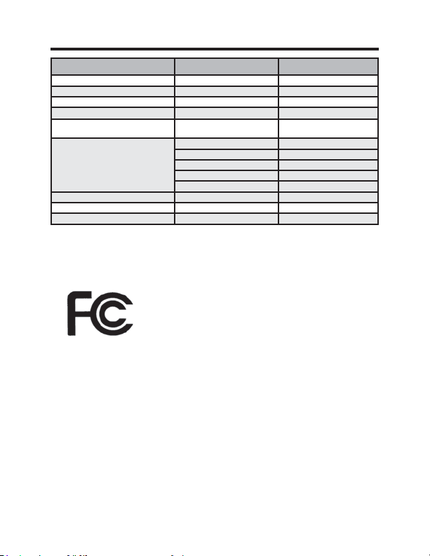
31 49-5000637 Rev. 0
Especificaciones Técnicas
Termostato Tarjeta de Control Inalámbrico
Dimensiones de la Carcasa (Imperial) 4.015 x 5.5118” x 0.925” 3.875” x 2.125” x 0.75”
Dimensiones de la Carcasa (Métrica) 102mm x 140mm x 23.5mm 98mm x 54mm x 19mm
Dimensiones de la Pantalla (Imperial) 3.625” x 2.125” N/A
Dimensiones de la Pantalla (Métrica) 92mm x 54mm N/A
tensión de funcionamiento 3V DC - 2 “AA” Cell Batteries
OR(Optional) 24V AC/DC
24V AC/DC
Salidas del Control Ventilador Alto (GH)
Ventilador Bajo (GL)
Compresor (Y)
Bomba de Calor (OB)
Calor Eléctrico (W2)
Frecuencia Inalámbrica 900MHz 900MHz
Precisión de la Temperatura ±1°F N/A
FCC ID XEYWX XEYV8ACCC
DECLARACIÓN DE LA FCC
Este dispositivo cumple con la Parte 15 de
las normativas de la FCC. Su funcionamiento
está sujeto a las dos condiciones siguientes: (1) Este dispositivo
no deberá causar interferencias nocivas y (2) este dispositivo
deberá aceptar cualquier interferencia recibida, incluyendo inter-
ferencias que puedan generar un funcionamiento no deseado.
De acuerdo con la parte 15.21 de las normativas de la FCC,
FXDOTXLHUFDPELRRPRGL¿FDFLyQVREUHHVWHHTXLSDPLHQWRQR
aprobados expresamente por GE Appliances podrá anular la
autoridad del usuario para utilizar el equipamiento.
32 49-5000637 Rev. 0
GARANTÍA LIMITADA DEL TERMOSTATO
Por el Período de: GE Appliances Brindará:
Un Año
Un reemplazo completo del termostato si falla debido
Desde la fecha de a un defecto en los materiales o la fabricación.
la compra original
Qué No Cubrirá GE Appliances:
Ŷ9LDMHVGHOVHUYLFLRWpFQLFRKDVWDVXXELFDFLyQ
Ŷ,QVWDODFLyQLQDGHFXDGD6LWLHQHXQSUREOHPDFRQODLQVWDODFLyQFRPXQtTXHVHFRQ
su instalador. Usted es responsable de brindar conexiones eléctricas adecuadas
sobre el producto.
Ŷ&XDOTXLHUIDOODGHOSURGXFWRFRPRUHVXOWDGRGHPRGLILFDFLRQHVHQHOPLVPRRGHELGR
a un uso inadecuado, incluyendo la falta de mantenimiento razonable o necesario.
Ŷ(QXELFDFLRQHVFRPHUFLDOHVWUDEDMRQHFHVDULRSDUDPRYHUODXQLGDGOXHJRGHTXH
haya sido inicialmente instalada, a una ubicación donde se encuentre accesible
para el servicio técnico por parte de un técnico individual; o, si las instrucciones
de este manual fueron ignoradas.
Ŷ5HHPSOD]RGHIXVLEOHVGHODFDVDRUHLQLFLRGHGLV\XQWRUHV
Ŷ'DxRVRFDVLRQDGRVVREUHHOSURGXFWRSRUQLYHOGHVXPLQLVWURGHYROWDMH
inadecuado, accidentes, incendios, inundaciones o catástrofes naturales.
Ŷ'DxRVLQFLGHQWDOHVRFRQVHFXHQWHVFDXVDGRVSRUSRVLEOHVGHIHFWRVVREUHHVWH
termostato.
Abroche su recibo aquí. Para validar la garantía deberá contar con la prueba
de la fecha original de compra.
Esta garantía limitada se extiende al comprador original y a cualquier dueño
subsiguiente de productos comprados para uso dentro de EE.UU. y Canadá. En
Alaska, la garantía limitada excluye el costo de envío o llamadas del servicio a
su hogar. Algunos estados o provincias no permiten la exclusión o limitación de
daños fortuitos o consecuentes. Esta garantía limitada le da derechos legales
específicos, y es posible que tenga otros derechos que varían entre un estado
y otro, o entre una provincia y otra. Para conocer cuáles son sus derechos
legales, consulte a la oficina de asuntos del consumidor local, estatal o provincial
o al Fiscal de su estado.
Garante: GE Appliances, Louisville, KY 40225
EXCLUSIÓN DE GARANTÍAS IMPLÍCITAS—Su única y exclusiva alternativa es el
cambio del producto, como se indica en la Garantía Limitada. Las garantías implícitas,
incluyendo garantías implícitas de comerciabilidad o conveniencia sobre un
propósito particular, se limitan a un año o al período más corto permitido por la ley.
Para solicitar ayuda en relación a la solución de problemas del termostato, co-
muníquese al 1-844-GE4-PTAC option 1 (o al 844-434-7822)