Installation Instructions
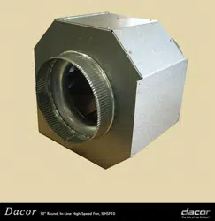
In-Line Blower
Models: ILHSF8, ILHSF10
Part No. 103719 Rev. F
Suitable for use in a household cooking area.
Suitable for use with solid state controls.
To complete this blower, the hood assembly must be purchased separately.
See the hood installation instructions to determine suitability.

Installation Instructions .................................................... 5
Installation Preparation .................................................... 5
Installation ........................................................................ 5
Verifying Proper Operation ............................................... 6
Technical Data ................................................................... 7
Blower Ratings ................................................................. 7
Wiring Diagram ................................................................ 7
Notes................................................................................... 8
Table of Contents
Before You Begin...
Important Safety Instructions .......................................... 1
Important Information About Safety Instructions .............. 1
Safety Symbols and Labels ............................................. 1
General Safety Precautions ............................................. 2
Product Specifications ..................................................... 3
Product Dimensions ......................................................... 3
Electrical Specifications ................................................... 4
Installation Planning ......................................................... 4
All specifications subject to change without notice. Dacor assumes no liability for changes to specifications.
Important:
• Installer: In the interest of safety and to minimize problems, read these installation instructions completely and care-
fully before you begin the installation process. Leave these installation instructions with the customer.
• Customer: Keep these installation instructions for future reference and for the local electrical inspector’s use.
© 2008 Dacor, all rights reserved.
If You Need Help...
If you have questions or problems with installation, contact
your Dacor
®
dealer or the Dacor Customer Service Team. For
repairs to Dacor appliances under warranty call the Dacor
Distinctive Service line. Whenever you call, have the model
and serial number of the blower ready. The model and serial
number are printed on the appliance data label on the unit.
Dacor Customer Service Team
Phone: (800) 793-0093 ex. 2813 (U.S.A. and Canada)
Monday — Friday 6:00
a.m. to 5:00 p.m. Pacific Time
Web site: www.dacor.com
Dacor Distinctive Service (for repairs under warranty only)
Phone: (800) 793-0093 ex. 2822 (U.S.A. and Canada)
Monday — Friday 6:00
a.m. to 5:00 p.m. Pacific Time
Customer Service Information
Model Identification
ILHSF8 = 8-inch in-line blower
ILHSF10 = 10-inch in-line blower
1
Important Information About
Safety Instructions
• The Important Safety Instructions and warnings in
these instructions are not meant to cover all possible
problems and conditions that can occur. Use common
sense and caution when installing, maintaining or oper-
ating this or any other appliance.
• Always contact the Dacor Customer Service Team
about problems and conditions that you don’t under-
stand. See Customer Service Information above.
Important Safety Instructions
Safety Symbols and Labels
DANGER
Immediate hazards that WILL result in severe personal
injury or death.
WARNING
Hazards or unsafe practices that COULD result in severe
personal injury or death.
CAUTION
Hazards or unsafe practices that COULD result in minor
personal injury or property damage.
DANGER
IMPORTANT: Do not store or use combustible,
flammable or explosive vapors and liquids (such as
gasoline) inside or in the vicinity of this or any other
appliance. Also keep items that could explode, such
as aerosol cans, away from the range or cooktop. Do
not store flammable or explosive materials in adjacent
cabinets or areas.
WARNING
WARNING - TO REDUCE THE RISK OF FIRE,
ELECTRIC SHOCK, OR INJURY TO PERSONS,
OBSERVE THE FOLLOWING:
a) Use this unit only in the manner intended by the man-
ufacturer. If you have questions, contact the manufac-
turer.
b) Before servicing or cleaning unit, switch power off
at service panel and lock the service disconnecting
means to prevent power from being switched on acci-
dentally. When the service disconnecting means can-
not be locked, securely fasten a prominent warning
device, such as a tag, to the service panel.
WARNING
TO REDUCE THE RISK OF FIRE, USE ONLY METAL
DUCTWORK.
WARNING
WARNING - TO REDUCE THE RISK OF FIRE,
ELECTRIC SHOCK, OR INJURY TO PERSONS,
OBSERVE THE FOLLOWING:
a) Installation work and electrical wiring must be done by
qualified person(s) in accordance with all applicable
codes and standards, including fire-rated construc-
tion.
b) Sufficient air is needed for proper combustion and
exhausting of gases through the flue (chimney) of fuel
burning equipment to prevent back drafting. Follow
the heating equipment manufacturer’s guideline and
safety standards such as those published by the
National Fire Protection Association (NFPA), and the
American Society for Heating, Refrigeration and Air
Conditioning Engineers (ASHRAE), and the local
code authorities.
c) When cutting or drilling into wall or ceiling, do not
damage electrical wiring and other hidden utilities.
d) Ducted fans must always be vented to the outdoors.
WARNING
For general ventilating use only. Do not use to exhaust
hazardous or explosive materials or vapors.
READ AND SAVE THESE INSTRUCTIONS
2
Important Safety Instructions
• Do not install or operate this unit if it has been dam-
aged, dropped, has damaged electrical wiring or is
not working properly. If the product is damaged when
received, immediately contact the dealer or builder.
• Use this blower only for its intended purpose as out-
lined in these instructions. This blower is not intended
for commercial use.
• All planning, installation work and electrical wiring
must be performed in accordance with all governing
codes and ordinances, including fire-rated construc-
tion. Contact your local building department for fur-
ther information.
• Install or locate this appliance only in accordance
with these installation instructions and the Dacor
hood or downdraft vent installation instructions.
Improper installation, adjustment, alteration, service
or maintenance can cause serious personal injury or
property damage.
• Before installing or servicing the in-line blower, make
sure that power to the wiring is turned off at the cir-
cuit breaker or fuse box. Make sure that the service
panel is locked or tagged to prevent power from
being switched on accidently.
• To reduce the risk of electric shock or fire, the total
combined current draw of the in-line blower and the
hood or downdraft vent must not exceed the maxi-
mum rated input current of the hood or downdraft
vent.
WARNING
General Safety Precautions
To reduce the risk of fire, electric shock, serious injury or death when using this blower, follow basic safety precautions,
including the following:
• The installer must show the customer the location of
the fuse or circuit breaker panel so that the customer
knows where and how to turn the power off.
• Never allow the filters or vent openings on the hood
or downdraft vent to become blocked or clogged. Do
not allow foreign objects, such as cigarettes or nap-
kins, to be sucked into the vent holes.
• Clean the filters and all grease-laden surfaces around
the hood or downdraft vent often to prevent grease
fires and maintain performance.
• Use only duct work constructed of materials deemed
acceptable by state, municipal and local codes.
• Tape all duct joints securely to prevent combustion
by-products, smoke or odors from entering the home.
Doing so will also improve system efficiency.
• Do not route electrical wiring near hot surfaces.
• Do not ground the appliance with the neutral (white)
house supply wire. A separate ground wire must be
utilized.
• To prevent a damaged or non-functional system,
complete electrical connections properly. Follow the
wiring diagrams carefully in the hood or in-line blower
installation instructions to ensure a proper installation.
After installation or service, make sure that all blower
wires are tightly connected to their respective termi-
nals.
WARNING
3
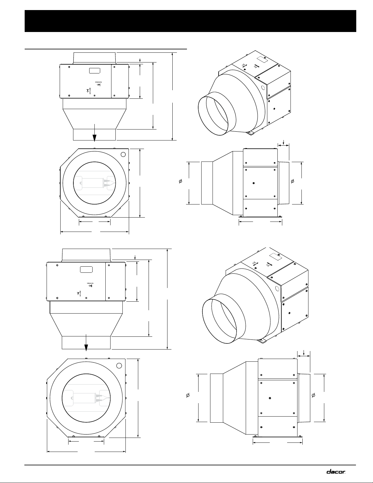
Product Dimensions
Product Specifications
3/16” (0.5 cm)
(16.5 cm)
6 ½"
(33.6 cm)
13 ¼"
(33.0 cm)
Air Flow
13”
(20.3 cm)
(20.8 cm)
8” REF
8 3/16”
(5.7 cm)
2 1/4”
(20.3 cm)
8” REF
(33.0 cm)
13”
(15.2 cm)
6”
(41.9 cm)
16 ½"
3/16” (0.5 cm)
15 1/4”
(38.7 cm)
19”
(48.3 cm)
16”
(40.6 cm)
8 1/4”
(21.0 cm)
15 3/4”
(40.0 cm)
10 3/4”
(27.3 cm)
2 1/4”
(5.7 cm)
10” REF
(25.4 cm)
10” REF
(25.4 cm)
9 1/8”
(23.2 cm)
Air Flow
All tolerances: ±1/16”, (±1.6 mm) unless otherwise stated
ILHSF8
ILHSF10
4
Installation Planning
WARNING
To avoid the risk of fire due to the unit overheating:
• DO NOT install this blower with a hood or raised vent
that has an internal blower.
• DO NOT install more than one blower to increase
the length of the duct run. Even small differences
between blower air flow rates can greatly reduce the
air drawn by the hood or raised vent.
• For optimal performance, consult a qualified HVAC
specialist before installation.
• Consult the installation instructions for the raised vent
or hood for complete layout and duct system plan-
ning instructions. Observe all location and duct system
design instructions.
• To minimize noise, install the blower at the mid-point
between the raised vent or hood and the duct system
exhaust. Minimum recommended distance from the
vent/hood or exhaust is 5 feet.
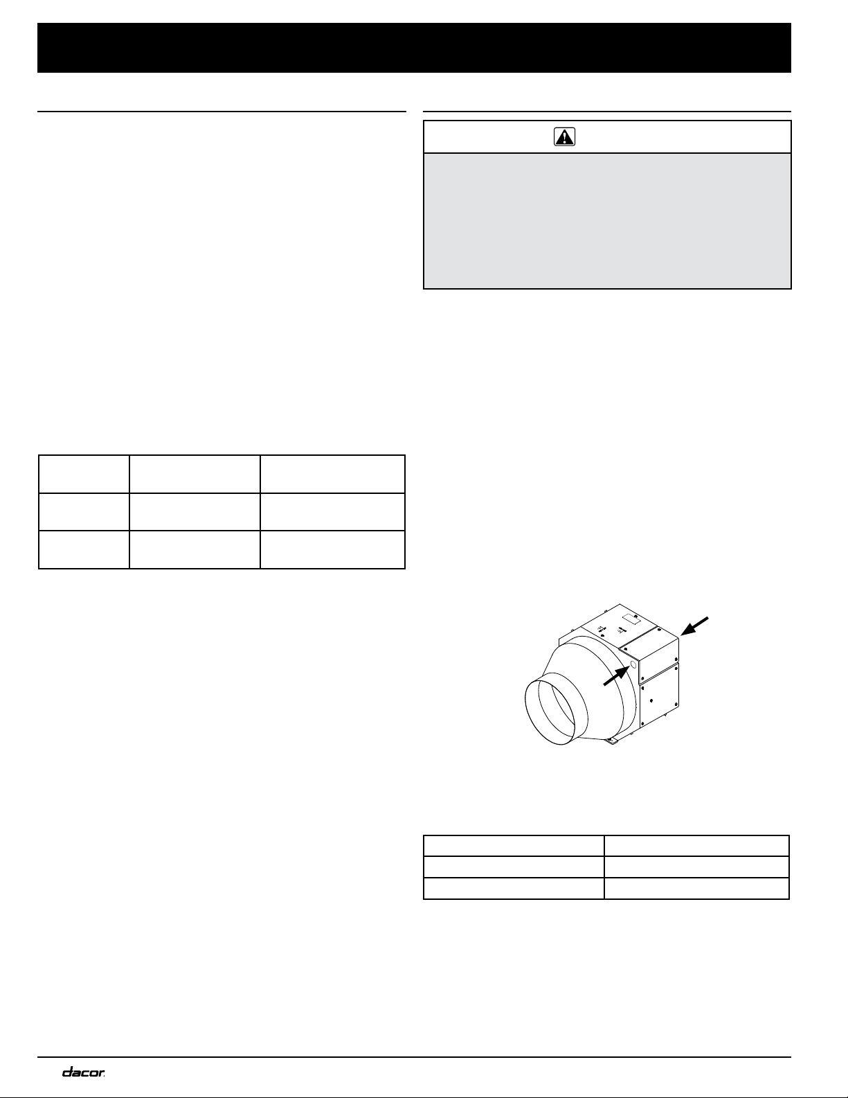
General System Design Notes
• Wire the remote blower to turn on when the raised
vent or hood is turned on by running a piece of conduit
parallel to the duct work and connecting it to the raised
vent or hood on one end and the in-line blower on the
other. There are two 1/2” electrical access hole knock
outs in the sides of the blower’s electrical access panel.
Electrical Access Knock-outs
• Select a location that can properly support or can be
reinforced to support the weight of the blower.
Model Number Weight
ILHSF8 22 lbs. (10 kg.)
ILHSF10 31 lbs. (14 kg.)
• Install the blower so that it can be removed if service is
required.
• Plan the installation so that all minimum dimensions
are met or exceeded. All contact surfaces between the
blower and any mounting surfaces must be solid and at
right angles.
• The mounting surface must be thick enough to accom-
modate screws 2” in length.
Electrical Specifications
Electrical Supply Requirements
• The power for this blower is supplied via 1/2” 3-wire
conduit (not included) by an approved Dacor hood or
raised vent. The conduit is installed between the hood
or raised vent and the blower and shall be terminated
on each end by a 1/2” UL certified strain relief. The
power is turned on and off by the power switch on the
approved ventilation device.
• The correct voltage, frequency and amperage must be
supplied to the hood or raised vent and the blower from
a grounded, single phase circuit that is protected by a
properly sized circuit breaker or time-delay fuse. The
circuit must have the capacity to supply the combined
power requirements for the hood or raised vent and the
in-line blower. See the installation instructions for the
hood or raised vent to determine total power require-
ments in combination with the blower electrical specifi-
cations.
Blower Electrical Specifications
Model
Number*
Power
Requirements**
Nominal
Blower Rating***
ILHSF8
120 Vac, 60 Hz,
3.5 Amp.
600 CFM
ILHSF10
120 Vac, 60 Hz,
4.5 Amp.
1100 CFM
* All models are thermally protected.
** In addition to the hood or raised vent
***
At 0 inches static pressure. See Technical Data for
actual rating and other performance data.
The above specifications are for reference only, See the
data label on the blower for exact specifications. If the
above specifications vary from the label on the blower, use
the data on the blower label.
• It is the owner’s responsibility to ensure that the electri-
cal connection of this blower is performed by a qualified
electrician. The electrical installation, including mini-
mum supply wire size and grounding, must be in accor-
dance with the National Electric code ANSI/NFPA* (or
latest revision) and local codes and ordinances.
* A copy of the specification may be obtained from:
National Fire Protection Association
1 Batterymarch Park
Quincy, Massachusetts 02269-9101
• If the electrical service provided does not meet all prod-
uct specifications, or does not conform to the NEC or
local standards, do not proceed with the installation.
Call a licensed electrician to correct the electrical ser-
vice before proceeding.
Product Specifications
GRN
L1
BLU
BLK
GND
N1
5
Installation Preparation
Verify Package Contents
• Blower assembly
Parts Required
• Four (4) #10 x 2”, round head screws (suitable for the
material the blower will be mounted to).
• 1/2” 3 wire conduit with a 1/2” UL certified strain relief
on each end (length is determined by in-line blower
location). See the Electrical Supply Requirements
section for complete specifications.
• Also consult the hood or raised vent installation instruc-
tions for additional parts required.
Installation
WARNING
• If the electrical service provided does not meet the
power requirements for the hood/raised vent and the
blower combined, do not continue with the installation.
Contact a licensed electrician to correct the situation
before continuing.
• Failure to connect the wiring as specified may result
in an electric shock hazard and/or improper blower
operation.
• To avoid the risk of fire or electric shock, turn off
power at the circuit breaker panel or fuse box before
connecting the blower to the power source.
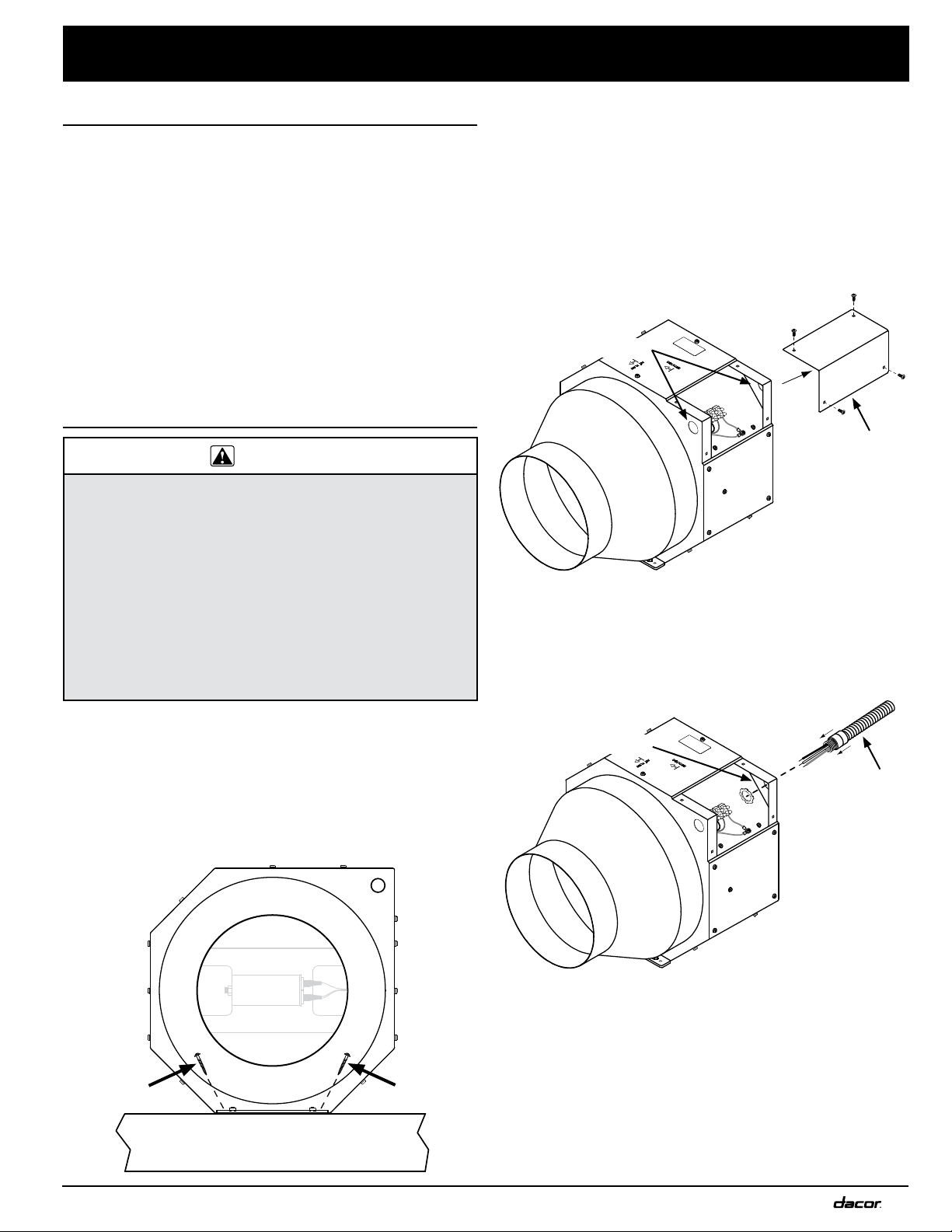
Blower Mounting
1. Hold the blower steady in the mounting location. Make
sure that the “AIR FLOW” arrow on the chassis points
toward the exhaust duct’s path to the outdoors.
2. Attach it using four (4) #10 x 2”, round head screws.
Insert the screws at an angle as shown.
Electrical Installation
1. Run the conduit line used to supply power from the
installed raised vent or hood to the in-line blower paral-
lel to the duct work.
2. Make sure that power to the raised vent or hood is
disconnected or turned off at the circuit breaker or fuse
box.
3. Remove the electrical access cover from the in-line
blower to expose the power terminals.
4. Remove one of the conduit knock-outs from one side of
the blower.
5. With the UL certified strain relief attached to the end of
the conduit, feed the end of the conduit into the hole
and attach it to the side of the blower.
Installation Instructions
GRN
L1
BLU
BLK
GND
N1
Electrical access
cover
Knock-outs
GRN
L1
BLU
BLK
GND
N1
Conduit
Hole
Mounting
surface
Blower
6
GRN
L1
BLU
BLK
GND
N1
13. Install the duct work according to the installation
instructions for the hood or raised vent. Support the
duct weight as necessary to ensure properly sealed
joints.
Verifying Proper Operation
WARNING
Read the raised vent or hood use and care manual
completely before operation.
Test the blower operation according to the Verify Proper
Operation section of the hood or raised vent installation
instructions.
1. If the blower does not work, check all input and output
power connections at the hood or raised vent.
2. Check the blower power terminal connections.
If the installation still does not work, contact Dacor
Distinctive Service at (800) 793-0093 ex. 2822. Do not
attempt to repair the blower, hood or raised vent yourself.
Be sure to have all model and serial numbers from the
product data labels available when you call.
Dacor is not responsible for the cost of correcting problems
caused by a faulty installation.
Electrical Installation (continued)
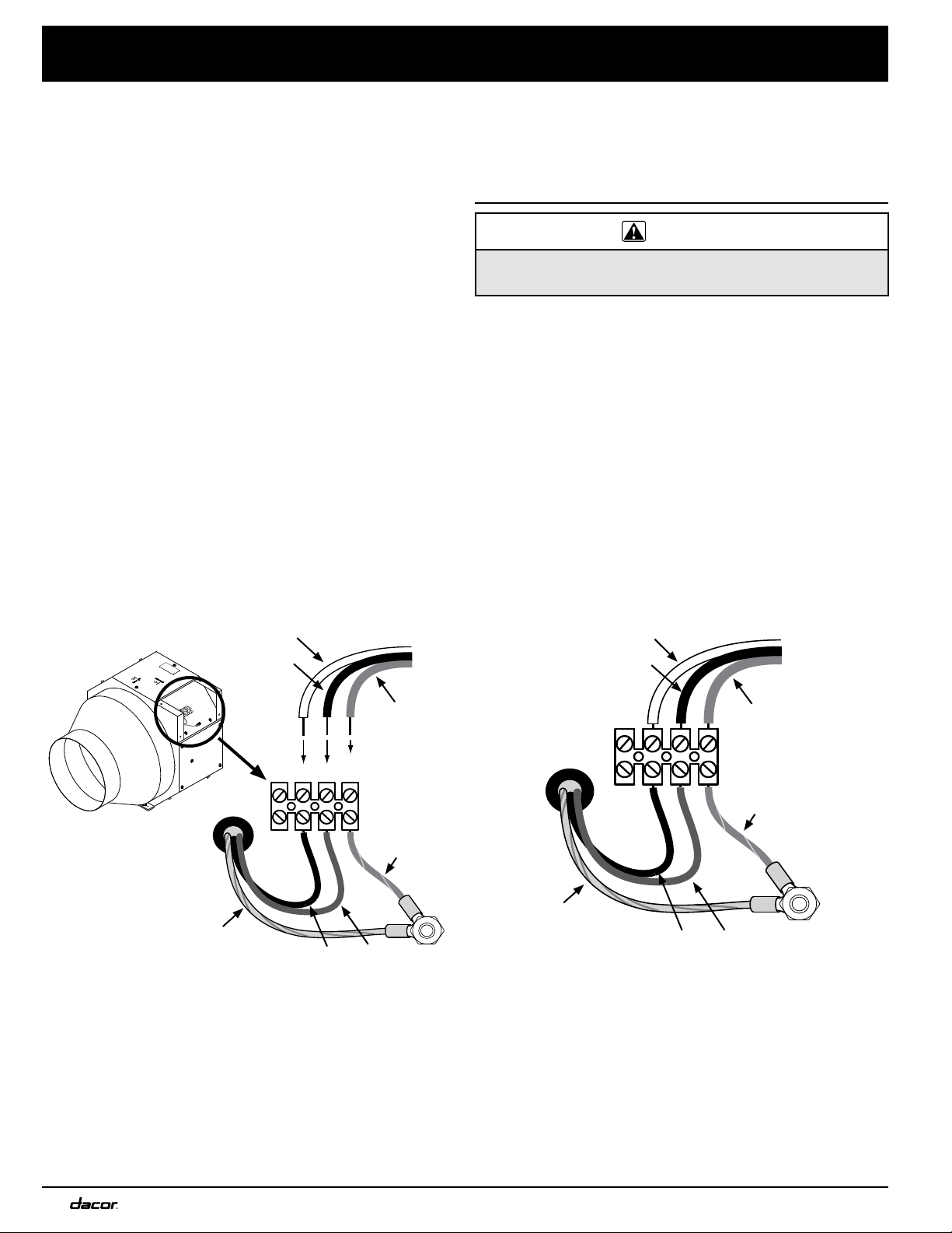
6. Strip the three conduit wires.
7. Connect the white (neutral) wire from the conduit to
the N1 blower power terminal (see Figure 1). Tighten
the terminal screw firmly into place. IMPORTANT: The
neutral terminal on the blower has the BLACK wire
from the blower motor connected to it.
8. Connect the black (L1) wire from the conduit to the
L1 blower power terminal (see Figure 1). Tighten the
terminal screw firmly into place. IMPORTANT: The L1
(hot) terminal on the blower has the BLUE wire from
the blower motor connected to it.
9. Connect the green (GND) wire from the conduit to the
GND blower power terminal (see Figure 1). Tighten the
terminal screw firmly into place.
10. Check the wires from the blower motor to make sure
that they are firmly attached to the terminal according
to Figure 2 below. Reconnect any wires that are loose.
Make sure all terminal screws are tight. Also make sure
the nut on the ground lug is tight.
11. Replace the blower electrical access panel.
12. Secure the other end of the conduit to the hood or
raised vent and connect the wires according to the
hood or raised vent installation instructions.
Installation Instructions
Ground
lug
Figure 1:
Conduit Wire Connection
GRN
L1
BLU
BLK
GND
N1
L1N1
Not
Used
Wires from
blower motor
Wires from
conduit
Black
Black
Yellow
Blue
Green
White
Green
Figure 2:
Final Blower Wiring Diagram
Wires from
blower motor
Wires from
conduit
Black
Black
Yellow
Blue
Green
White
Green
7
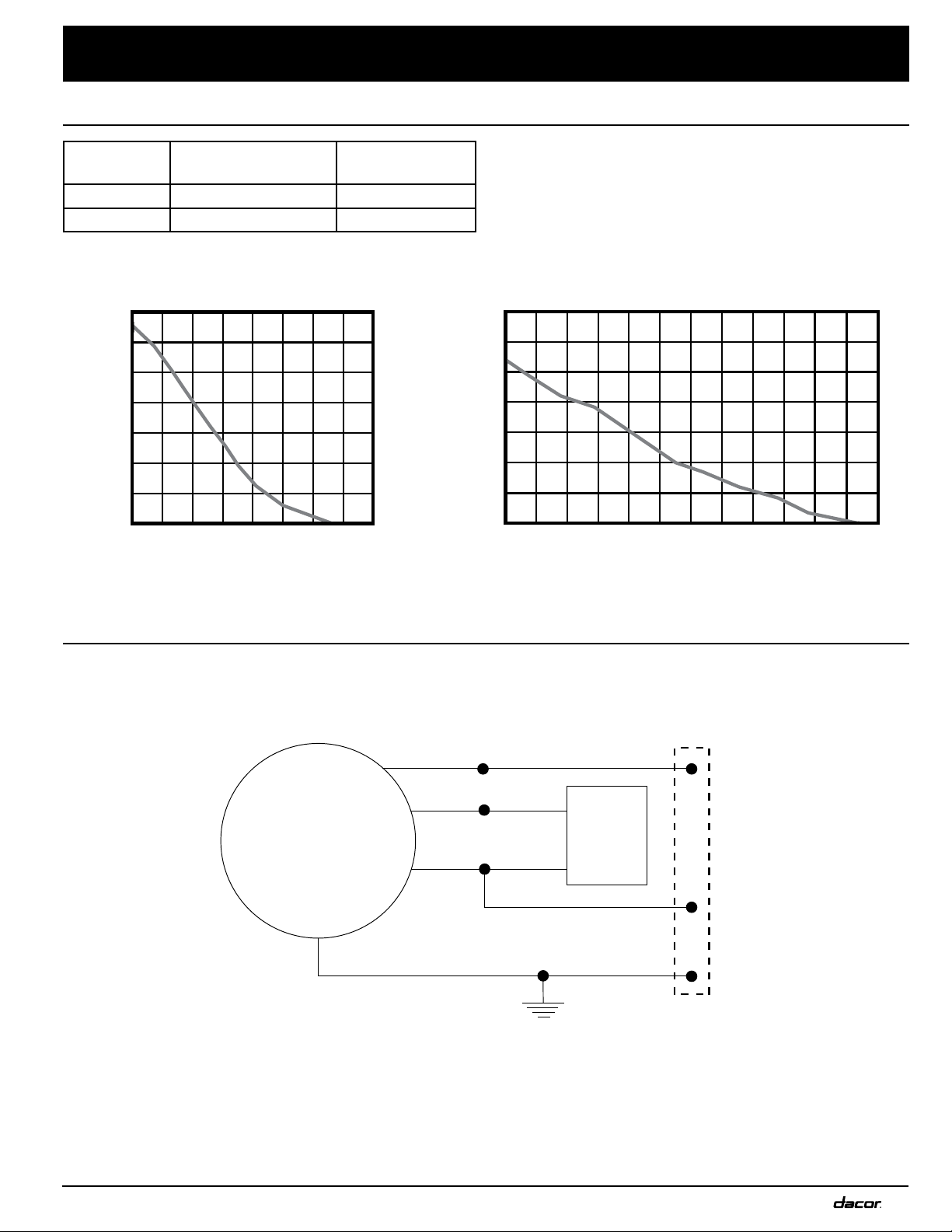
Technical Data
Blower Ratings
Wiring Diagram
Model
Number
Nominal
Rating*
Actual
Rating*
ILHSF8 600 CFM 650.7 CFM
ILHSF10 1100 CFM 1115.9 CFM
* At zero inches static pressure
Airflow CFM (Cubic feet/minute)
Static pressure - inches of water
0
0.5
1.0
1.5
2.0
2.5
3.0
3.5
200 400 600 800 1000 1200
ILHSF10 Blower Performance
Airflow CFM (Cubic feet/minute)
Static pressure - inches of water
0
0.5
1.0
1.5
2.0
2.5
3.0
3.5
200400 600800
ILHSF8 Blower Performance
Permanent
PSC “Type E” Motor
split capacitor
motor
Yellow/Green
Blue Blue
Terminal
block
Green/Yellow
GND
N1
L1
BrownBrown
BlueBlack
Black
Motor
run
capacitor

8
Notes


Dacor●14425ClarkAvenue,CityofIndustry,CA91745●Phone:(800)793-0093●Fax:(626)403-3130●www.dacor.com