Loading ...
Loading ...
Loading ...
© 2021 United States Stove Company
13
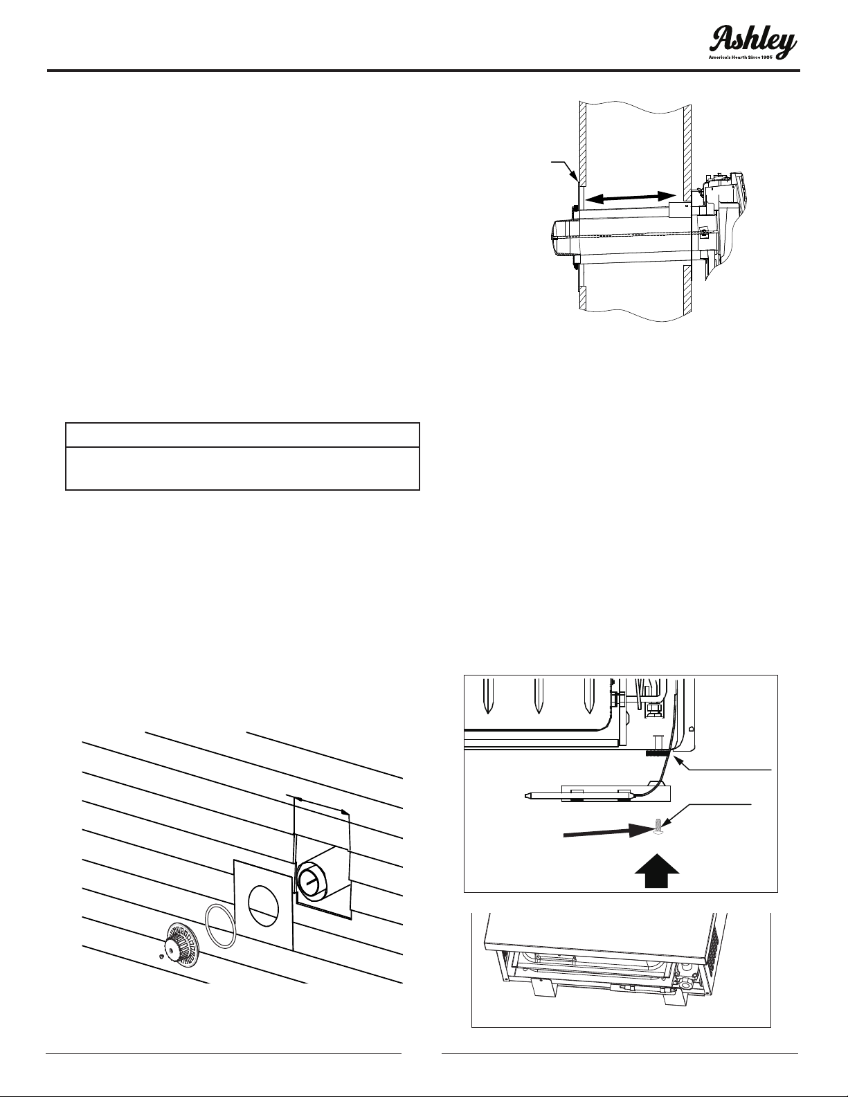
5. Slide the vent pipe (B) and vent-air intake pipe
(C) through the hole in the wall, and connect
them to the appliance ue outlet and air
intake,respectively.
6. The outdoor mounting plate (F) and the silicon-
rubber ring (G) should be installed between
the vent cap (A) and the exterior wall. Note: For
additional security the outdoor mounting plate
(F) can be attached to the outside of the wall
using the appropriate hardware for mounting
to the surface of the building. The outdoor
mounting plate (F) must be positioned ush
to the wall and sealed with a non-hardening
mastic (silicone caulk). Position the outdoor
mounting plate (F) so that the vent-air intake
pipe (C) has a slight downward slope of 1/4” per
foot of venting to the outside.
ATTENTION:
THE DOWNWARD SLOPE IS NECESSARY TO
PREVENT THE ENTRY OF RAINWATER.
7. Before attaching the vent cap (A) to the exterior
wall, run a bead of non-hardening mastic
(silicone caulk) around its outside edge, so
as to make a seal between it and the outdoor
mounting plate (F) (see gure 15).
8. Slide the vent cap (A) into position and secure
into place using the provided nut (E). Tighten
nut (E) down until the vent cap (A) leans against
the outdoor mounting plate (F) (see gures 14
and 15).
11-1/4" (286mm) x 11-1/4" (286mm)
square hole
REQUIRED:
Downward slope
of 1/4” per foot
of venting to the
outside
Flush with
Mastic
Figure 14
11-1/4" (286mm) x 11-1/4" (286mm)
square hole
REQUIRED:
Downward slope
of 1/4” per foot
of venting to the
outside
Flush with
Mastic
Figure 15
INSTALLING THE THERMOSTAT SENSOR
In order to protect the thermostat sensor from
any damage during shipping, or while handling
it before it is denitely installed, the thermostat
sensor has not been attached to its nal location in
the appliance. So, once the heater is installed, the
thermostat sensor must be placed and secured in
position. To do so, follow these steps:
1. Reach in through the bottom of the unit and
cut the cable tie holding the thermostat sensor
to the unit.
2. Place the thermostat sensor under the right
bottom of the bracket and attach it with
the provided medium screw (i) that xes the
appliance to the bracket as shown in gures 16
and 17.
Figure 16
Figure 17
SCREW
BRACKET
i
x 1
Figure 16
Figure 17
SCREW
BRACKET
i
x 1
INSTALLATION
Loading ...
Loading ...
Loading ...