Loading ...
Loading ...
Loading ...
14
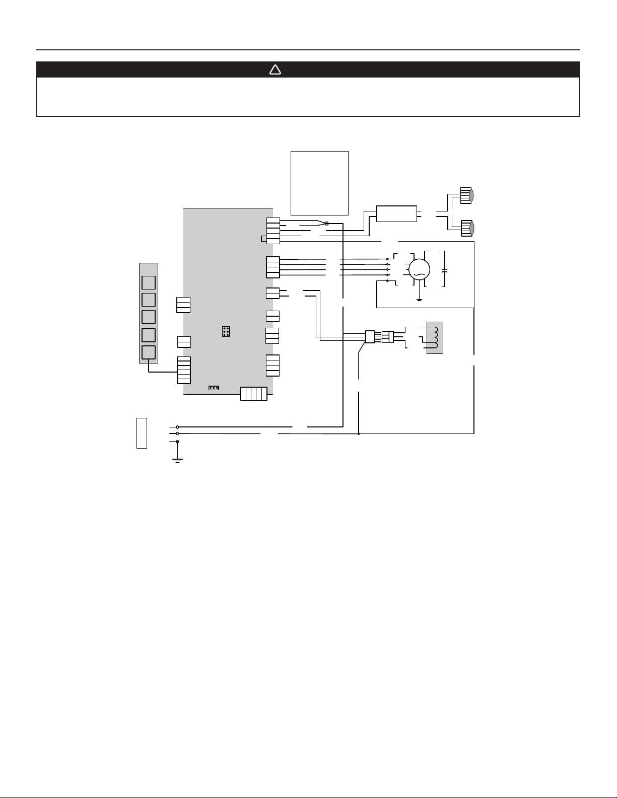
21. WIRING DIAGRAM
Line
Neutral
Ground
120 V AC
BLK BLACK
BLU BLUE
BRN BROWN
GRN GREEN
GRY GREY
ORG ORANGE
RED RED
WHT WHITE
YEL YELLOW
COLOR CODE
16 Pins
LED driver
Input
Output
LED
LED
User interface
T1 (10 VAC)
J13
FAN MOTOR
1
3
2
5
4
J12
User Interface
J1
10VAC
J8
Aux. Input
3
2
1
RP1
J3
Programmer
header
Triac Ext
J7
J11
12VDC
+
-
J4
Motor
Speed
J2
120V-Motor-Lamp
1
J10
J9 Serial Com
5
4
32
1
J5
Output
J6
External
Triac
2
3
4
5
1
2
3
4
1
2
1
2
1
2
3
4
1
2
3
1
2
YEL
BLK
BLK
WHT
WHT
WHT
RED
RED
RED
BLU
WHT
ORG
BLK
WHT
BLK
WHT
RED
RED
WHT
BLK
WHT
RED
GRY
BRN
BLU
WHT
ORG
BLK
HE0065A
WARNING
VQ0010
!
Risk of electric shock. Electrical wiring must be done by qualified personnel in accordance with all applicable
codes and standards. Before connecting wires, switch power off at service panel and lock service disconnecting
means to prevent power from being switched on accidentally.
Loading ...
Loading ...
Loading ...