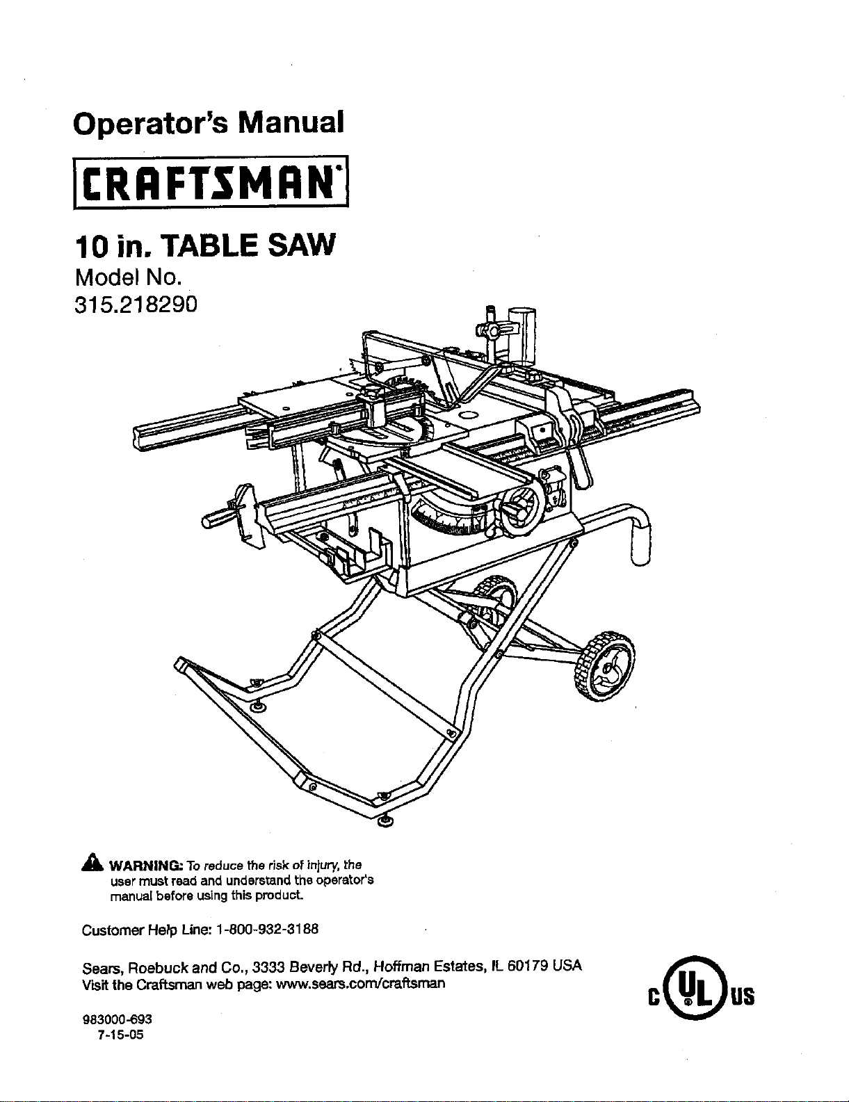
Operator's Manual
10 in. TABLE SAW
Model No,
315.218290
_k WARNING: To reducethe risk of injury,the
user mustread and understandthe operator's
manual beforeusingthis product.
Customer Help Line: 1-800-932-3188
Seam, Roebuck and Co., 3333 BeverPy Rd., Hoffman Estates, IL 60179 USA
Visit the Craftsman web page: www.seam.com!cmffsman
983000-693
7-15-05

Warranty ............................................................................................................................................................................ 2
Introduction....................................................................................................................................................................... 2
GenareJSafety Rules......................................................... ............................................................................................ S--4
SpecificSat°styRules.................................... ................................................................................................................. 4-5
Symbols......................................................................................................................................................................... 6-7
EIac_ca( ............................................................................................................................................................................ 6
Glossaryof Tsn'ns.............................................................................................................................................................. g
Features..................................................................................................................................................................... 10-13
ToolsNeeded ................................................................................................................................................................. 13
Loose Parts............................................................................................................................................................... 14-15
Assembly................................................................................................................................................................... 16-22
Operation................................................................................................................................................................... 22-39
Adjustments.............................................................................................................................................................. 40-44"
Maintenance................................................................................................................................................................... 45
Accessories.................................................................................................................................................................... 46
Troubleshooting......................................................................................................................................................... 46-47
ExplodedView........................................................................................................................................................... 4-8-57
Parts Ordering/Service...................................................................................................................................... BackPage
ONE YEAR FULL WARRANTY ON CRAFTSMAN TOOL
Ifthis Craftsmantool fails due to a defectin materialor workmanshipwithinone yearfrom the date of purchase,Call
1-B00-4-MY-I-IOME O to arrangefor freerepalr.If thlstool is used for commercial or rentalpurposes, thiswarrantywill
apply for onlyninetydays from the date ofpurohass.This warrantyappilesonly whilethis productisin theUnited States.
This warranty givesyou specificlegal rights,and you may eJso haysotherrightswhichvaryfrom stats tostate.
Seam, Roebuck and Co., Dept. 8t7WA, Hoffman Estates, IL 60179
This tool hasmany featuresfor makingits use more pleasantand enjoyable.Safety,performance,and dependability
have been giventop priorityin thedesign of this productn'_.kingit easy to maintain and operate.
2

_k WARNING." Reed and understand all insb'ue-
tions, Failureto re[low all instruckions{istadbelow,
may resuttin electricshock,fire andlor serious
personal injury.
READ ALL iNSTRUCTIONS
• KNOW YOUR POWER TOOL. Read the operator's
manualcarefully.Learn the saw's applicationsand
Iimftationsaswet[es the specificpotenti_ hazards
related to thistool.
• GUARD AGAINST ELECTRICAL SHOCK BY PRE-
VENTING BODY CONTACT WITH GROUNDED
SURFACES-For examp}e,pipes, radiators,ranges,
refrigeratorenclesures.
• KEEP GUARDS IN PLACE and ingood workingorder.
• REMOVE ADJUSTING KEYS AND WRENCHES.
Formhabit of checkingto see that keysand adjusting
wrenchesare removedfrom toolbefore turningiton.
• KEEP WORK AREA CLEAN. Clutteredareas and
benchesinviteaceidents. DO NOT leavetoolsor
pieces otwood onthe sawwhile itis inoperation.
• DO NOT USE IN DANGEROUS ENVIRONMENTS.
Do not usepower toolsin damp or wet locationsor
exposeto rain.Keep the work areaweI_s_.
• KEEP CHILDREN AND VISITORS AWAY.Allvisitors
shouldwear safetyg_aesasand be kepta safe
distancefromwork ares. Do not let visitorsosntact
toolor extensioncordwhile operating.
• MAKE WORKSHOP CHILDPROOF with padlocksand
master switches,orby removings_,_'terkeys.
• DON'T FORCE TOOL. Itwilldo the job better and
saferat thefeed rote for which itwas designed.
• USE RIGHT TOOL, Don't rome the toolor attachment
to do a jobitwas not designedfor. Don't use itfor a
purposenot intended.
• USE THE PROPER EXTENSION CORD. Make sure
your extensioncord isin good condition.Useon[ya
cordheavyenoughtocarrythecurrentyourprodu_
willdraw.An undersizedcord will causea drop inline
voltageresultingin_oesofpower and overheating.A
wire gauges'_e (A.W.G.)ofat least14 isrecommended
for an extensioncord25 feet or lessin length. Ifin
doubt,usethenext heavier gauge.The smallerthe
gauge number, the heavierthe cord.
• DRESS PROPERLY.Do not wear looseclothing,
gloves,neckties, orjewelry.They can get caught
and draw you intomoving parts.Rubber glovesand
nonskidfoo[wser are recommendedwhen working
outdoors.Alse wear protecl:'Nehairosver;ng to contain
long hak.
• ALWAYSWEAR SAFETYG_ESWITI-I SIDE
SHIELDS. Everyday eyeglasseshave onlyimpact-
resistantlenses, they are NOT safety gtaseas.
• SECURE WORK, Use clamps oravise to hold work
when pc_ctical._fs safert_n using your han_ an
_ees both handsto operatetool.
• DON'T OVERREACH. Keep properfootingand
ba_nco at sit times.
• MAINTAIN TOOLS WITH CARE. Kesptoolssherp
and clean for better and saferperformanca.FoJiow
instructionsfor lubricatingand changingaccessories.
• DISCONNECT TOOLS. When notin use, before
servicing,or when changingaLl_chmants,blades, bits,
cutters,etc., antoolsshouldbe disconnected.
• AVOID ACCIDENTAL STARTING. Be sureswitchis off
when plugging in anytooL
• USE RECOMMENDED ACCESSORIES. Consultthe
operator'smanualfor recommendedaccessories.The
useof improperaccessoriesmay riskinjury.
• NEVER STAND ON TOOL, Seriousinjurycouldoccur
if thetoolistipped or ifthe cuttingtoo[ isunintention-
_lly con_.cted.
• CHECK DAMAGED PARTS. Beforefurther useof
the toot,a guard or otherpart thatis damagedshould
be carefuttychecked to determinethat itwill operate
propedyand performits intendedfunction. Check for
al{gnn_ntof movingparts, b(n_ingot movingparts,
breakageof parts, mountingand anyother conditioP.s
that may affect itsoparatien.A guardor o_er part _at
is damagedmust be properlyrepairedor replaced by
_.nau'thofized service centerto avoidrisk of personal
ir_u_
• USE THE RIGHT DIRECTION OF FEED. Feed work
intoa blade or cutleragainstthe directionotrotationof
bladeor cutter only.
• NEVER LEAVE TOOL RUNNING UNATTENDED.
TURN THE POWER OFF.Don't leavetool untilit
comesto a completestop,
• PROTECT YOUR LUNGS. Wear a face or dust mask if
the cuttingoperationisdusty.
• PROTECT YOUR HEARING.Wear'hearing protection
dorJngexte_de_ periodsofopera,on,
• DO NOT ABUSE CORD. Neveryankcordto discon-
nect from receptacle. Keep cordfrom heat, oil,and
sharpedges.
• USE OUTDOOR EXTENSION CORDS, When tool
is usedou_oore, use onlyextensbn cordswith
approvedground osnne_ion tha_areintended for use
outdoors and so m_rked.
• ALWAYS KEEP THE BLADE GUARD AND RIVING
KNIFE/SPREADER/SPLITTER IN PLACE and in
workingorder.
• KEEP BLADES CLEAN, SHARP, ANDWITH
SUFFICIENT SET. Sharpbladesminimize stalling
and kickback.
• KEEP HANDS AWAY FROM CLrt-r|NG AREA. Keep
handsaway from blades. Do notreach underneath

work or aroundor overthe bladewhileblade is
rotating.Do not attempt to removecut material when
blade ismoving.
• BLADE COASTS AFTER BEING TURNED OFF,
• NEVER USE IN AN EXPLOSIVE ATMOSPHERE.
Normal sparkingofthe motorGould ignite fumes.
• INSPECT TOOL CORDS PERIODICALLY. If damaged,
have repairedbya qualified servicetechnicianat
an authorizedservicefacility.The conductorwith
insulationhavinganouter surfasethat isgreenwith
or without yellow sl:ipesisthe equipment-ground-
[ng conductor.Ifrepair or replacementof the electric
cord or plugis necessary,do not connect the equip-
ment-grounding conductor toa live terminal.Repair
or replace a damaged orworn cordimmediately.Stay
constant_jaware of cordlocationand keep itwen away
from the rotatingblade.
• INSPECT EXTENSION CORDS PERIODICALLY and
replace ifdamaged.
• GROUND ALL TOOLS. if tool isequippedwith three-
prongplug,it shouldbe pluggedinto a thrse-ho_e
electricalrace,oracle.
• CHECKWlTH A QUALIFIED ELECTRICIAN or service
personnelif the 9rounding instructionsarenot com-
pletelyunderstoodor ifin doubt as to whetherthe tool
is properly 9rounded.
• USE ONLY CORRECT ELECTRICAL DEVICES: 3-wira
e0_.tansioncordsthat have3-prong groundingplugs and
3-pole receptaclesthat accept the tool's plug.
• DO NOT MODIFYthe plugprovided.If itwillnot fitthe
outlet, havethe proper outlet installed by a quatified
etectndan.
• KEEP TOOL DRY,CLEAN, AND FREE FROM OIL
AND GREASE. Alwaysuse a c_eancloth when clean-
ing. Never use brake fluids, gasoline,pe_'oleum-based
products,or any soWantsto clean tool.
• STAYALERT AND EXERCISE CONTROL. Watch
what you are doing and use common sense.Do not
operatetoolwhen you aretired. Do not rush.
• DO NOT USE TOOL IFSWlTCH DOES NOT TURN IT
ON AND OFF.Have defective switchesreplaced by an
authorizedservtce center.
• USE ONLY CORRECT BLADES. Do not useblades
with incorrect sizeholes. Neveruse blade washers or
blade bo{Lsthateredefective or incorrect.The maxi-
mum bladecapacity ofyoursaw is 10 in.{254ram).
• BEFORE MAKING A CUT, BE SURE ALL ADJUST-
MENTS ARE SECURE.
• BE SURE BLADE PATHIS FREE OF NAILS. inspect
for and remove allnailsfrom lumber before cutting.
• NEVER TOUCH BLADE or othermovingparts during
USe.
• NEVER STARTA TOOL WNEN ANY ROTATING COM-
PONENT IS IN CONTACT WITH THE WORKPIECE.
• DO NOT OPERATE A TOOL WHILE UNDER THE
INFLUENCE OF DRUGS, ALCOHOL, OR ANY
MEDICATION.
• WHEN SERVICING use only identica]replacement
parts. Useof any otherpartsmay createa hazard or
cause productdamage.
• USE ONLY RECOMMENDED ACCESSORIES listed
in this manual or addendums. Use of accessories
that are not listed may cause the risk of personal
injury. Instructions for safe use of aecsseorias are
Inciuded with the accessory.
• DOUBLE CHECK ALL SETUPS. Make sure blade is
tight and not trek(rig contact with saw or workpieca
before connecting to power supply.
• GUARD AGAINST KICKBACK. Kickbackoccurs
when theblade stalls rapidly and workplace isdriven
beck tow_ds the o_arator. It can pullyourh_nd(nto
the blade resultingin seriouspersonalinjury.Stay out
oi blade path andturn switch offimmedi_ely ifblade
bindsors_iis,
• USE RIP FENCE. Alwaysusea fence orstraight edge
guidewhen Hpping.
• SUPPORT LARGE PANELS. Tominimizeriskof blade
pinchingand kickback, always supportlarge panels.
• REMOVE ALL RENCES AND AUXILIARY TABLES
before transpo_ng saw. Failureto do so can resultin
an accidsn.tcausingpose_le seriouspersonalinjury.
• ALWAYS USE BLADE GUARD, RMNG KNIFE/
SPREADEPJSPLrl-rER, AND ANTI-KICKBACK
PAWLS on 81[=through-sawing =operations. Through-
sawingoperationsarethose Inwhichthe bladeouts
completely throughthework.pieceas in rippingor
crassout_r,g. Keep the b_de gu_-d down, th_ _nti-
kickback pawls down, and therivingkrdfe/spreader/
splitterproperlyalignedto '_e saw blade.
• ALWAYS,RECURF.WORK firmly against rip fence,
miter fence, or mitergauge.
• ALWAYS USE A PUSH STICK FOR RIPPING NAR-
ROW STOCK. A push stick is a device used to push
a workplace through the blade instead of using your
hands. Size and shape canvary butthe pushstickmust
always be narrowerthan the work,piece to prevent the
pushstickfrom contacting th_saw blade. When ripping
narrowstock,always usaa pushstick,soyourhanddoes
not comecloseto thssew blade. Useafea_herbeardand
pushblocks for non-throughouts.
4

• NEVER perform any operation =freehand"which
means using onlyyourhands to supportor guidethe
workplace. AJwaysuseeither the ripfence or miter
fence to positionand guidethework.
• NEVER stand or haveany part ofyourbody in line
with the path ofthe saw blade.
• NEVER reach behind, over,or withinthree inchesof
the blade orcutter with eitherhand for anyreason.
• MOVE THE RIP FENCE cut of thewaywhen cruse
cutting.
• NEVER use rip fence as cutoff gauge when cross
cutting,
• NEVER attempt to free a stalledsaw bladewithout
first turningthe saw OFF and disconnectingthesaw
from the powersource.
• PROVIDE ADEQUATE SUPPORT tothe rearend
sides of the saw table for wide or longwork pisces.
Usea sturdy"outrigger" supportifa table extension
more than 24 inches tong 'Isattached to the saw.
• AVOID KICKBACKS (work thrown backtowardyou)
b_r.
a) Keepingbladesharp.
b} Keepingr{pfence parallelto the saw blade.
c) Keeping rivingknife/spreader/splitter,ant_-kickback
pawls, and blade guard In plaseand operating.
d) Not retsasingthe work before itis pushed a_lthe
way pastthe saw blade usinga pushstick.
e) Not tippingwork that is twisted orwarped or does
not havea straightedge to guidealongthe fence.
• AVOID AWKWARD OPERATIONS AND HAND
POSITIONS where a suddenslipcouldcauseyour
hand to move into the cuttingtool.
• USE ONLY RECOMMENDED ACCESSORIES listed
inthis manualor addendums. Use ofaccessoriesthat
are not listed may causethe risk of personal in'fury.
Instructionsfor safe useof accessoriesareinc(uded
with the accessory.
• MAKE SURE THE WORK AREA HAS AMPLE LIGHT-
ING to see the work end that no obstructionswill
interferewith safe operationBEFORE performingany
work usingthe table saw.
I ALWAYS TURN OFF SAW beforedisconnectingit,to
avoidaccidentalstarting whenreconnectingto power
supply.
ROUTER ACCESSORY SAFETY RULES
• ALWAYS DISCONNECT SAW FROM POWER SUP-
PLY BEFORE MAKING ADJUSTMENTS OR ADDING
ACCESSORIES. Make suretheswitch is off when
reconnecting to power supply.
• ALWAYS FEED WORKPIECE AGAINST THE ROTA-
TKIN OF THE CUTTER.
• DO NOT USE AWKWARD HAND POSITIONS.
• KEEP FINGERS AWAY f_omtherevolving cutter,and
usefixtureswhen necessary.
• ALWAYS USE THE DUST COVER for overhead
guarding.
• DO NOT REMOVE JAMMED CUTOFFPIECES until
cutter or bladehasstopped and toolhas been
disconnected frompower source.
• HOLD THE WORKPIECE FIRMLY AGAINST THE
TABLE.,
• ALWAYS USE THE SAW'S MASTER SWITCH TO
TURN TIlE ROUTER ON AND OFR
• THIS TOOL shouldhave the fo2low'_ngmarkings:
a) Weareye protection.
b) Use saw bla.deguard and rivingknife/sprsadsd
splitterfor every operation for which it can be
used,including all through sawing.
c) Keep handsout ofthe line of saw blade.
d) Use a pushstickwhen required.
e) Pay particular attentionto instructions on reducing
Iisk otkickback.
f) Do notperformany operationfreehand.
g) Neverreacharound orover the saw blade.
• SAVETHESE INSTRUCTIONS. Refer to them
frequently and useto instructotherusers.If you loan
someonethLstool, Joanthem theseinstructJonaalso.
_ WARNING: Some dustcreated by powersanding, sawing, grinding,drilling,and otherconstructionactiv_ies
containschemicalsknown to causecancer,birth defectsor otherreproductiveharm.Some examplesof these
chemicalsare:
• lead from Isad-based paints,
* crystallinesilicafrombricks and cementand othermasonryproducts,and
= arsenic and chromiumfrom chsmicatly-_'satedlumber.
Yourriskfrom theseexposures varies,dependingon how oftenyou do this type ofwork. Toreduceyourexposure
to thesechemicals:work ina well ventilatedarea, and work with approved safetyequipment,such as thosedust
masks that arespecialtydesignedto f_lterout microscopicparticles.
5

Some ofthe following symbolsmay be used on thistool. Pleasestudythemand learntheirmeaning.Proper
interpretationofthese symbolswillallowyou tooperate the toolbetter and safer.
SYMBOL NAME DESIGNATION/EXPLANATIO N
V Volta Voltage
A Amp_es CuTrent
Hz Hertz Frequency(cyclesper second)
W Watt Power
rain Minutes Time
"x., AffematingCurrent Typeofcurrent
_, DirectCurrent Type or a characteristicof current
no No Load Speed Rotationalspeed,at noload
[] Class UConstruction Double-insulatedconstruction
•.Jmin Per Minute Revolutions,strokes,surface speed, orbitsetc., par minute
(_ Alert Do not exposeto rainor usein damp locations.
Wet Conditions
To reduce therisk ofinjury,user must read and understandRead The Operator's Manual operator'smanual beforeusingthis product,
O Alwayswear safetygogglesor safetyg_Lqseswith aide
Eye
Protection
shields and a full face shieldwhen operatingthis product,
Sa_e_ Precautionsthat involve yoursafety.
Alert
Failureto keepyour handsaway from the blade wi|iresult inNo HandsSymbol serious personalinjury.
(_ Alwayswatchfor movement payingexVa attentionto
PinchWarning potentialareaswhere pinchingcould occur.
ii
To reducethe riskof injuryor damage, avoidcontactwith
Hot Surface anyhot sudaoa.
6
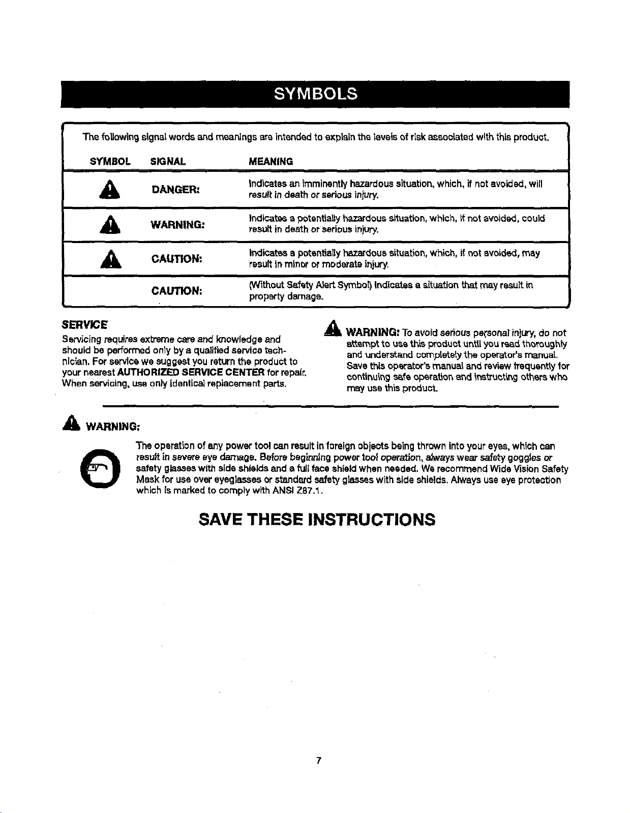
The following signetwords and meanings are intendedto explainthe levels of riskassociated withthis product.
SYMBOL SIGNAL MEANING
DANGER:
Indicatesan imminentlyhazardoussituation,which, if not avoided,will
result indeath or seriousinjury.
A WARNING:
Indi_at_a potentiallyhazardoussituation, which, if not avoided,could
resultin death or seriousin}ury.
CAUTION:
Indir_tas s potentisl{y hazardoussituation,which, if not avoided, may
result in minor or moderate injwy.
CAI_'ION:
(Without Safety AlertSymbot)Indicaies asituationthe.tmay resultin
property damage.
SERVICE
Servicingrequires extremecare and knowledge and
should be performed only by a qualified service tech-
nician. Forservicewe suggestyou returnthe product to
your nearest AUTHORIZED SERVICE CENTER for repair.
When servicing, use on}yidenticalreplacement parts.
_k WARNING" Toavoid seriouspersonal injury,do not
attempt to usethis productuntil youread,thoroughty
andunderstand completely the operator's manual.
Save this operator'smanualand reviewh'equentty for
continuingsafe oparat_onand instructing otherswh_
may use thisproduct.
WARNING:
The operation of any power toolcan resultinforeign objects being thrown intoyour eyes,whichcan
result insevereeye damage. Beforebeginning power tool operaf3on,aJwayswear safetygoggles or
safety glasseswith side shieldsand a fullface shieldwhen needed, WerecommendWide VisionSafety
Mask for useovereyeglassesor standardsafetyglasseswith side shields,Always useeye protection
which is marked to complywithANSI Z87.1.
SAVE THESE INSTRUCTIONS
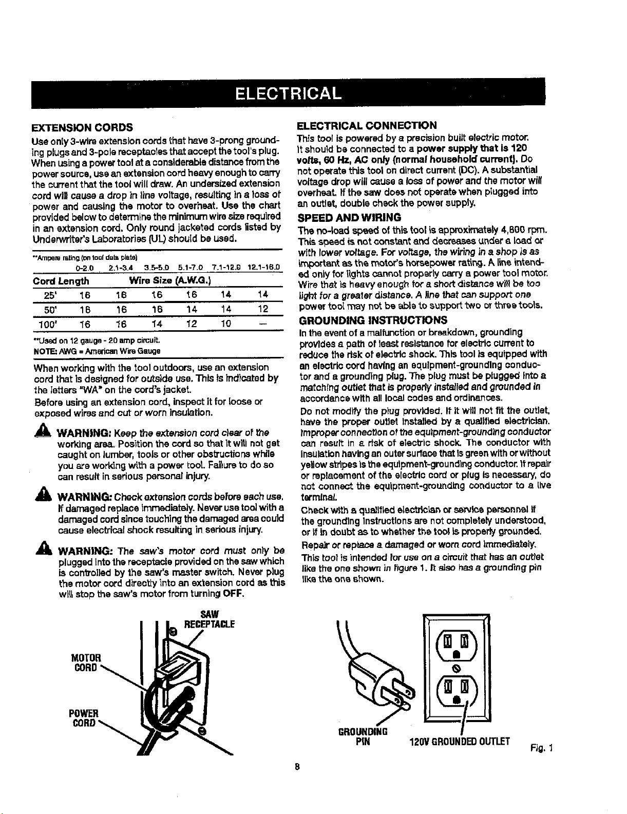
EXTENSION CORDS
Use oniy3-wirs extensioncordst_et have3-prongground-
ingplugsand 3-polereceptaclesthatacceptthetool'splug.
Whenusinga powertoolat a considerabledistancefromthe
powersource,usean extensioncordheavyenoughto carry
the current that thetoolwill draw.An undersizedextension
cord will causea drop in line voltage,resulting in e lossof
power and causingthe motor to overheat. Use the chart
providedbelow to determine the minimum wiresizerequired
in an extension cord. Only round jacketed cordslistedby
Underwriters Laboratories(UL)should be used.
•"Ampere re,ling(on tooldab=plate)
0-2.0 2.1-3.4 3.5-5.0 5.1-7.0 7.1-12.0 12.1-16.0
Cord Length Wire Size (A.W.G.)
25' "_6 16 "_6 t6 14 14
50' 16 16 16 14 14 12
100' 1'6 1'6 1'4 1'2 10 --
-Used on 12 gauge- 20 amp circuPL
NOTE: AWG =American Wire Gauge
When workingwith the too] outdoors, usean extension
cord that isdesignedfor outside use.Thisisindicated by
the letters "WA"on the cord'sjacket.
Before using an extensionoord, inspectitfor loose or
exposed wiresand cut or worn insulation.
WARNING: Keep the extensioncord deer of the
workingarcs. Positionthe cordso thatit willnot get
caughton lumber,toolsor otherobstructionswhile
you areworkingwi.itna powertoot. Failureto doso
can resultin seriouspersonalinjury.
•_ WARNING: Check extensioncordsbel:oreeachuse.
Ifdamaged replaceimmediately.Neverusetoolwitha
damagedcordsincetouchingthedamagedareacould
cause electricalshock resultinginsedousinjury.
,_ WARMING: The saw's motor cord must only be
pluggedintothereceptacleprovidedonthesawwhich
is controlledby the saw's master switch. Never plug
the motor cord d_'ectty"intoan extensioncordas this
wi_stop the saw's motorfrom turningOFF.
SAW
RECEPTACLE
MOTOR
POWER
ELECTRICAL CONNECTION
Thistoo[ ispowered by a precisionbuiltelectricrootor.
It shouldbe connected to a power supply t_at is 120
volts, 60 Hz, A¢ only (normal household currentJ.Do
not operatethis toot on directcurrent(DC).A substantial
voltagedrop willcausea loss of powerand the motor will
overheat, fftha saw does not operatewhen pluggedinto
an outlet, doublecheckthe powersupply.
SPEED AND WIRING
The no-load speed ofthis toolisapproximately 4,800 rpm.
Thissbeed is not constantand decreasesundera load or
with lowervoltage. Forvoltage, thewiringin a shop is as
important as the motor'shorsepowerratlt_. A Lineintend-
ed onlyfor lightsoannot properly carrya powertoolmotor.
Wire thatis heavyenoughfor a shortdis_nce wi!!be too
lightfora greaterdistance.Ailne that can support one
powertool _ay not bs able to support two or three tools.
GROUNDING INSTRUCTIONS
Intheeventof a malfunctionor breakdown,grounding
providesa path of least raslstanoefor electriccurrent to
reducethe riskofelectricshook.]his toolis equippedwith
an electriccord havingan equipment-groundingconduc-
tor and a groundingplug. The plug mustbe plugged intoa
matching outletthat isproperlyinstalledand groundedin
accordancewith all localcodes and ordinances.
Do not modifythe ptugprovided.It It willnot fit the outlet,
have the proper outlet installed by e qualified alectrlalan.
_mpropercanneot_onoftheequipment-groundingconductor
can result in a dsk st electric shock.]'he conductor with
InsulationhavinganoutersurfacethatIsgreenwithorwithout
ye,ow stripesis theequ|pment-groundlngconductor.Itrepair
or replacementofthe electriccordor plug isnecessary,do
not connect the equipment-groundingconductorto a live
terminal
Checkwith a qualifiedelectrlc_n or s_rvicepersonnelff
thegroundingInstructionsare notcompletelyunderstood,
or itin doubt as to whetherthe tool Lsproperbjgrot_nded.
Repair or rsplacaa damaged orworncordImroedtately.
Thistool isintended foruseon a ch'cuitthat hasan outtet
like the one shownin figure 1. Italso hasa groundingpin
llketheoneshown.
8
PIN 120VGROUNDEDOUTLET
FJG.1
Anti-Kickback Pawla (radial arm and table saws)
A device which, when properlyinstalledand maintained,
isdesignedto stopthe wcrkpisee frombeingkicked back
toward the frontof the saw duringa rippingoperation.
Arbor
"Theshaft on whicha brads or cu_}ng tool ismountsd.
Bevel Cut
A cutting operationmade w]ththe blade at anyangle
other than 90° to the table surPace.
Chamfer
A cut removinga wedge from a blockso the end (or part
ofthe and) isangled ratherthan at go°_
Compound Cut
A crossout made with bert1a miter and a bevelangle.
Cross Cut
A cuttingor shap]ngoperationmade acrossthegrain or
thewidth ofthe workpisce.
Cutter Head (planers and Jointera|
A rotatingpiece of ad}ustabla blades. The cutter head
removesmaterial from the warkpiece.
Dedo Cut
A non-throughcutwhich producesa square-sidednotch
or bough inthe workplece (requiresa special blade).
Featharboard
A device used to help centre]theworkplessby guidingit
securelyagainst the table orfence duringanyripping
operation.
FPM or $PM
Feetperminute(orstrokesperminute),usedinreference
toblademovement.
Freehand
Performinga cut without theworkpiecebeingguidedby a
fence, miter gauge, or otheraide.
Gum
A stick'34,sap-based residuefrom wood products.
Heel
Alignmentof theblade to thefence.
Karl
The material removed bythe bladeIna throughcut or the
slot producedby the b!adein a non-throughor partialcut.
Kickback
A hazard thatcan occurwhen the bladebindsor stalls,
throwingthe workplaceback toward operator.
Leading End
"Theend ofthe workp'lecepushed into the toolfirst.
Mltar Cut
A cuttingoperationmade with the workplaceat any angle
tothe bladeotherthan 90°.
Non-Through Cuts
Any cutting operationwherethe blade does not extend
completelythrough the thicknessoftheworkplace,
Push Blocks and Push8ticks
Devices used to feed theworkpiecethroughthe saw
biade duringcutting operations.A push stick(not a push
Mock) shouldbe usedfor narrowrippingoperations.
These aids helpkeepthe operator'shands w_l away frccn
theblade.
Pilot Hole (drillpresses)
A smallholedrilledin aworkpie_ that servesas a guide
for drillinglarge holesaccurately.
Reeaw
A cuttingoperetiento reduoathe thickness ofthe work-
piece tomake thinnerpieces,
Resin
A sticky,sap-basedsubstancethat hashardened.
Revolutions Par Minute {RPM)
The number ofturnscompletedby a spinningobjectin
one minute.
Ripping or Rip Cut
A cutting operationalongme length ofthe work.piece.
Riving Knifa/_prsader/Splittar (table saws}
A metalpiece,slightly thinnerthan the blade, which helps
keep the kerropenanda{sa helpsto preventk.Jckback.
Saw Blade Path
The areaover,under,behind, or infrontofthe blade. As
it applies to the workplece,that area whichwillbe or has
been cut bythe blade.
Sat
The distancethatthetip ofthe saw blade tooth is bent(or
set:}outwardfrom the face ofthe blade.
Snipe (planers)
Depression made at e_her end ofa workplace bycutter
blades when the workplace isnot properlysupported.
Throw-Back
The throwing back ofa worl(plece usuallycaused by the
workplace beingdroppedinto the blade orbeing placed
inadvertentlyincontactwith the blade.
Through SaWing
Any cuttingoperationwhere the blade extends completely
through the thickness of the workplace.
Workplace or Materiel
The itemOnwhichthe operationisbeingdone.
Worktabta
Surfacewhere the work.piecerestswhiteperforminga
cutting,drilling,planbg, orsandingoperation.
g
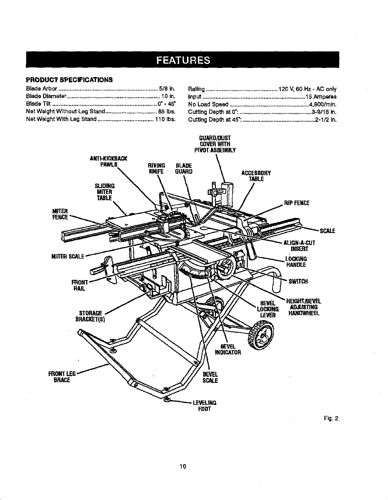
PRODUCT SPECFICATIONS
BladeArbor .............................................................. 5/8 in.
BladeDiameter.......................................................... 10 in.
BladeTilt ................................................................. 0°- 45"
Net Weight Without Leg Stand................................ 85 Ibs.
Net Weight With Lag Stand................................... 110 Ibs.
Rating ............................................. 120 V,60 Hz - AC only
Input ................................................................ 15 Amperes
No LosdSpeed .............................................. -..4,800/rain,
Cutting Depth at 0":............................................. 3-9116 in,
CuttingDepth at 45":............................................. 2-1/2 in,
•AHTI-KICK)BACI[
PAWI.S
SI.IOING
MITER
TABLE
BLADE
GUARD
GUARD/DUST
COVERWITH
PIVOTASSEMBLY
ACCESSORY
TABLE
RIPFENCE
SCALE
ALIGN-A-CUT
INSERT
LOCKING
HANDLE
FRONT
RAIL
STORAGE
DRACI_T(S}
HEIGHT/BEVEL
ADJUSTING
HANDWI_EL
BEVEL
INDICATOR
BRACE
LEVEL|NE
FDDT
Fig.2
10
KNOW YOUR TABLE SAW
See Figure2.
Beforeattempting to usethis product,familiarize yourself
with air operatingfeaturesand safety rules.
ACCESSORY TABLE - The accessorytable may be used
oneitherthe rightor leftside ofthe saw as neededand
has been designedfor usewithsome reuters.A router
mounted on the accessorytable wilrprovideexpanded
capabilitiesfor making rabbets, grooves,chamfers,dove-
tails,and mortiseand tenonjoints.
ADJUSTING CLAMP - Thisclamp looksthemiter fence
stthedesiredcuringangla.
ALIGN-A-CUT INSERT - A plasticinsert onwhichmarks
may be made to indicatethe locationofthe sawcut on
the workplace.
ANTI-KICKBACK PAWLS- Kickbackisa hazard in which
the workplace isthrownbacktoward the operator.The
teethon the anti-kickback pawls point away _om the
workpiece. If the workpiecsshouldbe putisdbacktoward
theoperator,theteeth dlg intothe wood to help prevent
or reducethe possibility of kickback.
BEVEL SCALE - The easy-to-raad scale on the frontof
the cabinetshowsthe exact blade angle.
BLADE - Thissaw isprovided with a 36-tooth, 10 in.
carbideblade.The blade israisedand lowered with the
heightadlustinghandwheeLBevelanglesare lockedwith
the bevel lockinglever.
A
WARNING: Do not use blades rated _easthan the
speed ofthis tool. Failureto heed thiswarning could
resultin personalinjury.
BLADE GUARD - Always keepthe bladeguard down
over the saw blade for through-sawing cuts.
BEVEL LOCKING LEVER -This lever,placedjust under
the saw tablesurfaceon the frontof the cabinet, {coke the
angle settingofthe blade.
HEIGHT/BEVEL ADJUSTING HANDWHEEL - Located
on the front of the cabinet, usethishandwheal to lower
and raisethe bladefor heightadjustmentsor blase
replacement.Thisf_ndwhea( also makes theadjustment
for bevel ang[as easy.
LEG STAND - Attachedto thetable saw base, the leg
stand opens and closeswith ease.
MITER FENCE- The fence attaches totheslidingmiter
table and can be angled for miterand compound miter
cutsas wall as straightcutssuchas cross,bevel cross,
rip,and bevelrip cuts.
MITER GAUGE - The miter gaugealigns thewood for
a cross cut.The easy-to-readindicatorshows the exact
anglefor a miter cut, with positivestopsat 90° and 45°.
MITER GAUGE GROOVES - The miter gauge ridesinthe
grooveson theaccessory table.
MOTOR - The powerfulinductionmotor,withcapacitor
startand V-belt drive, ishousedina sturdysteelbase.
RA]L_ - Frontend rear railsprovidesupport forlarge
workpiecas and the rip fence.
RIP FENCE - A sturdymetal fence guidesthe workplace
and is securedwith the locking handle.Groovesrunalong
the top and sides of the ripfencefor use with optional
clamps and accessories.
RIVING KNIFE/SPREADER - A metalpiece ofthe blade
guard assembly, slightly thinner than thesaw blade,
whichhelpskeep theked open and prevent kickback.
SCALE - Locatedon the front rail, the easy-to-readst;ale
providesprecisemeasurements for dp cuts.
SLIDING MITER TABLE - The mitertable slideseasily
along the miter table base ailowlng the operator to move
the warkpiece acrossthe saw table.
SWITCH/_SEMBLY -This saw hasan easy access
powar switch located belowthe front rm_.To lock the
switch inthe OFF position,removethe switch keyfrom
the sw_tch.Place thekey in e location that is inaccessible
to childrenand othersnot qualifiedtouse the tool
11
OPERATINGCOMPONENTS
The upper portion ofthe blade projectsup throughthe
table and issurroundedby an insertcalledthethroat
prate.The height ofthe bladeissat with a handwhsel on
thefront ofthe cabinet.To accommodatewide panels,
thesaw table hasrailson each side. Detailedinstructions
are providedinthe Opera,on sectionof thisrnanualfor
the basic cuts:crosscuts, miter cuts,bevelcuts, and
compound ¢U_l
The slidingmitertableaseemblyisusedforcrosscutting
operatfens.The miterfenceiseasilyadjustedtocutwood
at an angleby looseningtheadjustingclamp,settingthe
fenceto the miterscale, and retightening the clamp.The
stlding miter table,which restson a basemountedon the
rails,can be repositfehedalong the milsforwide work. _t
can be reversedso the projectingbaseis in the back and
can be moved from the leftside to the rightsideas need-
ed. With _a miter fence removed, themiter table offers
additions]support"for other operationssuchas ripping.
The ripfenceis usedto positionwork for lengthwisecuts.
A scale on the front railshows the distance between the
ripfence and the blade.
it isveryimportantto usethe blade guardassemblyfor all
through-sewingoperations.The blade guardassembly
includes:rivingknife/spreader/splitter, anti-kickback
pawls,and plasticbladeguard.
The saw features a receptacle on the rightsideof the
cabinet that permitsuse of accessories. Use onlyacces-
sories that arelistedfor usewith thistool When usinga
listedaccessory, unplugthe saw motorcordand usathe
receptacleand the saw'-, powerswitchto operatethe
accessory.
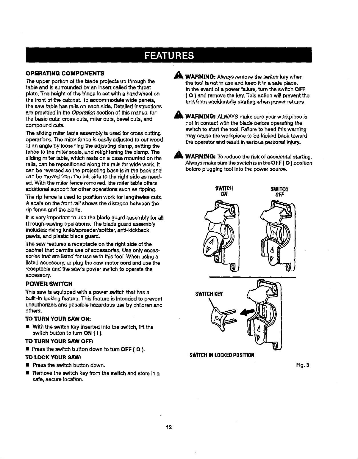
POWER SWITCH
This saw is equipped with a power switchthat has a
built-in locking feature. This feature is intendedto prevent
unauthorizedand possiblehazardoususeby chUdrenand
others.
TO TURN YOUR SAW ON:
• With the switch kay inserted intotheswitch, tiltthe
switch bu_tonto turn ON ( I),
TO TURN YOUR SAW OFF:
• Presstheswitch button down to turnOFF ( O ).
TO LOCK YOUR SAW:
• Press the switch button down.
• Remove the switch kay from the switchand storein a
safe,secure location.
Am, WARNING: Atwaysremove theswitchkay when
the tool L_not m use and keep itin a sate ptsce.
In the event of a power f_zLlure,turn the switchOFF
( O ) 8.ridremovethe key.Thisaction will preventthe
tool _romaoc_dsntaltyst_tln 9 when powerreturns.
_' WARNING: ALWAYSmake sureyourworkpisce is
not in contactwith the b(adebeforeopsrat(ng the
switchto startthe tool. Faitureto heed this warning
may cause the workpiecato be kicked back toward
theoperatoraridresultit_serious_rsor_iinjury.
_lz WARNING: Toreduce theriskof accidental starting,
Alwaysmakesurethe switchis intheOFF ( O ) position
before pIuggingtoolintothepowersource.
SWTfCH SWITCH
ON OFF
SWITCHKEY
SWITCHINLOCKEDPOSITION
Fig. 3
12
BLADES
Formaximum performance,it isrecommendedthatyou
usethe Craftsman36-tooth, 10 in.carbide combination
bladeprovidedwith yoursaw.Additionalblade stylesof
the same high qualityare availablefor specificoperations
suchas ripping.Yourlocaldealercan provideyouwith
complete information.
A WARNING: Do notuse bladesrated less than the
speed ofthistool. Faitureto heed this warningcould
resultin personalinjury.
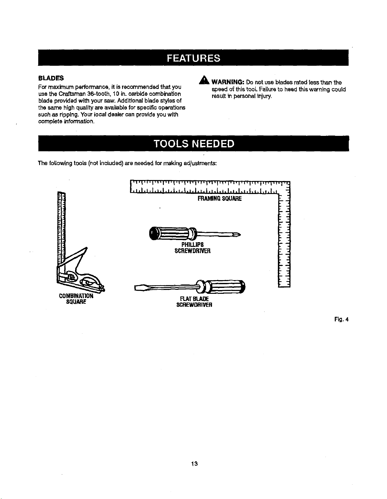
The f#,lowing toots (notinoLudsd)are needed,for makingadiustments:
COMBINATION FLATBLADE
SQUARE SCREWDRIVER
Fig. 4
13
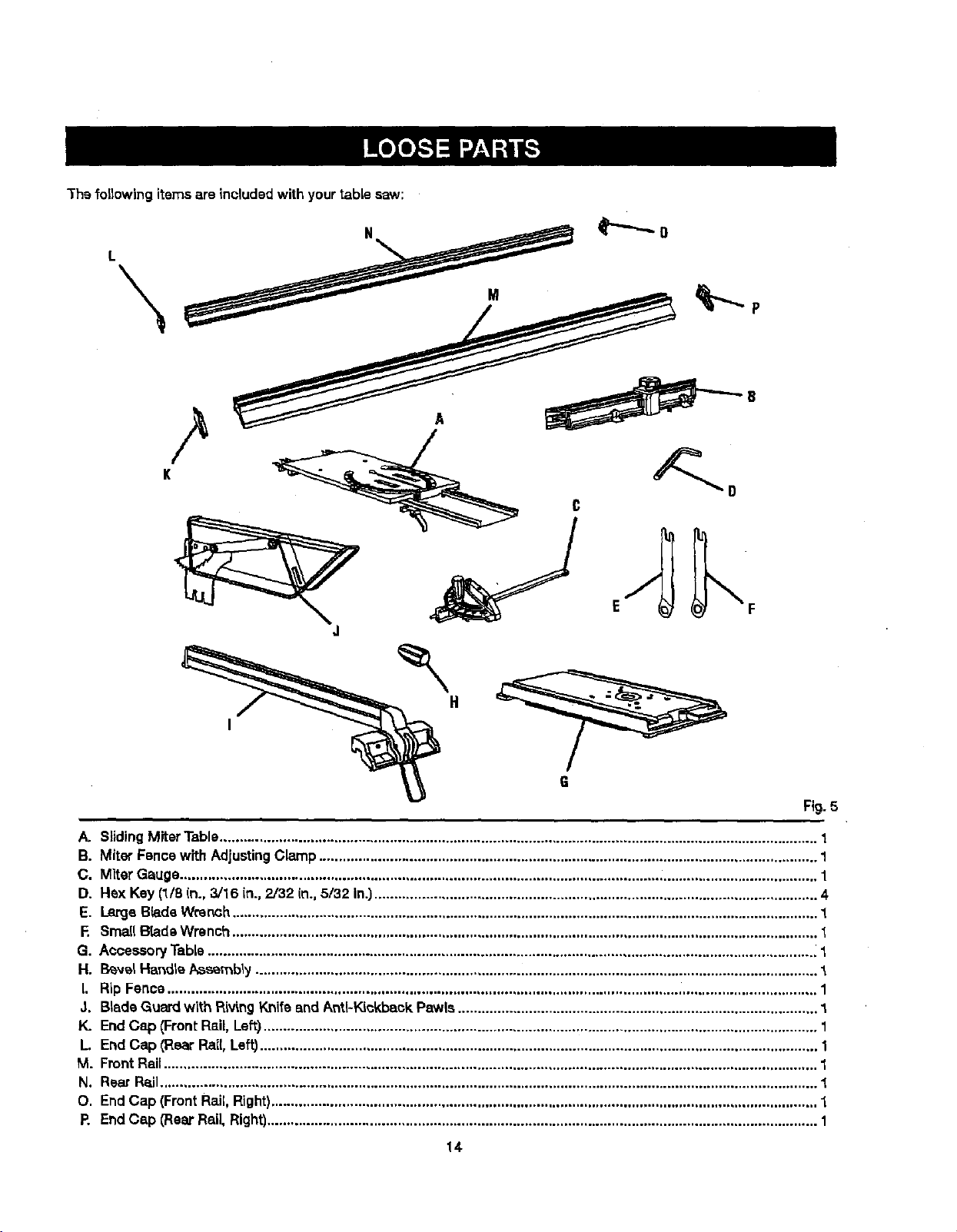
Thefollowing itemsareincludedwith yourtable saw:
G
Fig. 5
i
A. SlidingMiterTable....................................................................................................................................................... 1
B. Miter Fancewith AdjustingClamp.............................................................................................................................. 1
C. MiterGauge......................................................................................................................... ........................................ 1
D. Hex Key (1/8 In., 3/16 in., 2/32 (n.,5/32 In.)................................................................................................................ 4
E. Large BtadaWrench.................................................................................................................................................... 1
E Small B[adeWrench ....................................................................................................................................................
G. AccessoryTable.......................................................................................................................................................... 1
H. I_vel HartdleAssembly.............................................................................................................................................. 1
I. RipFence .................................................................................................................................................................... 1
J. BladeGuard with RivingKnifeand Anti-Kickback Pawls........................................................................................... 1
K. EndCap {Front Rail, Left)............................................................................................................................................ 1
L End Cap (Roar Rail,Left)............................................................................................................................................. 1
M. FrontRail..................................................................................................................................................................... 1
N. Rsar Rail..................................................................................................................................................................... 1
O. EndCap (FrontRail,Right).......................................................................................................................................... 1
P. EndCap (RearRail, Right)........................................................................................................................................... 1
14-
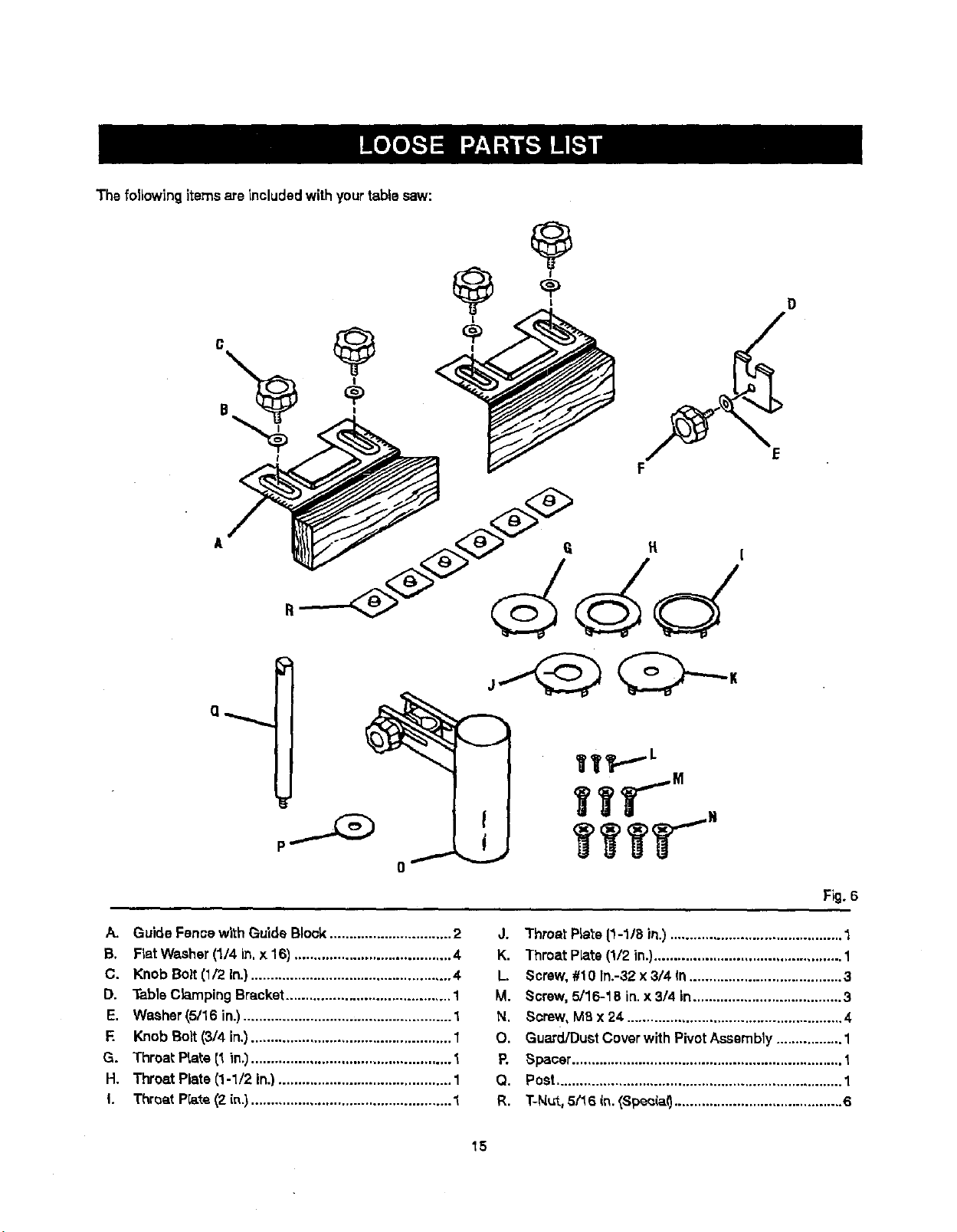
Thefolidwing itemsare includedwith yourtablesaw:
@
D
F
d
Fig. 6
A. GuideFence w_thGuide Block............................... 2
B. FlatWasher(1/4 in.x 16) ........................................ 4
C. Knob Bolt(1/2 In.)................................................... 4
D. TableClampingBracket.......................................... 1
E. Washer(5/16 in.)..................................................... 1
F. Knob Bolt(3/4 in.)................................................... 1
G. Throat Prate(1 in._................................................... 1
H. Throat Plate (1-1/2 in.)............................................ 1
I. Throat Prate(2 its.)................................................... 1
J. Throat PLate[1-1/8 in.)............................................ 1
K. Throat Plats(1/2 in.)................................................ 1
L. Screw,#10 In.-32 x 3/4 In....................................... 3
M. Screw, 5/16-18 in.x 3/4 in...................................... 3
N. Screw, M8 x 24 ....................................................... 4
O. Guard/DustCoverwith PivotAssembly................. 1
P. Spacer..................................................................... t
Q. Post......................................................................... 1
R. T-N_t,5(16 in._Spec(a0........................................... 6
15
UNPACKING
Thisproduct requiresassembly.
• Carefullyliftthe asw from the cartonand place iton a
level work surface.
NOTE=This tool is heavy.To avoidback injury,keep
yourknees bent and liftwithyourlegs, notyourback,
and do not liftsaw without help.
• Inspect the tool carefullyto make sure no breakageor
darnags occurredduringshipping.
• Do not discardthe packingmaterial untilyou have
caref_Jttyinspected and sstistacto_tyoperated the too_.
• The _aw isfactory setfar accurate cutt'_ng.After
assemblingit, checkfor accuracy.If shippinghas
influenced _e settings,referto specificprocedures
expta'medin_is manual.
• If any parts aredamaged or missing, plasea call
1-800-932-3188 for ass]stance.
_" WARNING: if anyparts are missing,do not operate
th_stoo_unt_the missing parts are replaced.Failure
to do so could rssultin possibleseriouspersonal
injury.
_1= WARNING: Do not attempt to modify this tool
or create accessories not recommendedfor use
with this tool. Anysuch aiteratlonor modification is
misuseand could resultin a hazardouscondition
leading to possible se_oL;spersonalin)ury.
A WARNING: Do not connectto power supplyuntil
assembly is complete. Fa(lursto comply couldresult
in accidentalstarting and possibleseriouspersonal
injury.
_1= WARNING: Do not liftthe saw without help. Hold
it close to your body.Keep yourkneesbent and
(iftwith yourlegs, not yourback. Ignoringthese
precautionscan resultin back injury.
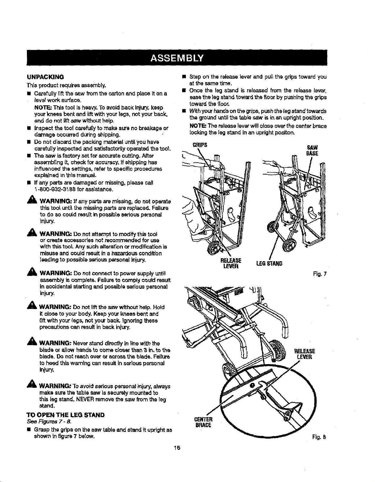
• Step on the release]everand pull the gripstoward you
at the sametime.
• Once the leg stand is released from the release lever,
easethe leg s_n rttoward the _ocr by pashlngth_ grips
toward the floor.
• Withyourhandsonthegr_ps, pushthslegstand_owards
the ground untilthe _.bis saw isin an uprightpos'_tion.
NOTE: The releaseleverwillclose overthe centerbrace
lockingthe legstand in an uprightposlton.
GRIPS SAW
BASE
RELEASE LEG,STAND
LEVER
Fig. 7
A
Am, WARNING: Never stand d}rs_')yinlinewith the
blade or allow handsto cornscloser than 3 in.to the
blade. Do not reach over or across the blade. Failure
to heed this warning canresultin seriouspersonal
iniury.
A
me, WARNING" Toavoid seriouspersonalinjury, always
make sure the table saw is securelymountedto
this leg stand. NEVERremove the saw from the 1eg
stand.
TO OPEN THE LEG STAND
See Figures7- 8.
• Grasp the gripson the saw table and s_andituprightas
shown infigure 7 be(ow.
cENTER
BRACE
Fig,8
16
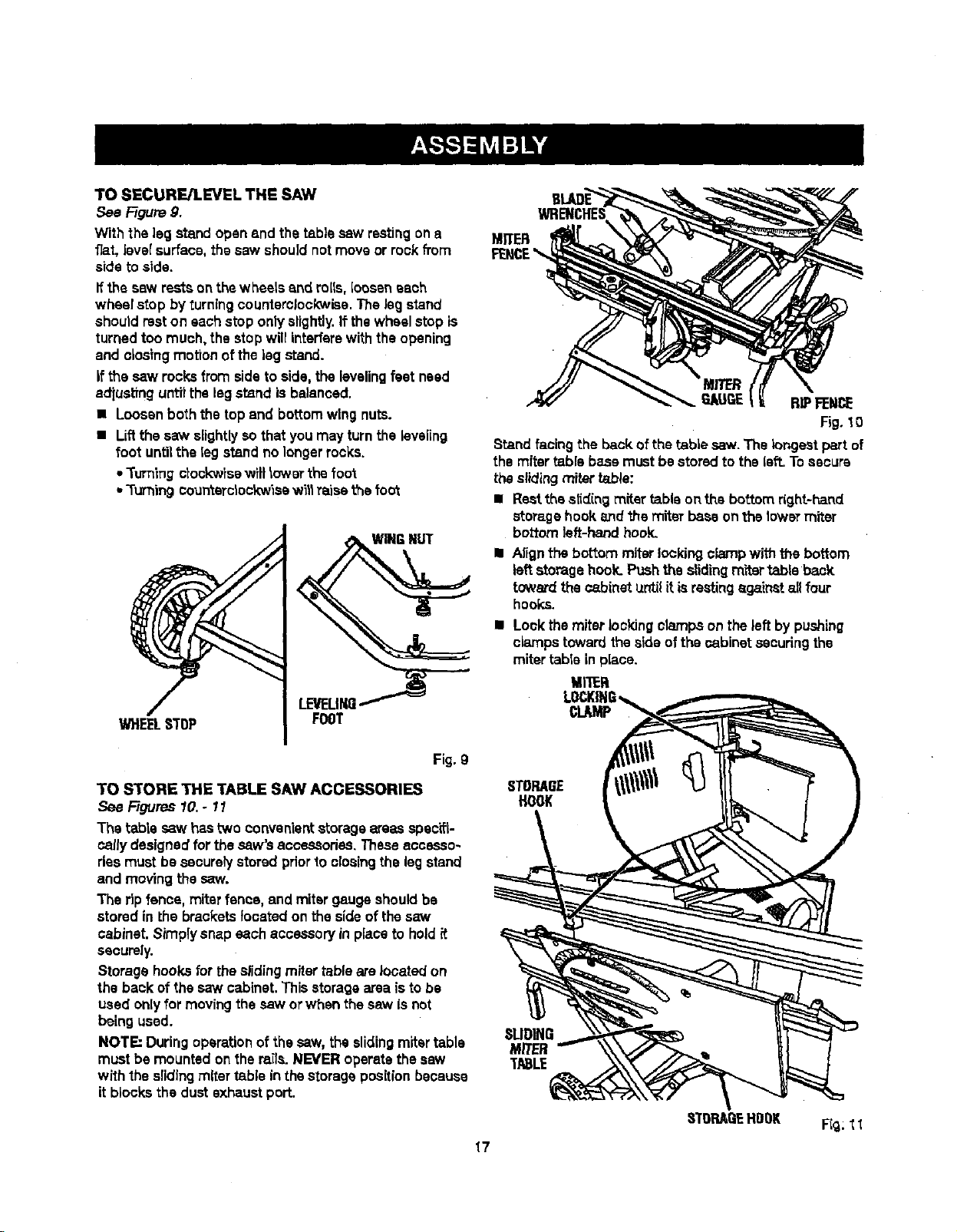
TOSECURE/LEVELTHESAW
See F-igum9.
With the leg stand openand the table saw restingona
fiat, levelsurface,thesaw shou]dnotmoveor rookfl'om
side to side.
ffthe sew restsonthe wheels and roils,[oosaneach
wheel stop by turning counterclockwise.The legstand
shouldmet on eachstop onlyslightly.If thewheel stop is
turnedtoo much,the stop willinterferewiththe opening
and closing motionofthe leg stand.
ifthe saw rocks fromside toside, the levelingfeet need
adiustlnguntilthe leg stand is balanced.
• Loosen boththe top and bottomwing nuts.
• Liftthe saw slightlysothat you may turnthe kiveiin9
foot untilthe leg stand no longerrocks.
• Turning ctookwise wilt lower thefoot
•Turningcountarclockwisaw_llra'lsathe fog
WINGNUT
FOOT
Fig. g
TO S'fORE THE TABLE SAW ACCESSORIES
See Figures10.- 11
The table saw hastwo convenientstorage areasspecifi-
callydesigned for thesaw's accessories. Theseaccesso-
ries mustbe sooure_ystoredpriorto closing the legstand
and moving the saw.
The ripfence, miter fence, and miter gaugeshouldbe
storedin the bracketslocatedon the sideof thesaw
cabinet. Simplysnap each accessoryin place to hold_t
securely.
Storagehooksfor theslidingmiter tableare located on
the back of thesaw cabinet. Thisstoragearea isto be
used onlyfor movingthe saw orwhen the saw is not
being used.
NOTE: Duringoperationofthe saw, the slidingmitertable
mustbe mounted onthe mile.NEVER operatethesew
with the slidingmiter table in thestoragepositionbecause
it blocksthe dust exhaustport.
MZTER
RIPFENCE
Fig. 10
Stand facing the backofthe table saw. The longestpart of
themiter table base must be storedto the left.Tosecure
theslidingmiter table:
• Restthe slidingmiter table onthe bottomright-hand
storage hookand +,hemiter baseon thelowermiter
bottomleft-hand hook.
I Alignthe bottom miterlookingcfe_npwith the bottom
leftstorage hock. Pushthe slidingm'rtertable back
towardthecabinet _zntilit isrestingagainst allfour
hooks.
• Look themiter lookingclampson the leftby pushing
clampstowardthe sideof the oabinst securingthe
mitertable in place.
MI'IER
STORAGE
HOOK
SLIDING
MITER
TABLE
STOP,ABEHDDK
F_g;11
17
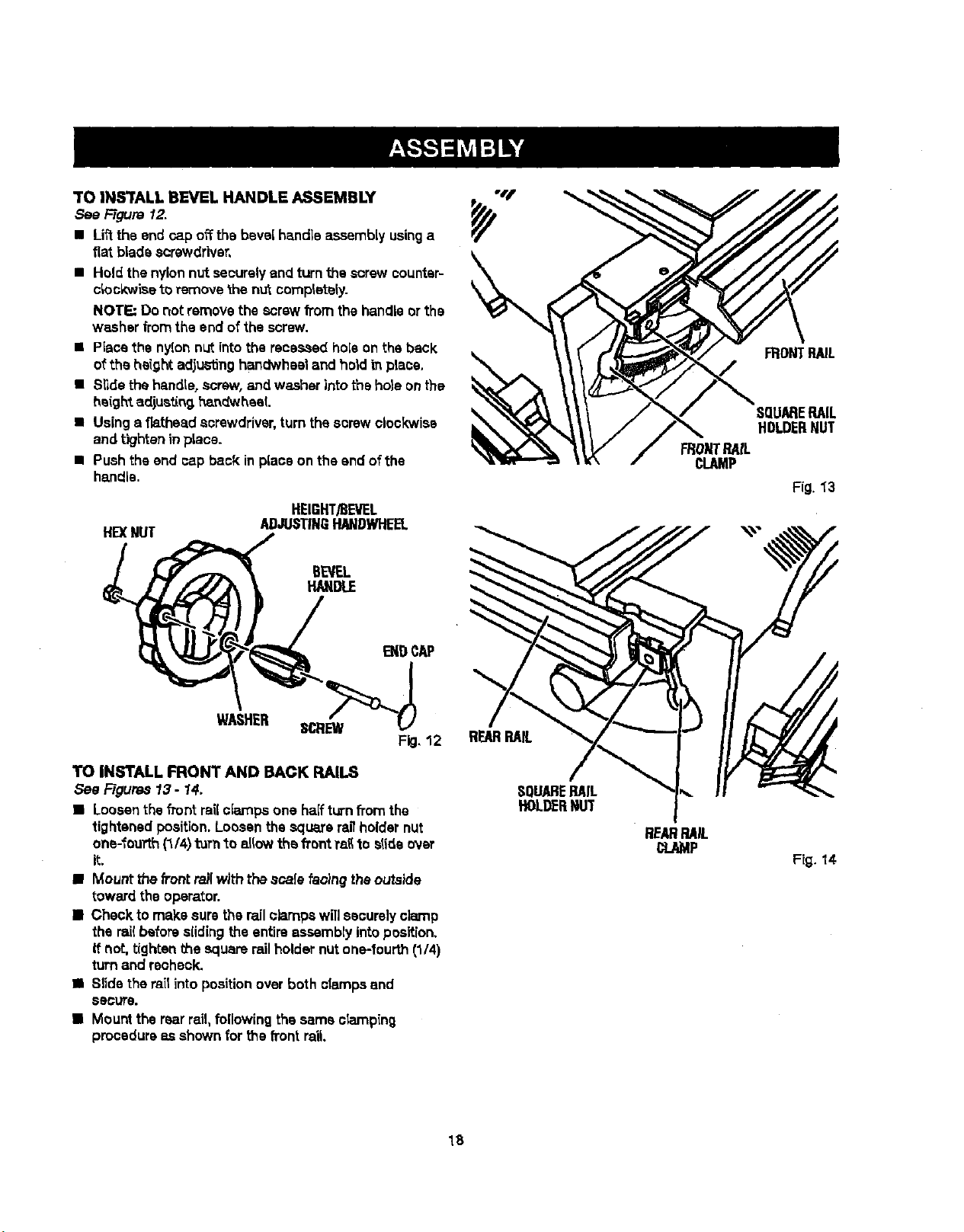
TO IN_rALL BEVEL HANDLE ASSEMBLY
See F-t_re 12.
• Liftthe end rap offthe bevel handle assembly usinga
fiat b|ade screwdriver,
• Hold the nylonnut securelyand turnthe screw counter-
clockwise toremove thenutcompletely.
NOTE: Do not remove the screwfrom the handleor the
washer fromthe end ofthe screw.
• Placethe nylonnut intothe recessed holeon the back
ofthe height adjustinghandwheeland hold in place,
• Slidethe handle,screw, and washer intothehole onthe
he(ghtadjustln9l_n_'_heaL
• Usinga fiatheadscrewdriver, turn thescrewclockwise
and tighteninplace.
• Pushthe end cap back inplace on the end of the
handle.
HEXNUT
HEIGHT/BEVEL
ADJUSTINGRANDWHEEL
WONTRAIL
cLAMP
FRONTPAIL
SQUARERAIL
HOLDERNUT
Fig. 1"3
BEVEL
HANDLE
WASHER
TO INSTALL FRONT AND BACK RAILS
See Figures13 - 14,
• Loosenthe frontrailciarnps one halfturnfi'omthe
tightenedposition.Loosenthesquare ragholdernut
one-fourth(1/4)turn"_oallowthe front ra_to slide ovsr
it.
• Mount the _ontrailwith thescale faoincj theoutside
towardthe operator.
• Check to make sure the railclamps willsecurelyclamp
the rai(beforeslidingthe entireassembly intoposition.
If not, tighten the squarerailholdernutone-fourth(1/4)
turnand recheck.
• Slidethe railintoposition over both clampsand
secure.
• Mount the rearrail,following the same ciamping
procedureas shownfor the front rail
SQUARERAIL
HOLDERNUT
REARRAIL
CLAMP
Fig. 14
18

TOUNLOCK/MOVETHERAILS
See Figure 15.
The front and backrails will needto be positionedsothey
do not touch thefloor when the Sagstand isclosed.
Usingthe bottomscaleas a guide,the scalewill need to
bealigned to the saw blade at the 14 in.mark.To unlock
and move t_e mils:
• Loosenthe front rali clampsby pushingthe levertothe
left.
• Slidethe ra'dto the desired position.
• Securethe ragin positionbypushingthe clampto the
right.
• Repeat shove steps with therear railplscingit inthe
same locationas thefrontrail.
NOTI:-'Whenthe rails are moved tothe right,usecaution
toavoid trippingon the front legbrace.
RELEASE
LEVER
IL
CLAMP
_g. 15
TO CLOSE THE LEG STAND AND MOVE THE SAW
See Figure16.
Store theslidingmiter table on the back ofthesaw
cabinet. See To Store the Tab/eSaw A_ssories on the
previouspage. Next, set the frontand back ransto14 in.
as describedabove.
NOTE: Never closethe legstand orattempt to movethe
table saw untilboththe above stepsare complsted.
To cfoae the leg stand:.
• At the same time, step onthe releaselever,graspthe
grips,and t_ the handlesop and away fromthe body.
• Push the table saw untilthe releaseleverclicksand
locks intoplace.
To moYa the |eg s_and;
• Holdingthegripsfirmly,pu(tthe handlestoward
you untUthe lag stand and saw are balanced on the
wheels.
• Push thesaw to the desiredlocationthen eitheropen
the lag standfor immediatesaw operationor storethe
saw in a dry environTnent.
NOTE: Never movethe table saw unlesstheslidingmiter
table issecurely stored.
Fig.16
TO REMOVE / REPLACE THE THROAT PLATE
,..%eFigure 1.7,
• Raisetheblade 2 in.above the saw table.
• Loosentha screwsinthe throat prate.
• Liftthe throatplate from the saw,
• Toreinstallthe threatplate,af(gn theholesin the throat
platewiththe holesin the saw table.
• Ratightenthe screws, beingcarefulnot to overt_ghtan,
which can causethethroat plate tobow or bend.
19
Fig.17
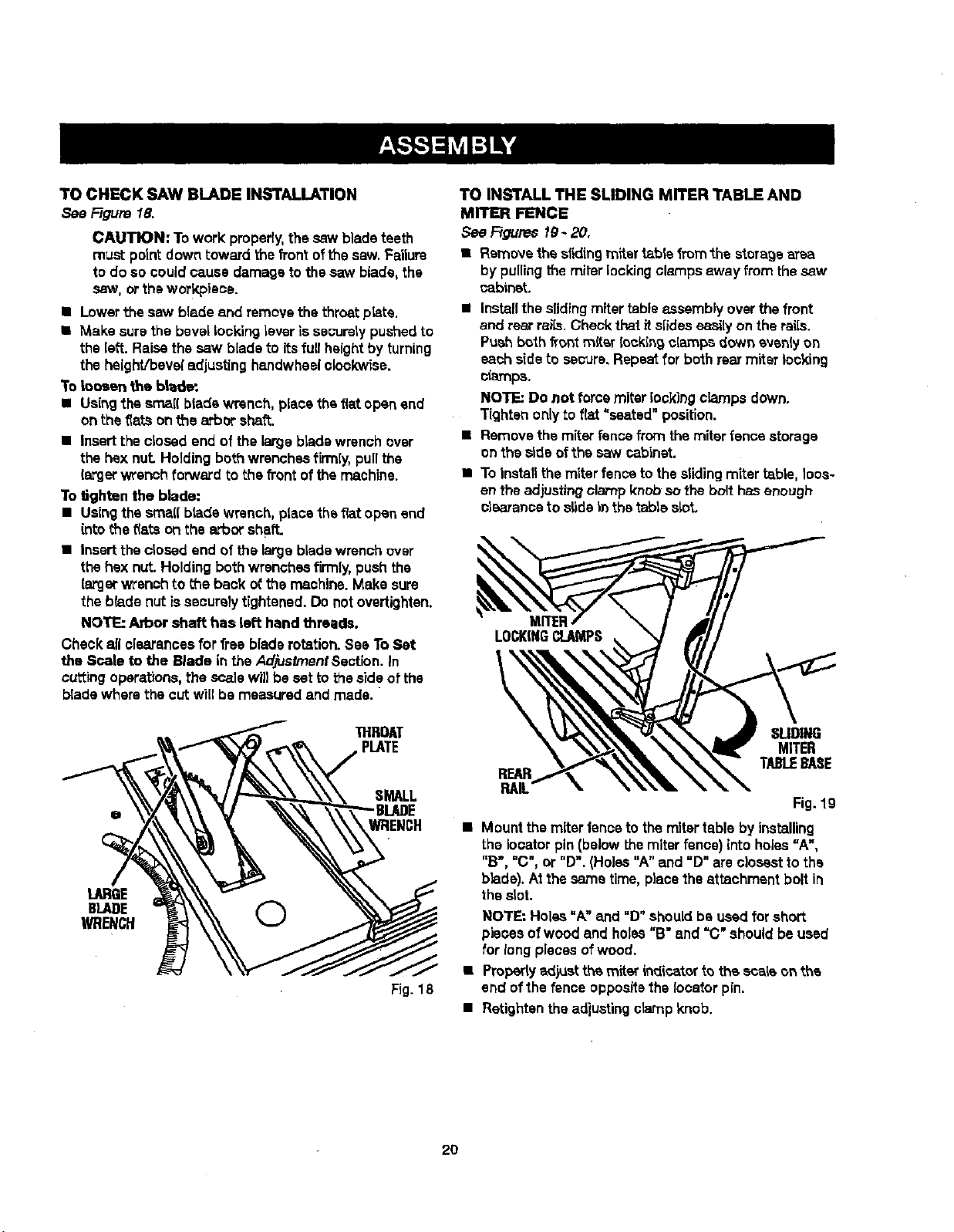
TOCHECKSAWBLADEINSTALLATION
See Figure 18.
CAUTION: Towork:properly,the saw blade teeth
must pointdown toward thefrontoft'nesaw.Failure
to do so could cause damage to thesaw blade,the
saw, ortheworkpisce.
• Lowerthe saw blade and remove the throat p_te.
• Make surethe bevel Locking lever issecurelypushed to
the left. Raise the saw blade to its fu[I height by turning
the height/bevel adjusting hsndwheel clockwise.
To Loosen the blade.
• Using';hesmall bladewrench, place theflat openand
on the fiats on the arbor shat'_.
• Insertthe closed end of the large blade wrenchover
the hexnut Holdingbothwrenchesfirmly, pull the
largerwrenchforward to the front of the machine.
To *dghtenthe blade:
• Usingthe srnaflbradswrench, placethe flatopenend
(rite the _(atson the arbor shaft.
• Inserttheclosed end of the largebladewrenchover
the hex nut.Holdingbothwrenchesfirmly,pushthe
{argerwrench to the back ofthe machine.Make sure
the blade nut issecurelytightened. Do notovsrtighten.
NOTE: Arbor shaft has left hand threads.
Check all clearancesfor free bladerotation.See ToSet
the Scale to the Blade in theAdjustmentSection. In
cutting operations,the scalewil}beset to the sideof the
bladewhere the cut willbe measured and made.
THROAT
PLATE
SMALL
WRENCH
LARGE
BLADE O
WRENCH
Fig. 18
TO INSTALL THE SLIDING MITER TABLE AND
MITER FENCE
See Figures fg- 20,
• Removethe slidingrofter table from the storagearea
by pullingthe miter lockingclampsaway from thesaw
¢ablnst
• Installtheslidingmitertable assembly overthe front
and rear rails. Checkthat itslides easilyon the rsi[s.
Push both frontmiter looking clamps down evenlyon
eachsideto secure, Repeat for bothrear miter locking
_arnps.
NOTE: Do not force miter look}rig clamps down.
Tightenonlyto f_t "seated" position.
• Remove themiter fence from themiter fence storage
onthe side ofthe saw cabinet.
• To installthemiterfence tothe slidingmiter table, Ices-
en theadjustingclamp knobso the bolt hasenough
olsaranoa to slide _nthe table slot,
LOCKINGCLAMPS
REAR
RAIL
SUDII_
MITER
TABt.EBASE
Fig. 19
Mount the miter fenceto the mitertable by installing
the locater pin(belowthe miter fence) into holes=A",
"B", =C",or "D". (Holes"A" and =D" areclosest1othe
b}ade).Atthe same time, placethe attachment bolt in
thes_ot.
NOTE: Holes =A" and "D"shouldbe used for short
pieces of wood and holes"B" and "C" shouldbe used
for long piecesof wood.
• Property a_}ustthe miter indicatorto the scale on the
end ofthe fence oppositethe locater pin.
• Retightantheadiustingctarnp knob.
2O
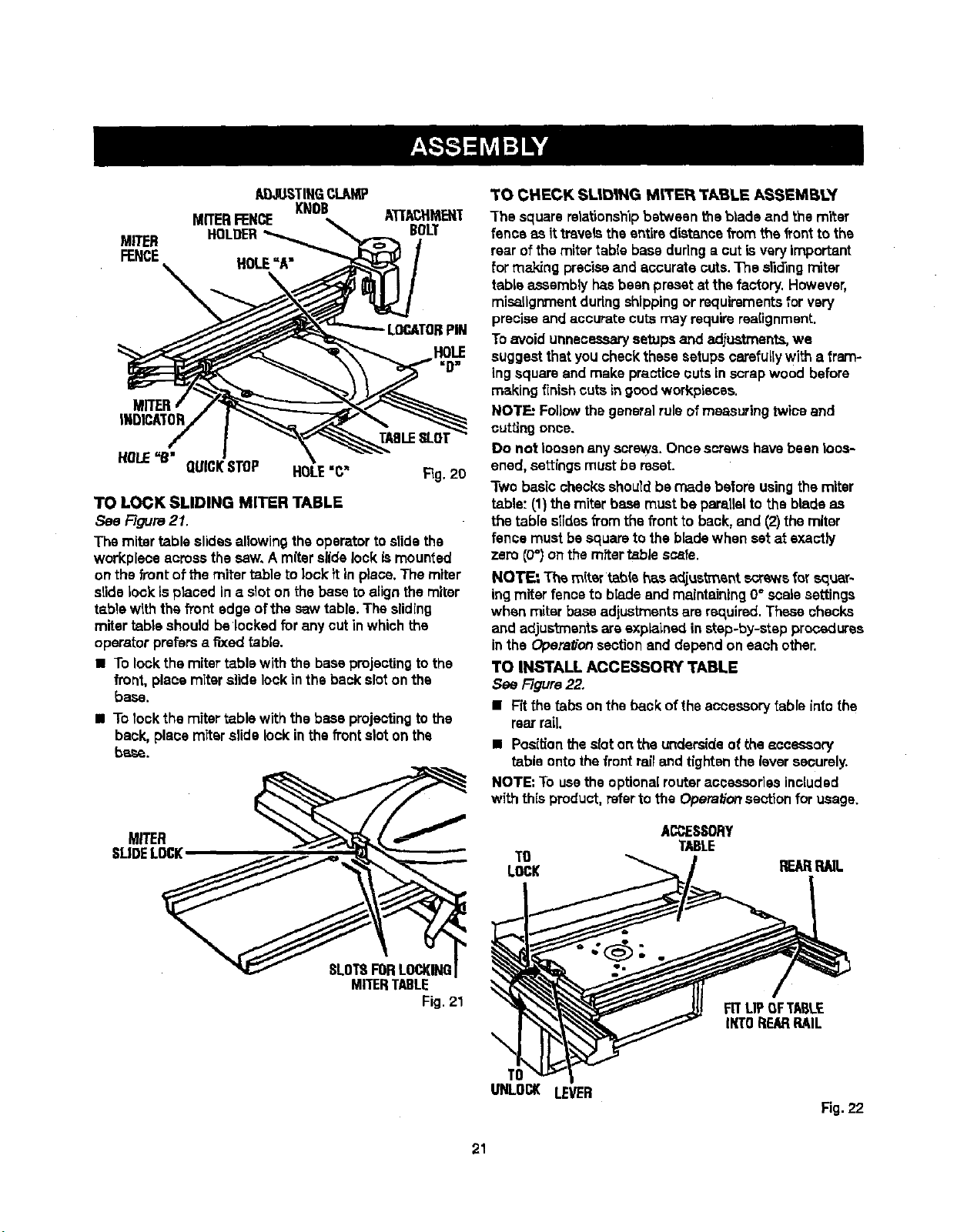
I!_STIIIG CI_II,N[P
MITERFENCE KNOB ATI'ACHMEN'T
MITER HOLDER BOLT
FENCE
HOLE"A"
\ ,
LOCATORPiN
INDICATOR
TABLESLOT
HOLE=B"
QUICKSTOP HOLE"C" Fig.20
TO LOCK SLIDING MITER TABLE
See Flours21.
The mitertable elides allowingthe operatorto elidethe
workplsce acrossthe saw,A miterslidelock ismounted
on the front of the miter table to lock it inplace.The miter
slidelock is placed ina slot on the baseto align themiter
tabla with theh'ont edge ofthe saw table. The sliding
miter table shouldbe locked for any cutinwhichthe
operatorprefersa fixed table.
• To lock the miter table with the baseprojectingtothe
front, place miterslide lockin the backslot onthe
base.
• To lockthe miter table with the base projectingto the
back, place miter slide lockin thefront slot on the
base.
MITER
SLIDELOCK
TO CHECK SL|D|NG M_'ER TABLE ASSEMB!3/'
The square relationshipbetween theblade and the miter
fence as it travels the entire distancefrom thefrontto the
rear ofthe miter table baseduringa cutisvery important
for m_ng preciseand accurate cuts.The slidingmiter
table assemblyhasbeen presetat the factory. However,
misallgnment duringshippingor requirementsfor very
preciseand accurate cutsmay requirerce[ignment.
To avoidunnecessarysetups arid ad.iuatments,we
suggestthatyou checkthesesetups carefullywith a fram-
ing square and make practicecuts inscrapwood before
making finishcuts ingood workpisces.
NOTE: Followthegeneralrule ofmeasuring twice and
cuttingonce.
Do not loosen any screws.Once screwshavebeen loos-
ened, settings mustbe reset.
Two basic checks shouldbe made before usingthe miter
table"(1) themiter base must be parallelto the bladeas
the table slides fTomthe front to back, and (2)the miter
fence mustbe squareto the blade when set at exactly
zero (0")on therafter table scats.
NOT_ The miter tablehas adjus_ant screwsfor squar-
ingmiter fence tc bladeand maintaining0° scalesettings
when miterbaseadjustments arersc,uired.These checks
and adjus't_entsareexp_ined in step-by-step procedures
inthe Opera#onsectionend depend on each other.
TO INSTALL ACCESSORY TABLE
See Figure22.
• Fit the tabs on theback of theaccessorytable intothe
rear rail.
• Posi_onthe sloton the undersideof the accesaory
table ontothe frontrailand tightenthe lever securely.
NOTE: To usetheoptionalrouteraccessories included
with this product, refertothe Operationsectionfor usage.
ACDESSORY
TABLE
TO
LOCK REARRNL
SLOT8FORLOCKING
MITERTABLE
Fig. 21
\
TO
UNLOCK
LEVER
FITUP OFT_B,LE
IKTOREARRAIL
Fig. 22
21
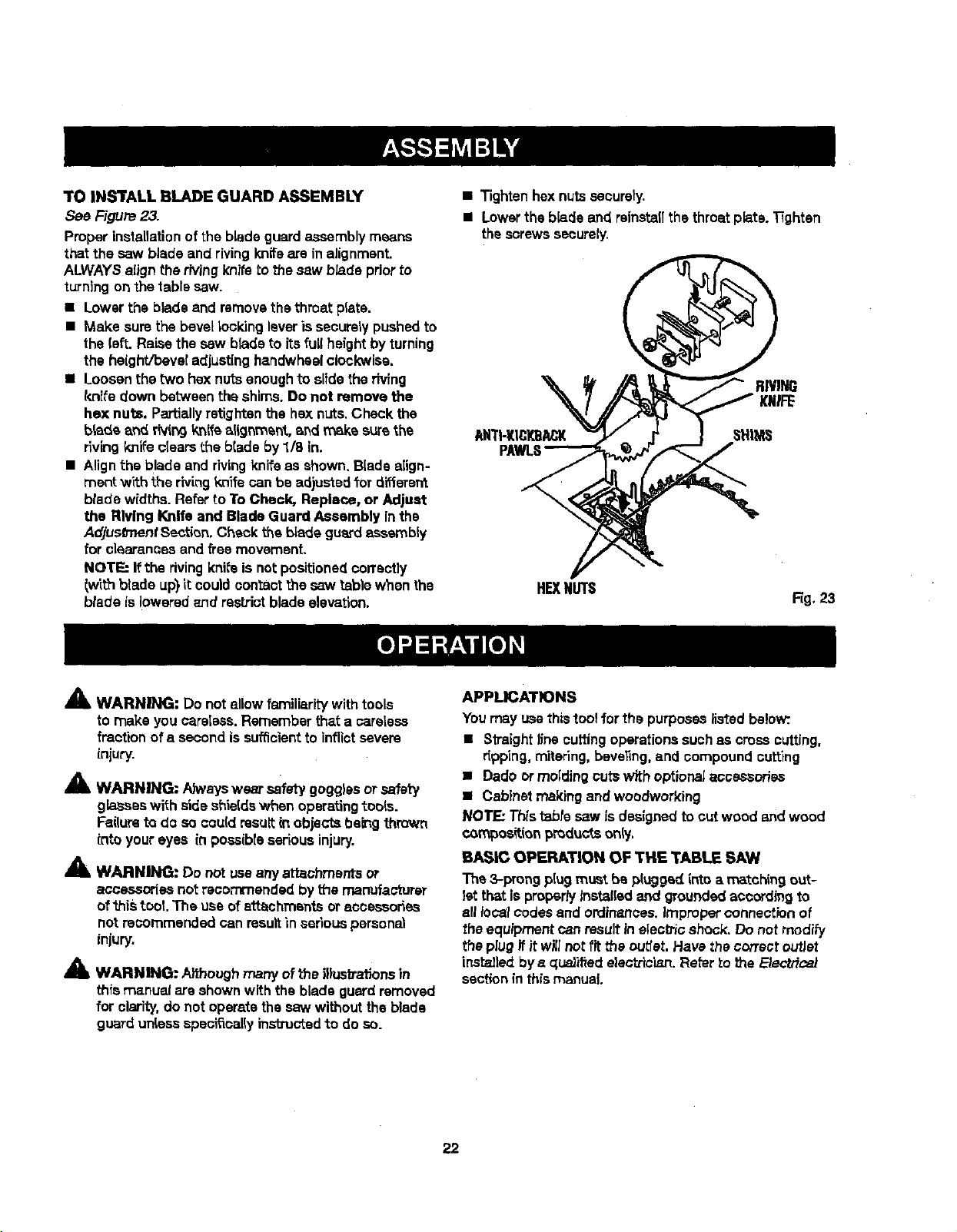
TOINS'i'ALLBLADEGUARDASSEMBLY
See Figure23.
Proper installationof the blade guardassemblymeans
that the saw blade and rivingknifeare in alignment.
ALWAYSalign the rivingknife to the saw b/ade priorto
turning on the table saw.
• Lower the bladeand removethe throatplate.
• Make sure the bevellooldng leveris securelypushedto
the (eft.Raise the saw bladeto its full heightby turning
the height/beveladjustinghandwheelclockwise.
• Loosen the two hexnutsenoughto slidetheriving
knife down between the shims.Do not remove the
he]<nuts. Partially retightenthe hex nuts,Check the
blade and r(vin9knife alignment, _nd mska surethe
rlvingknifeclears the blade by 1/8 in.
• Alignthe blade and rivingknife as shown. Bladealign-
merit with the rivingknife canbe adjustedfor diffarard
blade widths.Refer 1oTo Cheek, Replace, or Adjust
the Riving Knife and Blade Guard Assembly inthe
AdjusO'nentSection, Check the bladeguardeseambiy
for clearances and freemovemanL
NOTE: Ifthe rivingknife is notpositionedcorrectly
lwtth blade up) it couldcontact the saw table when the
blade islowered znd rastJ'ictbladeelevation.
• Tightenhexnutssecurely.
• Lowerthe blade and reinstaflthe throatplate.Tighten
thescrewssecurely.
RIW_
ANTI-KICKBACK SHIMS
H_N_S
Fig. 23
A
41L WARNING: Do not allowfamiliaritywith tools
to make you careless. Remember thata sarelese
fraction of a secondissuf_cfentto inflictsevere
injury.
A
i WARNING; Ah_,ayswest safety gogglesor safer7
gbsses with side shieldswhen operatingtools.
Failureto do socould resultin objects being thrown
intoyoureyes in posaibieserious injury.
_lk WARNING: Do not usaanyattachments or
accessories not recommended bythe manufacturer
of'ibis tool. The use ofattachments oraccessories
not recommendedcan resultin serious personal
injury.
A
WARNING: Aifhough many of the illustrat;ons in
this manual are shown with the blade guard removed
for clarity, do not operate the saw without the blade
guard unless specifically instxucted to do so.
APPLICATIONS
Youmay usethistoolfor the purposeslisted below:.
• Straight linecuttingoperationssuchas cross cutting,
r_pping,mitering,beveling,and compound cutting
• Dado ormolding outs with optionalaccessories
• Cabinet makingand woodworking
NOl'F.: Thistable saw Jsdesignedtocut wood and wood
compoe_i_nl:_mdu_sonly,
BASIC OPERATION OF THE TABLE SAW
The 3-prongp[ugmust be plugged into a matchingout-
let that is propertylnst_fled and groundedaccording to
all focalcodesand ordinances.Improper connectionof
the equipmentcan resultin elec_c shock. Do not modify
the plugif it willnot.fit the cuber.Have the correctoutlet
inst_led bye qus)ified electrician.Refer to the E}ectric_
sectionin this manual.
22
CAUSES OF KICKBACK
Kickbackcan occurwhen theblade stallsor binds,kick-
ingtheworkpieca backtowardyouwith greatforce and
speed. If yourhandsare near the saw blade, theymay
be jerked loosefromthe workpieceand may contactthe
blade. Kickbackcancause seriousinjury.Use precautions
to avoidthe risks.
Kickback can be caused by any actionthatpinchesthe
blade in the wood such as:
• Making a cutwith incorrect blade depth
• Sawlnginto knots or nailsin theworkpiece
• Twistingthewood while makinga out
• Failingto supportwork
• Forcinga cut
• Cuttingwarped orwet lumber
• Us{ngthe wrong blade for thetype of cut
• Not following oorrect operatingprocedures
• Misusingthe saw
• Failingto usethe an_-kick.baokpawls
• Cuttingwith a dull, gummed-up, or h'npmperiy set
b_ad_
AVOIDING KICKBACK
• Always use the correctblade depth setting.The top of
the blade teeth shouldclearthe workpieceby 1/8 in. to
114in.
• Inspect the work for knotsor nailsbeforebeginninga
cut KnocY,out any loose knotsw_tha hamme_'.Never
saw into a loose knot orna|(.
• Always usethe ripfencewhen ripcuttingand themiter
gaugewhen crosscutting.Thishelpspreventtwisting
thewood inthe cut.
• Always use cLsan,sharp, and properly-setblades,
Never make outs with dullblades.
• TOavoid pinchingthe blade, supportthe work properly
beforebeginninga cut,
• When making a cut. usesteady,evenpressure.Never
force outs.
• Do not cutwet orwarped lumber.
• Always herdyourworkplece fLrmtywith both hands or
with pushsticks.Keep yourbodyin a balanoed posi-
tionto be ready toresist kickbackshouldit occur.
Never stand direc_yin line withthe blade.
• Use the righttype of blade for the cutbeing made.
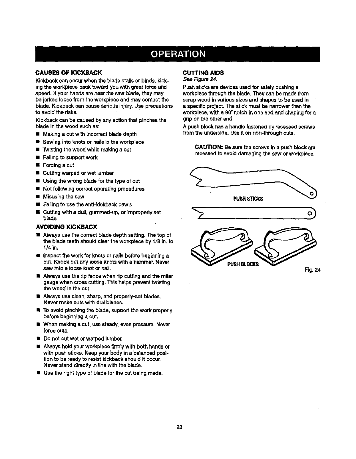
CUTTING AIDS
See Figure 24.
Pushsticksare devicesused for safelypushinga
workpLscethroughthe blade.They can be made _'orn
scrapwood invarioussizes and shapesto be usedin
a specificproject.The stickmust be narrowerthan the
workpieoe,with s g0°notchin one end and shapingfor a
gripon the otherend.
A pushblockhasa handle fastened by recessed screws
from the underside. Use iton non-throughcuts.
CAUTION: Be surethe screwsin a pushblockare
recessedto avoiddamagingthe saw orworkpiece.
PUStlSTICKS
Rg. 24
23
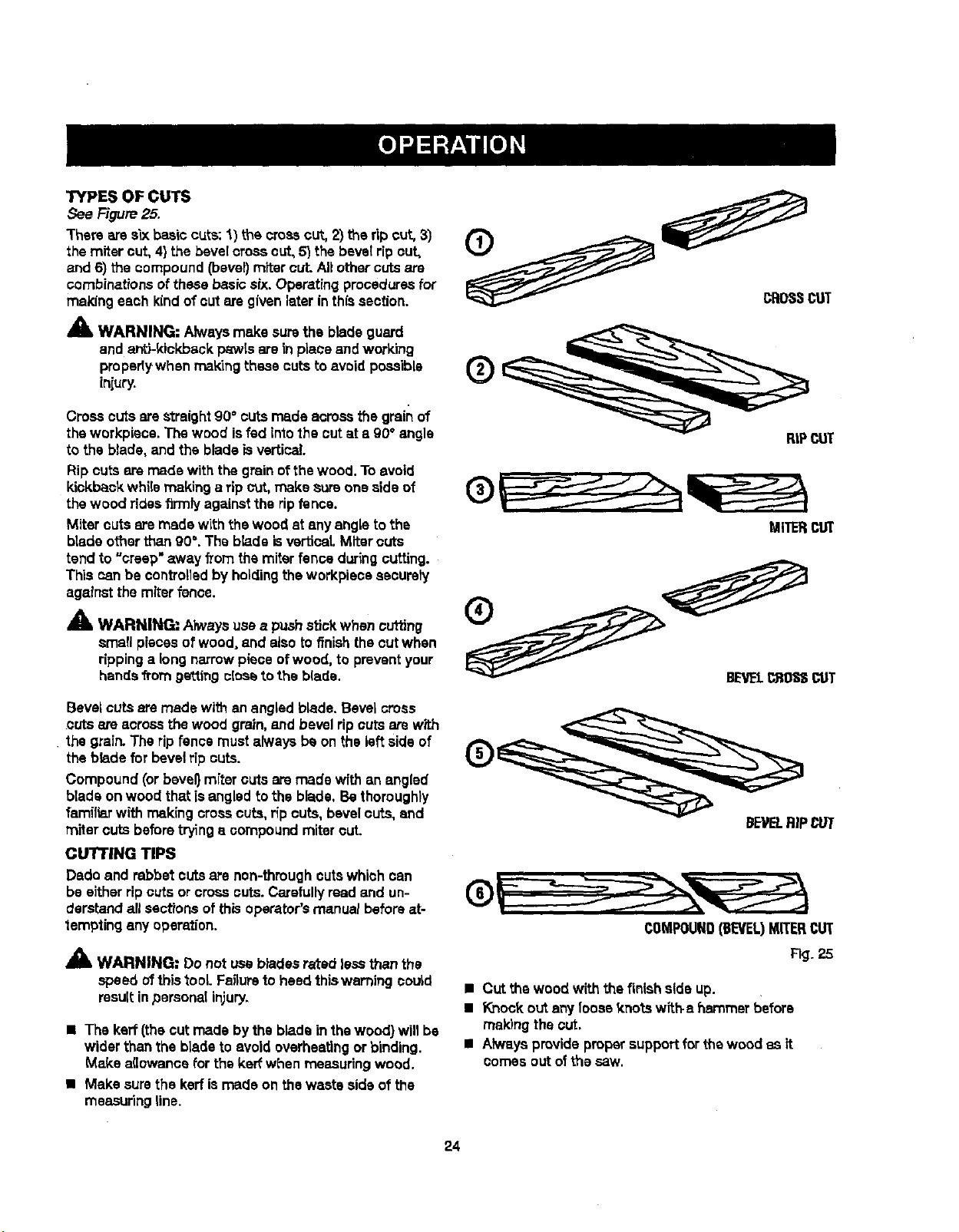
TYPES OF CUTS
See Figure25.
There aresixbas;ccuts:1) the crosscut, 2) the rip cut, 3)
the miter cut, 4}the bevelcross cut, 5) the beveldp cut,
and 6) the compound(bevel}mitercut. Altothercutsare
combinationsof thesebasic six,Operatingproceduresfor
making each kind of cutare givenlater inthissection.
_k WARNING: Alwaysmake surethe blade guard
and anti-kickback p_wIs are in place and work'rng
proparty when makingthese cutsto avoidpossible
iniury.
Crosscuts are straight90° cuts rr_ds acrossthe grain of
the workpiaos.The wood isfed into the outat a 90° angle
to the blade, and the blade isvertical.
Rip cuts are made withthe grain ofthewood. To avoid
kickbackwhilemaking a rip cut, make sure one side of
the wood ridesfirmly againstthe ripfence.
Miter cutsare madewith the wood at any angleto ths
blade otherthan 90°.The blade isverticaLMiter cuts
tend to "creep" away from the miterfence during cutting.
This can be controlledby holdingthe workplace astutely
againstthe miter fence.
_" WARNING; Always usea pushstickwhen cutting
small pieces of wood, and atsoto finishthe cutwhen
rippinga long narrowpiece ofwood, to preventyour
handsfrom ge'_t.ingo{ossto the blade.
Bevel cutsare made with anangled blade. Bevel cross
cuts are acrossthe wood grain,and bevelrip Gutsarewith
the grain.The rip fence mustalways be on the left sideof
the bladefor bevelrip cuts.
Compound (or bevel} miter cuts aremade with an angled
bladeon wood thatisangled to the blade, Be thoroughly
familiarwith making crosscuts, ripcuts, bevelcuts, and
miter cuts beforetryinga compound mitercuL
CUTTING TIPS
Dado and rabbet cutsare non-throughcutswhich can
be either ripoutsor cross cuts.Carefullyread and un-
derstandall sectionsofthis operator'smanual beforeat-
tempting any operation.
A WARNING= Do not usebtadasrated lessthan the
speed of thistool Fa_urato heed thiswarningcould
resultinpersonal in}ury,
• The kerr (thecut madeby the bladein thewood) willbe
wider than the bladeto avoidoverheatingor binding.
Make a(iowancefor the keff when measuringwood.
• Make surethe kerfismade on the waste side of the
measuring line.
RIPCUT
MITERCUT
COMPOUND(BEVEL)MITERCUT
Fig. 25
• Cut the wood with the finish side up.
• Knockout any looasknots witf_a hammer before
makingthe cut.
• AlwaysprovideproW supportfor the wood as it
comes out ofthe saw.
24
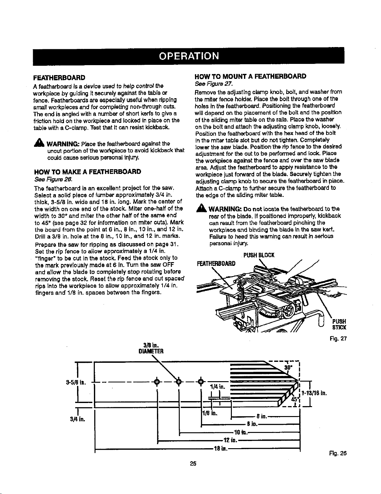
FEATHERBOARD
A fsatherboard is a device usedto heJpcontroithe
workpisce by guidingit securelyagainstthetable or
fence. Faatharboardsareespecially usefulwhen ripping
small workpiecesand for completingnon-throughcuts.
The end isangled with a numberofshort kerfsto givea
frictionhold on theworkplaceand lockedin place on the
table withe C-clamp, Testthatit can resistkickback.
A WARNING: Placethe featharboardagainstthe
uncutportionofthe wor_oieceto avoidkickback that
could cause seriouspersonaliniury.
HOW TO MAKE A FEATHERBOARD
See F/gum26.
The featherboard isan excellent project for the saw.
Select s solid piece of lumber approximately 3/4 in.
thick, 3-5/8 in.wide and 18 in. long. Mark the center of
the width on one end of the stock. Miter one-half of the
width to 30@and miter the other half of the same end
to 45° (see page 32 for information on miter cuts). Mark
the board from the point at 6 in., 8 in., 10 in., and 12 in.
Drilla 3/8 in. hoteat the 8 in., 10 in., and 12 in. marks.
Prepare the saw for ripping as discussed on page 31.
Set the rip fence to allow approximately a 1/4 in.
"finger" to be cut in the stock. Feed the stock onlyto
the mark previouslymade st 6 in. Turn the saw OFF
and allow the blade to completety stop rotating before
removing the stock. Reset the rip fence and cut spaced
ripsinto the workpisce 1o allow approximately 1/4 in.
fingers and 1/8 in. spaces between the fingers.
HOW TO MOUNT A FEATHERBOARD
See Figure27.
Removethe adjustingclamp knob, bolt,and washerfrom
the miter fence holder.Placethe boltthroughone ofthe
holesinthe featherboard. Positioningthe fsatherboard
willdepend on the placementoftheboltand the position
ofthe slidingmTtartable on the mils.Placethe washer
on the boltand attach the adiustingclamp knob, Ioosety.
Pos{tionthe featherboard with the hex headof the bolt
inthemitertableslotbutdo nottighten.Completely
lower the saw blade. Positionthe ripfence_othe desired
edjusb_ant for the cut to be performedand lock. Place
the workpiece againstthe fenceand over the saw blade
area. Adiust the featherbsard to applyresistanceto the
workplacejust forwardofthe blade. Securely tightenthe
adjustingclamp knobto securethefeatherboardin plane.
Attach a C-clamp tofurthersecurethefsatherboardto
the edge of the slidingmiter table.
_, WARN[NG" 0o not locate the featherboa_dto the
rearofthe blade. If positionedimproperly,kickback
canresultfromthe featherboard pinchingthe
workpiecaand binding the blade inthesaw kerr.
Failureto heed thiswarningcanresultinserious
personaliniury.
PUSHBLOCK
FEATHERBOARD
STICK
I
3-5/9in.
I
I
3/4in.
3/8in.
DIAMETER
\
- "-,--;o--,'
1OiL
12 is.
18in,
Fig.27
Fig. 26
25
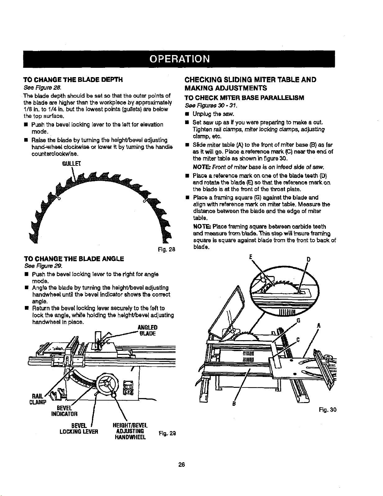
TOCHANGETHEBLADEDEPTH
See Rgure 28.
The blade depth shouldbe set so that the outerpointsof
the blade are higherthan theworkpisce by approximately
1/8 in.to 1/4 in. but the lowest points(gullets)are below
the top surface.
• Push the bevel locking[everto theleft forelevation
mode.
• Raisethe blade byturning the height/beveladjusting
hand-whe,s[ck>ck'wissor !ower it by turning the hendLs
oo_nterdo_k'w_se.
QULLL='(
Fig. 28
TO CHANGE THE BLADE ANGLE
See Figure29.
• Push the bevel [ocVdngleverto the rightfor angle
mode.
• Angle the bladeby turningthe height/beveladjusting
handwhealuntilthe bevel indicatorshowsthe correct
angle.
• Returnthe bevel lockingleversecurelyto the(eft to
lock theangle, whirsholdingthe height/beveladjusting
handwhealin piece.
AN_I.ED
CHECKING SLIDING MITER TABLE AND
MAKING ADJUSTMENTS
TO CHECK MITER BASE PARALLELISM
See Figures 30 - 31.
• Unplug the saw.
• Set saw up as if youwere preparing to make a out.
Tighten railclamps, miter lockingclamps,adjusting
clamp,etc.
• Slide miter table CA)to thefrontof miter base_) as far
as itwill go, Placea referencemark(C)nearthe end of
the miter _abteas shownin figure30.
NOT_ Frontofmiter base ison infeads'_e of saw.
• Place a referencemarkon one ofthe b_ds teeth (D)
and rotstathe blade (1_sothat thereferencemark on
the blade isat the frontofthe throatplate.
• Placea framingsquare(G)againstthe blade and
alignwith referencemark onmiter fable. Measure the
distancebetween the bladeend the edge ofmiter
table.
NOTE: Placeframingsquarebetween carbide teeth
and measure fro_ b_ade.Th_sstepw_ _nsurefTan_ng
squareissquareagainstbladefromthsfronttobackof
blade,
E 0
A
INDICATOR
BEVEL
LOCKINGIFVER
HEIgHT/BEVEL
ADJUSTING Fig,.2g
HANDWHEEL
Fig.30
26
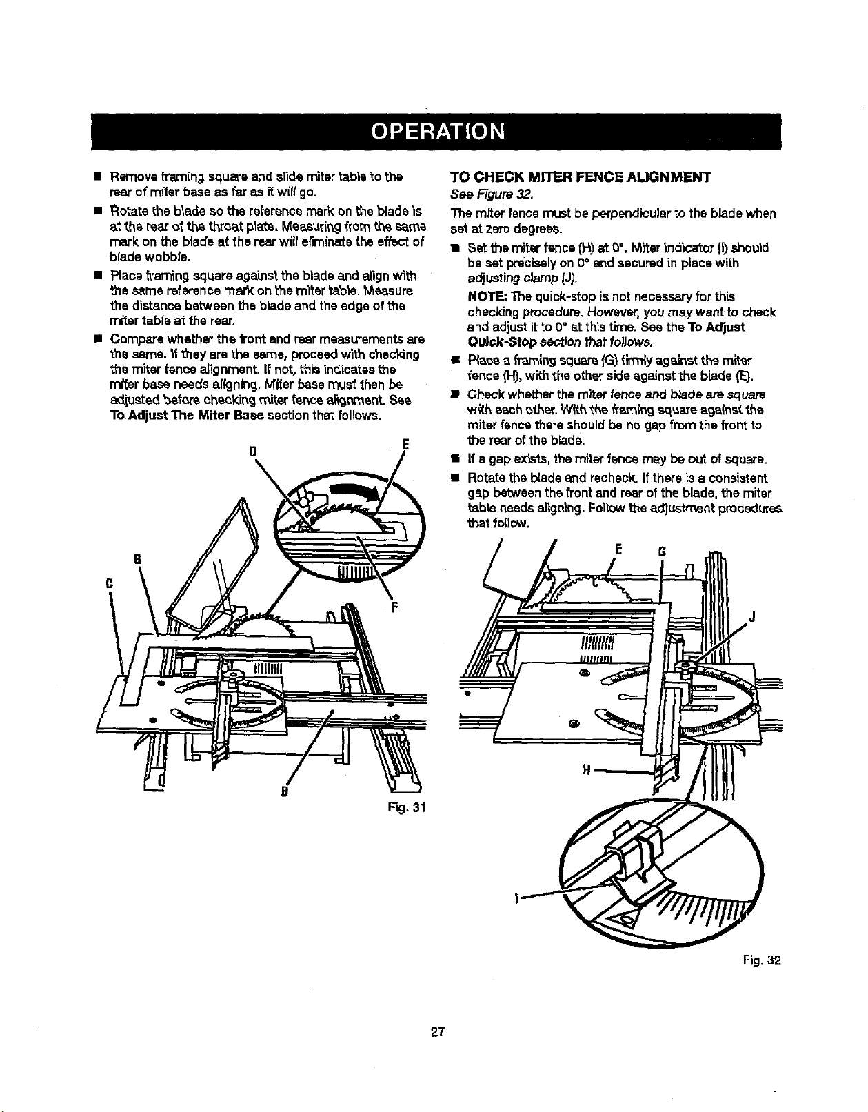
• Remove framinQ,squareand slide miter table to the
rear o1rafterbase as far as ftw(flgo.
• Rotate the bladeso the referencemarkon the bladeis
at the rearof the throat plate. Measuringfrom the s_ms
mark on the blade at the rearwiiferiminatsthe effect of
bladewobble.
• Place framing squareagainstthe bladeand alignwith
the same referencemarY:on the mitsrtable. Measure
the distancebetween theblade and the edge ofthe
miter table at the rear.
• Compare whether the frontand rearmeasurementsare
the same. It theyare the same, proceed with shecking
ths miter fence alignment, If not,this inc{icatasthe
miter base needs afign(ng. Mi!sr basemusl then be
adjustedbmforecheckingmiterfencealig_'nent.S_e
To Adjust The Miter Base sectionthat follows,
I] E
\
F
I
B
Fig. 31
3"0 CHECK MITER FENCE ALIGNMENT
See Figure32,
The miter fence mustbe perpendicularto the blade when
set at zerodegrees.
• Set _e miterfanes (H)at 0%M_er indicatoT (I)should
beset preciselyon 0° end securedin place with
adjustingclamp _J).
NOTE" The quick-atopisnot necessaryfor this
checkingprocedure.However,you may want.tocheck
and adjustit to 0° at this time. See the ToAdjust
Ou_k-Sl_> sent/on thaffo_ows.
• Plaeaa framingsqu_ {G) flnmiya_}_'_sttl_ miter
fence (H),withthe otherside against the blade (E}.
• Check whetherthe miterfenceand bladeate square
with each other. W#.hthe freLrn{n9 squmeage{net the
miterfence there shouldbe no gap fromthe front to
the rear ofthe blade,
• H a gap exists,themiterfence may beout ofsquare.
• Rotate thebladeand recheck.If there isa consistent
gap betweenthe front and rearof the blade, the miter
table needs a|ignlng.Followthe adjustment procedures
that follow.
Fig. 32
27
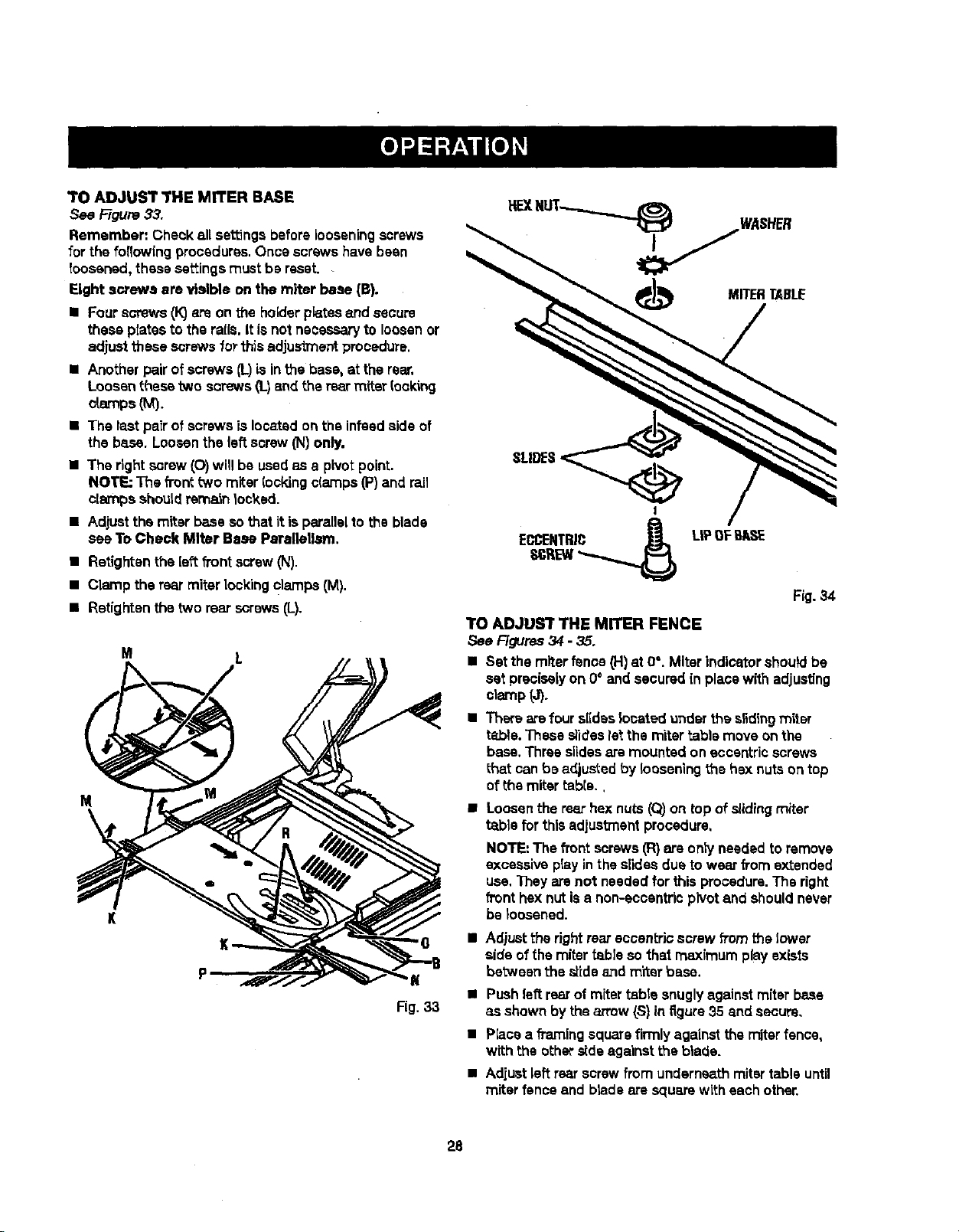
TO ADJUST THE MITER BASE
See Figure33.
Remember: Check all settingsbeforelooseningscrews
for the foflowfng procedures.Once screwshave bean
toosened, these settingsmust be reset.
Eight screws ere visible on the miter base (B).
• Four screws (k")o_eon the holderplates and secure
these platesto therails. It isnot necessaryto loosenor
adjustthese screwsforthis adjustment procedure.
• Anotherpairof screws (L)isin thebase, at the rear.
Loosen thesetwo screws(I-)end the rear miter (ocking
o[amps (M).
• The lastpaZrof screwsis located on the infesdside of
the base. Loosenthe leftscrew(N) only,
• The right screw (O)will be usedas a pivotpoint.
NOTE: The fTonttWOmiter locking c(amps(P)and rail
clarnps shouldrem_n locked.
• Adjustthe miter base so thatit isparallelto the blade
see To Check Miter Base Parsltellm'n.
• Retighten the [eftfi'ont screw(N).
• Clamp the rearmiter Lockingclamps (M).
• Retightenthe two rear screws(L).
M L
M
K
MITERTABLE
SLIDES
Fig. 34
TO ADJUST THE MITER FENCE
See F_Jras 34 - 35.
II Set the miter fence(H)at 0°. Miter indicatorshouldbe
set preciselyon 0° and securedin place with adjusting
cl_¢np(J).
• Ther_arefour slideslocated underthe s_dingmiter
ta,ble. These slideslet the miter table move onthe
base. Threeslidesare mounted on eccentricscrews
that can be adjustedby looseningthe hexnutson top
ofthe mitertable.,
• Loosenthe rearhex nuts (Q)on top of slidingmiter
table for thisadjustmentprocadure.
NOTE: The front screws(R)are ontyneededto remove
excessiveplay in the slidesdue to wear from extended
use. They are not neededfor this procedure.The right
fronthex nutisa non-eocantricpivotand shouldnever
be ;oasened.
• Adjustthe rightrear eccantrJcscrew fromthe lower
side ofthe miter table so that maximum play exists
betweenthes_ideand m'ftarbase.
K
• Pushleftrear ofmiter table snugly againstmiterbase
Fig.33 as shown by the arrow(S) in figure 35 and secure,
• P_ca a fi_'nlng squarefirmlyagainstthe miterfence,
with the other,rideagainstthe blade.
• Adjust left rear screwfrom undern_th mitertable until
miter fenceend brads are squarewith eachother,
28
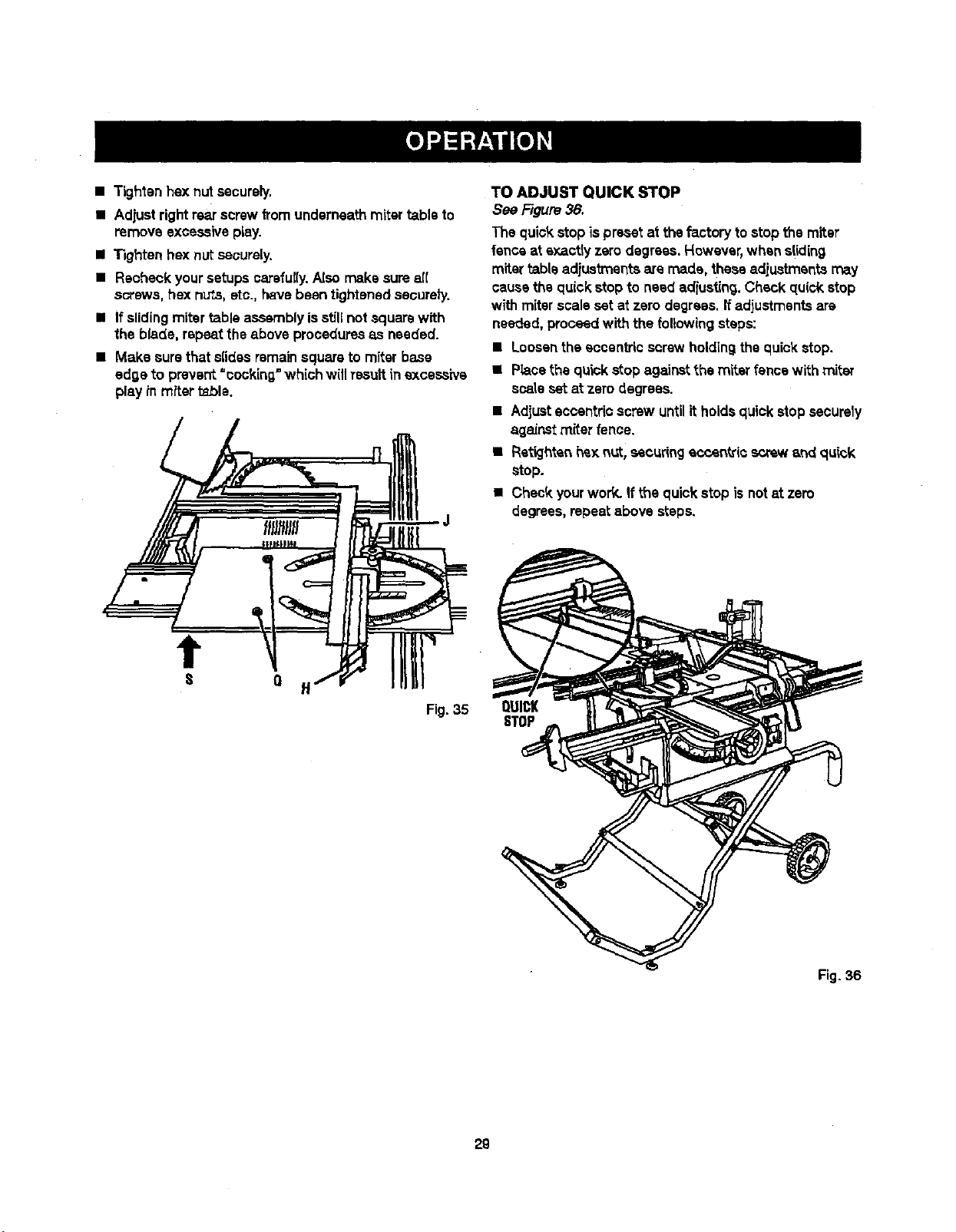
• Tightenhex nut securely.
• Adjust rightrear screwfromunderneathmitertable to
remove excessiveplay.
• Tighten hex nutsecurely.
• Recheckyoursetups carefully.Alse make surea[[
screws, hex nu_s,etc., h_vebeen tightenedsecurely.
• If slidingmitertable assemblyisstillnotsquare with
the blade, repeat the above proceduresas needed.
• Make surethat sfidss remainsquareto miter base
edo,eto preve_ =oookir=_=whichwillresultin excessive
play in miter table.
TO ADJUST QUICK STOP
See Figure38.
The quick stopis preset at thefactoryto stop the miter
fenceat sxactiy zerodegrees. However,when sliding
miter table adjustmentsare made, these adiustmentsmay
causethequickstop to need adiusting.Check qu(ck stop
withmiterscale set at zero degrees.Ifadjustmentsare
needed,proceedwith the followingsteps:
• Loosenthe eccentric screwholdingthequickstop.
• Piecethe quickstop againstthe miter fence with miter
scaleset at zero degrees.
• Adjusteccentricscrew untilit holdsquickstop securely
a_]aJnstmiter fence.
• Rstk..lhtenhe);nut, secur{ngeccentric screwand q,qck
stop.
• Check yourwork. If the quickstop isnotat zero
degrees,repeat above steps.
t
Q
Fig. 35
QUICK
STOP
Fig. 36
29
& WARNING: "1"oreduce ther_k of injury, always
make surethe ripfence isparalleltothe b_adebefore
b_innfng any opar_t'_o_.
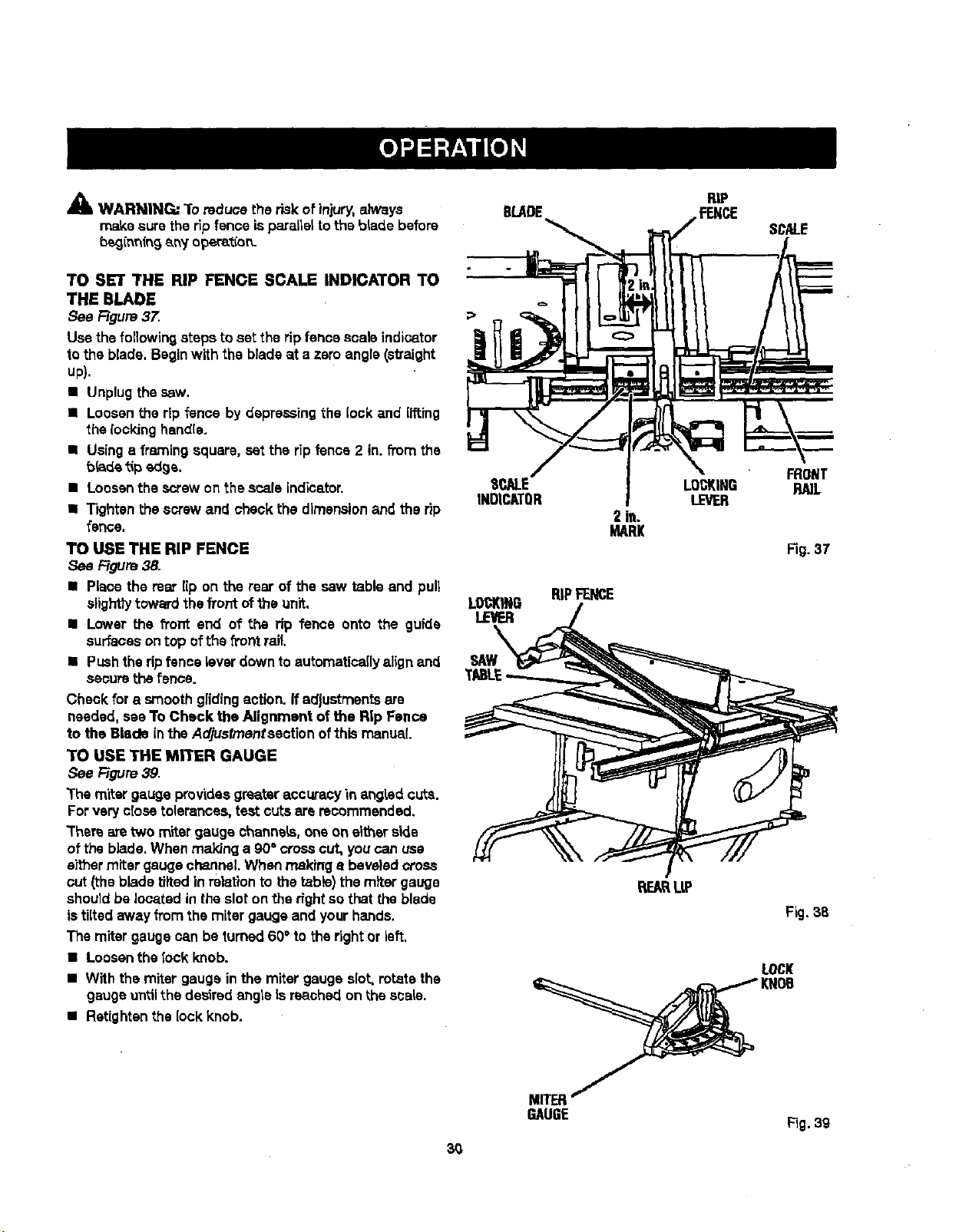
TO SET THE RIP FENCE SCALE INDICATOR TO
THE BLADE
See Figure37.
Use the following stepsto set the ripfence scale indicator
to the blade. Beginwith the blade at a zero angle(sVaight
up).
• Unplugthesaw.
• Loosen the ripfence by depressing the lock and lifting
the rooking handle.
• Using s framingsquare, set the rip fence 2 in. from the
bride tipedge.
• Loosenthe screw on the scale indicator.
• Tightenthe screw and checkthe dimensionand the rip
fence.
TO USE THE RIP FENCE
Figure38.
• Place the mar lip on the rear of the saw table and pull
slighttytoward thefront ofthe unit.
• Lower the front end of the rip fence onto the guide
surfacesontop ofthe front rail.
• Pushthe ripfence lever down to automaticaflyalign and
securethe fence.
Cheek fora smoothglidingaction. If adjustmentsare
needed, see To Check the Alignment of the Rip Fence
to the Blade in the Adjusfrnenfsectionofthis manual.
TO USE THE MITER GAUGE
See F=Jgure39.
The miter gauge providesgreateraccuracyin angHd cuts.
Forveryclose tolerances, test cutsare recommended.
Them aretwo miter gaugechannels,one on eitherside
of the blade.When maldng a 90° crosscut, you can use
either miter gauge channel.When makinga beveledcross
cut (thebladetilted in relationto the table)the miter gauge
sheutdbe locatedin the slot on the right so that the blade
istiltedaway from the miter gauge and yourhands.
The miter gauge can be turned60° to the rightor left.
• Loosenthe lock knob.
• With the miter gauge inthe miter gauge slot,rotate the
gaugeuntilthe desired angteisreached on the scale.
• Retightenthe lock knob.
BLADE
E
INDICATOR
2 in.
MARl(
LOCKING RiPFENCE
LEVER
SAW
RiP
FENCE SCALE
LOCKING RA]L
LEVER
Fig. 37
RE_ L|P
Fig.38
LOCK
MITER
GAUGE
Fig.39
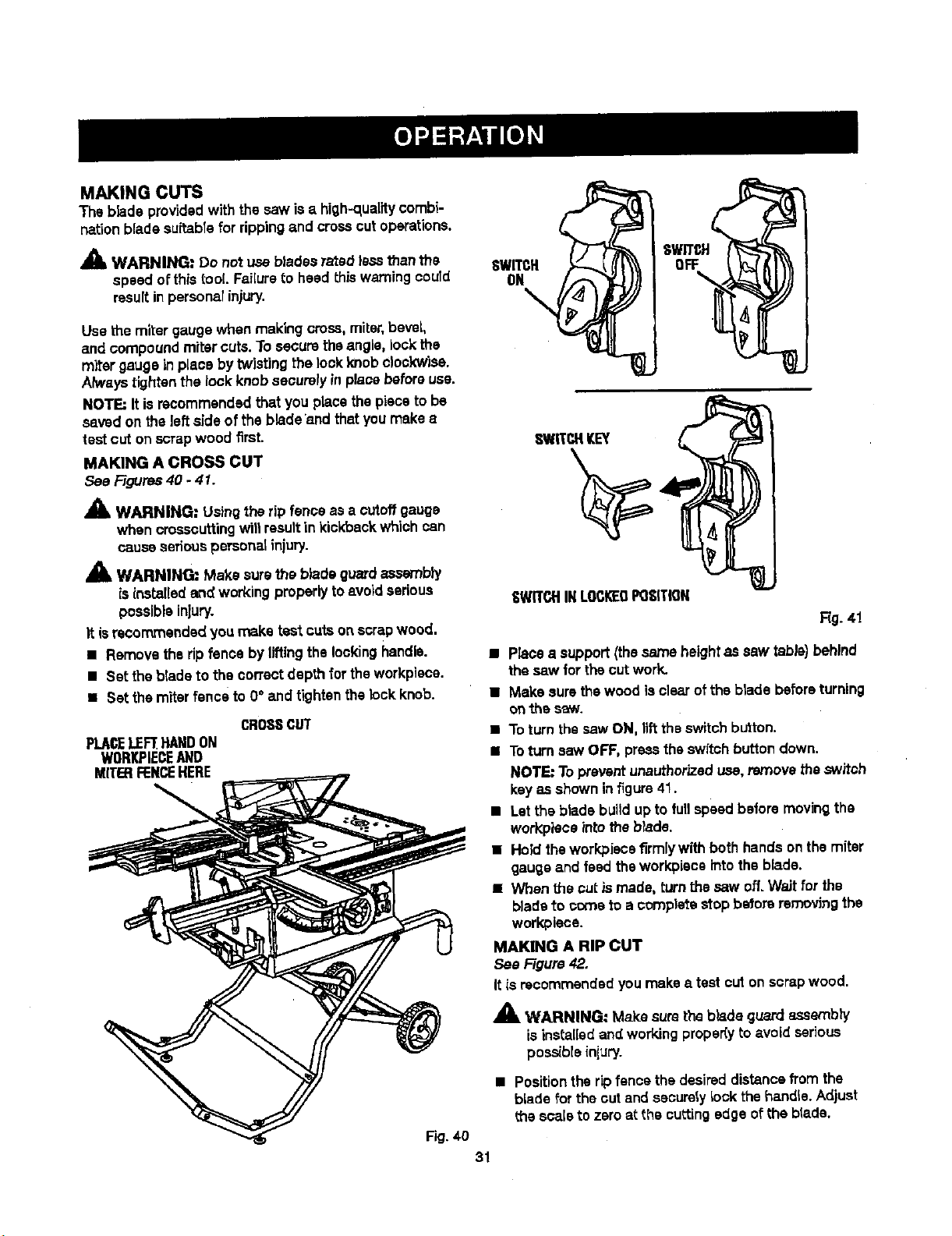
MAKINGCUTS
Thebladeprovidedwiththe saw is a high-quality combi-
nationbladesultabTefor ripping and crossout operations.
_1, WARNING: Do not use blades rated less thanthe
speed ofthis tool. FaiKureto heed this warningcould
resultin perscnalinjury.
Use themiter gaugewhen making cross, miter,bevel,
and compoundmiter cuts.To securethe angle, lock the
miter gaugein place by twisting the lockknobclockwise.
Always tightenthe lock knobsecurelyin pJaoebeforeuse.
NOTE=It isrecommendedthat you place the pieceto be
saved on theleftside of the bladeand thatyoumake a
test cut on scrapwood first.
MAKING A CROSS CUT
See Figures40 - 41.
WARNING: Usingthe rip fence as a cutoffgauge
when crosscuttingwit1resultin kickback whichcan
causeseriouspersonatinjury.
WARNING=: Make sure the bladeguardassembly
isinstalled and workingproperlytoavoidserious
possibleinjury.
It isrecommendedyou make test cutson scrapwood.
• Removethe ripfence by liftingthelockinghandle.
• Set the blade to the correctdepth for theworkpiece.
• Set themiter fence to 0°and tightenthe lockknob.
CROSSCUT
PLACELEFTHANDON
WORKPIECEAND
MITERFENCEHERE
Fig. 40
31
SWITCH
ON
\
SV//T_H
°?
SWITCHKEY
'8WITCHINLOCI_DPOSITION
Rg. 41
• Placea support(thesame height as saw table)behind
the saw for the cut work.
• Make sure thewood isclear ofthe blade beforeturning
onthe saw.
• To turn thesaw ON, liftthe switchbutton.
• Toturnsaw OFF, presstheswitch buttondown.
NOTE: Topreventunauthorizeduse,remove theswitch
keyas shownin figure41.
• Letthe bladebuildup to fullspeed before movingthe
wot_piece _ntotheb_ade.
• Hold the workpiecafirmlywith bothhandson the miter
gaugeand feed theworkpieceintothe blade.
• When the cut_ made, turn the saw off. Wait for the
bladeto cometo a completeHop betoreremoving the
workpiese.
MAKING A RiP CUT
See Figure42.
Itis recommendedyou make a test cuton scrapwood.
,_ WARNING: Make sure the blade guardassembly
isinstalledand workingproper(y to avoid serious
possibleinjLIry.
• Positiontherip fence the desired distancefrom the
blade for theout and sasurstylook the handle. Adjust
the scaleto zeroat the cuttingedge ofthe blade.
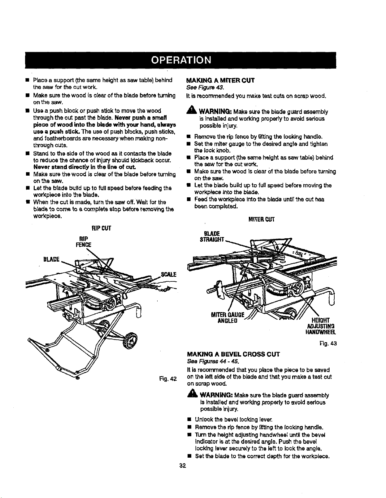
• P_aceasupport/,thesameheight as saw tablel behind
the.sawfor the cut work.
• Make sure the wood is clear of the blade before turning
on ti'_e ,_Lw.
• Use a pushblockor pushstick to movethewood
throughthe out past the bla_de.Never push a emafl
piece of wood into the blade with your hand, always
use a push stick. The useof pushblocks,pushsticks,
and feathathoards are necessarywhen ma_rngnon-
throughcuts.
• Stand tothe side of the wood as itcontacts the blade
to reduce thechance of injuryshouldkickback occur.
Never stand directly in the line of cut.
• Make sure thewood iss[earofthe blade beforeturning
onthe saw.
• Letthe blade b_Jildupto full speed beforefeeding the
workplece intotheblade.
• When the cut ismade, turnthe saw off.Wait for the
bladeto cometo a completestop before reme_ng the
wo_pieoe.
RiPCUT
RiP
FENCE
MAKING A MITER CUT
See F-agure43.
It isrecommendedyou rnsketest outs on scrap wood.
_k WARNING: Make sure the blade guard assembly
is installedand workingpmper]y to avoidserious
poes_is injury.
• Remove the ripfence by liftingthe lockinghandle.
• Set themiter gaugetothe desiredangle and tightsn
the lock knob.
• Placea support(thesame height as saw table) bah'rod
the saw forthe cutwork.
• Make surethewood is clear 0f the bladebeforeturning
on the saw.
• Letthe blade bugd up to fullspeed beforemoving the
work,piece intotheb_ade.
• Feed the work:pieceintothe blade untilthe outhas
been completed.
MITERCUT
BLADE
MITERGAUGE
ANGLED HEIGHT
AOJUSTING
HANDWHEB.
Fig.43
MAKING A BEVEL CROSS CUT
See Ffeures44 - 45.
Itis recommendedthatyou place the pieceto besaved
on the leftside of the bladeand thatyou make s test cut
on scrapwood.
X
WARNING: Make surethe blade guardassambly
isinstsJlsdand workingpmpedy to avoidserious
pose'lois_n)ury.
• Untookthe bevel Iocking 1ever.
• Removethe ripfence byliftingthe [o,_kinghandle.
• Turnthe heightadjustinghandwhesluntilthe bevel
indicatorisat the desiredangle. Pushthe beve(
lockingleversecurelyto the leftto lockthe angle.
• Set the bladeto the correctdepth for theworkpiece.
32
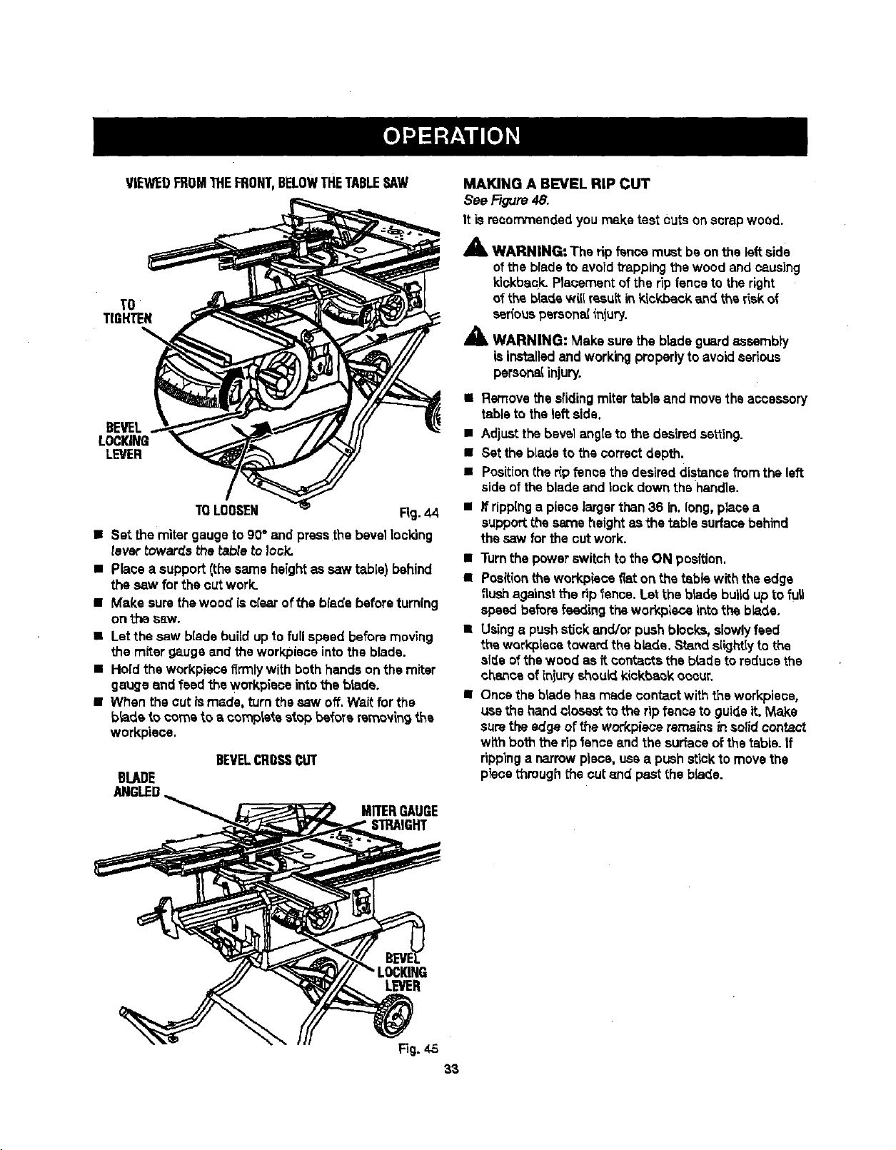
VIEWEDFROMTHEFRONT,BELOWTHETABLESAW
TO
TIGHTEN
BEVEL,
LOCKING
LEVER
TOLOOSEN Rg. 44
• Set themiter gaugeto g0° and pressthebevel Iocldng
tevartowards thetabteto Iosk.
• Place a support(the same heightas saw table) behind
the saw for the cut work.
• Make sure thewood isolaar ofthe blade beforeturning
onthe sew.
• Letthe saw bladebuildup to fullspeed beforemoving
the miter gaugeand theworkplace intothe blade.
• Hold the workplacefirmlywith bothhandson the miter
gaugeand feed the workpieoeintothe blade.
• When the cut _smade, turnthe saw off. Waitfor the
blade to cornsto a complatastop before rsmov_ngAs
workpisce.
BEVELCROSSCUT
BLADE
ANGLED
MITERGAUGE
STRAIGHT
MAKING A BEVEL RIP CUT
See Rgure 48.
It isrecommended you make test cutson scrapwood.
A
A WARNING: The rip f_ce must beon the left side
ofthe bladeto avoid_apping thewood and causing
kiokback.Plaoementofthe tip fenceto the right
of the blade will resultin k_ckbackarid the riskof
_fiouspersonalinjury.
_1_ WARNING: Make surethe blade guardassembly
isinstalledand workingproperlyto avoidserious
persona{injury.
• Removetheslidingmitertable and movethe accessory
tableto the left side.
• Adjustthe bevel angteto the desired setting.
• Set the blade to thecorrectdepth.
• Positionthe r_pfence the desireddistancefromthe left
sideof theblade and lock downthe handle.
• If rippinga piece largerthan36 in.long,place a
supportthe sameheight asthe _.ble surfacebehind
the saw forthe cut work.
• Turnthe power switchtothe ON position.
• Positiontheworkpisce fiaton the tabis with theedge
flush againsttheripfence. Letthe bisde buii_ up to full
speed before feeding the workplace intothe blade.
• Usinga pushstickand/orpush blocks, slowlyfeed
the workplacetoward the bb.de. Standslightlyto the
sl_e ofthe wood as it contactsthe bladetoreducethe
chance ofinjury shouldkickt_k occur.
• Once theblade hasmade contactwith the workplace,
usethe handclosesttothe rip fenceto guideit. Make
surethe edge ofthe workplaceremains insolidcontact
with boththe ripfenceand the surfaceof thetable. If
rippinga narrowpiece,usea pushstickto movethe
piece throughthe cutand pastthe blade.
LEVER
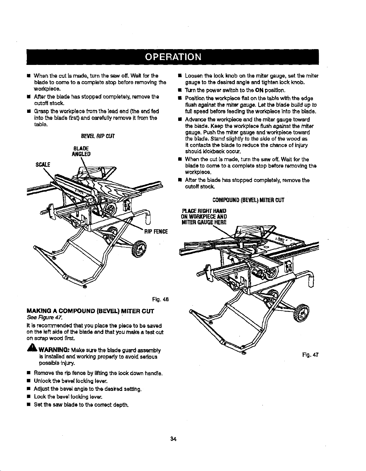
= When the outla made, turn the saw off.Wait forthe
bladeto come to a completestop before removingthe
workplace.
• After the bladehasstopped oomplateiy, removethe
cutoffstock.
• Grasp the workplece from the lead end (theand fed
into the b{adefirst) and carefullyremove itfrom the
table.
BEVEL.RiPCUT
8LADE
ANGLED
SCALE
\
• Loosenthe lock knobon the miter gauge, set the miter
gaugeto the desiredangleand tightenlock knob.
• Turnthe powerswitch to theON position.
• Positiontheworkpiece fiaton the tablewith the edge
flushagainstthe miter gauge. Let the blade buildup to
full speed before feedingtheworkplace Intothe blade.
• Advancetheworkplaceand themiter gaugetoward
the blade. Keep the workpieceflushagainst themiter
gauge. Pushthe miter gaugeand workplacetoward
the blade. Stand slightlytothe sideof the wood as
itcontactsthe blade to reduosthechance of injury
shouldkickback occur.
II Whenthe out Is made, turnthesaw off. Wait for the
blade to come to a completestop beforeremovingthe
workplace.
• Afterthe blade hasstopped completely,remove the
cutoffstock.
COMPOUND(BEVEL)MITERCUT
PL_ RIGHTHAND
ONWORKPIECEAND
MR'ERGAUGEHERE
Fig. 46
MAKING A COMPOUND (BEVEL) MITER CUT
See Figure47.
It is recommended thatyou place the piece to be saved
on the left side of the bladeand that you make a test cut
on scrapwood firsL
_1, WARNING: Make surethe blade guardass_"nbly
isinstalledand workingpropedyto avoid sadoue
posaiblainjury.
• Remove theripfence byliftingthe lock downhandle,
• Unlock:he bevel lockinglever.
• Adjustthe bevel angleto the desiredsetting.
• Lock the bevellocking lever.
• Set the saw blade to the correctdepth.
34
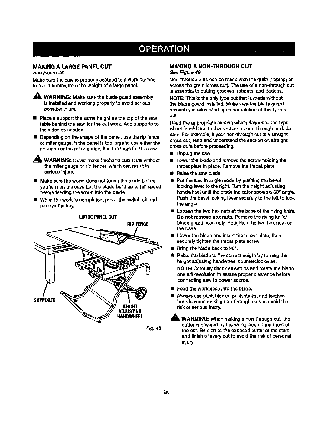
MAKING A LARGE PANEL CUT
See Figure48.
Make surethe sew is properlysecuredto e work surface
to avoidtippingfrom the weightof a large panel
_, WARNING: Make surethe b_adeguardassembly
isinstalledand workingproperlyto avoidserious
pessibteinjury.
• Placea supportthe same heightas the top of the saw
table behind the saw for the cutwork. Addsupportsto
the sidesas needed.
• Dependingon theshape of thepansl, usethe ripfence
or miteTgauge, ffthe panel istoo largeto uses_'herthe
rip{onceor the miter gauge, itistoo {argofor this saw.
_IL WARNING: Nsvsr make freehand cuts{cutswithout
the mitergaugeor ripfence),which canresultin
seriousinjury.
• Make sure thewood does not touchthe blade before
you turn on the saw, Let the blade bu_d up to fullspeed
beforefoeding the wood _,ntothe blade.
• When the work isoemplstod, pressthe switch offand
removethe key.
lARGEPN(ELCUT
RIPFENCE
HEIGHT
ADJUSTING
HANDWHEEL
Fig. _-8
MAKING A NON-THROUGH CUT
See Figure4g.
Non-throughcutscan be madewith the grain(ripping)or
acrossthe grain (crosscut}.The useofa nOn-throughcut
is essentialto cuttinggrooves,rabbets,and d,ad.oes.
NOTE: TtT_sis the onlytype outthat is madewithout
the blade guardinstsIled.Make surethe blade guard
assembly la reinstalleduponcompletion of thistype of
cut.
Read the appropriate sectionwhichdescribesthe type
of cut inaddition to this section on non-throughor dado
cuts. Forexample,if yournon-throughcut is a straight
cross cut, read and understandthe sectionon straight
cross cuts before procaed{ng.
• Unplug the saw.
• Lowerthe blade and removethe screwholdingthe
throat plate in place.Removethe throatplate.
• RaLsethe saw blade.
• Put the sew inanglemode by pushingthe bevel
lockinglavarto theright.Turnthe heightadjusting
hsndwheeluntil the b(adeindicstershowsa 30" ar_jis.
Push thebevel locking{eversecurelyto the[eftto lock
the angle,
• Loosenthe two hexnutsst the baseof the rivingknife.
Do not remove hex nuts. Removethe rivingknife/
blade guard assembly.Retightanthetwo hex nuts on
the base,
• Lowerthe blade and insert thethroat plate,then
securelytighten thethroatplate screw.
• Bring the blade backto gO°.
• Raise the blade_othe correcthaigh'tby tuTningthe
height ad{ustinghandwheelcounterclockwise.
NOTE: Carefullycheckall setupsand rctsta the blade
one fur{revolutionto assureproperclearancebefore
connecting saw topowersource.
• Feed theworkpiscs into the blade.
• Always use pushblocks, pushsticks,and feather-
boards when makingnon-throughcutstoavoidthe
risk of seriousinjury,
_1= WARNING: When makinga non-through cut, the
cutter iscoveredbythe warY,piece duringmost ot
the cut. Be alert to the exposedcutter at the start
and finishof everycut to avoid the risk of personal
injury.
35
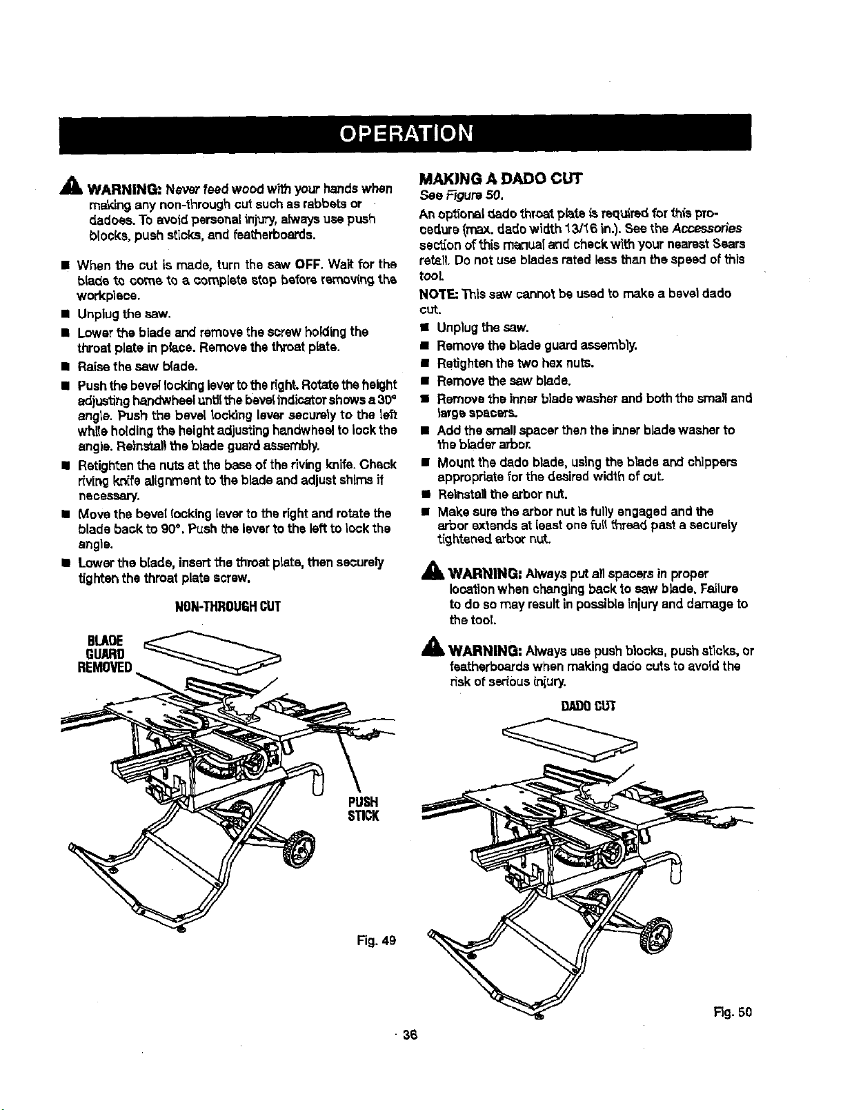
,_ WARNING: Never feed wood with yourhandswhen
ma_dngany non-throughcut suchas rabbets or
dadoes. To avoidpersonalinjury, aJways usepush
blocks, push sticks,and featherboards.
• When the cut is made, turn the saw OFF. Wait for the
blade to come to a complete stop before removingthe
workpieca.
• Unplugthe saw.
• Lowerthe blade and removethe screwholding the
throat plate in place. Remove thethroatplate.
• Raise thesaw b(ade.
• Push thebeveilockingleveeto theright.Rotatetheheight
adjustinghandwheelunUithebevelindicatorshowsa 30+
angle. Push the bevel Iocldng leveesecurelyto the left
whileholdingthe heightadjustinghandwheelto lockthe
angle. Reinsta_the b_adeguardassembly.
• Retightenthe nuts at the base oftherivingknife.Check
rivingkni_'ealignmentto theblade and adjustshimsif
necessary.
• Move the bevel locking[everto therightand rotatethe
blade back to 90%Push the leverto the left to lock the
angle.
• Lowerthe blade, insertthe throat plate,then securely
tighten the throatplate screw.
NON-THROUGHCUT
BLADE
GUARD
REMOVED
MAKING A DADO CUT
See _gurs 50.
An optior_l _Ladothroat plate _sreq_drsdfor this pro-
cadurs (max. dadowirtth_3/16 in.). See the Accessorles
sectionof this manua! and checkwith yournearestSears
retsil.Do not usebladesrated lessthan thespeed of this
tooL
NOTE: Thissaw cannotbeused tomake a bevel dado
CUt.
• Unplugthe saw.
• Remove the bladeguard aseembly.
• Ratlghtanthe two hexnuts.
• Remove thesaw blade.
• Remove_heinnerblade washer and boththe sma_and
_eegespacers.
• Add the smellspacer thenthe innerb]adewasher to
the bladesarbor.
• Mount the dado blade, usingthe blade and chippers
appropriatefor the desired width of cut.
• Reinstallthe arbor nut.
• Make sure thearbor nut Isfullyengaged and the
eebor extends at loast one fiJll_rsad past a sacurely
tightened arbornut.
_k WARNING; Alwaysput all spacersin proper
locationwhen changingback to saw blade. Failure
to do somay resultinpossibleinjuryand damage to
the tool.
A WARNING: Akvays usepushblocks, pushstlc_, or
fsatharbcardswhen makingdado cutstoavoidthe
risk of seriousinjury.
9J_l}0CUT
PUSH
STICK
Fig.4g
• 36
F_g.50
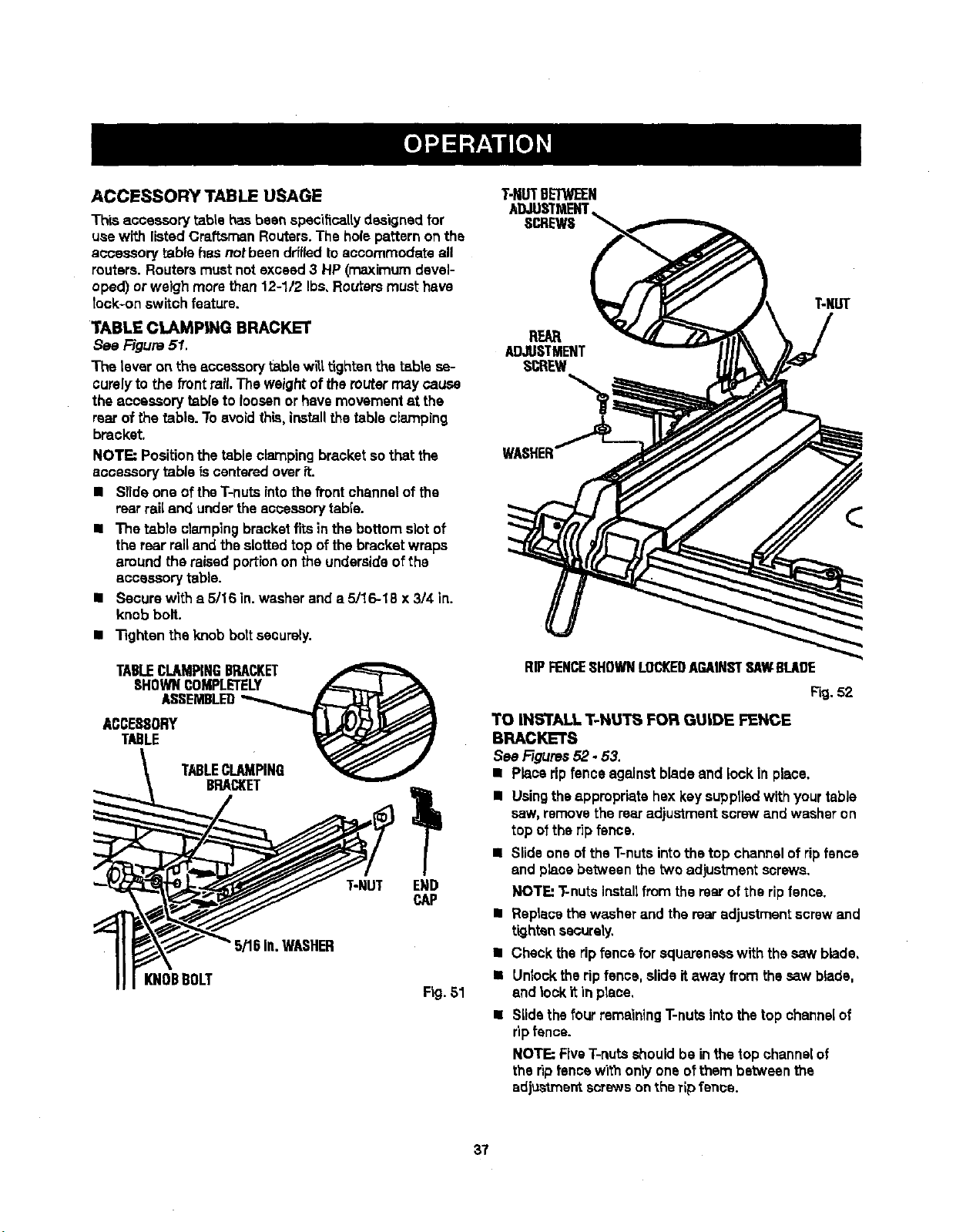
ACCESSORY TABLE USAGE
Th|saccessory table hasbeen spec'dtcaltydesignedfor
usewith listedCraftsmenRoutars.The holepatternon the
accessory table hasnotbeen drffladtoaccommodateall
reuters. Reutersmust notexceed 3 HP (maximumdevel-
oped) or weigh morethan 12-1/2 Ibs.Reutersmust have
took-onswitch feature.
TABLE CLAMP|NG BRACKET
See Figure 51.
The lever on the accessory table wilt.tighten the table se-
curelyto the front rail.The weightofthe muter may cause
the accessory table to loosenorhavemovementst the
rearof the table. Toavoidthis, installthetable clamping
bracket.
NOTE: Positionthe table clampingbracket sothat the
accessorytable iscenteredover it.
II Slide one oftheT-nutsintothefrontchannelof the
rearrail and underthe aooeseorytable.
• The table clamping bracketfitsin the bottomslot of
the rear railand the slottedtop ofthe bracketwraps
aroundthe raisedportion on the undersideofthe
accessorytable.
• Secure wlth a 5/16 in.washer and a 5/16-18 x 3/4 in.
knob bolt.
• Tighten the knobbolt securely.
TABLECLAMPINGBRACKET
SHOWNCOMPLETELY _
ASSEMBLED__,._
ACCESSORY L L_L)_
T.,E
TABLECLAMPING
BRACKET
T-NUT
_/'16in.WASHER
KNOBBOLT
END
CAP
Fig. 51
T-NUTBETWEEN
ADJUSTMENT
SCREWS
REAR
ADJUSTMENT
SCREW
RIPFENCESHOWNLOCKEDAGAINSTSAWBLADE
Fig, 52
TO INSTALL T-NU'£_ FOR GUIDE FENCE
BRACKETS
See Figures52.53.
• Placeripfence againstblade and lock in place,
• Usingthe appropriatehex key suppliedwithyourtable
saw,remove the rearadjustmentscrewand washeron
top of the rip fence.
• Slideone ofthe T-nutsintothe top channelof ripfence
and placebetween the two adjustmentscrews.
NOTE: T-nutsinstallfrom the rearof the ripfence.
• Replacethewasher and the rearadjustmentscrewand
tighten securely.
• Checkthe ripfsncs for squarsnesswith ths saw blade,
• Unlocktheripfence, slideitaway from thesaw blade,
and lockit in place,
Slidethe fourremainingT-nutsintothetop channelof
ripfence.
NOTE:FiveT-nutsshouldbe inthe top channelof
the ripfencewith onlyone ofthem between the
adjustmentscrewson therip fence.
37
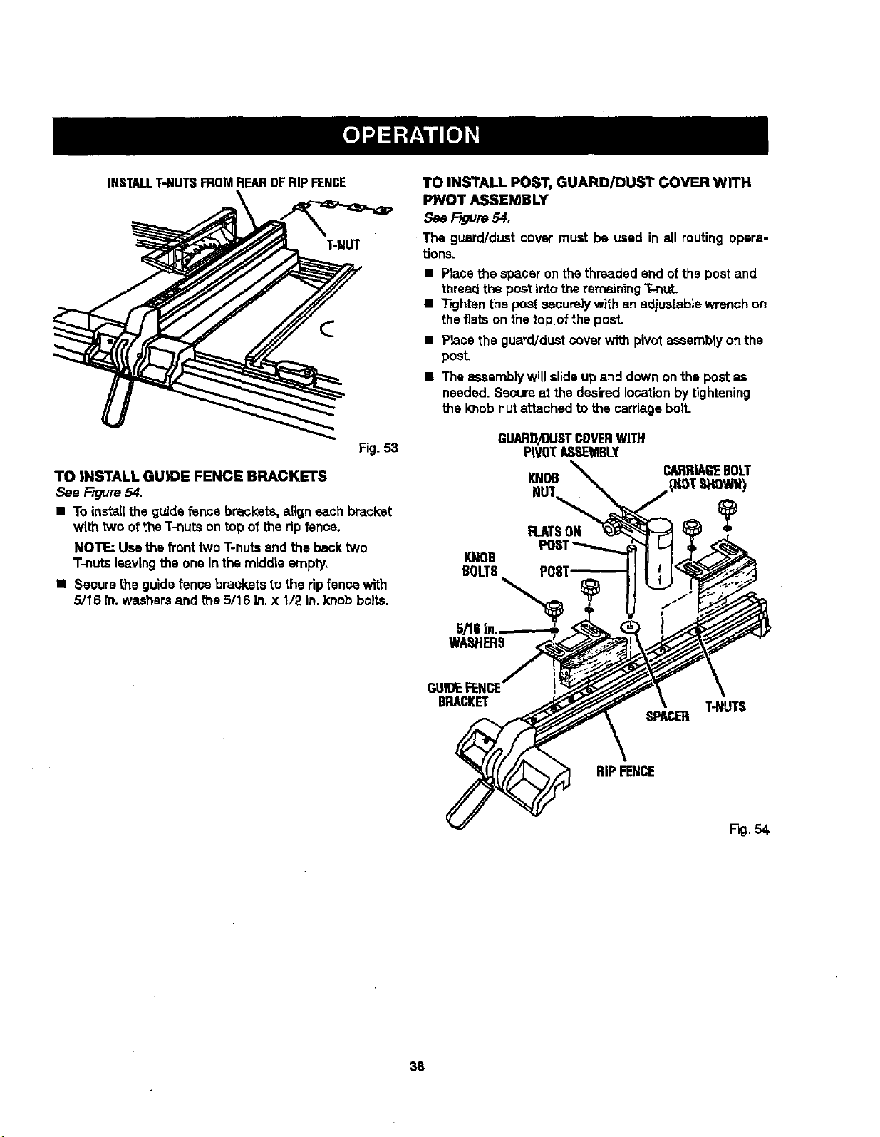
INSTALLT-NUTSFROMREAROFRIPFENCE
T-NUT
Fig.53
TOINSTALLGUIDEFENCEBRACKETS
See F/gum 54.
• To install the guidefence brackets, align each bracket
with two ofthe T-nutson top of the ripfence.
NOTE=Usathe hnt twoT-nutsand the backtwo
T-nutsleavingthe one inthe middle empty.
• Securethe guide fence brackets to the rip fence with
5/16 in. washersand the5/16 in.x 1/2 in.knob bolts.
TO INSTALL POST, GUARD/DUST COVER WITH
PIVOT ASSEMBLY
See F/gum54.
The guard/dust cover must be used in all routing opera-
tions.
• Placethe spaceron the threaded end ofthe post and
threadthe post intotheremaining"i-nut.
• Tightsnthe postsecurelywith an ad.iustab|ewrenchon
the fiatson the top of the post.
• Planethe guard/dustcoverwith pivotassemblyon the
pesL
• "Theassemblywillslideup and downon the post as
needed. Scoursat the desired location by tightening
the knobnut attached to the carriagebolt.
GUARD)DUSTCOVERWITH
P|VO_ASEMBLY
KNOB
FLAT8ON
KNOB
BOLTS
5/tll i.
WASHERS
CARRIAGEBOLT
GUIDE FENCE
BRACKET
T-NUTS
SPACER
RIPFENCE
Fig. 54.
38
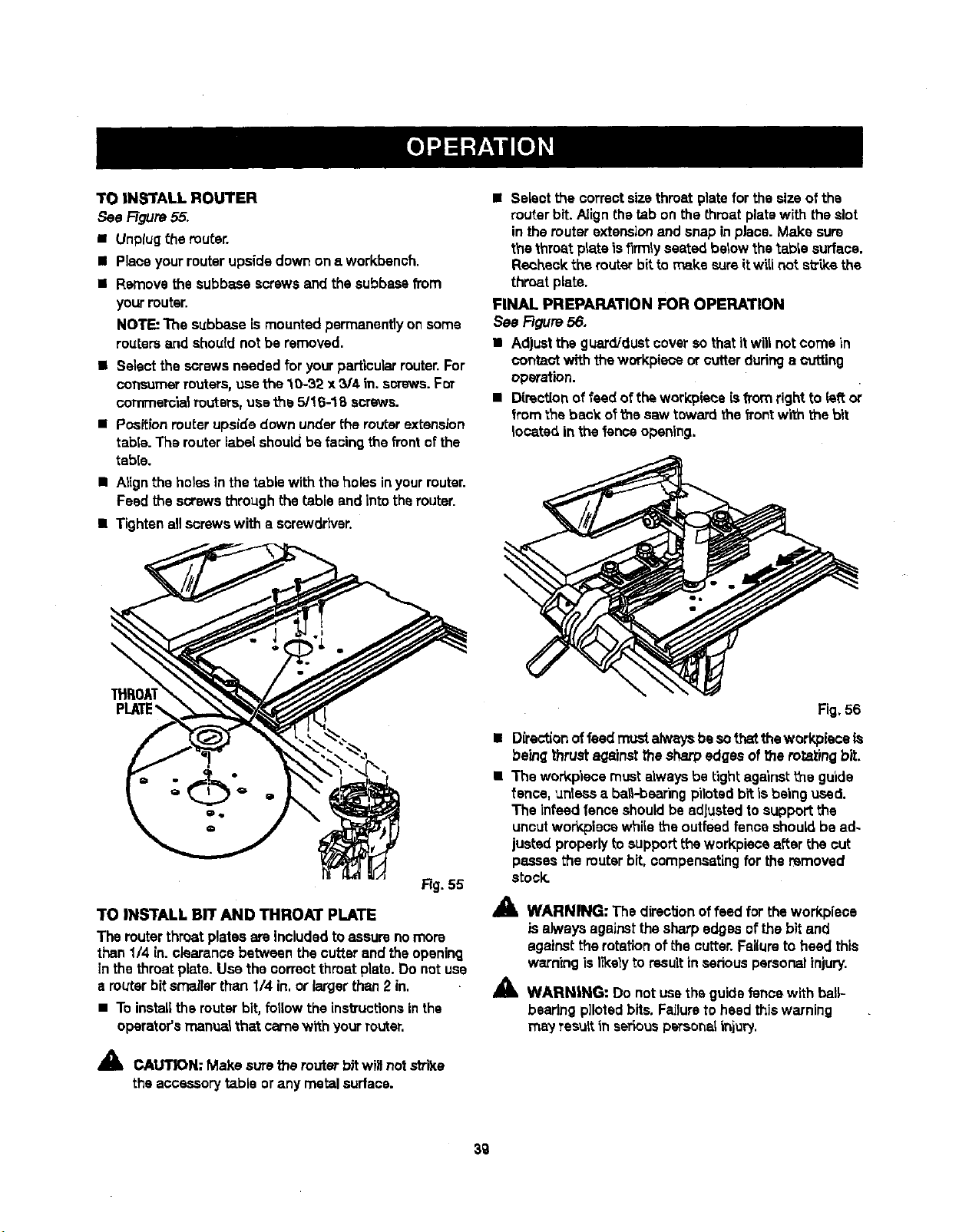
TOINSTALLROUTER
See Ftgure55.
• Unptugthe router.
• Placeyourrouter upsidedown ona workbench.
• Remove thesubbase screwsand thesubbasefrom
yourrouter.
NOTE: The subbase ismounted permanentlyonsome
routereand shouldnot be removed.
• Selectthescrewsneeded for yourparticularrouter.For
consumerreuters, usethe10-32 x 3/4 in. screws.For
eommerc'la_Pouters,usethe 5/16-18 screws.
• Positionrouterupside down underthe routerextension
tabie. The routerlabelshouldbe facingthe front ofthe
table.
• Atignthe holesin the tablewith the holes inyourrouter.
Feed the screwsthroughthe table and intothe router.
• Tightenallscrewswith a screwdriver.
• Selectthe correctsizethroat platefor the sizeof the
routerbit.Alignthetab on the throat platewith theslot
in themuter extension and snap inplace. Make sure
thethroat plateis firmly seated belowthe_able surface.
Recheck the router bit to make sureitwillnot s_ke the
throat plate.
FINAL PREPARATION FOR OPERATION
See Figure56.
• Adjustthe guard/dustcover sothat itwillnotcorns in
conta_ with theworkplaceor cutter duringa cutting
operation.
• D[rectionof feed oftheworkplace isfromright to leftor
from theback oft'nesaw toward the frontwith the bit
located inthe fenceopening.
\
i
Rg. 55
TO INSTALL BIT AND THROAT PLATE
The routerthroat plates areincludedtoassure nomore
than1/4 in.eisarancebetween thecutter and the opening
in the throat plate. Use the correct throat plate.Do not use
a routerbitsmallerthan I/4 in,or largerthan2 in.
• To installthe routerbit,fotlow the instructionsinthe
operator'smanua_that camewith yourrouter.
_" CAIN: Make sure the router bitwillnot strike
theaccessory table orany metal surface.
Fig.56
• Directionoffeedmustalw,_ysbesothattheworkpieceis
beingthrust againstthesharpedges of the foraying bit.
• The workp'lecemust alwaysbe tight against_e guide
fence, unlessa ba_-bearing pilotedbit is being used.
The Infeed fenceshouldbe adjustedto supportthe
uncutworkpiees whi_ethe outfeedfence shouldbe ad-
justed properlyto supportthe workpisce afterthe cut
passesthe routerbit, compensatingfor the removed
stock.
41_ WARNING: The directionoffeed for theworkpiece
isalwaysagainstthe sharpedges ofthe bit and
againstthe rotationof the cutter.Fai(uroto heed this
warningisI_ely to resultin sedous personalinjury.
_i, WARNING: Do notuse the guidefencewith ball--
bearingpilotedbits. Failureto heed thiswarning
may TesuRin seriouspeTsonalinjury.
3g
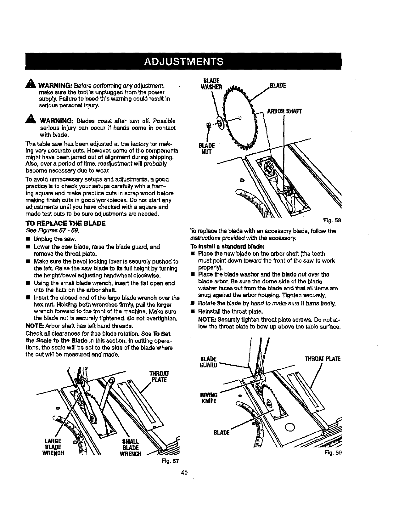
A WARNING." Before performing anyadjustment,
make sure the tool is unpluggedfrom the power
suppty.Failureto heed thiswaTn'lngcoutdresu)tin
seriouspersona_injury.
A WARNING: Blades coast after turn off. Possib}e
serious injury can occur if hands come in contact
with blade.
The table sew has been adjusted at the factoryfor mak-
ingveryaccurate cuts. However,some ofthe components
mighthavebeen jarred out of alignmentduringshipping.
ALso,overa period oft'rne,rsediustmentwillprobably
become necessary due towear.
3"0avoidunnecessary setups and adjustmen*.s,a good
practiceisto check yoursetupscarefullywith a fram-
ingsquareand make practicecutsin scrapwood before
making finishcuts in goodworkpiaces.Do not start any
adjustments untilyou havechecked with a squareand
made test cuts to be sure adjustments are needed.
TO REPLACE THE BLADE
See Figures57 - 59.
• Unplugthe saw.
• Lowerthe saw blade, raisetheblade guard,and
remove the throet plate.
• Make surethe bevel lockingleverissecurelypushed to
the felt. Raise the sew bladeto itsfull heightbyturning
the haight/beve_ adjusting handwheelclockwise.
• Usingthe smallblade wrench, inserttheflat open and
intothe fiats on the arbor shaft.
• Insertthe closed and of the largebladewrench overthe
hax nut. Holdingbo_.hwrenches li_nly, pull_.h_larger
wrenchforward to the f1"ontof the machine.Make sure
the blade nut is securelytightened. De not overtighten.
NOTE: Arborshaft hasleft handthreads.
Check allcrearancesfor freebladerotation.See ToSet
the Scale to the Blade in thissection.In cutting opera-
tions,the scarewilt be set to the side ofthe bladewhere
the cut will be measuredand made.
THROM
PLATE
BLADE
NUT
Fig. 58
To replacethe bladewith an accessoryblade, followthe
instructionsprov'_ed with theaccessory.
To Inatall e standard blade:
• Placethenew blade onthe arbor shaft(theteeth
mustpointdown towardthe fi'ontof thesaw towork
properly),
• Placethe bladewasher and the bladenut over the
bladearbor.Be surethe dome side of the blade
washer f_cas ou_.from _a bladeand that all items ere
snugagainst thearbor housing,13ghtensecurely.
• Rotate the bladeby handto make sure it turnsfreely.
• Reinstallthethroat plate.
NOTE: Seaurelytightenthroat plate screws. Do notal-
low thethroatplate to bow up above the table surface.
BLADE THROATPLATE
RMNG
KNIFE
LARGE SMALL
BLADE BLADE
WRENCH WRENCH
Fig.57
40
BLAI)E
©
Fig. 59
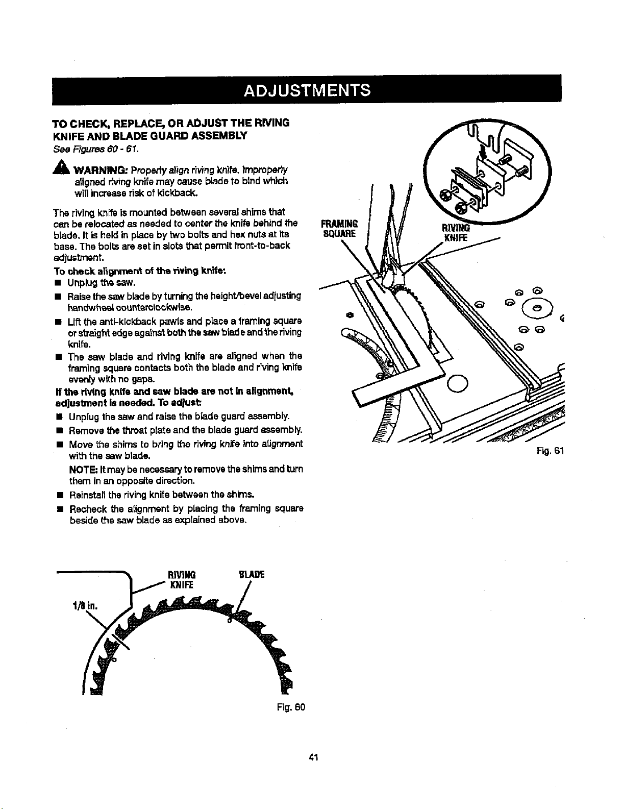
TOCHECK,REPLACE,ORADJUSTTHERIVING
KNIFEANDBLADEGUARDASSEMBLY
See Figures60 - 61.
A
AlL WARNING: Propertyalignriving knits.|mproperiy
atignedrivingknifemay cause bladeto btndwhich
willincreaserisk ofkickback.
The rivingknifeis mounted betweenseveral shims that
can be relocatedas neededto center the knife behindthe
blade. Itis heldin place by two boltsand hex nutsat its
base. The boltsareset inslots that permitfront-to-back
adjusb'nent.
"Tocheck a_gnment of the _vin 9 knife:
• Unplugthe saw.
• Raisethesaw bladebyturningtheheight/beveladiuating
har_twheel¢ountsml_ckwisa.
• Liftthe anti-kickback pawlsand place a framingsquare
ors'_mightedge againstboththe saw bladeandthe riving
knife.
• The saw blade and riving knife are aligned when the
framing squarecontacts boththe biade and rh/ingknife
eventywith no gaps.
If the dvthg knife and saw blade am not In alignment,
adjustment is needed. To adjust:.
• Unplug thesaw and raisethe b_adeguard assambly.
• Remove thethroat plateand the bladeguardassembly.
• Move the shimsto bringthe rivingknife into alignment
with the saw blade.
NOTE"Itmaybenecessarytoremovetheshimsandturn
them in an oppositedirection.
• Ralnstafltherivingknifebetween the shims.
• Recheck the atignmentby placing the framing square
beside the saw blade as explainedabove.
FRAMING
SQUARE
Fig. 61
1/8in.
RIVING BLADE
KNIFE
R_. 60
41
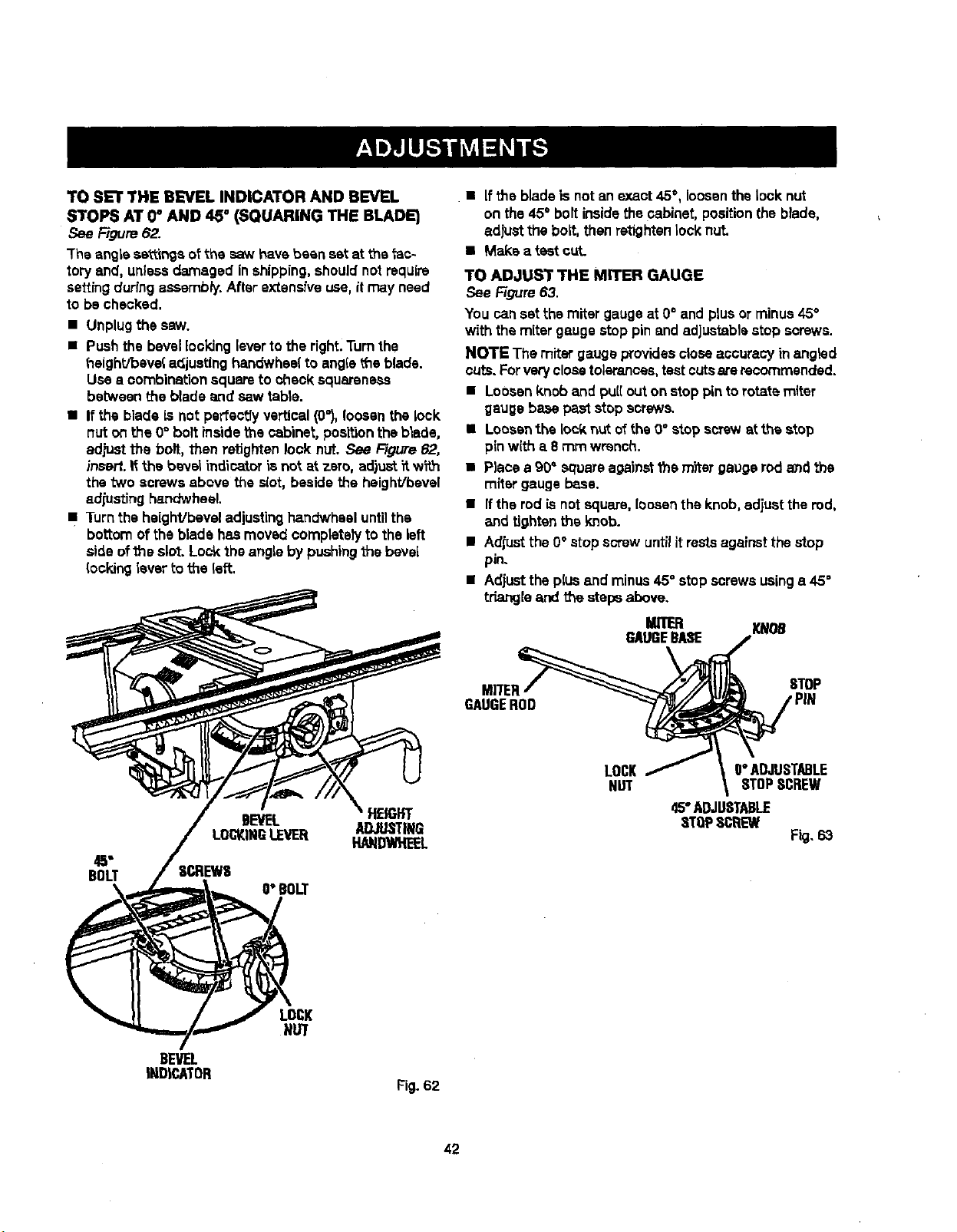
TO SET THE B_VEL INDICATOR AND BEVEL
STOPS AT 0_ AND 45 ° (SQUARING THE BLADE)
Figure62.
The angle sa_mgs oFthe saw havebeen set at the _ac-
tory and, unlessdamaged inshipping,shouldnot require
settingduringassembly. After extensive use, itmay need
to be checked.
• Unplugthe saw.
• Pushthe bevellooking leverto the right.Turnthe
t_eight/beve{ adjustinghandwhsel to angleL'heblade.
Use • combinationsquareto check squareness
between theblade and saw table.
• If the blade is not perfectlyvertical(0_),loosenthe lock
nut on the 0° bolt _nsidethe cabinet, positionthe blade,
adjustthe bolt, then retightenlock nut. See Figure62,
insall, if the banal indicatoris not at zero, adjust_tw_.h
the "twoscrews above the slot, besidethe heighVbevel
adjusting handwheel.
• Turn theheighVbeveladjustingha.ndwhesluntilthe
bottom of the blade has moved completelyto theleft
side ofthe slot. Lock the angleby pushing the bevel
_ockinglever to the left.
BOLT
BEVEL HEIGHT
ADJUSTING
LOCKINGLEVEE[ HANDWHEEL
O"BOLT
BEVEL
INDICATOR
LOCK
NUT
Fig. 62
• Ifthe bladeis not anexact 45°, loosenthe lock nut
on the 45° boltinsidethecabinet, positionthe blade,
adjustthe bolt, then retighten lock nut.
• Make a test cut.
TO ADJUST THE MITER GAUGE
See Figure63.
You can setthe miter gaugeat O° and plusor minus45°
with the mitergaugestop pin andadjustablestop screws.
NOTE The miter gaugeprovidescloseaccuracy inangled
cuts.Forveryclosetolerances,testcutsarerecommended.
• Loosenknoband pull out on stoppin torotate miter
gaugebasepaststop screws.
• Loosenthe lockn_t ofthe 0° stop screwst the stop
pinwith a 8 rnmwrench.
• Place a 90" squareagainstthe m_ar gaugerodand the
miter gauge base.
• Ifthe rod isnotsquare, loosenthe knob, adjustthe rod,
and tightenthe knob.
• Adjustthe 0°atop screw untilitrestsagainstthe stop
pin.
• Adjustthe plusend minus 45° stop screwsusinga 45°
triangle and the stepsabove.
MITER
GAUGEBASE
MITER_
GAUGEROD
LOCK/
NUT
m
O"ADJUSTABLE
STOPSCREW
45"ADJUSTABLE
STOPSCREW
Fig. 63
42
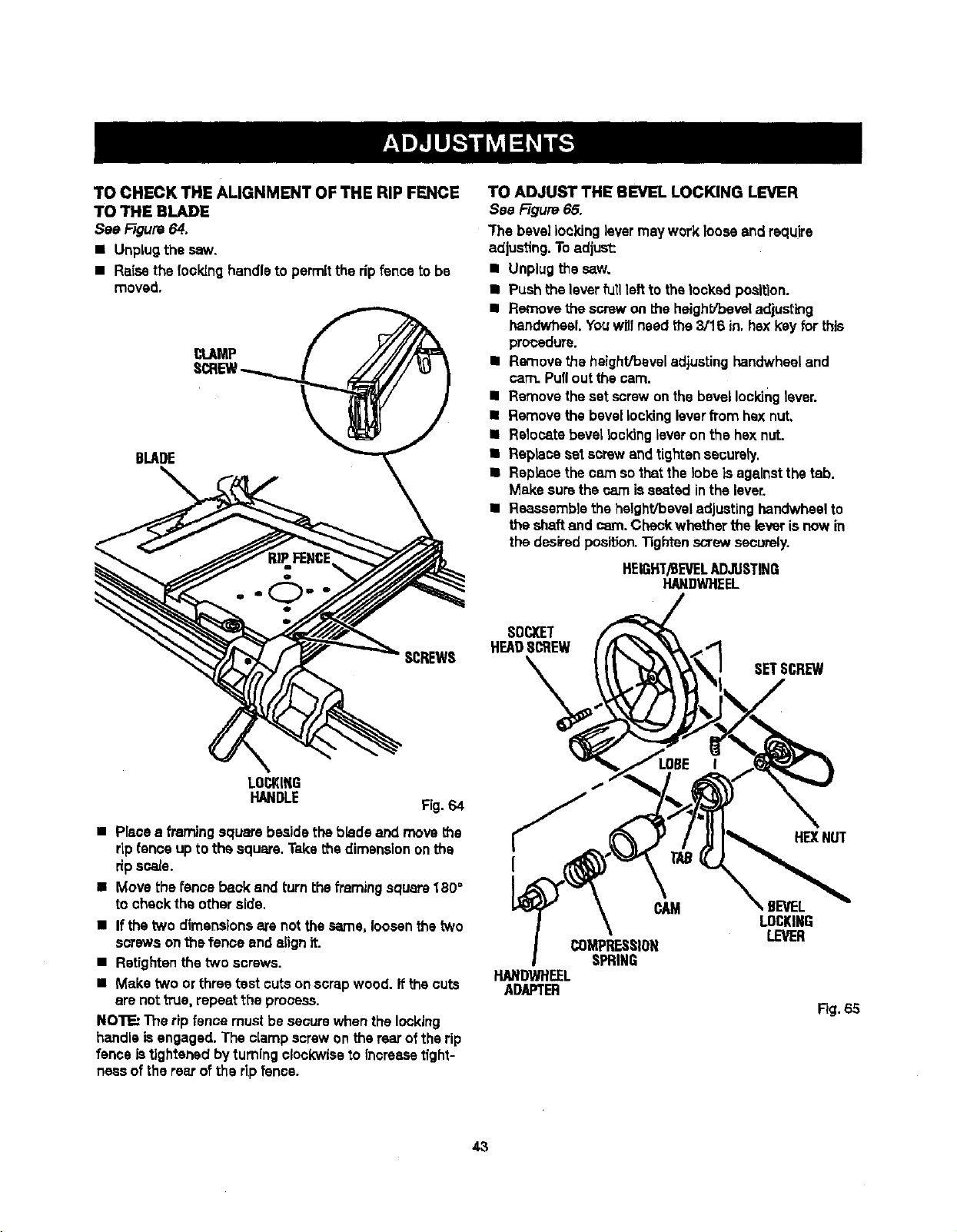
TOCHECKTHEALIGNMENTOFTHERIPFENCE
TOTHEBLADE
SeeFigure 64.
• UnpLugthe saw.
• Raisethe (ooking handleto permitthe ripfence tobe
moved.
BLADE
SCREWS
TO ADJUST THE BEVEL LOCKING LEVER
See FTgura65.
"Fhebevel lookinglevermay work looseand require
adjusting.Toadjust:
• Unplug thesaw.
• Push the leverfull leftto thefecked position.
• Remove the screwon t_e heighS_beveladjusting
handwhaeLYouwritneed the3/16 in,hex keyfor this
procedure.
• Removethe height/bevel adjustinghandwhseland
cam. Pullout the cam.
• Remove the set screwonthe bevel lockinglever.
• Remove the bevellockingleverfrom hex nut,
II Relocatebevel locking leveron the hsx nut.
• Replace set screwandtighten securely.
• Replacethe cam sothat the lobeis againstthe tab.
Make surethe cam isseated inthe lever.
• Reaseemb)sthe height/bevel adjustinghandwheelto
the shaftand cam. Checkwhether the leverisnow in
the desiredposition.Tightenscrewsecurely.
HEIGHT/BEVELADJUSTING
HANOWHEEL
SOCKET
H_DS_EW
SETSCREW
LOCKING
HANDLE Fig.64
• Placea framing squarebeside theblade and movethe
rLpfence up tothe square. Takethe dimensiononthe
ripscale.
• Move thefence back and turnthe framing square180°
to checkthe otheraide.
• If thetwo dimensionsare not the same, loosenthe two
s_'ewa on_s fence end alignit.
• Retightenthe two screws.
• Make two or three test cutson scrapwood. it thecuts
are not true,repeat the process.
NOTE: The rip fence must besecurewhen the locking
handle isengaged.The clamp screwon the rearofthe rip
fence istightened byturningclockwiseto increasetight-
nessof the rearof the ripfence.
CAM
COMPRESSION
SPRING
HANDWHEEL
ADAPTER
HEXNUT
,BEVEL
LOCKING
LEVER
Fig.65
43
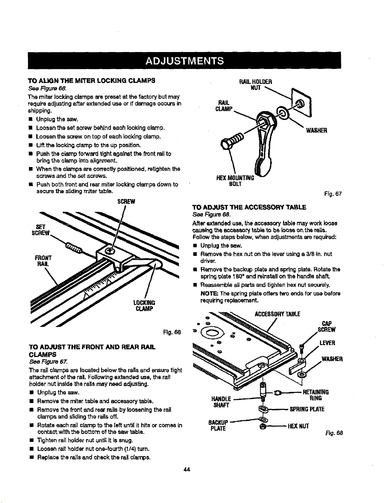
TOAUGNTHEMITERLOCKINGCLAMPS
See Figure66.
The miter locking clamps are preset at thefactory but may
requireadjustingafter extendeduse or if damage occursin
shipping.
• Unplug the saw.
• Loosen theset screwbehindeach lockingclamp.
• Loosen thescrew on top of each Iockingclamp.
• Uft the locldng clamp tothe up position,
• Push the clamp forward tightagainst the front railto
bringthe c_p intoaiigr_'_ent.
• When the clamps are correctlypositioned,retightenthe
scows and the setscrews.
• Push both front and rearmiter lockingclampsdown to
securethe s|idingmiter table.
SCREW
Fig. 66
TO ADJUST THE FRONT AND REAR RAIL
CLAMPS
See Rgure 67.
The railcrampsate locatedbelow theraUsand ensuretight
attachment of the rail.Followrngextended use, the rail
holdernutinsidethe railsmay need adjusting.
• Unplug the saw.
• Remove the miter table and accessorytabla.
• Remove the _ont emdrear railsbylooseningthe rail
crampsand dlding the rai_soff.
• Rotate eachrailclamp to the {sft unti{ithits orcomes in
correct with the bo'_omotthe saw table.
• Tightenraitholdernut untilit issnug.
• Loosen railholdernutone-fourth (1/4)turn.
• Replacethe rails and checkthe rail clamps.
44
RAILHOLOER
NUT
RAIL
CLAMP
WASHER
HE)(MOUNTING
BOLT
Fig. 67
TO ADJUST THE ACCESSORY TABLE
See Rgure 68.
After extended use, the acce..-_, tab/emay workloose
caus(_ th_accessorytable to be {oos_o_ the ra'_s.
Foi(owthestepsbelow,when adjustmentsarerequired:
• Unplugthesaw.
• Removethe hexnut on the leverusings 3/8 in. nut
driver.
• Removet_e backup p{ateand springplate.Rotate the
springplate 180° and reinstallon the handleshaft.
• Reassemble allparts end tightenhexnut securely.
NOTE; The springplate offerstwo endsfor use before
re_[uiringreplacement.
ACCESSORYTABLE
LEVER
HAl RING
_"IAFT
SPRINGPLATE
BACKUP
PLATE HEXNUT
F_.68
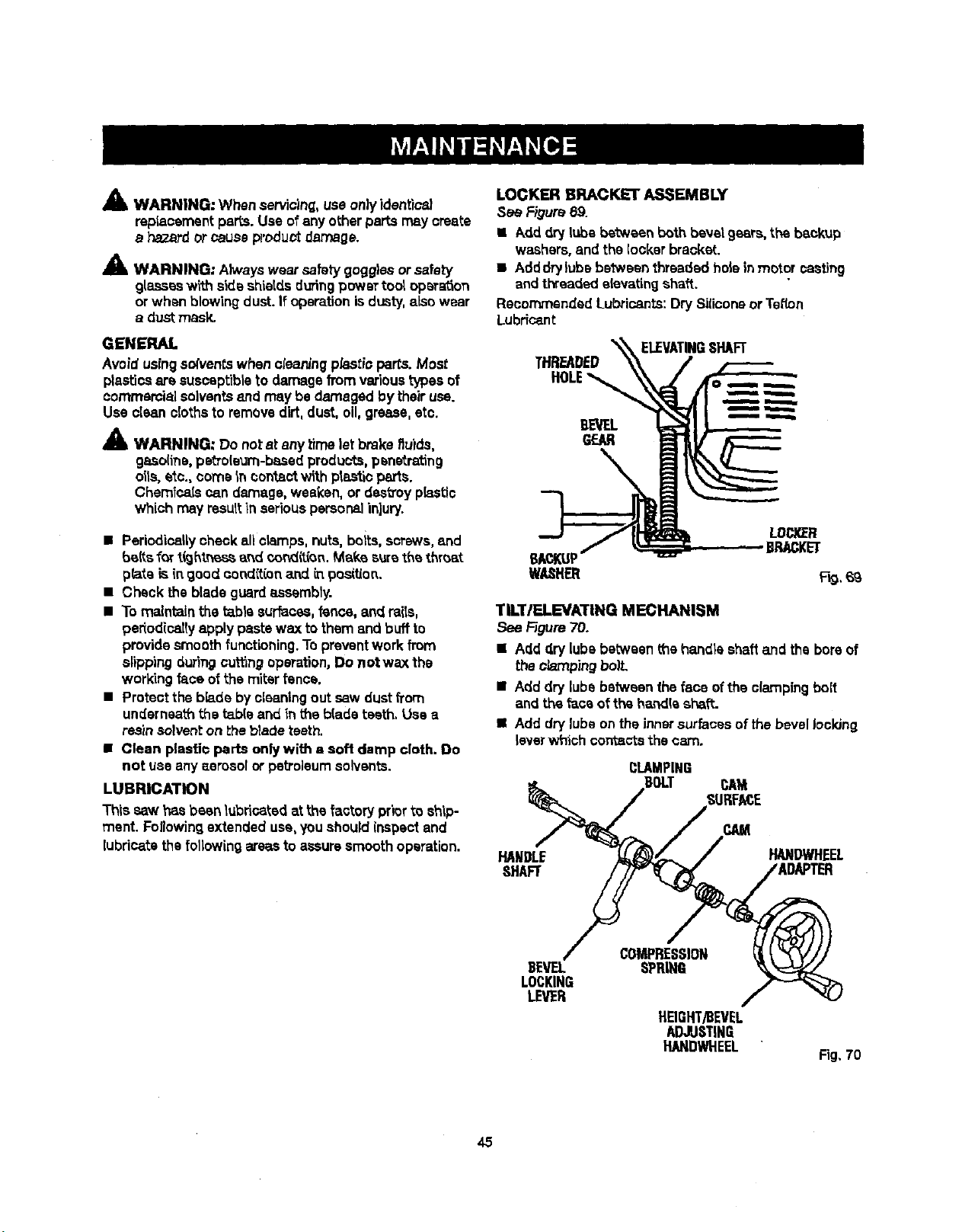
A
Am, WARNING: Whenservicing,useonlyidentice_
repianementpaps. Use ofany otherparts m_y create
a hazardorcauseproduct damage.
A
Am. WARNING: A_vays wear safetygoggles orsafety
glasses with side shietdsduringpower too_opera,on
or when blowing dust.If operationisdusty,also wear
a dust mask.
GENERAL
Avoid usingso(ventswhen cteaning p_,stioparts. Most
plasticsare suscsptibteto damage fromvarioustypes of
commercialsolventsend may be damaged bytheiruse.
Use clean clothsto removedirt,dust, o11,grease,etc.
_1_ WARNING: Do not at any Limeletbrake fluids,
gaso(ine,petro(eum-basedproducts,penetrating
oils, etc., come In ¢on_actwith pta_'=oparts.
Chemicatscan damage,weaken, or destroyp_stic
which may resuttIn seriouspersonalinjury.
• Periodicallycheckallclamps,nuts,boits, screws,and
_{ts _art_hl.r_ss and cond_,_n,Make sure the t_roat
p_te is(ngood cond(t(on a.nd_. position.
• Check theblade guardassembty.
• To maintain the t_btesur_css, fence, and raits,
pedodice]Iyapplypastewax tothem and buff to
providesmoothfunctioning. Topreventwork from
slippingduringcuttingoperation,Do not wax the
workingface ofthe miter fence.
• Protect thebb.de by cleaningout saw dustfrom
underneaththe _b(e and in the b{ade teeth. Use a
reamsolventon _heb_adeteeth.
• Clean plastio parts onlywith a soft damp cloth. Do
not use anyaerosol or petroleumsolvents.
LUBRICATION
This saw has been lubricatedatthe factory priorto ship-
ment. Foflowingextended use,you shouldinspectand
lubricatethefollowing areasto assure smoothoperation.
LOCKER BRACKET ASSEMBLY
See Figure69.
• Add dry lubebetween both bevel gears, theb_ckup
washers,and the locker braoket..
• Adddrylubs be_:weenthreaded hole in motor casting
andthreaded elevatingshaft.
RecommendedLubricants:Dry Siliconeor Tenon
Lubricant
THREADED
HOLE
BEVEL
GEAR
ELEVATINGSHAFT
TILT/ELEVATING MECHANISM
See _gure 70.
• Add dry [ubebetween me handle shaftand the boreof
the P.,bmpingboil
• Add dry lube between the face ofthe clampingbolt
and theface of the handle sh_ft.
• Add dry lubeon theinnersurfacesofthe bevel Ioclong
leverwhich corr_sctsthe cam.
CLAMPING
BOLT CAM
SURFACE
HANDLE
SHAFT
CAM
HANDWHEEL
BEVEL
LOCKING
LEVER
COMPRESSION
SPRING
HEIGHT/BEVEL
ADJUSTING
HANDWHEEL
Fig. 70
45
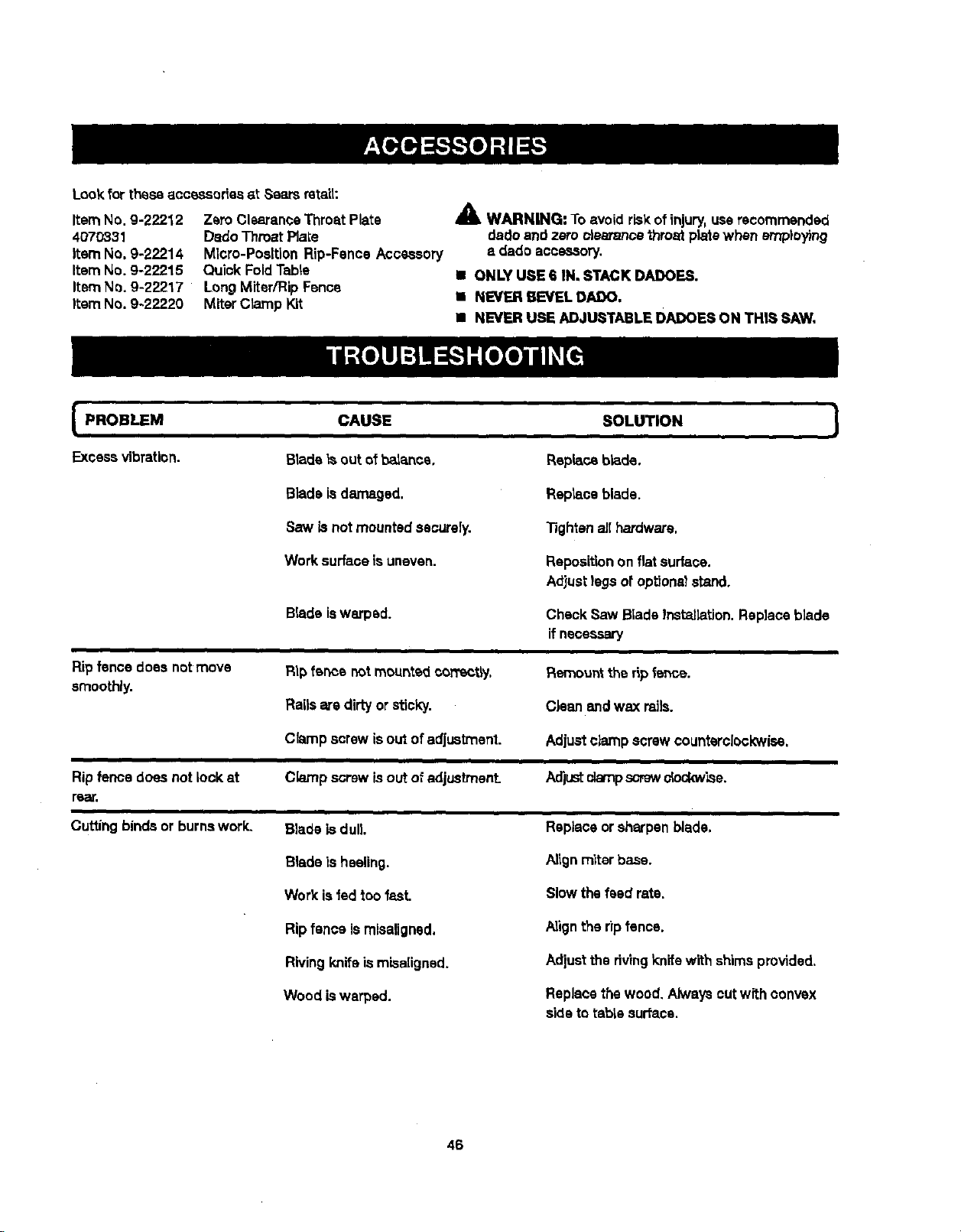
Lookfortheseaccessories at Searsrata'd:
Item No. 9-22212
4070331
Item No. 9-22214
Item No. 9-22215
Item No. 9-22217
Item No. 9-22220
ZeroClearanceThroat Plate
DadoThroat Plate
Micro-Position Rip-Fence Accessory
Quick FoldTable
Long Miter/Rip Fence
MiterClamp Kit
A
41& WARNING; To avoid riskofinjury,userecommended
dadoand zero clearance throatplatawhen amp}eying
a dado accessory.
I ONLY USE 6 IN. STACK DADOES.
',= NEVER BEVEL DAJDO.
• NEVER USE ADJUSTABLE DADOES ON THIS SAW,
PROBLEM CAUSE SOLUTION ]
Excessvibration. Bladeis out ofbalance, Replaceblade.
Bladeisdamaged. Replaceblade.
Saw is notmounted securely. Tightenall hardware.
Worksurfaceis uneven. Repositionon flat surface.
Ripfence does not move
smoothly.
Rip fence does not lock at
rear.
Adjustlegs of op_onslstand.
Check Saw BladeInst_la_on. Replaceblade
if necessary
Remounttheripfence.
Cleanand wax mils.
Adjustclamp screw counterclockwise,
Adiustclamps_ew clockwise.
Cuttingbinds or burnswork,
Bladeiswarped.
Rip fence not mounted c,on'e_tLy.
Railsare dirtyor sticky.
Clamp screw isout of adjustment.
Clamp screw isout of adjustment.
Blade is dull.
Blade is heeling.
Workisfed too fast
Rip fence ismisaUgned.
Rivingknifeismisaligced.
Wood iswarped.
Replaceorsharpen blade,
Alignmiterbase.
Slowthe feed rats.
Align the _lpfence.
Adiust the dvlng knife with shimsprovided.
Replacethe wood. Alwayscutwith convex
sideto table surface.
46
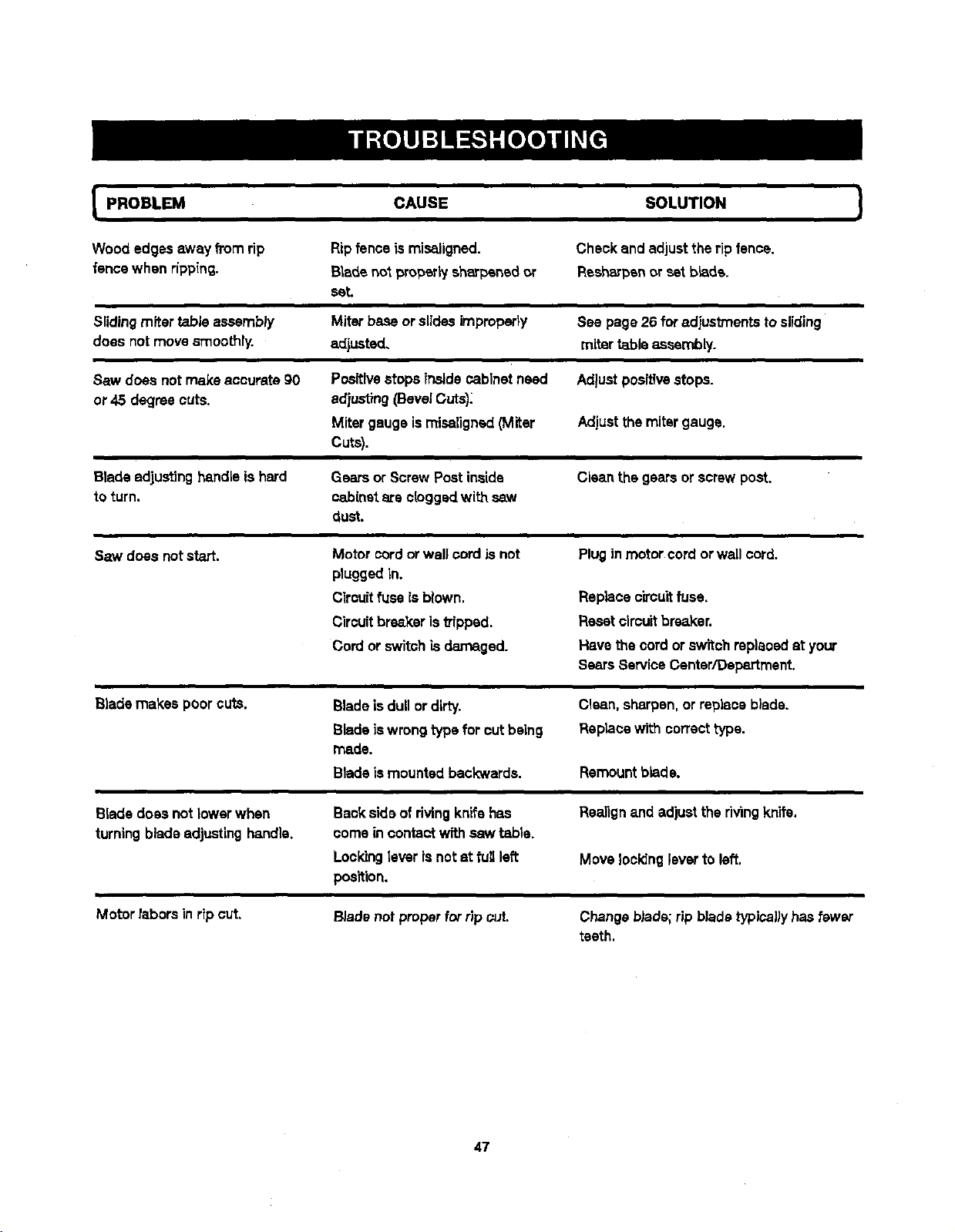
I PROBLEM CAUSE SOLUTION !
Wood edges away fromrip Ripfence is misaligned. Check and adjustthe ripfence.
fencewhen ripping. Blade not properlyeh,_rpenedor Reeharpenor set blade.
set,
Slidingmiter table aSSembly Miterbase orslidesimproperly See page 26 for adjustments tosliding
does not movesmoothly, adjusted, miter table assembLy.
Saw does not make accurate 90 Posltlvestops insidecabinetneed Adjustpositivestops.
or 45 degree cuts. adiusting(BevelCuts):
Miter gaugeismisaligned(Miter Adjustthe mitergauge.
Cuts).
Blade adjustinghandleis hard Gears or ScrewPost inside Clean thegears or screwpoet.
to turn, cabinetare ckiggsd with
dust.
Saw does notstart. Motor cordor wall cord isnot Plugin motor cordor wall cord.
pluggedin.
Cirouitfuse isblown.
Circuitbreakeristripped.
Cordor switch isdamaged.
Replace circu'_fuse.
Resetcircuitbreaker.
Have the cordor switchreplacedat your
SearsServiceCenter/Department.
Blade makes poor cuts.
Bladeisdull ordirty.
Blade is wrongtypefor cutbeing
made.
Bladeismounted backwards.
Clean, sharpen,or replaceblade.
Replacewith correcttype.
Remountblade.
Bladedoes not lowerwhen
turning bladeadjustinghandle.
Backside of rivingknifehas
comein contact wff.hsaw table.
Lockinglever is notat full left
position.
Realignand adjusttherivingknife.
Move _ockingleverto left.
Motor taborsinrip cut,
BJadenotproper for ripcut. Change blade; rip blade typicallyhas fewer
teeth.
47
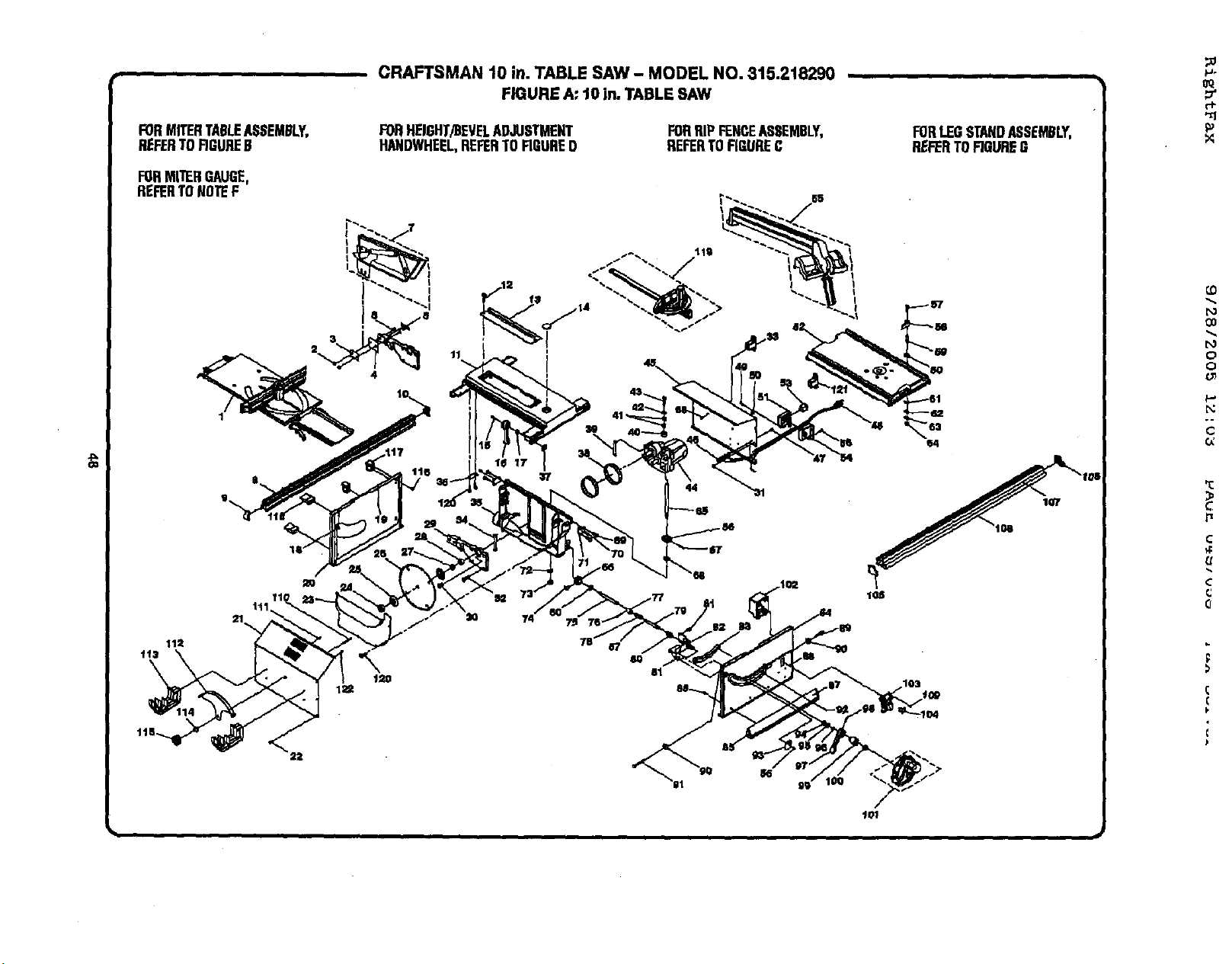
FORMITERTABLEASSEMBLY,
REFERTDRRUREB
FORMITERGAUGE,
REFERTONOTEF
CRAFTSMAN 10 in. TABLE SAW - MODEL NO. 315.218290 ,
FIGURE A"10 in. TABLESAW
FORHEIGHT/BEVELADJUSTMENT
HANDWHEEL,REFERTORGURE0
FORRIPFENCEASSEMBLY,
REFERTORGUREC
11
ld 12
44
120
8O
81
i
FORlEG STANDASSEMBLY,
REFERTORGURBG
107
F)
0
o
0:
r_
¢
c
Q
(
(
F
€
107
#
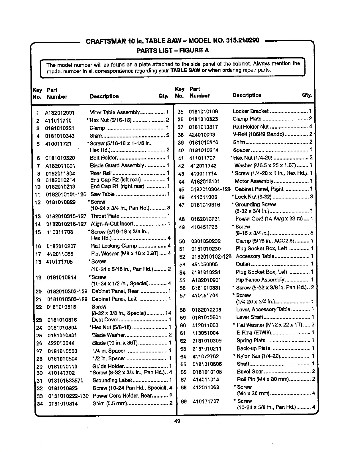
[
CRAFTSMAN 10 in. TABLE SAW - MODEL NO, 3t5.2t8290
PARTS LIST - FIGURE A
The model numberwill be found on a plate attached to the side panelof the cabinet. Alwaysmention the |
model numberin allcorrespondenceregardingyourTABLESAW orwhen orderingrepairparts.
J
Key Part Key Part
No. Number Description Qty, No. Number Deacrlp6on Qty
1 A182012001
2 411O1171O
3 0181010321
4 0181010343
5 410011721
6 0181010320
7 A182011001
8 0182011804
g 0182010214
10 0182010213
1t 0182010101-126
Miter TableAssembly................. 1
"Hax Nut (5/16-18) ...................... 2
Clamp........................................ 1
Shim........................................... 5
*Screw (5/16-18 x 1-1/8 in.,
HexHd.)..................................... 2
BoltHolder................................. 1
BladeGuardAssembly.............. 1
Rear Raft.................................... 1
End Cap R2 (leftrear) ............... 1
End Cap R1 (rightreef) ............. 1
Saw Table .................................. 1
12
13
14
15
16 0182010207
17 412011065
18 410171705
19 0181010514
20 0182010302-129
23 0381010303-129
22 0181010815
23 0181010316
24 0181016504
25 0181010401
26 422010044
27 0181010503
28 0181010504
29 0181010110
30 410141702
31 918101533570
32 O181O1O823
33
34
018t 0_,0329 *Screw
(10-24 x 3/4 in., Pan Hd.)........... 3
0182010315-127 Thmat Plate ............................... 1
0182010216-127 Atign-A.-Cutinsert...................... 1
410011708 *Screw (5/16-18 x 3/4 in.,
HexHd.)..................................... 4
Rail LockingClamp.................... 4
Rat Washer(M8 x 16 x o.8"r)..... 4
• screw
(10-24 x 5/16 in.,Pan Hd.)......... 2
"Screw
(10-24 x 1/2 in.,Special)............ 4
Cabinet Panel,Rear .................. 1
Cabinet Panel, Left ................... 1
Screw
(8-32 x 3/8 in., Specia0............ 14
Dust Cover................................. 1
• He}(Nut {5/6-18) ........................ 1
B_adeWasher............................. 2
Blade(10 in. x 36T).................... 1
1/4 in.Spacer ........................... 1
112in. Spacer ............................ 1
GuideHolder.............................. 1
•Screw(8-32 x 314in., Pan Hd.).. 4
GroundingLabel........................ 1
Screw (t0-24 Pan Hd., Special). 4
01310"t0222-130 PowerCord Holder,Rear........... 2
0181010514 ShPn(0.5 ram)............................ 2
35 0181010106
36 0181010323
37 0181010317
38 424010003
39 0181010310
40 0181010214
41 411011707
42 412011743
43 410011714
44 A182010101
45
46
47
LockerBracket.......................... 1
ClampPlate ............................... 2
RailHolderNut .......................... 4
V-Belt (106H9 Bando}................ 2
Shim........................................... 2
Spacer....................................... 1
• Hsx Nut {1/4-201........................ 2
Washer(M6.5 x 25 x 1.6T)........ 1
* Screw(1/4-20 x 1 in.,Hex Hal.).1
Motor Assembly........................ 1
0182010304-129 Cabinet Pa_l, Right ................ 1
411011006 "Lock Nut (8-32) ......................... 3
0181010816 * GroundingScrew
(8-32 x 3/4 tn.)........................... 1
48 01820'_0701 PowerCord (14 Awg x 33 m).... 1
49 410451703 * Screw
(8-t6 x 3/4 in.)........................... 5
50 0301030202 Clamp (5/16 in., ACC2,5).......... 1
51 0181010230 PlugSocket Box,Left .............. 1
52 0182010102-126 AccessoryTable........................ 1
49
53 451050005
54 0181010231
55 A182010901
56 O181O10831
57 410151704
58 01820102D8
59 0181010501
60 412011063
61 413051004
62 0181010309
63 0181010211
04 411072702
65 0181010606
66 0181010105
67 414011014
68 412011063
, 69 410171707
Duffer........................................ 1
PtugSocket Box, Left .............. 1
RipFence Assembly ................. 1
" Screw(8-32 x 3/3 in. PanHal.)..2
SGrew
(1/4-20 x 3/4 in.)........................ 1
Lever,Accessory "fable............. 1
Lever Shaft................................
* Rat Washer_Vll2 x 22 x I"P).....3
E-Ring(ETW8)........................... 1
SpringPIate ..........=................... 1
Back-up Plate........................... 1
* NylonNut (1/4-20)..................... 1
Shaft.......................................... 1
BevelGear................................ 2
Rot;Pin (M,4x 30 mm)............... 2
* Screw
_4x2o ram)............................4
" Screw
(10-24 x 5/8 in., Pan Hd.).......... 4
#
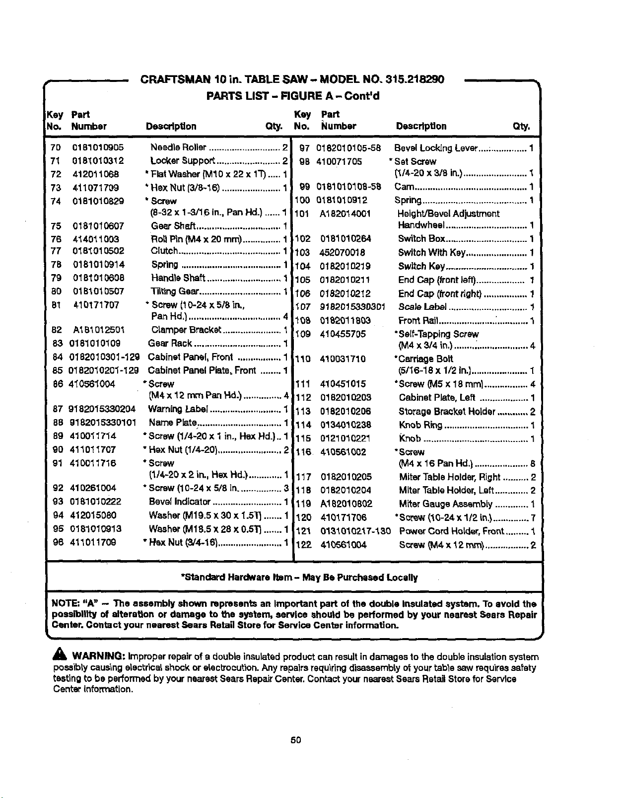
p_
Key Part
No, Number
CRAFTSMAN 10 in. TABLE SAW - MODEL NO. 3t5.218290
PARTS LIST - FIGURE A - Cont'd
Key Part
Description Qty. No. Number Description
Qty.
70 0181010905
71 0181010312
72 412011O68
73 411071709
74 0181010829
75 0181010607
76 414011003
77 018_010502
78 0181010914
79 0181010608
80 0181010507
81 410171707
82 A181012501
83 0181010109
84 0182010301-129
85 0182010201-129
86 4_0561004
87 9182015330204
88 9182015330101
89 410011714
90 411011707
91 410011716
92 410261004
93 0181010222
94 412O15O80
95 0181010913
96 411011709
Needle Roller............................ 2
Locker Support ......................... 2
' Flat Washer (IV110x 22 x 1"1")._.. 1
*Hex Nut (3/8-16) ....................... 1
* Screw
(8-32 x 1-3/16 in., Pan Hd.) ...... 1
Gear Sh_t ................................. 1
Roll P_n(M4 x 20 ram)............... 1
Clutch........................................ 1
Spring....................................... 1
Handle Shaft............................. 1
"131_ingGear................................ 1
* Screw(t 0-24 x 5/8 in.,
Pan Hd.).................................... 4
Clamper Bracket ....................... 1
Gem Reek................................. 1
Cabinet Panel, Front ................. 1
Cabinet Panel Plate, Front ........ 1
* Screw
(M4x 12 mm PanHd.')............... 4
WarningLabel ............................ 1
Name Pb,te ................................. 1 i
*Screw (1/4-20 x 1 in., Hex Hd.),. 1 ]
"Hex Nut (1/4-20)......................... 21
* Scow
(114-20x 2 in.. Hex Hd.) ............. 1
*Screw (10-24 x 5/8 in................. 3
Bevel Indicator ........................... 1
Washer_M19.5x 30 x 1.5"1_....... 1
Washer_M18,5x 28 x 0.5_ ....... 1
• Hsx Nut (3/4-16)......................... 1
97 0182010105-58
98 410071705
99 0181010108-58
100 0181010912
101 A182014001
102 0181010264
103 452070018
104 0182010219
105 0182010211
106 0182010212
107 9182015330301
108 0182011803
109 4104-55705
110 410031710
111 410451015
112 0182010203
113 0182010206
114 0134010238
115 0121010221
116 410561002
117 0182010205
118 0182010204
119 A1820!0802
120 410171706
121 0131010217-130
122 410561004
Bevel LockingLever....;.............. 1
* Sat Screw
(1/4-20 x 3/8 in.)......................... 1
Cam............................................ 1
Spdng......................................... 1
Height/BevelAdjustment
Handwhesl................................ 1
SwitchBox................................ 1
SwitchWith Kay........................ 1
Switch Key............................... 1
End Cap (front}aft)................... 1
End Cap (front right)................. 1
Sca/e Label ............................... !
Fro_ Rail......................:............ "_
*Self-TappingScrew
(M4 x 3/4 in.)............................. 4
*Cerria0s Bolt
(5/16-18 x 1/2 in,]...................... 1
"Screw (MSx 18 mini ................. 4
Cabinet Plate, Left ................... 1
Storage BmcY,eI Holder............ 2
KnobRing................................. 1
Knob ......................................... 1
• Screw
(M4 x 16 Pan Hd.)..................... 8
MiterTableHolder,Right.......... 2
MiterTableHolder,Left............. 2
MiterGauge Asssmbly............. 1
*Screw (10-24 x 112in,_.............. 7
Power Cord Holder, Fmr_t.......... "t
Screw_M4x 12 ram}................. 2
*Standard Hardware Item - May Be Purchased Locally
NOTE: "A" - The assembly shown represents an Important part of the double Insulated system. To avoid the
possibility of alteration or damage to ttte system, service should be performed by your nearest Sears Repair
Center. Contact your nearest Sears Retail Store for Service Center information.
b
_1, WARNING: Improper repairof a doubleinsulatedproductcanresultin damagesto thedoubleinsulationsystem
possiblyceus'lng electricalshock or eLactrocu(ion.Any repairsrequiringdisaessm'o_yot yourtable saw requiressafety
testing to be performedby yournearestSears RepairCenter. Contactyour nearestSearsRatanStorefor Service
Center information.
5O
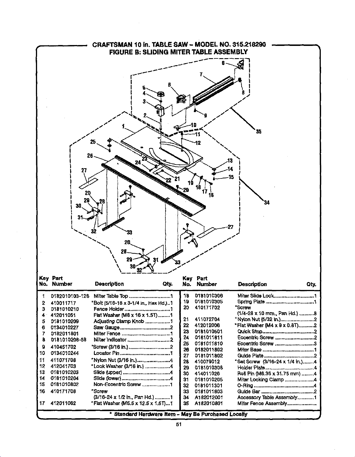
CRAFTSMAN 10 in. TABLE SAW- MODEL NO. 815.218290
FIGURE B: SLIDING MITER TABLE ASSEMBLY
I
I
I
I
I
I
%
I
I
l
2o
k ,
\
\
\
\
Key Part
No. Number Deecdptlon
j-
Key Part
Qty. No. Number
Description Qty.
1
2 410011717
3 0181010210
4 412011051
5 0181010209
6 0134010227
7 0182011801
8 0181010208-58
g 410451702
10 0134010244
11 4110TIT08
12 412041T03
13 0181010203
14 0181010204
15 0181010802
16 410171708
1T 412011062
0182010103-126 Miter Table "l'op.............................. 1
*Boll:(5/I6-18 x 3-1/4 in., Hex Hd_..1
Fence Holder ................................. 1
Fb_ Washer (M8 x 16 x 1.5T)......... 1
Adjusting Clamp Knob .................. 1
Saw Gauge .................................... 2
Miter Fence ................................... 1
_l_er Indicator ............................... 2
'Screw (3/16 In.).............................. 2
Locator Pin .................................... 1
"Nylon Nut (3/16 in.)........................ 4
° Lock Washer (3/16 in.) .................. 4
Slkla (upper} .................................. 4
Slide (lower)................................... 4
Non-Eccen_'fo Sorew .................... 1
_Screw
(3/16-24 x _/2 In., Psn Hd.) ........... 1
* Flat Washer (M5.5 x 12.5 x 1.5T)...1
18 0181010306
19 0161010305
20 410171702
21 411072704
22 4120120C6
23 0181010601
24 018_011811
25 0181011810
26 0182011802
27 0181011802
28 410079012
29 01810_6308
30 414011026
31 0181010205
32 0181011301
33 0181011803
34 A182012001
35 A182010801
Miter Slide Loc_............................. 1
Spring PI;_ts................................... 1
*Screw
(1/4-28 x 10 rrcn., Pan Hd.) ......... -8
"N_on Nut (5/32 In.)....................... 2
"Flat Washer (M4 x 9 x 0.BT).......... .2
Quick Stop.....................................2
EocentricScrew ............................ 2
Eccentric Screw ........................... 3
Miter Base ..................................... 1
Guide Plate................................... .2
"SetScrew (3/16-24 x 114In.)........4
HoLder Plate ................................... 4,
Roll Pin (M6.35 x 31.75 ram) ......... 4
MitBrLocking Cbmp ..................... 4
O-Ring ........................................... 4
Guide Bar.................................... .2
Aocsesory Table Assembly............ 1
Miter Fence Assembly.....................
* Standard Hardware Item - Mey Be Purchased Locally
51
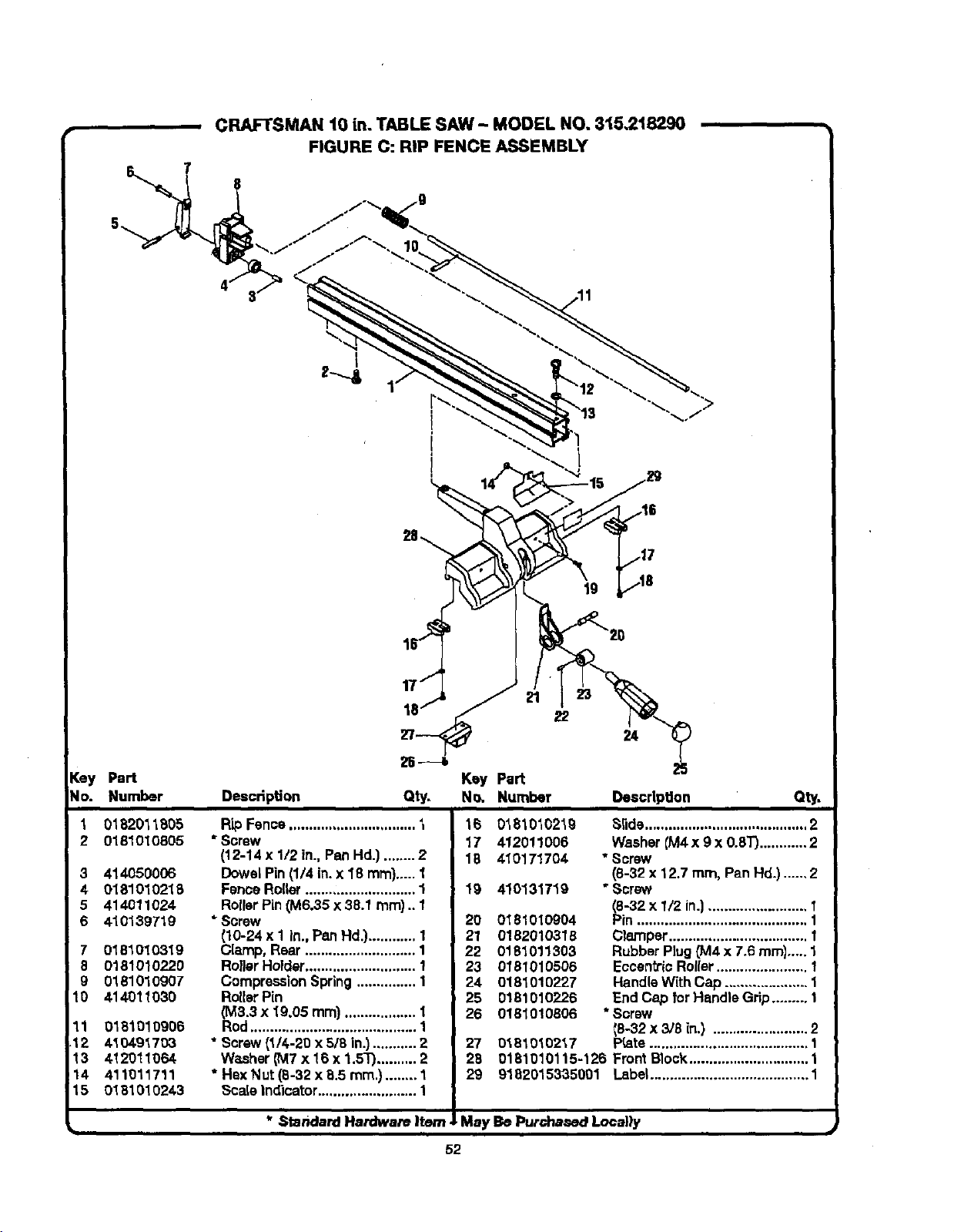
, CRAFTSMAN 10 in. TABLE SAW - MODEL NO. 315.218290
FIGURE C: RIP FENCE ASSEMBLY
8
[ey Part
No. Number
"L 0182011805
2 0181010805
3 414050006
4 0181010218
5 414O11024
6 410139719
7 0181010319
8 0181010220
g 018101O9O7
10 414011030
11 0181010906
12 4104.91703
13 412011064
14 411011711
15 0181010243
Description
Key Part
Qty. No. Number
Description Qty.
Rip Fence................................ t
* Screw
(12-14 x 1/2 in., PenHd.) ........ 2
DowelPin(1/4 in.x 18 ram).....1
FenceRoller............................ 1
RollerPin(M6.35 x 38.1 ram).. 1
* Screw
{10-24x 1 in., Pe.nHd.}............ 1
Clamp, Rear ............................ 1
RollerHolder............................ 1
CompressionSpring ............... 1
RollerPin
(M3.3 x 19.05 ram).................. 1
Rod.......................................... 1
* Screw(1/4-20 x 5/8 in.)........... 2
WasherCM7x 16 x 1.5_ .......... 2
* Hex Nut (8-32 x 8.5 ram.)........ 1
16 0181010219
17 412011006
18 410171704
19 410131719
20 0181010904
21 0182010318
22 0181011303
23 0181010506
24 0181010227
25 0181010228
26 0181010806
27
28
29
0181010217
S_ide......................................... 2
Washer {M4x 9 x 0.8T)............ 2
• Screw
(8-32 x 12.7 turn, PanHd.) ...... 2
"Screw
(8-32 x 1/2 in.)......................... 1
Pin ........................................... 1
Clamper................................... I
Rubber Plug_14 x 7.6 mini..... 1
Eccen_i¢ Rol{er....................... 1
HandleWith Cap ..................... 1
End Cap for Handle Grip......... 1
* Screw
_p8-32x 3/8 in.) ........................ 2
_ate........................................ 1
0181010115-126 Front Block.............................. 1
9182015335001 Labe_........................................ 1
Scale indicator ......................... 1 I
I
* ._tandard Hardware Item JLMay Be Purdnaaed Locally
52
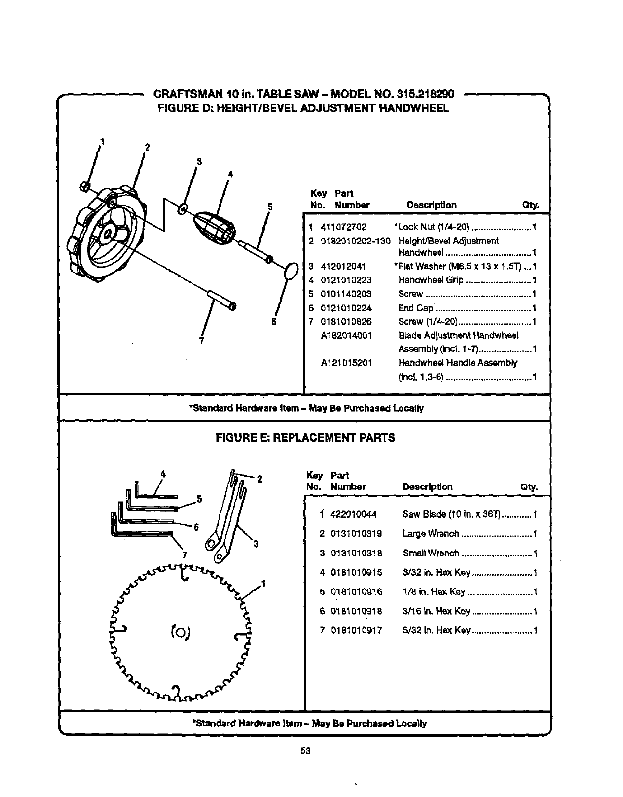
CRAFTSMAN t0 in. TABLE SAW - MODEL NO. 3t5.218290
FIGURE D: HEIGHT/BEVEL ADJUSTMENT HANDWHEEL
1
/ I'p,
5 No, Number
3 412012041
4 0121010223
5 0101140203
6 0121010224
7 0181010826
A182014001
A121015201
Oescdpgon Qty.
1 411072702 *Lock Nut (1/4-20) ........................ 1
2 0182910202-!30 HeighVBevelAdjustment
Handwheel.................................. 1
*Rat Washer(M6.5 x 13 x 1.5"r) ...1
HandwheelGrip.......................... 1
Screw.......................................... I
EndCap. ..................................... 1
Screw (1/4-20)............................. 1
Bride AdiustmentHandwheel
Assembly(.Incl.1-7).....................1
HandwheelHandleAssembly
(Incl. 1,3-6) .................................. 1
"Standard Hardware Item - May Be Purchased Locally
FIGURE E: REPLACEMENT PARTS
\
1
Key Part
No. Number
2
3
4
5
6
7
DescripSon Q_.
422010044
0131010319
0131010318
0181010915
0181010916
0181010918
0181010917
Saw Blade (10 in.x 36"i_............ 1
Large Wrench............................ 1
SmallWrench ............................ 1
3/32 in. Hax Key........................ 1
1(8 in. Hex Key .......................... 1
3/16 in. Hex Key ........................ 1
5/32 in,Hex Key........................ 1
"Standard Hardware ]tam - May Be Purchased Locally
tl
53
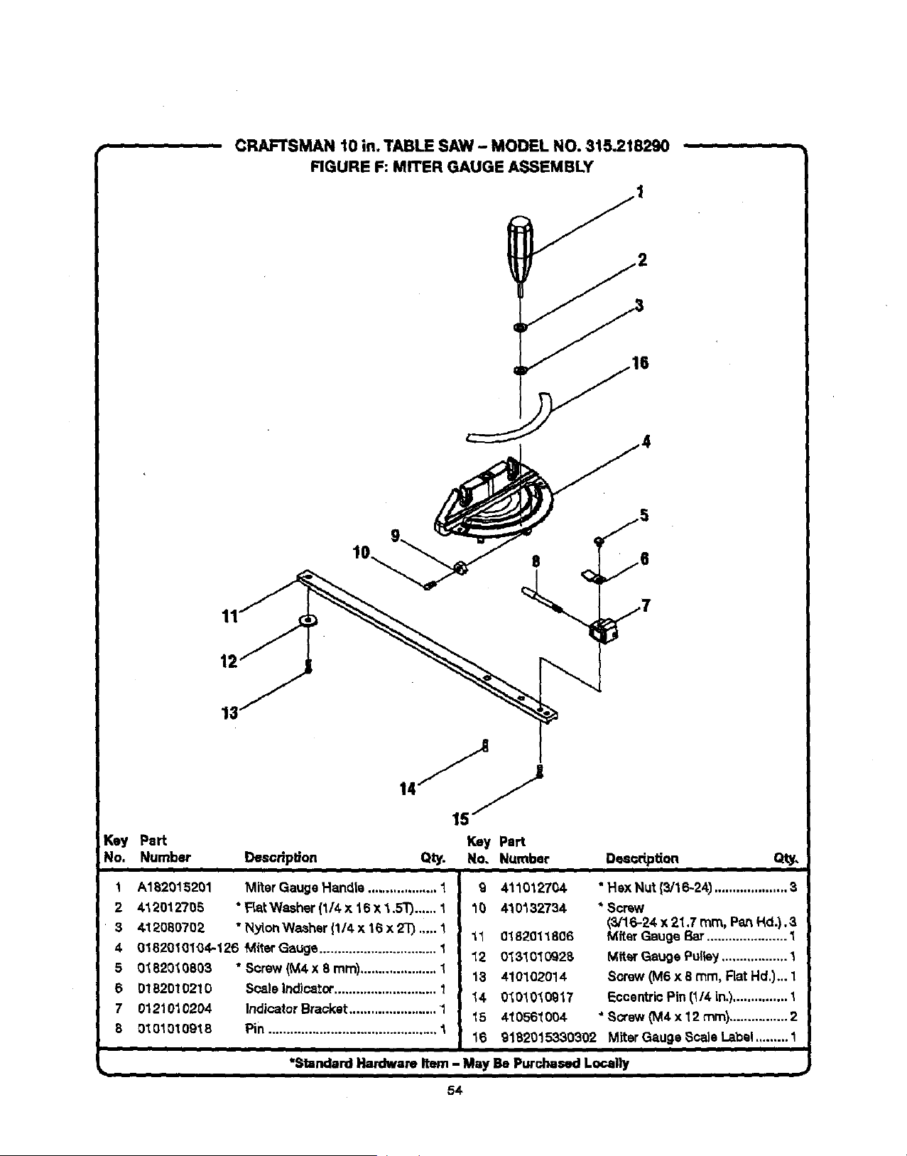
CRAFTSMAN 10 in. TABLE SAW - MOOEL NO. 815.218290
FIGURE F: MITER GAUGE ASSEMBLY
11
12
_ey Pert
No. Number Desoripl_on
Key Part
Qty. No. Number Des_dptian
1 A182015201 Miter Gauge Handle ................... 1
2 4_,2012705 * FLa_Washer (1/4 x 16 x 4,.5T)...... 1
3 &12080702 "Nylon Washer{1/4 x 18 x 2"0.,...1
4 01820101_4-126 M{terGauge ................................ I
5 0182010803 "Screw (M4 x 8 mm)..................... 1
6 01B2010210 Scale Indicator............................ 1
7 01210_,0204 IndicatorBracket........................ 1
8 01010t09t 8 Pin .............................................. 1
Q 411012704
10 410132734
11 01820118O6
12 0131010928
13 410102014
14 0101010917
15 410561004
16
• Hex Nut {3/16-24) .................... 3
* Sorew
(3/16-24 x 21,7 ram, PartHd.).3
Mfter Gauge Bar...................... 1
Miter Gauge Pulley.................. 1
Screw (M6 x 8 ram, Flat Hd.)... 1
EccentricPin (1/4 in.)............... 1
* Scow _M4x 12 ram)................ 2
glB2015330302 MiterGauge ScaleLabel.........1
"Standard Hardware Item - May Be Purchased Locally
54
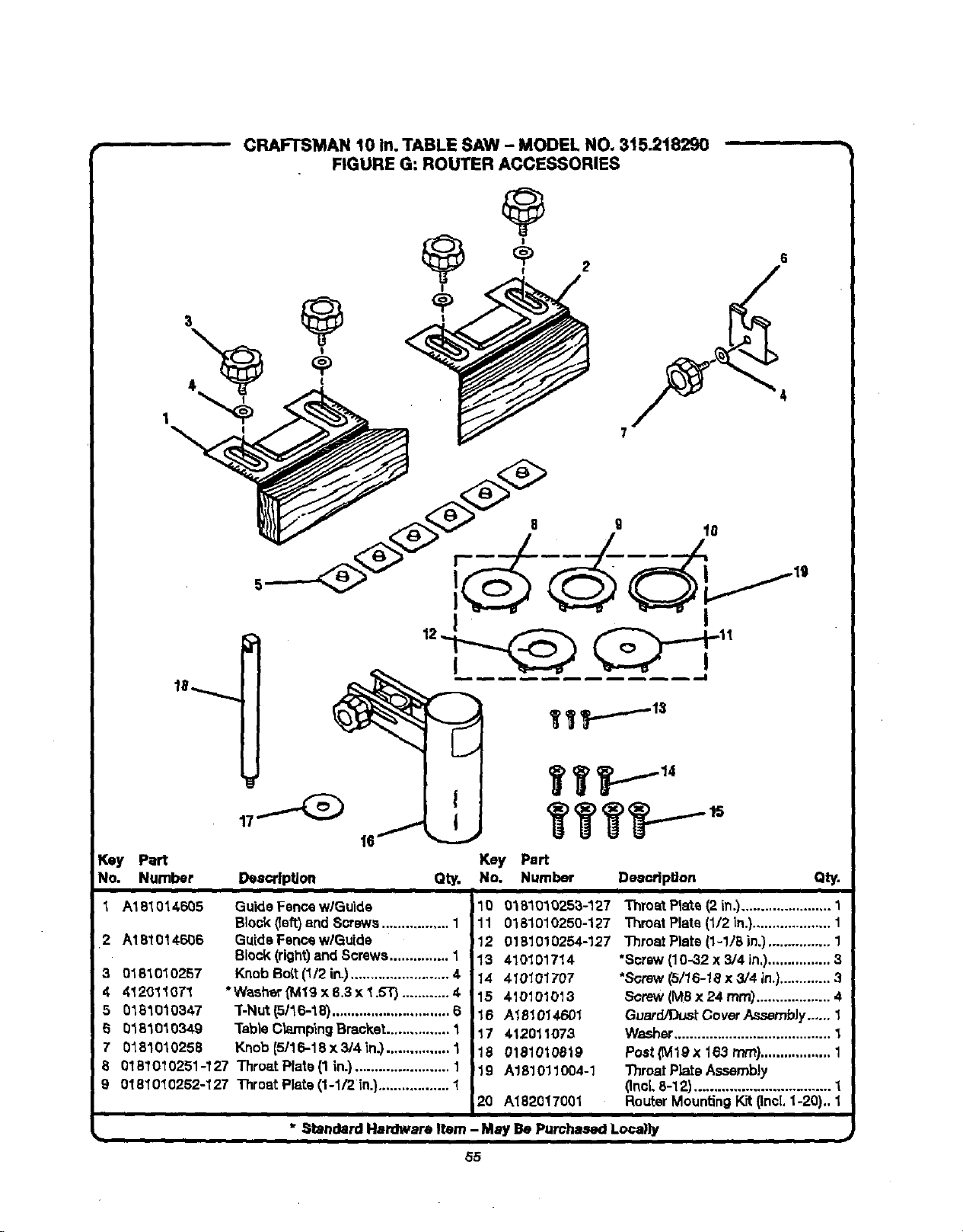
CRAFTSMAN 10 in. TABLE SAW - MODEL NO. 315.218290
FIGURE G: ROUTER ACCESSORIES
r_ey Part Key Part
No. Number Description Qty. No. Number DeaoripUon Qty.
1 A181014605 GuideFence w/Guide
Block(left)and Screws................. 1
2 A181014606 GuideFence wlGutde
Block(right)and Screws............... 1
Knob Bott (1/2 in.)......................... 4
*Washer(Mlg x 8.3x 1.5T) ............ 4
"[-Nut(5/16-18) .............................. 6
"l'ableClampingBracket................ 1
Knob {5/16-18 x 3/4 _n.)................ 1
8 0161010251-127 Throat Plate(1 in.)........................ 1
9 0161010252-127 Throat Plate(1-1/2 in.).................. 1
3 0181010257
4 4120110T1
5 0161010347
5 0161010349
7 0161010258
10 018101025a-127
11 0161010250-127
12 0181010254-127
13 410101714
14 410101707
15 410101013
16 A181014601
17 412011073
18 0181010819
'19 A181011004-1
20 A182017001
Throat Plate (2 in.)....................... 1
Throat Plate(1/2 in.).................... 1
Throat Plate (1-1/8 in.)................ 1
•Screw(10-32 x 3/4 in.)................ 3
•Screw(5/16-18 x 3/4 in.)............. 3
Screw(MSx 24 rnm)................... 4
Guerd/Dusf.CoverAssembJ¥...... 1
Washer........................................ 1
Post(M19X 163 ram).................. 1
ThroatPlateAssembly
(Inci,8-12) ................................. 1
RouterMountingKit (IncL1-20).. 1
* Standard Hardware Item - May Be Purchased Loca)ly
b
55
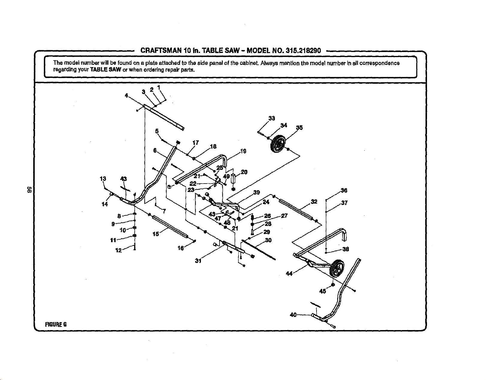
CRAFTSMAN t0 in. TABLE SAW - MODEL NO. 315.218290
I The modelnumberwillbe foundon a plateattached to theside panelofthe cabinet.Always mention themodelnumberinall correspondence J
%
regardingyourTABLESAW orwhen orderingrepairparts.
]
13
14
17
FIGUREG
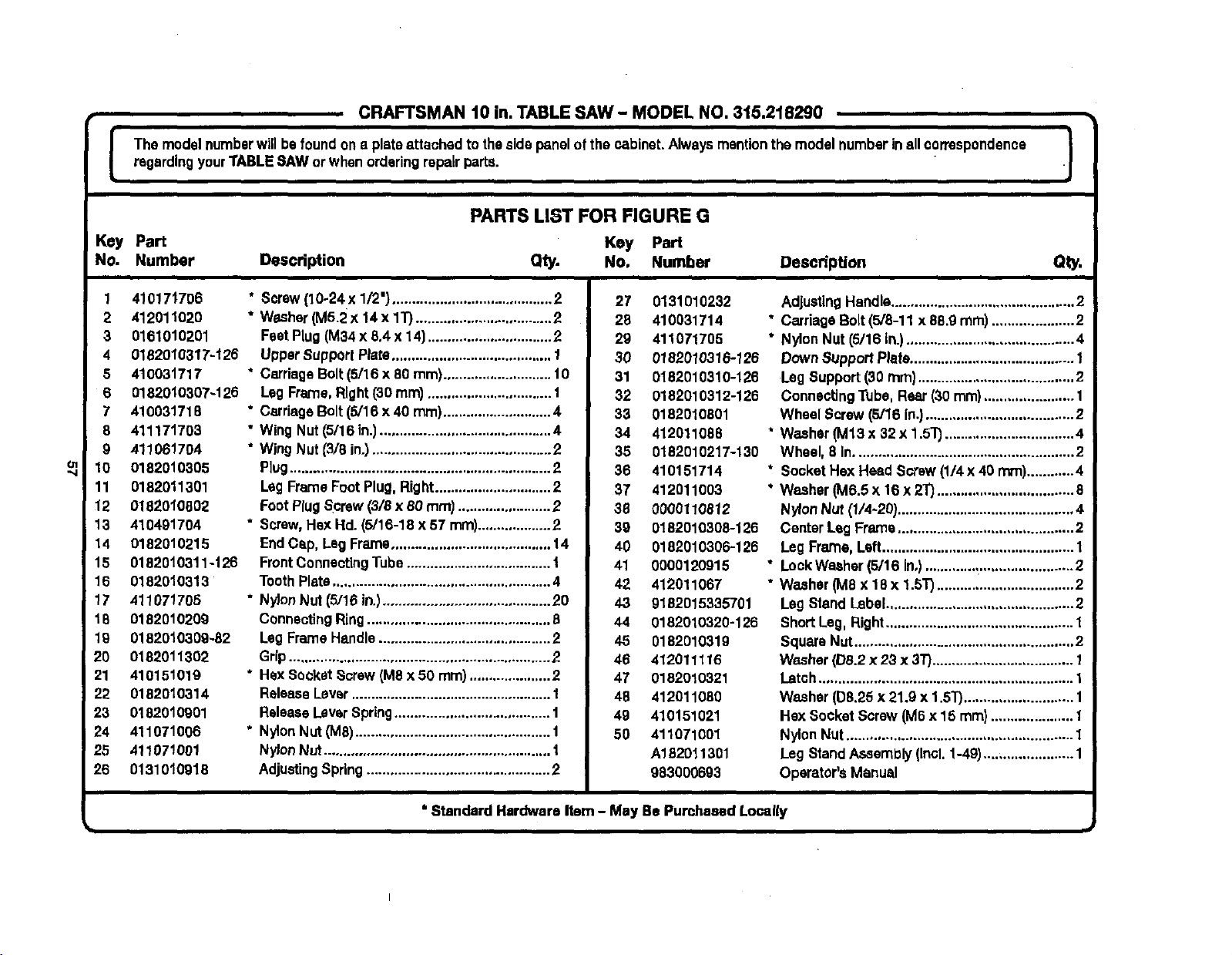
CRAFTSMAN 10 in. TABLE SAW - MODEL NO. 315.218290
l he model numberwillbefound one plateattaohedto thesidepanelofthe cabinet.Alwaysmentionthemodel numberin all correspondence
regardingyourTABLESAW or whenorderingrepairparts.
i
PARTS LIST FOR FIGURE G
Key Part Key Part
NO. Number DescdpUon Qty. No, Number Description
1 4101717O6
2 412011020
3 016101O201
4 0182010317-126
5 410031717
6 0182010307-126
7 410031718
8 411171703
9 411061704
10 0182010305
11 0182011301
12 0182010802
13 410491704
14 0182010215
15 01820t0311-126
16 0182010313
17 411071705
18 0182010209
19 0182010309-32
20 0182011302
21 410151019
22 0182010314
23 0182010901
24 411071006
25 411071001
26 0131010918
• Screw{10-24x 1/2') ......................................... 2
* Washer(M5.2 x 14 x 1T)...................................2
FeetPlug(M34x 8,4 x 14)................................2
UpperSupportPlate......................................... I
* CarriageBolt (5/16 x 80 ram)............................ 10
Leg Frame,Right(30 mm) ................................ I
* CarriageBolt(5/16 x 40 ram)............................4
• Wing Nut (5/16 in.)............................................ 4
• Wing Nut (3/8 in.).............................................. 2
Plug................................................................... 2
LegFrameFoot Plug,Right..............................2
FootPlugScrew(3/8 x 80 ram) ........................2
* Screw,Hax Hd. (5/16-18 x 57 ram)...................2
EndCap, Leg Frame......................................... 14
FrontConnectingTube.....................................t
Tooth Plate........................................................4
• NylonNut (5/16 in.)........................................... 20
ConnectingRing............................................... 8
Leg FrameHandle............................................ 2
Grip................................................................... 2
* Hex SooketScrew(MSx 50 mm).....................2
ReleaseLever................................................... 1
ReleaseLeverSpring........................................ t
* NylonNut (Ms).................................................. t
Nylon NUt.......................................................... t
Adjusting Spring............................................... 2
27 0131010232
28 410031714
29 411071705
30 0182010316-126
31 0182010310-126
32 0182010312-126
33 0182010801
34 412011088
35 0182010217-130
36 410151714
37 412011003
38 0000110812
39 0182010308-126
40 0182010306-126
41 0000120915
42 412011067
43 9182015335701
44 0182010320-126
45 0182010319
46 412011116
47 0182010321
48 412011080
49 410151021
50 411071001
A132011301
983000693
AdjustingHandle............................................... 2
• CarriageBolt(5/8-11 x 88.9turn) ..................... 2
* Nylon Nut (5/16 In.)........................................... 4
Down Support Plate.......................................... 1
Lag Support(30 ram)........................................ 2
ConnectingTube, Rear (30ram)....................... 1
Wheel Screw (5/16 in.)......................................2
* Washer(IV113x 32 x 1.5TJ.................................4
Wheel, 8 in........................................................ 2
* Sooket Hex Head Screw (1/4x 40 rnm)............4
* Washer (M6.5 x 16 x 21) ................................... 8
NylonNut (1/4_20)............................................. 4
CenterLeg Frame............................................. 2
Leg Frame, Left................................................. 1
* LookWaahar (5/16 In,).............,........................ 2
• Washer (M8 x 18 x 1.51)...................................2
Leg Stand Label................................................ 2
ShortLeg, Right................................................ 1
SquareNut........................................................ 2
Washer(D8.2 x 23 x 31").................................... 1
Latch................................................................. 1
Washer (138.26x 21.9 x 1.5T)............................ 1
Hax SocketScrew (M6x 15 ram)..................... 1
NylonNut .......................................................... 1
Leg StandAssembly(Inol.1-49)....................... 1
Operator'sManual
* Standard Hardware Item - May Be Purchased LoP.ally

Your Home
For repair-in your home-of all major brand appliances,
lawn and garden equipment, or heating and cooling systems,
no matter who made it, no matter who sold it]
For the replacement parts, accessories and
owners manuals that you need to do-it-yourself.
For Sears professional installation of home appliances
and items like garage door openers and water heaters.
1-800-4-MY-HOME e (l-s0o-4ss-4_s3)
Call anytime, day or night(U.S.A. and Canada)
www._ar_¢oM www.sears.¢a
i ill i. i,i
Our Home
For repair of carry-in items likevacuums, lawnequipment,
and electronics, call or go on-line forthe locationof your nearest
Sears Parts & Repair Center.
1-800488-1222
Call anytime, day or night (U.S.A. only)
To purchase a protectionagreement (U.S.A.)
or maintenance agreement (Canada) on a productserviced by Sears:
1-800-827-8655 (U.S.A.) 1-800-361-8665 (Canada)
Pare pedir servicto de repamcibn
a domidlio, y pare ordenar piezas:
1-888-SU-HOGAR s"
(1-888-784-6427)
Au Canada pour service en fmnr_rais:
1-800-LE-FOYER _
www.sears.ca
Sears
O I_ "l_rademarkI _ _ I =4Set_k_ Markof Sere, Roebuckand Co.
® Mllrca Re_mlradaI _ Marca deF_brk_ / _ Marcade _wMdo =It 5clips, _ _ _.
_ Mmrquode€ommn_ I m Malqu_d0pos4_ dsStoPs,Rmlbud(alndCo. € Sur=, Roelmud(snd Co.