Loading ...
Loading ...
Loading ...
Installingthedryer.
Exhaust Ducthlg Length
The exhaust _)swm should be inspecwd and cleaned
at least uric( a year with normal usage. The morc the
(hT(.r is u_(/, tile mow oli(.11 ?'l)[i should ch(ck tile
exhaust svsmm and v(nt hood fbr proper operation.
If roof vents or louvcred l)lelmms arc used, th_" nmst
be equivak nt m a 4" dampercd wall cap in rcgaM to
resistance to airflows; prexcnlion of back drali_ and
lllaillt(llall(( rOqllilcd to pl'_ \'_qlt clogging.
• DONOTass_mble the duct work with ti_st(n_rs thai
(xt( lid into th_ duct. Tbey will sel_'_ as colleclion
poims tor lint.
• Ducp, w)rk wbich lalns througll an unheated ar(a or
iS ll¢aF _lll air (onditioning duct sbould I)_ insulaled
t,o r_.duce coud( llSati,.m and lint buildup.
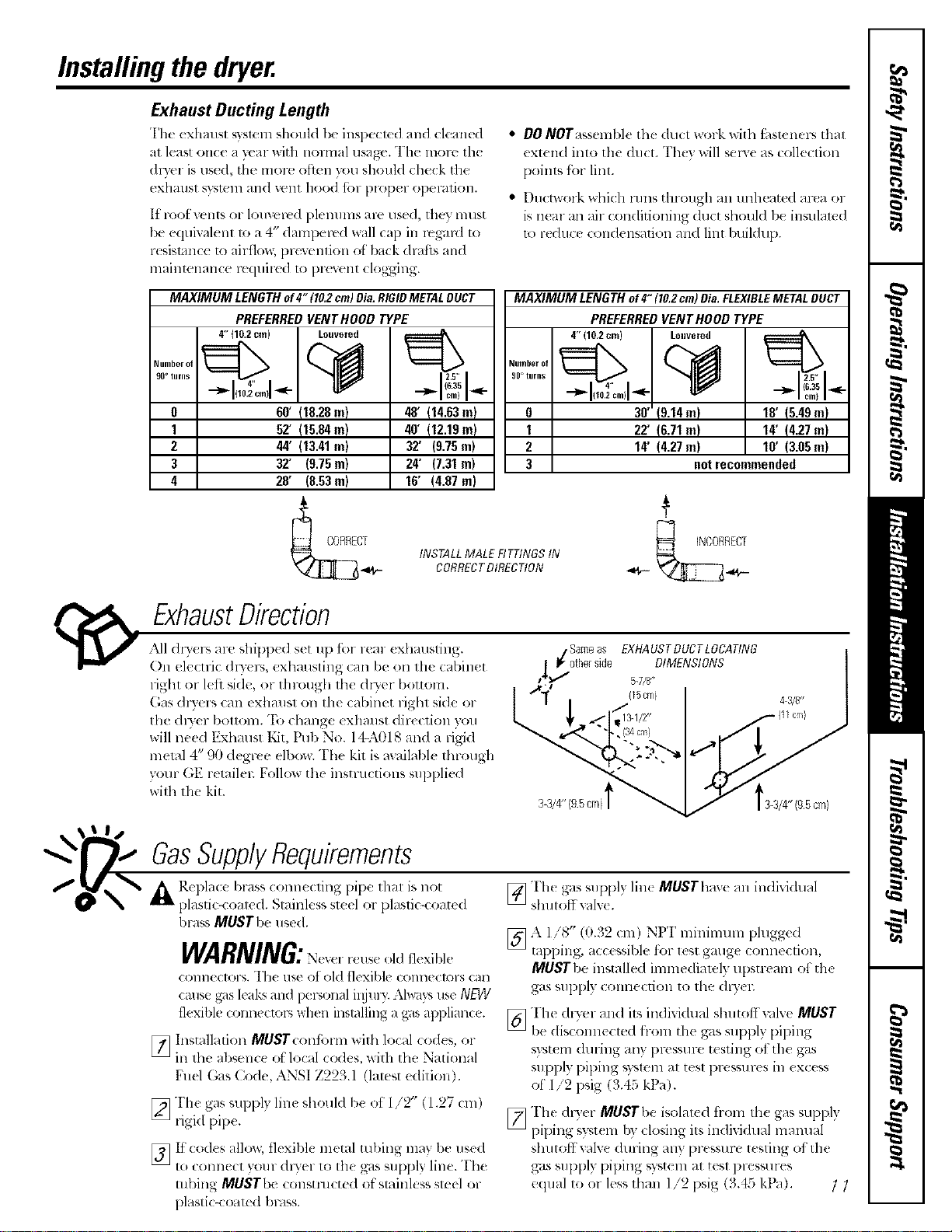
MAXIMUM LENGTHof4"(10,2cm)Oia,RIGIDMETALDUCT
PREFERREDVENTHOOD TYPE
Number of
90otrims
0
1
2
3
4
4" (10.2 cm) Louvered
60' f18.28m)
52' {15.84m)
44' 113.41m)
32" (9.75m)
28' (8.53m)
48' 114.63m)
40' I12.19m)
32' (9.75m)
24' (7.31m)
16' (4.87 m)
MAXIMUM LENGTH of4" (10,2cm) Dia,FLEXIBLEMETALDUCT
NUlnbsr of
90° tllrllS
0
I
2
3
INSTALLMALE RTTINGSIN
CORRECTDIRECTtON
PREFERREDVENTHOODTYPE
4" (10,2era) Louvered
v:>q
aft' 19.14m)
22' 16.71m)
14' (4.27m)
18' 15.48m)
14' 14.27m)
lO' (3.05m)
notrecommended
ExhaustDirection
All dl_ers are shipl)(d set up tbr rear exhausting.
On elt'ctric dly(p,, exhausting can be on tim cabinet
rigbt or left side, or througl_ tbe dl3er bottom.
(;as d13ers can exhmlst on the cabinet figbt side or
the dl)'( r bottom. "It) cbange exllmlst direction you
will need F.xhaust Kit, Pul) No. 14-Afll8 and a rigid
metal 4" 90 degree elbow. "File kit is available tbrough
your GF retailel: Follow the instructions supplied
with tile kit.
L
Sameas EXNAUSTDUCTLOCATING
| P/otherside DIMENSIONS
t4_" 5-7/8"
(_5cm)
• (34cm)
4 3/U
s-3/4"lgsomit 'ts-s/4"igsoml
GasSupplyRequirements
A Replace brasscorm(cling pipe lllal is llot
plastic-coaled. Slainless sl(el or plaslic-coated
I>rassMUSTI>( used.
[]
WARNING: .ldfl¢xibk
comlecu)rs. I'h( use of old flexible colmectors can
cruise g',_sleaks and personal ii!jul?: AhqlT,_use NEW
flexible connectors when installing a gas applimlce.
Installalion MUSTcontorm wilb local co&s. or
ill 1be al)senc( of local (odes, x_ith the National
Fuel Gas Code, ANSI Z223.1 (latest edition).
[_ "I'h( gas supply line should be ot 1/2" (1.27 ('m)
ligid pip(.
[_It" cod(s allow, tl( xibl( m(tal robing may be used
to COIIII{ CI yollr dQ'( 1 1o the gas supply line. "I'h(
tubing MUSTbe COllSttalct{ d of'stainless slc_l or
plastic-coal( d Imlss.
[_The gas supply lin_ MUSTbav( _]11individual
slmtoffxalx(.
[7_ A 1/8 (t).a2 (m) NI 1 llllllll]]!llll plugg(d
rapping, acc(ssible for lesl gaug_ conneclion,
MUSTI.,e installed inmledialely upstream of the
gas supply COllllection tO lbe (h3'el;
[_Th( dlTer and ils individual shutoffvalve MUST
be dis(om_((led from the gas supply piping
syst{ m during any pr(ssure tcsling ot tll( gas
supply piping system al tcsl pressm-es in ex(css
of 1//2 1)sig (3.45 kPa).
[_The dlTer MUSTbe isolal(d from Ibe gas SUl>ply
piping sysl(n_ by closing ils in(li_idual inantlal
slmtoff xalxe (luring any pressm-e testing of th(
gas supply piping system al tesl pressures
/9 • ¢ _, )
e(lualloorlesslb_lli_ ;,sg(3.4_kt ). //
Loading ...
Loading ...
Loading ...